12511HB-11RR-K中文资料
- 格式:pdf
- 大小:576.49 KB
- 文档页数:1
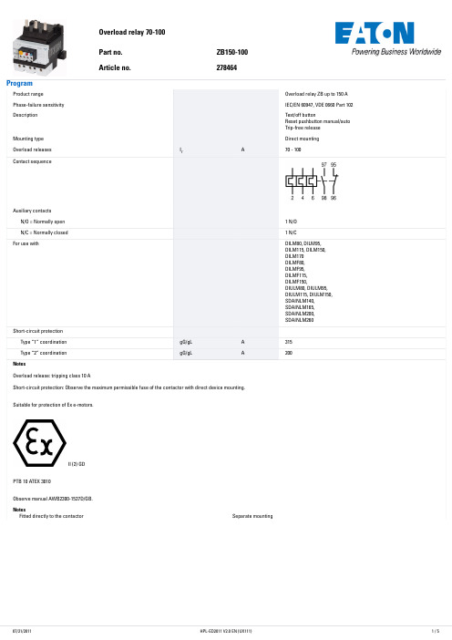

T 04:43:35+02:00型号NI4-DSU26-2Y1X2-H1140货号1051007额定工作距离Sn 4 mm 安装方式非齐平修正系数37#钢 = 1; 铝 = 0.3; 不锈钢= 0.7; 黄铜 = 0.4重复精度ð 2 满量程的 %温度漂移10 %磁滞1…10 %环境温度-25…+70 °C 输出性能4线, NAMUR 阀控制Exi (max. 45 V)开关频率0.05 kHz电压Nom. 8.2 VDC 无激励电流损耗ï 2.1 mA 激励电流损耗ð 1.2 mA认证依据KEMA 02 ATEX 1090X 内置 电感(L ) / 电容 (C )150 nF / 150 µH防爆标志防爆标识为II 2 G/Ex ia IIC T6 Gb /II 1 D Ex ia D 20T95 °C Da(最大 U = 20 V, I = 60 mA, P = 200 mW)警告防静电设计用于阀位回讯检测的双检测面电感式传感器, DSU26尺寸68 x 60 x 35.4 mm外壳材料塑料, 塑料, PA12-GF20, 黄感应面材料塑料, 塑料, PA12-GF20, 黑连接接插件, M12 x 1防震动性55 Hz (1 mm)防冲击性30 g (11 ms)防护等级IP67MTTF 6198 years 符合SN 29500 (Ed.99) 40 °C认证开关状态指示2路LED指示灯 黄/红sATEX 防爆认证II 组设备,设备等级2G. 可用于气体危险1区sATEX 防爆认证,II组设备,可应用于粉尘危险0区s 满足SIL2和IEC61508标准s 长方形,外壳类型DSU26s 塑料, PP -GF30-V0s 检测旋转执行器位置两路输出s 在标准执行器上安装s 2线直流, nom. 8.2 VDCs输出遵循本安型DIN EN 60947-5-6标准(NAMUR)sM12 x 1接插件接线图功能原理电感式传感器以无磨损和非接触的方式来检测金属物体 阀位回讯是专为旋转执行器的位置检测而设计的 它将非接触式电感传感器的可靠性与模块化的外壳系统的灵活性结合起来。
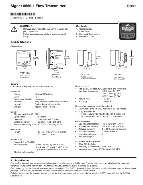
WARNING!• Remove power to unit before wiring input and out-put connections.• Follow instructions carefully to avoid personalinjury.Signet 8550-1 Flow TransmitterContents1. Specifications2. Installation3. E lectrical Connections4. Menu FunctionsCurrent output:• 4 to 20 mA, isolated, fully adjustable and reversible• Max loop impedance: 50 Ω max. @ 12 V325Ω max. @ 18 V600Ω max. @ 24V• Update rate: 100 ms• Accuracy: ±0.03 mAOpen-collector output, optically isolated:• 50 mA max. sink, 30 VDC maximum pull-up voltage.• Programmable for:• High or Low setpoint with adjustable hysteresis• Pulse operation (max rate: 300 pulses/min).Environmental• Operating temperature: -10 to 70°C (14 to 158°F)• Storage temperature: -15 to 80°C (5 to 176°F)• Relative humidity: 0 to 95%, non-condensing• Maximum altitude: 2000 m (6562 ft)• Insulation category: II• Pollution degree: 2Standards and Approvals• CSA, C E, UL listed• Immunity &E missions: E N61326• Manufactured under ISO 9001 and ISO 14001GeneralCompatibility: Signet Flow Sensors (w/freq out)Enclosure:• Rating: N E MA 4X/IP65 front• Case: PBT• Panel case gasket: Neoprene• Window: Polyurethane coated polycarbonate• Keypad: Sealed 4-key silicone rubber• Weight: Approx. 325g (12 oz.)Display:• Alphanumeric 2 x 16 LCD• Update rate: 1 second• Contrast: User selected, 5 levels• Display accuracy: ±0.5% of reading @ 25ºC• Thermal sensitivity shift: ±0.005% of reading per ºCElectrical• Power: 12 to 24 VDC ±10%, regulated61 mA max currentSensor Input:• Range: 0.5 to 1500 Hz• Sensor power: 2-wire: 1.5 mA @ 5 VDC ± 1%3 or4 wire: 20 mA @5 VDC ± 1%Optically isolated from current loop• Short circuit protected2. InstallationProcessPro transmitters are available in two styles: panel mount and fi eld mount. The panel mount is supplied with the necessary hardware to install the transmitter. This manual includes complete panel mounting instructions.Field mounting requires one of two separate mounting kits. The 3-8051 integral kit joins the sensor and instrument together into a single package. The 3-8050 Universal kit enables the transmitter to be installed virtually anywhere.Detailed instructions for integral mounting or other fi eld installation options are included with the 3-8051 Integral kit or the 3-8050 Universal kit.SIDE VIEWField Mount w/8051 Integral kitSIDE VIEWField Mount w/8050 Universal basePanel MountSIDE VIEWFRONT VIEWField Mount &Panel Mount1. Specifi cationsDimensions3-8550.090-1 J 4/05 English*3-8550.090-1*English2Signet 8550-1 Flow Transmitter3. Electrical ConnectionsCaution: Failure to fully open terminal jaws before removing wire may permanently damage instrument.Wiring Procedure1. Remove 0.5 - 0.625 in. (13-16 mm) of insulation from wire end.2. Press the orange terminal lever downward with a small screwdriver to open terminal jaws.3. Insert exposed (non-insulated) wire end in terminal hole until it bottoms out.4. Release orange terminal lever to secure wire in place. Gently pull on each wire to ensure a good connection.Wiring Removal Procedure1. Press the orange terminal lever downward with a small screwdriver to open terminal jaws.2. When fully open, remove wire from terminal.Installation2. Place gasket on instrument, and install in panel.3. Slide mounting bracket over back of instrument until quick-clips snap into latches onside of instrument.4. To remove, secure instrument temporarily with tape from front or grip from rear ofinstrument. DO NOT RELEASE.Press quick-clips outward and remove.3Signet 8550-1 Flow TransmitterStand-alone application, no current loop usedTransmitterAUXILIARY power is used only if the flow sensor requires more than 1.5 mA current.For Signet sensors this is limited to the following products: 2000, 2507, 2551, open collector input signals3.1 System Power/Loop Connections3.2 Sensor Input ConnectionsWiring Tips:• Do not route sensor cable in conduit containing AC power wiring.Electrical noise may interfere with sensor signal.• Routing sensor cable in grounded metal conduit will help preventelectrical noise and mechanical damage.• Seal cable entry points to prevent moisture damage.• Only one wire should be inserted into a terminal. Splice double wiresoutside the terminal.Maximum cable length is 200 ft. for 515/8510-XX, 525 , 2517 and any sinusoidal fl ow signal.Maximum cable length is 1000 ft. for2536/8512-XX, 2540, vortex, and any open collector fl ow signal.No Aux Power515/3-8510-XX 525210025172536/3-8512-XX 25407000 VortexAux Power200025072551Open Coll. InputTerminalsSensr Gnd (SHIELD)Sensr IN (RED)Sensr V+(BLACK)9874Signet 8550-1 Flow TransmitterMonitor the Permanent Totalizer value.Monitor the 4-20 mA Loop output.Monitor date for scheduled maintenance or date of last calibration. (See description in Calibrate Menu.)HysteresisLow SetpointOutput energized Output relaxedHigh SetpointVIEW menu• During normal operation, the ProcessPro displays the VIEW menu.• When using the CALIBRATE or OPTIONS menus, the ProcessPro will return to the VIEW menu if no activityoccurs for 10 minutes.• To select the item you want displayed, press the UP or DOWN arrow keys. The items will scroll in acontinuous loop. Changing the display selection does not interrupt system operations.• No key code is necessary to change display selection.• Output settings cannot be edited from the VIEW menu.3.3 Open Collector OutputThe Open collector output can be used as a switch that responds when the fl ow rate moves above or below a setpoint, or it can be used to generate a pulse that is relative to the fl ow volume or to the fl ow rate.• LowOutput triggers when the fl ow rate is less than the setpoint.The output will relax when the fl ow rate moves above the setpoint plus the hysteresis value.• HighOutput triggers when the fl ow rate is greater than the setpoint.The output will relax when the fl ow rate drops below the setpoint plus the hysteresis value.• FrequencyOutput is a pulse stream that is based on the input fl ow sensor signal. Set for 1 (input frequency = output frequency). Set for even numbers (2, 4, 6, 8 . . . . 254 maximum) to scale output frequency.• PulseOutput is a pulse based on the volume of fl uid that passes the sensor. Set any value from 0.0001 to 99999.The output may be disabled (Off) if not used.View MenuDisplayDescription0.0 GPMTotal: 12345678 >Monitor the fl ow rate and the resettable totalizer. Press the RIGHT ARROW key to reset the totalizer. If the Reset is locked, you will need to enter the Key Code fi rst. Lock or Unlock the totalizer in the OPTIONS menu. This is the permanent View display.All of the displays below are temporary. After ten minutes the display will return to the permanent display.Perm: 12345678GallonsLoop Output:12.00 mALast CAL:04-20-065Signet 8550-1 Flow Transmitter Notes on Steps 5 and 6:• All output functions remain active during editing.• Only the fl ashing element can be edited.• RIGHT ARROW key advances the fl ashing element in a continuous loop.• Edited value is effective immediately after pressing ENTER key.• If no key is pressed for 10 minutes unit will restore the last saved value and return to step 3.• Step 6 (pressing ENTER key) always returns you to Step 3.• Repeat steps 3-6 until all editing is completed.ProcessPro Editing Procedure:Step 1. Press and hold ENTER key:• 2 seconds to select the CALIBRATE menu • 5 seconds to select the OPTIONS menu.Step 2. The Key Code is UP-UP-UP-DOWN keys in sequence.• After entering the Key Code, the display will show the fi rst item in the selected menu.Step 3. Scroll menu with UP or DOWN arrow keys.Step 4. Press RIGHT ARROW key to select menu item to be edited.• The fi rst display element will begin fl ashing.Step 5. Press UP or DOWN keys to edit the fl ashing element.• RIGHT ARROW key advances the fl ashing element.6 Signet 8550-1 Flow TransmitterThe first three characters set the Flow Rate units of measure. They have no effect on calculations. They may be any alpha or numeric character, upper or lower case.The last character sets the Flow rate Timebase. Select S (seconds), M (minutes), H (hours) or D (days).This setting tells the transmitter how to convert the input frequency from the flow sensor into a fl ow rate. The K-factor is unique to the sensor model and to the pipe size and schedule. Refer to data in the sensor manual for the correct value. Limits: 0.0001 to 99999. (The K-factor cannot be set to 0)This setting identifi es the Totalizer units. It has no effect on any calculation. It serves as a label only. Each character can be any alpha or numeric selection, upper or lower case.This setting tells the transmitter how to convert the input frequency from the flow sensor into a volumetric total. It also is used as the basis for the Open Collector pulse mode.The setting is usually the same as the Flow K-factor, or different by x10 or x100. Limits: 0.0001 to 99999. (The K-factor cannot be set to 0)Select the minimum and maximum values for the 4-20 mA Current loop output. The 8550 will allow any values from 0.0000 to 99999.Select the desired mode of operation for the Open Collector output. Options available are High, Low, volumetric Pulse, or Frequency. The signal may be disabled (Off) if not used.In Low or High Mode, the Open Collector output will be activated when the Flow rate reaches this value. Be sure to modify this setting if you change the Flow Units.The Open Collector output will be deactivated at Setpoint ± Hysteresis, depending on High or Low Setpoint selection. (See details on page 4.)In Pulse mode, the Open collector output will generate one pulse when this volume of fl ow passes the sensor. The measurement is based on the Total K-factor. The 8550 will allowany value from 0.0001 to 99999.In Pulse mode, this setting defi nes the duration of the Open Collector output pulse. The 8550 allows any value from 0.1 seconds to 999.9 seconds.In Frequency mode, the Open Collector output will simulate the sensor frequency, divided by this setting. Set for 1 (input frequency = output frequency). Set for even numbers(2, 4, 6, 8 . . . 254 maximum) to scale output frequency.Use this “note pad” to record important dates, such as annual recertifi cation or scheduled maintenance.Calibrate MenuDisplay(Factory settings shown)DescriptionFlow Units:GPM >Flow K-Factor:60 >Total Units:Gallons >Total K-Factor 60 >Loop Range: GPM000.00 → 100.00 >Output Mode:Low > Output Setpnt:10.0 GPM >Output Hys:5.0 GPM >Output Volume:100.00 Gallons >Output PlsWdth:0.1 Seconds >Output Freq.:Divide by1 >Last CAL:4-20-06Options Menu10 s2 s20 s30 s40 s50 s60 s70 svery quickly. (Solid blue line)NOTE: The SENSITIVITY function is ineffective if the AVERAGING function is set to zero (seconds).Signet 8550-1 Flow Transmitter7“- - - - -”“Pulse Overrun”“Value must be more than 0”Open Collector is always activatedFlow rate exceeds display capability• Open Collector pulse rate exceeds maximum of 300 pulses per minute.• Pulse width set too wide.K-factors cannot be set to 0.• Hysteresis value too large • Defective transmitter• Increase Flow units time base • Move fl ow decimal one place to the right• Increase Pulse volume setting • Decrease pulse width setting. • Reduce system fl ow rateEnter K-factor from 0.0001 to 99999• Change the hysteresis value• Replace transmitterGeorge Fischer Signet, Inc. 3401 Aerojet Avenue, El Monte, CA 91731-2882 U.S.A. • Tel. (626) 571-2770 • Fax (626) 573-2057For Worldwide Sales and Service, visit our website: • Or call (in the U.S.): (800) 854-40903-8550.090-1 J 4/05 English © George Fischer Signet, Inc. 2002 TroubleshootingDisplay ConditionSuggested SolutionsPossible CausesOrdering InformationMfr. Part No.CodeDescription3-8550-1159 000 047 Flow transmitter, Field mount 3-8550-1P 159 000 048 Flow transmitter, Panel mount3-8550-2 159 000 049 Flow transmitter, Field mount with relays 3-8550-2P 159 000 050 Flow transmitter, Panel mount with relays3-8550-3 159 000 051 Flow transmitter, Field mount with dual input/output 3-8550-3P159 000 052Flow transmitter, Panel mount with dual input/outputAccessoriesMfr. Part No.CodeDescription3-8050 159 000 184 Universal mounting kit 3-8051 159 000 187 Flow Integral Mnt NPT 3-8050.395 159 000 186 Splashproof rear cover 3-8050.396 159 000 617 RC Filter kit (for relay use)3-0000.596 159 000 641 Heavy duty wall mount bracket 3-5000.598 198 840 225 Surface Mount Bracket3-5000.399 198 840 224 5 x 5 inch adapter plate for Signet retrofi t3-9000.392 159 000 368 Liquid tight connector kit for rear cover (includes 3 connectors)3-9000.392-1 159 000 839 Liquid tight connector kit, NPT (1 piece)3-9000.392-2 159 000 841 Liquid tight connector kit, PG13.5 (1 piece)7300-7524 159 000 687 24 VDC Power Supply 7.5 Ω, 300mA 7300-1524 159 000 688 24 VDC Power Supply 15 Ω, 600mA 7300-3024 159 000 689 24 VDC Power Supply 30 Ω, 1.3 A 7300-5024 159 000 690 24 VDC Power Supply 50 Ω, 2.1 A 7300-1024 159 000 69124 VDC Power Supply 100 Ω, 4.2 A。
美瑞克仪器MEIRUIKE INSTRUMENTManua l使用说明书深圳市美瑞克电子科技有限公司版本历史:由于说明书中可能存在错误或遗漏、改进和完善仪器功能、更新技术及升级软件,本说明书将做相应的调整和修订、不断完善以利于使用。
请关注所使用的软件版本及说明书版本。
2020年12月 VER1.02021年07月 VER2.0(地址更新)2021年09月 VER3.0(售后电话变更)2021年12月 VER4.0(修改单位符号K大小写、更正语句错误、添加附件型号)声明:本公司可能对该产品的性能、功能、软件、结构、外观、附件、包装以及说明书等进行完善和提高,如有修改,恕不另行通知!如造成疑惑,请与本公司联系。
目录一、产品概述2二、产品规格...........................................................................................................22.1RK 2511AL 系列简介:.................................................................................22.2测试范围.......................................................................................................22.3测试量程...................................................................................................22.4显示范围...................................................................................................2.5测试速度...................................................................................................2.6触发方式...................................................................................................三、参数规格及相应说明.......................................................................................3.1具体参数...................................................................................................3.2一般技术指标...............................................................................................3.3测试端、基准端说明...................................................................................四、面板、后板介绍...............................................................................................4.1前面板功能介绍...........................................................................................4.2后面板功能介绍............................................................................................五、操作说明.......................................................................................................5.1上电启动...................................................................................................5.2开始测试.....................................................................................................5.3选择测试速度.............................................................................................5.4选择测试量程.............................................................................................5.5清零标准.....................................................................................................5.6功能菜单.....................................................................................................5.7后面板HANDLER 接口介绍(选配)........................................................5.8串行RS-232标准接口(选配)..............................................................六、串口通讯指令(仅适用于RK2511ALR )七、常见故障及维护.............................................................................................7.1常见故障排除..............................................................................................7.2更换保险说明.................................................................................................7.3产品保修说明............................................................................................................................................................................................................334566788888991113152020207.4装箱清单. (21)203336.1指令格式简要说明..............................................................................................6.2基本指令..............................................................................................附录:选型表.............................................................................................151591........................................................一、产品概述RK2511AL/BL 系列是一款经济实用的直流电阻测试仪,具有更广的测试范围:0.01m Ω~200.0KΩ,最大显示数5000数。

目录第一章 SDH原理 (2)第二章马可尼SDH光端机 (5)第一节SMA16-64产品简介 (5)第二节单元描述 (6)第三节单元卡介绍 (10)第四节功能概述 (13)第三章设备预防性试验 (14)第一节设备预防性试验项目 (14)第四章设备日常巡视项目 (19)第五章设备运行维护注意事项 (22)第一章 SDH原理一、SDH定义:同步数字序列SDH(Synchronous Digital Hierarchy),是有关通过物理传输网络,传送适配的的净负荷标准化数字传输结构的一个系列集。
二、SDH等级速率:ITU-TG.707中规定了SDH的各等级速率。
其中最基本的模块是STM-1,速率为155。
52Mbit/s,更高等级的是STM-N,其中N为正整数,即N=1,4,16,64。
三、SDH中STM—N 帧结构SDH帧结构是一种矩形块状结构,由270×N列和9行字节组成,每个字节有8bit。
帧中字节是从左往右,从上往下按行进行传输的,传完一帧再传下一帧,每秒共传8000帧。
每个基本帧的周期为125μs,即帧频为8kHz,每个字节为8bit,则STM-1的速率为: Fb=8000×270×9×8=155520000bit/s=155。
52M bit/s由下图可以看出,SDH帧结构大体可以分为三个区域(1)段开销区域:为保证信息净负荷正常灵活传输所必需的附加字。
(2)管理单元指针:用来指示信息净负荷的第一个字节在STM-N帧内准确的位置,以便在接收端正确分解的指示符。
(3)信息净负荷区域:帧结构中存放信息的区域.三、四、SDH复用基本概念:(1)映射:将各支路适配进相应的VC中称为映射。
(2)复接:将多个低阶通道层信号适配到高阶通道,或将多个高阶通道信号适配进复接段的称为复接。
(3)定位:将VC放进支路单元或管理单元,同时将其与帧参考点的偏差也作为信息结合进去的过程为定位。
各种电阻的特性
碳膜电阻器(RT)
材料:高温下将有机化合物(烷,苯等碳氢化合物)热分解产生的碳积在陶瓷肌体表面。
碳膜电阻器阻值范围宽,由良好的稳定性,温度系数不大且是负值,是目前应用最广泛的电阻器。
超小型碳膜电阻:RT13 功率:0.125W 阻值范围:1-1M 允差:G,J,K环境温度范围:-55---125C 额定温度70 C 最大工作电压:150V温度系数:
-400---1500PPM 最大重量:0.1G
碳膜电阻:RT-0.25 功率:0.25W 阻值范围:10-5.1M 允差:J,K环境温度范围:-55---100C 额定温度40 C 最大工作电350V 温度系数:
-600---1200PPM 最大重量:1.5G
碳膜电阻:RT-1 功率:1W 阻值范围:27-10M 允差:J,K
环境温度范围:-55---100C 额定温度40 C 最大工作电压:700V温度系数:-600---1200PPM 最大重量:3.4G
金属膜电阻(RJ)
材料:通过真空蒸发或阴极溅射,沉积在陶瓷肌体表面上一层很薄的金属或合金膜。
特点:金属膜电阻比碳膜电阻的精度高,稳定性好,噪声,温度系数小,金属膜电阻由于结构不均匀,因此使他的脉冲负载能力差。
RJ13 功率:0.125W 阻值范围:100-510K 允差:,J,K
最大工作电压:150V 温度系数:+-500PPM 最大重量:0.1G。

LOC111中⽂资料LOC111Linear OptocouplersApplicationsFeaturesDescriptionApprovalsOrdering Information Pin ConfigurationLOC111 is a linear optocoupler for use in telecom, med-ical and power supply isolation circuits. They are available in 8 pin DIP , surface mount or flatpack packages.Modem Transformer Replacement With No Insertion LossDigital Telephone IsolationPower Supply Feedback Voltage/Current Medical Sensor Isolation Audio Signal InterfacingIsolation of Process Control TransducersUL Recognized: File Number E76270CSA Certified: File Number LR 43639-10BSI Certified:BS EN 60950:1992 (BS7002:1992)Certificate #:7344 BS EN 41003:1993Certificate #:73448 Pin Flatpack or DIP PAckage (PCMCIA Compatible)?Couples Analog and Digital Signals ?Wide Bandwidth (>200kHz)?High Gain StabilityLow Input/Output Capacitance Low Power Consumption 0.01% Servo Linearity THD 87dB TypicalMachine Insertable, Wave SolderableSurface Mount and Tape Reel Versions Available VDE CompatibleLOC111 PinoutDLED +LED +V cc 1I1NC NC +V cc 2I 2LOC111Absolute Maximum Ratings are stress ratings. Functional operation of the device at these or any other conditions beyond those indicated in the operational sections of this data sheet is not implied. Exposure of the device to the absolute maximum ratings for an extended period may degrade the device and effect its reliability.Absolute Maximum Ratings (@ 25o C)Electrical Characteristics2Derate Linearly 6.67 mW/°CK3 Sorted Bins Bin A= 0.550-0.605Bin B = 0.606-0.667Bin C = 0.668-0.732Bin D = 0.733-0.805Bin E = 0.806-0.886Bin F = 0.887-0.974Bin G = 0.975-1.072Bin H = 1.073-1.179Bin I = 1.180-1.297Bin J= 1.298-1.426The LOC110/LOC111/LOC112 are shipped in anti-static tubes of 50pieces. Each tube will contain one K3 sorted bin.Bin designation marked on each device (A-J).Orders for the LOC110 product will be shipped using bins available at the date of the order. Any bin (A-J) can be shipped.For customers requiring selected bins D E F G we offer part num-bers LOC111 or LOC112.LOC111Performance Data*The Performance data shown in the graphs above is typical of device performance. For guaranteed parameters not indicated in the written specifications, please contact our application department.LOC111Dimensionsmm (inches)Mechanical DimensionsCPC7581 Mechanical DimensionsDimensionsmm(inches)CLARE LOCATIONSClare Headquarters78 Cherry Hill DriveBeverly, MA01915Tel: 1-978-524-6700Fax: 1-978-524-4900Toll Free: 1-800-27-CLARE Clare Micronix Division 145 ColumbiaAliso Viejo, CA92656-1490 Tel: 1-949-831-4622Fax: 1-949-831-4628SALES OFFICES AMERICASAmericas HeadquartersClare78 Cherry Hill DriveBeverly, MA01915Tel: 1-978-524-6700Fax: 1-978-524-4900Toll Free: 1-800-27-CLARE Eastern RegionClareP.O. Box 856Mahwah, NJ 07430Tel: 1-201-236-0101Fax: 1-201-236-8685Toll Free: 1-800-27-CLARE Central RegionClare Canada Ltd.3425 Harvester Road, Suite 202 Burlington, Ontario L7N 3N1 Tel: 1-905-333-9066 Fax: 1-905-333-1824Western RegionClare1852 West 11th Street, #348 Tracy, CA95376Tel: 1-209-832-4367Fax: 1-209-832-4732Toll Free: 1-800-27-CLARE CanadaClare Canada Ltd.3425 Harvester Road, Suite 202 Burlington, Ontario L7N 3N1 Tel: 1-905-333-9066 Fax: 1-905-333-1824EUROPEEuropean HeadquartersCP Clare nvBampslaan 17B-3500 Hasselt (Belgium)Tel: 32-11-300868Fax: 32-11-300890FranceClare France SalesLead Rep99 route de Versailles 91160 ChamplanFranceTel: 33 1 69 79 93 50Fax: 33 1 69 79 93 59 GermanyClare Germany Sales ActiveComp Electronic GmbH Mitterstrasse 1285077 ManchingGermanyTel: 49 8459 3214 10Fax: 49 8459 3214 29ItalyC.L.A.R.E.s.a.s.Via C. Colombo 10/AI-20066 Melzo (Milano) Tel: 39-02-95737160Fax: 39-02-95738829 SwedenClare SalesComptronic ABBox 167S-16329 Sp?ngaTel: 46-862-10370Fax: 46-862-10371United KingdomClare UK SalesMarco Polo HouseCook WayBindon RoadTauntonUK-Somerset TA2 6BG Tel: 44-1-823 352541Fax: 44-1-823 352797ASIA PACIFICAsian HeadquartersClareRoom N1016, Chia-Hsin, Bldg II,10F, No. 96, Sec. 2Chung Shan North RoadTaipei, Taiwan R.O.C.Tel: 886-2-2523-6368Fax: 886-2-2523-6369/doc/0fd841f2770bf78a64295400.html Worldwide Sales OfficesSpecification: DS-LOC111-R6Copyright 2001, Clare, Inc.All rights reserved. Printed in USA.02/23/01Clare cannot assume responsibility for use of any circuitry other than circuitry entirely embodied in this Clare product. No circuit patent licenses nor indemnity are expressed or implied. Clare reserves the right to change the specification and circuitry, with-out notice at any time. The products described in this document are not intended for use in medical implantation or other direct life support applications where malfunction may result in direct phys-ical harm, injury or death to a person.。
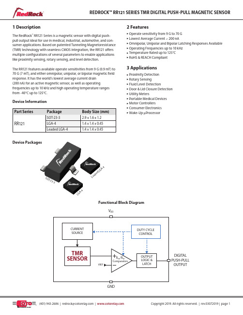
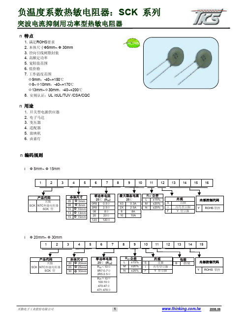
1 DescriptionThe RedRock ™ RR121 Series is a magnetic sensor with digital push-pull output ideal for use in medical, industrial, automotive, and con-sumer applications. Based on patented Tunneling Magnetoresistance (TMR) technology with seamless CMOS integration, the RR121 offers multiple configurations of several parameters to enable applications like proximity sensing, rotary sensing, and level detection.The RR121 features available operate sensitivities from 9 G (0.9 mT) to 70 G (7 mT), and either omnipolar, unipolar, or bipolar magnetic field response. It has the world’s lowest average current drain (200 nA) for an active magnetic sensor, as well as operatingfrequencies up to 10 kHz and high operating temperature ranges from -40°C up to 125°C.2 FeaturesuOperate sensitivity from 9 G to 70 G u Lowest Average Current < 200 nAu Omnipolar, Unipolar and Bipolar Latching Responses Available u Operating Frequencies up to 10 kHz u Temperature Rated up to 125°C u RoHS & REACH Compliant3 ApplicationsuProximity Detection u Rotary Sensingu Fluid Level Detectionu Door & Lid Closure Detection u Utility Metersu Portable Medical Devices u Motor Controllers u Consumer Electronics u Wake-Up m ProcessorFunctional Block DiagramV DDDIGITAL PUSH-PULL OUTPUTGNDS OT -23-3L GA-4L ea ded L G A -4Device PackagesDevice InformationTable of Contents1. Description (1)2. Features (1)3. Applications (1)4. Specifications for all RR121 Series Sensors (4)4.1 Absolute Environmental Ratings for all RR121 Series Sensors (4)4.2 Absolute Electrical Ratings for all RR121 Series Sensors (4)4.3 Operating Electrical Characteristics for all RR121 Series Sensors (4)5. Operating Characteristics for RR121-1B13-311 and RR121-1B13-312 (5)6. Operating Characteristics for RR121-1A23-311 (5)7. Operating Characteristics for RR121-1F23-31 (6)8. Operating Characteristics for RR121-1B53-311 (6)9. Operating Characteristics for RR121-1A53-311 (7)10. Operating Characteristics for RR121-1E73-311 (7)11. Operating Characteristics for RR121-1B93-312 (7)12. Operating Characteristics for RR121-2A32-364 (8)13. Operating Characteristics for RR121-3C63-311 (8)14. Operating Characteristics for RR121-3C73-311 (8)15. Operate & Release Lobe Plots (9)15.1 RR121-1B13-311 (9)15.2 RR121-1B13-312 (9) (9)15.3 RR121-1A23-31115.4 RR121-1B53-311 (9)16. Graphs - Typical Electrical Characteristics (10)16.1 RR121-1B13-311 & RR121-1B13-312 Average Supply Current vs Supply Voltage vs Temperature (10)16.2 RR121-1B13-311 & RR121-1B13-312 Average Supply Current vs Temperature vs Supply Voltage (10)16.3 RR121-1B13-311 & RR121-1B13-312 Sampling Frequency vs Supply Voltage vs Temperature (10)16.4 RR121-1B13-311 & RR121-1B13-312 B OPN (Blue) and B OPS (Red) vs Supply Voltage at +25ºC (11)16.5 RR121-1B13-311 & RR121-1B13-312 B RPN (Blue) and B RPS (Red) vs Supply Voltage at +25ºC (11)16.6 RR121-1B13-311 & RR121-1B13-312 B OPN (Blue) and B OPS (Red) vs Operating Temperature at V DD=3.0 V (11)16.7 RR121-1B13-311 & RR121-1B13-312 B RPN (Blue) and B RPS (Red) vs Operating Temperature at V DD=3.0 V (11)16.8 RR121-1A23-311 & RR121-1F23-311 & RR121-2E23-311 Average Supply Current vs Supply Voltage vs Temperature (12)16.9 RR121-1A23-311 & RR121-1F23-311 & RR121-2E23-311 Average Supply Current vs Temperature vs Supply Voltage (12)16.10 RR121-1A23-311 & RR121-1F23-311 & RR121-2E23-311 Sampling Frequency vs Supply Voltage vs Temperature (12)16.11 RR121-1A23-311 B OPN (Blue) and B OPS (Red) vs Supply Voltage at +25ºC (13)16.12 RR121-1A23-311 B RPN (Blue) and B RPS (Red) vs Supply Voltage at +25ºC (13)16.13 RR121-1A23-311 B OPN (Blue) and B OPS (Red) vs Operating Temperature at V DD=3.0 V (13)16.14 RR121-1A23-311 B RPN (Blue) and B RPS (Red) vs Operating Temperature at V DD=3.0 V (13)16.15 RR121-1B53-311 & RR121-1A53-311 Average Supply Current vs Supply Voltage vs Temperature (14)16.16 RR121-1B53-311 & RR121-1A53-311 Average Supply Current vs Temperature vs Supply Voltage (14)16.17 RR121-1B53-311 & RR121-1A53-311 Sampling Frequency vs Supply Voltage vs Temperature (14)16.18 RR121-1B53-311 B OPN (Blue) and B OPS (Red) vs Supply Voltage at +25ºC (15)16.19 RR121-1B53-311 B RPN (Blue) and B RPS (Red) vs Supply Voltage at +25ºC (15)16.20 RR121-1B53-311 B OPN (Blue) and B OPS (Red) vs Operating Temperature at V DD=3.0 V (15)16.21 RR121-1B53-311 B RPN (Blue) and B RPS (Red) vs Operating Temperature at V DD=3.0 V (15)16.22 RR121-3C63-311 Average Supply Current vs Supply Voltage vs Temperature (16)16.23 RR121-3C63-311 Average Supply Current vs Temperature vs Supply Voltage (16)16.24 RR121-3C63-311 Sampling Frequency vs Supply Voltage vs Temperature (16)16.25 RR121-1E73-311 & RR121-3C73-311 Average Supply Current vs Supply Voltage vs Temperature (17)16.26 RR121-1E73-311 & RR121-3C73-311 Average Supply Current vs Temperature vs Supply Voltage (17)16.27 RR121-1E73-311 & RR121-3C73-311 Sampling Frequency vs Supply Voltage vs Temperature (17)16.28 RR121-1B93-312 & RR121-3C73-311 Sampling Frequency vs Supply Voltage vs Temperature (17)16.29 RR121-1B93-312 B OPN (Blue) and B OPS (Red) vs Supply Voltage at +25ºC (18)16.30 RR121-1B93-312 B RPN (Blue) and B RPS (Red) vs Supply Voltage at +25ºC (18)16.31 RR121-1B93-312 B OPN (Blue) and B OPS (Red) vs Operating Temperature at V DD=3.0 V (18)16.32 RR121-1B93-312 B RPN (Blue) and B RPS (Red) vs Operating Temperature at V DD=3.0 V (18)16.33 RR121-1B93-312 Average Supply Current vs Supply Voltage vs Temperature (19)16.34 RR121-1B93-312 Average Supply Current vs Temperature vs Supply Voltage (19)17. Application Information (20)17.1 Application Circuit (SOT-23-3) (20)17.2 Application Circuit (LGA-4) (20)17.3 Application Circuit (Leaded LGA-4) (20)18. Part Selection & Ordering Information (21)18.1 Part Selection Table (21)18.2 Device Nomenclature Ordering Information (21)19. Axis of Sensitivity (21)20.Dimensions (22)20.1 LGA-4 Package Dimensions (22)20.2 SOT-23-3 Package Dimensions (22)20.3 Leaded LGA-4 Package Dimensions (22)21. T MR Sensor Location (23)21.1 LGA Package (23)21.2 SOT Package (23)21.3 Leaded LGA Package (23)22. Magnetic Flux Response Diagrams (24)22.1 Omnipolar Magnetic Flux Response (Active Low Option) (24)22.2 Bipolar Magnetic Flux Response (Active Low Option) (24)22.3 Unipolar Magnetic Flux Response (Dual Active Low Option) (24)23. Output Behavior vs. Magnetic Field Diagrams (25)23.1 Output Behavior vs. Magnetic Field - Omnipolar (25)23.2 Output Behavior vs. Magnetic Field - Bipolar (25)23.3 Output Behavior vs. Magnetic Field - Unipolar (Dual Output) (25)24. TMR Sensor & Switch Packaging (26)24.1 SOT-23-3 Tape & Reel Packaging (26)24.2 LGA-4 & Leaded LGA-4 Tape & Reel Packaging (27)25. Suggested Pb-Free Reflow Profile (28)26. Suggested Solder Pad Layout (29)26.1 SOT-23-3 Solder Pad Layout (29)26.2 LGA-4 Solder Pad Layout (29)26.3 Leaded LGA-4 Solder Pad Layout (29)4 Specifications for all RR121 Series Sensors4.1 Absolute Environmental Ratings for all RR121 Series Sensors14.2 Absolute Electrical Ratings for all RR121 Series Sensors14.3 Operating Electrical Characteristics for all RR121 Series Sensors2Notes:1. Exceeding Absolute Ratings may cause permanent damage to the device. Exposure at the maximum rated conditions for extended periods of time mayalso affect device reliability.2. Unless otherwise specified, all characteristics are measured at 25ºC.3. See "Magnetic Field vs. Output Status" for more details.ESD Note: This product uses semiconductors that can be damaged by electrostatic discharge (ESD). When handling, proper ESD precautions should be taken to avoid performance degradation or loss of functionality. Damage due to inappropriate handling is not covered under warranty.5 Operating Characteristics for RR121-1B13-311 and RR121-1B13-3121Notes:1. Unless otherwise specified, V DD =2.7 V to3.6 V, T A = -40ºC to +125ºC. Typical values are V DD = 3.0 V and T A = +25ºC.2. Conditions: t = 10 seconds3. Conditions: B HYST = | B OP -B RP |6 Operating Characteristics for RR121-1A23-3111Notes:1. Unless otherwise specified, V DD =2.7 V to3.6 V, T A = -40ºC to +125ºC. Typical values are V DD = 3.0 V and T A = +25ºC.2. Conditions: t = 10 seconds3. Conditions: B HYST = | B OP -B RP |Notes:1. Unless otherwise specified, V DD =2.7 V to3.6 V, T A = -40ºC to +125ºC. Typical values are V DD = 3.0 V and T A = +25ºC.2. Conditions: t = 10 seconds3. Conditions: B HYST = | B OP -B RP |8 Operating Characteristics for RR121-1B53-3111Notes:1. Unless otherwise specified, V DD =2.7 V to3.6 V, T A = -40ºC to +125ºC. Typical values are V DD = 3.0 V and T A = +25ºC.2. Conditions: t = 10 seconds3. Conditions: B HYST = | B OP -B RP |10 Operating Characteristics for RR121-1E73-311111 Operating Characteristics for RR121-1B93-3121Notes:1. Unless otherwise specified, V DD =2.7 V to3.6 V, T A = -40ºC to +125ºC. Typical values are V DD = 3.0 V and T A = +25ºC.2. Conditions: t = 10 seconds3. Conditions: B HYST = | B OP -B RP |13 Operating Characteristics for RR121-3C63-311114 Operating Characteristics for RR121-3C73-3111Notes:1. Unless otherwise specified, V DD =2.7 V to3.6 V, T A = -40ºC to +125ºC. Typical values are V DD = 3.0 V and T A = +25ºC.2. Conditions: t = 10 seconds3. Conditions: B HYST = | B OP -B RP |15 Operate & Release Lobe PlotsOperate and release distances show are relative. The actual operate and release distances will depend on the type of magnet that is used.15.1 RR121-1B13-31115.2 RR121-1B13-312–––– Operate Distance (mm)–––– Release Distance (mm)–––– Operate Distance (mm)–––– Release Distance (mm)15.3 RR121-1A23-311–––– Operate Distance (mm)–––– Release Distance (mm)15.4 RR121-1B53-311–––– Operate Distance (mm)–––– Release Distance (mm)16 Graphs - Typical Electrical CharacteristicsV DD = 3.0 V and T A = +25 ºC, C DD = 1.0 µF (unless otherwise specified)A v e r a g e S u p p l y C u r r e n t (n A )010*******4005006002.92.72.53.13.33.53.7Supply Voltage (V)S a m p l i n g F r e q u e n c y (H z )1.01.31.61.92.22.52.8A v e r a g e S u p p l y C u r r e n t (n A )010020030040050060020-15-505590125160Ambient Temperature (ºC)16.1 RR121-1B13-311 and RR121-1B13-312Average Supply Current vs.Supply Voltage vs. Temperature16.2 RR121-1B13-311 and RR121-1B13-312Average Supply Current vs.Temperature vs. Supply VoltageS a m p l i n g F r e q u e n c y (H z ) 1.01.31.61.92.22.52.82.92.72.53.13.33.53.7Supply Voltage (V)16.3 RR121-1B13-311 and RR121-1B13-312Sampling Frequency vs.Supply Voltage vs. Temperature16 Graphs - Typical Magnetic CharacteristicsV DD = 3.0 V and T A = +25 ºC, C DD = 1.0 µF (unless otherwise specified)B O P (G )-45-30-1501530452.9-2.7-2.5 3.13.33.53.7Supply Voltage (V)B R P (G )-30-20-10010203010-20-504070100130Operating Temperature (ºC)B R P (G )-30-20-1020302.9-2.7-2.53.1 3.3 3.5 3.7Supply Voltage (V)B O P (G )-45-30-1515304510-20-504070100130Operating Temperature (ºC)B R P (G )-30-20-10010203010-20-504070100130Operating Temperature (ºC)16.4 RR121-1B13-311 and RR121-1B13-312B OPN (Blue) and B OPS (Red) vs. Supply Voltage at +25ºC16.6 RR121-1B13-311 and RR121-1B13-312B OPN (Blue) and B OPS (Red) vs. Operating Temperature at V DD =3.0 V16.5 RR121-1B13-311 and RR121-1B13-312B RPN (Blue) and B RPS (Red) vs. Supply Voltage at +25ºC16.7 RR121-1B13-311 and RR121-1B13-312B RPN (Blue) and B RPS (Red) vs. Operating Temperature at V DD =3.0 V16 Graphs - Typical CharacteristicsV DD = 3.0 V and T A = +25 ºC, C DD = 1.0 µF (unless otherwise specified)A v e r a g e S u p p l y C u r r e n t (n A )0100200300400500600Supply Voltage (V)A v e r a g e S u p p l y C u r r e n t (n A )0100200300400500600Ambient Temperature (ºC)16.8 RR121-1A23-311 and RR121-1F23-311Average Supply Current vs.Supply Voltage vs. Temperature16.9 RR121-1A23-311 and RR121-1F23-311Average Supply Current vs.Temperature vs. Supply VoltageS a m p l i n g F r e q u e n c y (H z )7.08.09.010.011.012.013.02.92.72.53.13.33.53.7Supply Voltage (V)16.10 RR121-1A23-311 and RR121-1F23-311Sampling Frequency vs.Supply Voltage vs. Temperature16 Graphs - Typical Magnetic CharacteristicsV DD = 3.0 V and T A = +25 ºC, C DD = 1.0 µF (unless otherwise specified)B O P (G )-12-8-4048122.9-2.7-2.5 3.13.33.53.7Supply Voltage (V)B O P (G )-15-10-505101510-20-504070100130Operating Temperature (ºC)B R P (G )-7.5-5.0-2.502.55.07.510-20-504070100130Operating Temperature (ºC)B R P (G )-9-6-33692.9-2.7-2.53.1 3.3 3.5 3.7Supply Voltage (V)16.11 RR121-1A23-311 B OPN (Blue) and B OPS (Red) vs. Supply Voltage at +25ºC16.12 RR121-1A23-311 B RPN (Blue) and B RPS (Red) vs.Supply Voltage at +25ºCB O P (G )-15-10-505101510-20-504070100130Operating Temperature (ºC)B R P (G )-7.5-5.0-2.502.55.07.510-20-504070100130Operating Temperature (ºC)16.13 RR121-1A23-311 B OPN (Blue) and B OPS (Red) vs. Operating Temperature at V DD =3.0 V16.14 RR121-1A23-311 B RPN (Blue) and B RPS (Red) vs. Operating Temperature at V DD =3.0 V16 Graphs - Typical CharacteristicsV DD = 3.0 V and T A = +25 ºC, C DD = 1.0 µF (unless otherwise specified)A v e r a g e S u p p l y C u r r e n t (µA )00.30.60.91.21.51.82.92.72.53.13.33.53.7Supply Voltage (V)A v e r a g e S u p p l y C u r r e n t (n A )00.30.60.91.21.51.820-15-505590125160Ambient Temperature (ºC)16.15 RR121-1B53-311 and RR121-1A53-311Average Supply Current vs.Supply Voltage vs. Temperature16.16 RR121-1B53-311 and RR121-1A53-311Average Supply Current vs.Temperature vs. Supply VoltageS a m p l i n g F r e q u e n c y (H z )1501802102402703003302.92.72.53.13.33.53.7Supply Voltage (V)16.17 RR121-1B53-311 and RR121-1A53-311Sampling Frequency vs.16 Graphs - Typical Magnetic CharacteristicsV DD = 3.0 V and T A = +25 ºC, C DD = 1.0 µF (unless otherwise specified)B O P (G )-45-30-1501530452.9-2.7-2.53.13.33.53.7Supply Voltage (V)B O P (G )-45-30-15015304510-20-504070100130Operating Temperature (ºC)B R P (G )-30-20-10010203010-20-504070100130Operating Temperature (ºC)B R P (G )-30-20-101020302.9-2.7-2.53.13.33.53.7Supply Voltage (V)16.18 RR121-1B53-311 B OPN (Blue) and B OPS (Red) vs. Supply Voltage at +25ºC16.19 RR121-1B53-311 B RPN (Blue) and B RPS (Red) vs.Supply Voltage at +25ºCB O P (G )-45-30-15015304510-20-504070100130Operating Temperature (ºC)B R P (G )-30-20-10010203010-20-504070100130Operating Temperature (ºC)16.20 RR121-1B53-311 B OPN (Blue) and B OPS (Red) vs. Operating Temperature at V DD =3.0 V16.21 RR121-1B53-311 B RPN (Blue) and B RPS (Red) vs. Operating Temperature at V DD =3.0 VV DD = 3.0 V and T A = +25 ºC, C DD = 1.0 µF (unless otherwise specified)A v e r a g e S u p p l y C u r r e n t (µA )00.51.01.52.02.53.02.92.72.53.13.33.53.7Supply Voltage (V)A v e r a g e S u p p l y C u r r e n t (µA )00.51.01.52.02.53.020-15-505590125160Ambient Temperature (ºC)A v e r a g e S u p p l y C u r r e n t (µA )00.51.01.52.02.53.020-15-505590125160Ambient Temperature (ºC)Average Supply Current vs.Temperature vs. Supply VoltageS a m p l i n g F r e q u e n c y (H z )3203804405005606206902.92.72.53.13.33.53.7Supply Voltage (V)16.22 RR121-3C63-311 Average Supply Current vs.Supply Voltage vs. Temperature16.24 RR121-3C63-311 Sampling Frequency vs.Supply Voltage vs. Temperature16.23 RR121-3C63-311 Average Supply Current vs.Temperature vs. Supply VoltageV DD = 3.0 V and T A = +25 ºC, C DD = 1.0 µF (unless otherwise specified)A v e r a g e S u p p l y C u r r e n t (µA )0246810122.92.72.53.13.33.53.7Supply Voltage (V)A v e r a g e S u p p l y C u r r e n t (µA )02468101220-15-505590125160Ambient Temperature (ºC)16.25 RR121-1E73-311 and RR121-3C73-311Average Supply Current vs. Supply Voltage vs. Temperature16.26 RR121-1E73-311 and RR121-3C73-311Average Supply Current vs. Temperature vs. Supply VoltageS a m p l i n g F r e q u e n c y (k H z )1.01.52.02.53.03.54.02.92.72.53.13.33.53.7Supply Voltage (V)16.27 RR121-1E73-311 and RR121-3C73-311Sampling Frequency vs. Supply Voltage vs. TemperatureS a m p l i n g F r e q u e n c y (k H z )7.08.09.010.011.012.013.02.92.72.53.13.33.53.7Supply Voltage (V)16.28 RR121-1B93-312 Sampling Frequency vs. Supply Voltage vs. TemperatureV DD = 3.0 V and T A = +25 ºC, C DD = 1.0 µF (unless otherwise specified)B O P (G )-45-30-1501530452.9-2.7-2.5 3.13.33.53.7Supply Voltage (V)B R P (G )-30-20-10010203010-20-504070100130Operating Temperature (ºC)B R P (G )-30-20-101020302.9-2.7-2.53.1 3.3 3.5 3.7Supply Voltage (V)16.29 RR121-1B93-312 B OPN (Blue) and B OPS (Red) vs. Supply Voltage at +25ºC16.30 RR121-1B93-312 B RPN (Blue) and B RPS (Red) vs. Supply Voltage at +25ºCB O P (G )-45-30-1515304510-20-504070100130Operating Temperature (ºC)B R P (G )-30-20-10010203010-20-504070100130Operating Temperature (ºC)16.31 RR121-1B93-312 B OPN (Blue) and B OPS (Red) vs. Operating Temperature at V DD =3.0 V16.32 RR121-1B93-312 B RPN (Blue) and B RPS (Red) vs. Operating Temperature at V DD =3.0 VV DD = 3.0 V and T A = +25 ºC, C DD = 1.0 µF (unless otherwise specified)A v e r a g e S u p p l y C u r r e n t (µA )0714212835422.92.72.53.13.33.53.7Supply Voltage (V)A v e r a g e S u p p l y C u r r e n t (µA )07a142128354220-15-505590125160Ambient Temperature (ºC)16.33 RR121-1B93-312 Average Supply Current vs. Supply Voltage vs. Temperature16.34 RR121-1B93-312 Average Supply Current vs. Temperature vs. Supply Voltage17.1 Application Circuit(SOT-23-3)17.2 Application Circuit(LGA-4)17.3 Application Circuit(Leaded LGA-4)GNDRR121V OUTV DD2131.0m FGNDRR121V OUTV DD3241.0m FGND1.0m FRR121V OUT1V DD4321V OUT2RR121 Push-Pull Output Application CircuitThe output voltage on the RR121 is active low, meaning that while a sufficiently strong magnetic field is present, the output voltage is low. The output voltage can be connected to a digital I/O pin on a microcon-troller. A decoupling capacitor between the supply voltage and ground is required with placement close to the magnetic sensor. A typical capacitor value of 1.0 m F will suffice.17 Application InformationGNDV DDOUTSOT-23-3 PackageDDLGA-4 Package (Active Low)OUT1 43 V DD2 GNDOUT2 1Leaded LGA-4 Package (Dual Active Low)19 Axis of Sensitivity18 Part Selection and Ordering Information18.1 Part Selection TableNote:1. Custom options available for Sensitivity, Frequency, Temperature Rating, Supply Voltage, Output Response & more. ************************************************.Ordering InformationRR121-X X X X-Y Y YSeriesMagnetic Sensitivity A: Op 9, Rel 5 E: Op 15, Rel 10 B: Op 30, Rel 20 F: Op 70, Rel 50C: Op 10, Rel -10Temp Rating (ºC)2: -40- +853: -40-+125Clock Frequency (Hz)1: 2 Hz 5: 250 Hz 9: 10000 Hz 2: 10 Hz 6: 500 Hz 3: 20 Hz 7: 2500 HzMagnetic Polarity Response 1 = Omnipolar 3 = Bipolar/Latch 2 = UnipolarSupply Voltage/Output 3: 3V Output Response 1: Active Low 6: Dual Active Low Package 1: SOT-23-32: LGA-44: Leaded LGA-4(Dual Active Low Output Only)18.2 Device Nomenclature20 Dimensions Millimeters (Inches)20.2 SOT-23-3 Package2.80±Top ViewEnd View20.1 LGA-4 Package20.3 Leaded LGA-4 Package0.650.35±.05±.002)0.20±.05(0.014±.002)0.20(0.008(0.005)Top ViewSide ViewBottom View0.150.35±.05±.002)0.20±.05±.002)0.55±.05(0.022±.002)(0.005)Top ViewSide ViewBottom View21.1 LGA Package 21.3 Leaded LGA Package 21.2 SOT Package21 TMR Sensor Location1.60 mm2.90 mm22 Magnetic Flux Response Diagrams22.1 Omnipolar Magnetic Flux Response(Active Low Option)22.3 Unipolar Magnetic Flux Response(Dual Active Low Option)RPOPHYSOPRPHYSN-PoleS-Pole22.2 Bipolar Magnetic Flux Response(Active Low Option)0HYS23 Output Behavior vs. Magnetic Field Diagrams23.1 Output Behavior vs. Magnetic Field - Omnipolar23.2 Output Behavior vs. Magnetic Field - Bipolar23.3 Output Behavior vs. Magnetic Field - Unipolar (Dual Output)OUTPUT2: North FieldOUTPUT1: South Field24.1 SOT-23-3 Tape & Reel PackagingStandard packaging is Tape & Reel containing 3,000 pieces. MSL Rating is 1.see Fig. B below2.0 ± 0.05Ø1.1 ± 0.14.0 ± 0.014.0 ± 0.011.75 ± 0.13.5 ± 0.058.0 ± 0.22.75Ø1.5+0.1-01.1 ± 0.1Ao3.3 ± 0.15º MAX.(2X)5º MAX.(2X)R 0.3R 0.3Ko1.47 ± 0.10.20 ± 0.055º MAX.(2X)5º MAX.R 0.3R0.30.6B o 3.2 ± 0.12.55 ± 0.1see Fig. A belowFig. A Fig. B24.2 LGA-4 & Leaded LGA-4 Tape & Reel PackagingStandard packaging is Tape & Reel containing 3,000 pieces. MSL Rating is 3..±.55.±..5seeFig. Bbelow1.5+0.1+0 4.0±0.102.0±0.054.0±0.101.75 ± 0.13.5 ± 0.058.±.21.65±0.55º MAX.0.65±0.051.65±0.050.25±0.025º MAX.seeFig. AbelowFig. A Fig. BNotes:1. Fully compatible with standard no-lead solder profile, 260 ºC for 30 seconds max (3 cycles max).2. Profile shown as example. Users are advised to develop their own board-level profile.3. Suggested Pb-free reflow profile derived from IPC/JEDEC J-STD-020E.4. Temperature tolerance: +0 ºC, as measured at any point on the package or leads5. MSL rating of 1 (SOT-23-3 only) compatible with J-STD-020 or equivalent.6. MSL rating of 3 (LGA-4 and Leaded LGA-4) compatible with J-STD-020 or equivalent.7. All temperatures refer to the center of the package, measured on the package body surface that is facing up during assembly reflow (e.g., live-bug). If parts are reflowed in other than the normal live bug assembly reflow orientation (i.e., dead-bug), Tp shall be within ± 2 °C of the live bug Tp and still meet the Tc requirements, otherwise, the profile shall be adjusted to achieve the latter. To accurately measure actual peak package body temperatures, refer to JEP140 for recommended thermocouple use.8. Reflow profiles in this document are for classification/preconditioning and are not meant to specify board assembly profiles. Actual board as-sembly profiles should be developed based on specific process needs and board designs and should not exceed the parameters in this table.25 Suggested Pb-Free Reflow Profile25TimeT e m p e r a t u r e26 Suggested Solder Pad Layout26.1 SOT -23-3 Solder Pad Layout26.2 LGA-4 Solder Pad Layout26.3 Leaded LGA-4 Solder Pad Layout0.650.384X 0.55(0.022)Dimensions in mm (inches)。


特点1. 满足RoHS 要求2. 适用于表面安装技术回流焊及波峰焊3. 结构小巧﹑节省空间4. 强大的抑制高浪涌电流能力5. 快速反应的小电感量结构6. 包装材料满足UL94-V07. 工作温度范围:-40 ~ +85°C8. Agency recognition: UL /cUL用途1. 电源供应器2. 家用电器3. 工业设备4. 通信设备5.汽车电子编码规则K R9 10 11 12 13V1mA公差K ±10%包装B 散装R 轴装可选后辍001~ZZZV=18VV=240VV=1000V尺寸&焊盘尺焊盘尺寸寸尺寸(单位﹕mm)尺寸 压敏电压范围 l w h V 1mA =180 ~ 271 3.2+/- 0.3 3225V 1mA =361 ~ 561 8.0+/- 0.36.3+/- 0.34.5+/- 0.3 V 1mA =180 ~ 271 3.2+/- 0.3 4032 V 1mA =361 ~ 75110.2+/- 0.3 8.0+/- 0.34.5+/- 0.3焊盘尺寸(单位﹕ mm)项目A B C L 3225 3.5 2.8 4.5 10.1 尺寸 (EIA)40323.52.86.512.1■电气电气特性特性安规认证压敏电压(@1mADC) 最大连续工作电压最大限制电压(8/20µs)最大冲击电流(8/20µs)最大能量(10/1000µS)额定功率参考电容@1KHzUL cUL型号V1mA (V) V AC(rms)(V)V DC(V)V P(V)I P(A)I max(A)W max(J)P(W)C(pF)UL 1449E173642TVB7S180 18 11 14 36 1.0 150 0.6 0.01 1750 √√TVB7S220 22 14 18 43 1.0 150 0.7 0.01 1450 √√TVB7S270 27 17 22 53 1.0 150 0.9 0.01 1200 √√TVB7S330 33 20 26 65 1.0 150 1.1 0.01 980 √√TVB7S390 39 25 31 77 1.0 150 1.2 0.01 850 √√TVB7S470 47 30 38 93 1.0 150 1.5 0.01 720 √√TVB7S560 56 35 45 110 1.0 150 1.8 0.01 620 √√TVB7S680 68 40 56 135 1.0 150 2.2 0.01 520 √√TVB7S820 82 50 65 135 5.0 400 2.5 0.1 300 √√TVB7S101 100 60 85 165 5.0 400 3.0 0.1 250 √√TVB7S121 120 75 100 200 5.0 400 4.0 0.1 210 √√TVB7S151 150 95 125 250 5.0 400 6.0 0.1 135 √√TVB7S181 180 115 150 300 5.0 400 6.5 0.1 110 √√TVB7S201 205 130 170 340 5.0 400 7.0 0.1 100 √√TVB7S221 220 140 180 360 5.0 400 7.5 0.1 95 √√TVB7S241 240 150 200 395 5.0 400 9.0 0.1 90 √√TVB7S271 270 175 225 455 5.0 400 9.5 0.1 75 √√TVB7S361 360 230 300 595 5.0 400 10.0 0.1 60 √√TVB7S391 390 250 320 650 5.0 400 11.0 0.1 55 √√TVB7S431 430 275 350 710 5.0 400 13.0 0.1 50 √√TVB7S471 470 300 385 775 5.0 400 15.0 0.1 45 √√TVB7S511 510 320 410 845 5.0 400 16.5 0.1 40 √√TVB7S561 560 350 450 930 5.0 400 18.0 0.1 35 √√安规认证压敏电压(@1mADC) 最大连续工作电压最大限制电压(8/20µs)最大冲击电流(8/20µs)最大能量(10/1000µS)额定功率参考电容@1KHzUL cUL型号V1mA (V) V AC(rms)(V)V DC(V)V P(V)I P(A)I max(A)W max(J)P(W)C(pF)UL 1449E173642TVB9S180 18 11 14 36 2.5 300 1.1 0.02 2750 √√TVB9S220 22 14 18 43 2.5 300 1.3 0.02 2300 √√TVB9S270 27 17 22 53 2.5 300 1.6 0.02 1900 √√TVB9S330 33 20 26 65 2.5 300 2.0 0.02 1600 √√TVB9S390 39 25 31 77 2.5 300 2.4 0.02 1400 √√TVB9S470 47 30 38 93 2.5 300 2.8 0.02 1200 √√TVB9S560 56 35 45 110 2.5 300 3.4 0.02 1050 √√TVB9S680 68 40 56 135 2.5 300 4.1 0.02 900 √√TVB9S820 82 50 65 135 10 1200 6.5 0.25 530 √√TVB9S101 100 60 85 165 10 1200 7.0 0.25 480 √√TVB9S121 120 75 100 200 10 1200 9.0 0.25 430 √√TVB9S151 150 95 125 250 10 1200 11.0 0.25 260 √√TVB9S181 180 115 150 300 10 1200 13.0 0.25 220 √√TVB9S201 205 130 170 340 10 1200 15.0 0.25 200 √√TVB9S221 220 140 180 360 10 1200 18.0 0.25 180 √√TVB9S241 240 150 200 395 10 1200 18.5 0.25 170 √√TVB9S271 270 175 225 455 10 1200 21.0 0.25 150 √√TVB9S361 360 230 300 595 10 1200 23.0 0.25 115 √√TVB9S391 390 250 320 650 10 1200 25.0 0.25 105 √√TVB9S431 430 275 350 710 10 1200 29.0 0.25 95 √√TVB9S471 470 300 385 775 10 1200 30.0 0.25 90 √√TVB9S511 510 320 410 845 10 1200 33.0 0.25 85 √√TVB9S561 560 350 450 930 10 1200 33.0 0.25 80 √√TVB9S751 750 460 615 1235 10 1200 50.5 0.25 55 √√■ 功率减额曲线 ■ 冲击电流标准波形最大冲击电流减额曲线LUT=85 环境温度 (℃) 最大额定功率(%)100 电流 (%)时间■最大冲击电流减额曲线最大漏电流与最大限制电压曲线最大漏电流与最大限制电压曲线(TVB 7S 180 ~ TVB 7S 680)推荐焊接条件波峰焊曲线回流焊曲线推荐烙铁重工焊接条件项目条件 烙铁头部温度 360℃ (max.) 焊接时间 3 sec (max.) 烙铁头直径Φ3 mm (max.)温度130±20260℃环境温)/sec℃/sec t■可靠性试验项目测试标准试验条件/ 方法性能要求振荡试验IEC 1051-1 频率范围﹕10 ~ 55 Hz振幅﹕0.75mm 或98 m/s2持续时间﹕6小时(3 x 2小时)无外观损伤∣△V/V1mA∣≦ 5 %可焊性试验IEC 60068-2-20 235±5℃,2±0.5 sec 着锡面积≧95%耐焊接热试验IEC 60068-2-20 260±5℃,10±1 sec无外观损伤∣△V/V1mA∣≦ 5 %高温存储试验IEC 60068-2-2 125±5℃,1000 ±24小时∣△V/V1mA∣≦ 5 %稳态湿热试验IEC 60068-2-3 试验分a、b两组:a. 40±2℃,90 ~ 95 % RH,1344小时b. 40±2℃,90 ~ 95 % RH,10%V DC,1344小时无外观损伤∣△V/V1mA∣≦ 5 %绝缘阻抗≧100MΩ温度急变试验IEC 60068-2-14 温度急变按下表条件循环五个周期。

功能描述DK125是次级反馈,反激式AC-DC 离线式开关电源控制芯片。
芯片采用高集成度的CMOS 电路设计,具有输出短路、次级开路、过温、过压等保护功能。
芯片内置高压功率管和自供电线路,具有外围元件极少,变压器设计简单(变压器不需要供电绕组)等特点。
产品特点l 全电压输入90V —264V 。
l 内置700V 功率管。
l 芯片内集成了高压恒流启动电路,无需外部启动电阻。
l 专利的自供电技术,无需外部绕组供电。
l 待机功耗小于0.3W 。
l 65KHz PWM 开关频率。
l 内置变频功能,待机时自动降低工作频率,在满足欧洲绿色能源标准(<0.3W )同时,降低了输出电压的纹波。
l 内置斜坡补偿电路,保证在低电压及大功率输出时的电路稳定。
l 频率抖动降低EMI 滤波成本。
l 过温、过流、过压以及输出短路,次级开路保护。
l4KV 防静电ESD 测试。
应用领域24W 以下AC-DC 应用包括:电源适配器、LED 电源、电磁炉、空调、DVD 、机顶盒等家电产品。
深圳东科半导体有限公司封装与引脚定义(DIP8)内部框图引脚符号功能描述1GND 接地引脚2GND 接地引脚3FB反馈控制端引脚,接1nF ~10nF4VCC 供电引脚,外部对地接47uF ~100uF 的电容5,6,7,8OC输出引脚,连接芯片内高压功率管,外部与开关变压器相连深圳东科半导体有限公司极限参数供电电压VDD ………………………………………………………-0.3V--8V 供电电流VDD ………………………………………………………100mA引脚电压………………………………………………………-0.3V--VDD+0.3V 功率管耐压………………………………………………………-0.3V--700V 峰值电流………………………………………………………1300mA总耗散功率………………………………………………………1000mW工作温度………………………………………………………-25°C--+125°C 储存温度………………………………………………………-55°C--+150°C 焊接温度………………………………………………………+280°C/5S电气参数项目测试条件最小典型最大单位VCC 工作电压AC 输入85V-----265V 4.54.7 4.9V VCC 启动电压AC 输入85V-----265V 4.7V VCC 重启电压AC 输入85V-----265V 3.30 3.60 3.90V VCC 保护电压AC 输入85V-----265V 6.25 6.55 6.85V VCC 工作电流VCC=5V ,FB=1.5V 50mA 高压启动电流AC 输入85V-----265V0.30.6 1.2mA 启动时间AC 输入85V ------500mS 功率管耐压Ioc=1mA 700------V 功率管保护电压测量OC 电压540600660V 最大峰值电流VCC=5V ,FB=1.5V---2.8V 110012001300mA PWM 输出频率VCC=5V ,FB=1.5V---2.5V 616569KHz VCC=5V ,FB=2.5v-2.8v202224KHz 调制步进频率VCC=5V ,FB=1.5v-2.5v0.5KHz 短路保护阀值测量FB 电压 1.15 1.33 1.50V 变频阀值电压测量FB 电压 2.3 2.5 2.7V 突发模式阀值测量FB 电压2.6 2.83.0V温度保护结温120130140℃深圳东科半导体有限公司前沿消隐时间VCC=5V ,FB=1.5v-2.5v 250ns最小开通时间VCC=5V ,FB=2.6v 500ns 占空比VCC=5V ,FB=1.5v-2.5v 5---70%待机功耗AC 输入265V,空载270mW功能描述上电启动上电启动时,芯片通过内部连接OC 和VCC 引脚的高压电流源,对外部的VCC 储能电容充电,当VCC 电压升高到4.7V 的时候,关闭高压电流源,启动过程结束,控制逻辑开始输出PWM 脉冲。
使用说明 Help 流量 Flowmeter液位 Level开关 SwitchWE77继电器安全栅 Barier流量积算仪附件 Accessories 产品型号说明2003VL01声明1:此型号说明是承德热河克罗尼仪表有限公司制造产品代码编制规则。
2:此代码应用于产品选型及订货。
3:代码解释权属于产品制造商,制造商可以根据需要调整或更改代码。
4:代码版权属于承德热河克罗尼仪表有限公司,任何单位及个人未经许可不许使用此代码,否则将追究法律责任。
使用帮助Help1:操作按钮使用鼠标完成。
单击返回首页单击图标返回上一级产品型号说明2003VL01浮子流量计 VA meter DK32、DK34DK37、DK38H250H256H257H54插入式电磁流量计 MID DWM2000吹扫装置 Purge meter KPT1KPT3涡街流量计 Vortex VFM1091VFM5090VFM3100产品型号说明2003VL01电浮筒液位计 Level meter BW25BM51LT100磁翻版液位计Level gauge BM26BM710产品型号说明2003VL01流量开关 Flow switch DW181DW182DW183DW184DWM1000液位开关 Levek switch BW17BM34产品型号说明2003VL01H250 材质 Material A 1Cr18Ni9TiS 316Ti,1.4571L 316LC Hastelloy-C4,B2T TitaniumF PTFE衬里9 特殊要求产品型号说明2003VL01A 1Cr18Ni9TiH250 口径 Size 2 DN154 DN257 DN50A DN80B DN1009 特殊要求产品型号说明2003VL01S 316Ti,1.4571H250 口径 Size 2 DN154 DN257 DN50A DN80B DN1009 特殊要求产品型号说明2003VL01L 316LH250 口径 Size 2 DN154 DN257 DN50A DN80B DN1009 特殊要求产品型号说明2003VL01C Hastelloy-C4,B2 H250 口径 Size 2 DN154 DN257 DN50A DN80B DN1009 特殊要求产品型号说明2003VL01T TitaniumH250 口径 Size 2 DN154 DN257 DN50A DN80B DN1009 特殊要求产品型号说明2003VL01F PTFE衬里H250 口径 Size 2 DN154 DN257 DN50A DN80B DN1009 特殊要求产品型号说明2003VL01H256 材质 Material A 1Cr18Ni9TiS 316Ti,1.4571产品型号说明2003VL01A 1Cr18Ni9TiH256 口径 Size 2 DN154 DN257 DN50A DN80B DN100产品型号说明2003VL01S 316Ti,1.4571H256 口径 Size 2 DN154 DN257 DN50A DN80B DN100产品型号说明2003VL01H257 材质 Material A 1Cr18Ni9TiS 316Ti,1.4571产品型号说明2003VL01A 1Cr18Ni9TiH257 口径 Size 2 DN154 DN257 DN50A DN80B DN100产品型号说明2003VL01S 316Ti,1.4571H257 口径 Size 2 DN154 DN257 DN50A DN80B DN100产品型号说明2003VL01H54 材质 Material S 316Ti,1.4571F PTFE衬里产品型号说明2003VL01S 316Ti,1.4571H54 口径 Size 2 DN154 DN257 DN50A DN80B DN100C DN125D DN150产品型号说明2003VL01F PTFE衬里H54 口径 Size 2 DN154 DN257 DN50A DN80B DN100C DN125特殊D DN150特殊产品型号说明2003VL01VFM1091连接 Connetion F 法兰式连接S 夹持式连接产品型号说明2003VL01VFM5090连接 Connetion F 法兰式连接S 夹持式连接产品型号说明2003VL01VFM3100连接 Connetion F 法兰式连接S 夹持式连接产品型号说明2003VL01BM26 材质 MaterialA 3041Cr18Ni9TiL 316L00Cr17Ni12Mo2TiTTitinium钛 FPTFE衬里PPVC塑料产品型号说明2003VL01附件accessoriesH系列附件1091系列附件5090系列附件3100系列附件BW、BM外腔体精度:4%精度:2.5%量程:水:2.5 l/h-1000l/h;空气(20 C,0.1013MPa)):0.07-28m3/h量程:水:0.63-6.3m3/h;空气(20 C,0.1013MPa)):14-170m3/h量程:水:6.3-25m3/h;空气(20 C,0.1013MPa)):80-600m3/h量程:水:25-40m3/h;空气(20 C,0.1013MPa)):350-1200m3/h量程:水:63-100m3/h;空气(20 C,0.1013MPa)):1800-3000m3/h量程:水:2.5 l/h-1000l/h;空气(20 C,0.1013MPa)):0.07-28m3/h量程:水:0.63-6.3m3/h;空气(20 C,0.1013MPa)):14-170m3/h量程:水:6.3-25m3/h;空气(20 C,0.1013MPa)):80-600m3/h量程:水:25-40m3/h;空气(20 C,0.1013MPa)):350-1200m3/h量程:水:63-100m3/h;空气(20 C,0.1013MPa)):1800-3000m3/h量程:水:2.5 l/h-1000l/h;空气(20 C,0.1013MPa)):0.07-28m3/h量程:水:0.63-6.3m3/h;空气(20 C,0.1013MPa)):14-170m3/h量程:水:6.3-25m3/h;空气(20 C,0.1013MPa)):80-600m3/h量程:水:25-40m3/h;空气(20 C,0.1013MPa)):350-1200m3/h量程:水:63-100m3/h;空气(20 C,0.1013MPa)):1800-3000m3/h量程:水:2.5 l/h-1000l/h;空气(20 C,0.1013MPa)):0.07-28m3/h量程:水:0.63-6.3m3/h;空气(20 C,0.1013MPa)):14-170m3/h量程:水:6.3-25m3/h;空气(20 C,0.1013MPa)):80-600m3/h量程:水:25-40m3/h;空气(20 C,0.1013MPa)):350-1200m3/h量程:水:63-100m3/h;空气(20 C,0.1013MPa)):1800-3000m3/h量程:水:2.5 l/h-1000l/h;空气(20 C,0.1013MPa)):0.07-28m3/h量程:水:0.63-6.3m3/h;空气(20 C,0.1013MPa)):14-170m3/h。
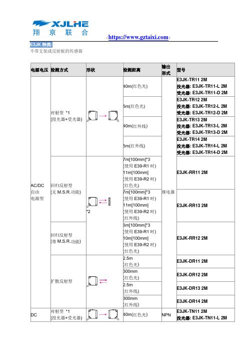
E3JK种类:不带支架或反射板的传感器电源电压检测方式形状检测距离输出形式型号AC/DC 自由电源型对射型*1(投光器+受光器)40m(红色光)继电器E3JK-TR11 2M投光器: E3JK-TR11-L 2M受光器: E3JK-TR11-D 2M5m(红色光)E3JK-TR12 2M投光器: E3JK-TR12-L 2M受光器: E3JK-TR12-D 2M40m(红外线)E3JK-TR13 2M投光器: E3JK-TR13-L 2M受光器: E3JK-TR13-D 2M5m(红外线)E3JK-TR14 2M投光器: E3JK-TR14-L 2M受光器: E3JK-TR14-D 2M回归反射型(无M.S.R.功能)*27m[100mm]*3(使用E39-R1时)11m[100mm](使用E39-R2时)(红色光)E3JK-RR11 2M7m[100mm]*3(使用E39-R1时)11m[100mm](使用E39-R2时)(红外线)E3JK-RR13 2M回归反射型(带M.S.R.功能)6m[100mm]*3(使用E39-R1时)10m[100mm](使用E39-R2时)(红色光)E3JK-RR12 2M扩散反射型2.5m(红色光)E3JK-DR11 2M300mm(红色光)E3JK-DR12 2M2.5m(红外线)E3JK-DR13 2M300mm(红外线)E3JK-DR14 2MDC 对射型*1(投光器+受光器)40m(红色光) NPNE3JK-TN11 2M投光器: E3JK-TN11-L 2M受光器: E3JK-TN11-D 2MPNP E3JK-TP11 2M投光器: E3JK-TP11-L 2M 受光器: E3JK-TP11-D 2M5m(红色光) NPNE3JK-TN12 2M投光器: E3JK-TN12-L 2M受光器: E3JK-TN12-D 2M PNPE3JK-TP12 2M投光器: E3JK-TP12-L 2M受光器: E3JK-TP12-D 2M40m(红外线) NPNE3JK-TN13 2M投光器: E3JK-TN13-L 2M受光器: E3JK-TN13-D 2M PNPE3JK-TP13 2M投光器: E3JK-TP13-L 2M受光器: E3JK-TP13-D 2M5m(红外线) NPNE3JK-TN14 2M投光器: E3JK-TN14-L 2M受光器: E3JK-TN14-D 2M PNPE3JK-TP14 2M投光器: E3JK-TP14-L 2M受光器: E3JK-TP14-D 2M回归反射型(无M.S.R.功能)*2 7m[100mm]*3(使用E39-R1时)11m[100mm](使用E39-R2时)(红色光)NPN E3JK-RN11 2MPNP E3JK-RP11 2M7m[100mm]*3(使用E39-R1时)11m[100mm](使用E39-R2时)(红外线)NPN E3JK-RN13 2MPNP E3JK-RP13 2M回归反射型(带M.S.R.功能) 6m[100mm]*3(使用E39-R1时)10m[100mm](使用E39-R2时)(红色光)NPN E3JK-RN12 2MPNP E3JK-RP12 2M扩散反射型2.5m(红色光)NPN E3JK-DN11 2MPNP E3JK-DP11 2M 300mm(红色光)NPN E3JK-DN12 2MPNP E3JK-DP12 2M 2.5m NPN E3JK-DN13 2M(红外线) PNP E3JK-DP13 2M300mm (红外线) NPN E3JK-DN14 2M PNP E3JK-DP14 2M*1. 对射型的标准价格、标准库存为投光器和受光器配套的产品。
