现代电源技术2-41
- 格式:ppt
- 大小:267.50 KB
- 文档页数:17
VR-Series+Switchgear ModernizationVacuum replacement circuit breakers Technical dataVR-Series+A powerful enhancement of a proven technology34568101214161820222426A brand new replacement vacuum circuit breakerA brand new replacement vacuum circuit breaker Eaton’s VR-Series + vacuum replacement circuit breakers are brand new from the ground up. These circuit breakers are not “retrofits”, and do not use any parts from the original air-magnetic circuit breakers. They are designed to replace the existing air-magnetic circuit breakers with little or no cell modifications, which, if required, are kept to a minimum and are reversible. VR-Series + circuit breakers take performance and reliability to new levels by incorporating a utility hardened mechanism and advanced lubrication and come with a standard three-year warranty.Reduce maintenance costs and downtime with reliable vacuum technologyMost power circuit breakers require maintenance and lubrication every two years and proper maintenance canrequire 6–8 man-hours per circuit breaker. Thanks to our advanced lubrication system that creates a protective layer betweenwearing surfaces, we have taken maintenance intervals to the next level. Coupled with our utility hardened mechanism and applied in normal applications as defined by IEEE Std C37.04™-1999,the VR-Series +circuit breaker will only require maintenance once every 10 years or 10,000 operations, whichever comes first. Both the mechanism and control components can be easily maintained and can take as little as an hour to service.Solve parts availability issues Replacement parts for oldair-magnetic circuit breakers are becoming harder to find and may not comply with the original manufacturer’s specifications. VR-Series + mechanism and control components arecompatible with Eaton’s VCP-W and VR-Series + circuit breakers and are current production items. This means that replacement parts are in stock andavailable, saving you time and money, should you ever need them. Additionally, spare parts inventory is considerably reduced because VR-Series + circuits breakers have 50% fewer parts than traditional air magnetic circuit breakers.Increased interrupting capabilityPower demands may have increased your available short current beyond your existing switchgear’s capabilities. VR-Series + circuit breakers along with the appropriate bus bracing upgrades can increase your switchgear’s interrupting capabilities in the same space as your original air-magnetic circuit breakers. This provides a cost-effective alternative to a complete switchgear replacement.Eliminate arc chutesArc chutes degrade with usage and must eventually be replaced. VR-Series + circuit breakers use sealed vacuum interrupters and do not require arc chutes. Arc chutes raise environmental and legal issues due to asbestos.Designed and tested to exceed current IEEE/ANSI standards All VR-Series + medium-voltage circuit breakers are designed and tested to meet or exceed IEEE/ ANSI C37.59™-2018 standards. This assures compatibility with existing installations and IEEE/ ANSI application guidelines. IEEE/ANSI certification and certified factory production test reports are available.Available for vintage Westinghouse, General Electric, Allis-Chalmers (Siemens-Allis), ITE (BBC, ABB), and Federal Pacific Electric power circuit breakersVR-Series +A powerful enhancement of a proven technologyKey featuresRemote rotary racking system: Remote power racking devices, like Eaton’s RPR-2.1, may be used on circuit breakers with screw racking mechanisms to remove the operator from the arc-flash boundaryAssembled and tested in an ISO 9001:2015 certified facility: Ensuring the highest production quality for all VR-Series + circuit breakersNon-sliding conical current transfer: Eliminates Holm Effect and reduces hot spotsReliable TMF vacuum technology with copper-chromium contacts: This minimizes contact erosion andhot spotsArcT-cutout wear and wipeindicator: Requires no specialized tools to check for potential contact erosionCloSure™ mechanism health check: A simple yet extremely effective test used periodically to monitor mechanism’s healthEnhanced motor disconnect cut-off cam: Allows positive initia-tion of the limit switch and prevents damage to the switch, increasing breaker reliability63kA closing system: Hardened main-link roller and cam with a sealed aircraft grade bearing to ensure long life Solid spring disk: A robust design that eliminates lamination spread on the anti-reverse system and maximizes circuit breaker service lifeInsulated ring tongue terminals: On all wiring points with no splices for added reliability and ease of maintenanceSURE CLOSE MOC operator: Guaranteed not to stall the circuit breaker during closing and prevents damage to the existing cell MOC componentsEaton’s dedicated engineering team and continuous improvement processes have increased the circuit breaker’s reliability for optimum performance and reduced maintenance intervals. Each VR-Series + circuit breaker is equipped with a robust operating mechanism and reliable vacuum interrupter technology; built to exceed expectations.Disclaimer of warranties and limitation of liabilityThe information, recommendations, descriptions and safety notations in this document are based on Eaton’s experience and judgment and may not cover all contingencies. If further information is required, an Eaton sales office should be consulted. Sale ofthe product shown in this literature is subject to the terms and conditions outlined in appropriate Eaton selling policies or other contractual agreement between Eaton and the purchaser.THERE ARE NO UNDERSTANDINGS, AGREEMENTS, WARRANTIES, EXPRESSED OR IMPLIED, INCLUDING WARRANTIES OF FITNESS FOR A PARTICULAR PURPOSE OR MERCHANTABILITY, OTHER THAN THOSE SPECIFICALL Y SET OUT IN ANY EXISTING CONTRACT BETWEEN THE PARTIES. ANY SUCH CONTRACT STATES THE ENTIRE OBLIGATION OF EATON. THE CONTENTS OF THIS DOCUMENT SHALL NOT BECOME PART OF OR MODIFY ANY CONTRACT BETWEEN THE PARTIES.In no event will Eaton be responsible to the purchaser or user in contract, in tort (including negligence), strict liability or other-wisefor any special, indirect, incidental or consequential damage or loss whatsoever, including but not limited to damage or loss of use of equipment, plant or power system, cost of capital, loss of power, additional expenses in the use of existing power facilities, or claims against the purchaser or user by its customers resulting from the use of the information, recommendations and descriptions contained herein. The information contained in this manual is subject to change without notice.m WARNINGIMPROPERLY INSTALLING OR MAINTAINING THESE PRODUCTS CAN RESULT IN DEATH, SERIOUS PERSONAL INJURY OR PROPERTY DAMAGE.READ AND UNDERSTAND THESE INSTRUCTIONS BEFORE ATTEMPTING ANY UNPACKING, ASSEMBLY, OPERATION OR MAINTENANCE OF THE CIRCUIT BREAKERS.INSTALLATION OR MAINTENANCE SHOULD BE ATTEMPTED ONLYBY QUALIFIED PERSONNEL. THIS INSTRUCTION BOOK SHOULD NOTBE CONSIDERED ALL INCLUSIVE REGARDING INSTALLATION OR MAINTENANCE PROCEDURES. IF FURTHER INFORMATION IS REQUIRED, YOU SHOULD CONSULT EATON’S ELECTRICAL SERVICES & SYSTEMS.THE CIRCUIT BREAKERS DESCRIBED IN THIS BOOK ARE DESIGNED AND TESTED TO OPERATE WITHIN THEIR NAMEPLATE RATINGS. OPERATION OUTSIDE OF THESE RATINGS MAY CAUSE THE EQUIPMENT TO FAIL, RESULTING IN DEATH, BODILY INJURY AND PROPERTY DAMAGE.ALL SAFETY CODES, SAFETY STANDARDS AND/OR REGULATIONS AS THEY MAY BE APPLIED TO THIS TYPE OF EQUIPMENT MUST BE STRICTLY ADHERED TO.THESE VACUUM REPLACEMENT CIRCUIT BREAKERS ARE DESIGNED TO BE INSTALLED PURSUANT TO THE AMERICAN NATIONAL STANDARDS INSTITUTE (ANSI). SERIOUS INJURY, INCLUDING DEATH, CAN RESULT FROM FAILURE TO FOLLOW THE PROCEDURES OUTLINED IN THIS MANUAL.This product was manufactured by Eaton at the Power Breaker Center (PBC): 310 Maxwell Avenue, Greenwood, SC 29646.All possible contingencies which may arise during installation, operation or maintenance, and all details and variations of this equipment do not purport to be covered by these instructions. If further information is desired by purchaser regarding his particular installation, operation or maintenance of particular equipment,contact an Eaton representative.VR-Series + Replacement Circuit BreakerTable 1. AM-VR + availability and interchangeabilityExisting AM circuitbreaker type AM-VR +circuit breaker type a Maximum voltageNominal 3-phase MVA class Existing circuit breaker rated continuous current at 60 Hz Ratedvoltage factor Rated withstand ANSI test voltage Ratedshort-circuit Maximum sym. interrupting capability Closing and latching / momentary capabilities kV MVA Amps K Low freq.kV RMS Impulse kV peak IkA RMS KIkA RMS kA RMS / peak AM-150AM-VR +150 c 4.762501200 / 2000 1.241960293658 / 97AM-250AM-VR +250 4.762501200 / 2000 1.241960293658 / 97AM-150/250AM-VR +41 b c4.76N/A1200 / 20001.001960414178 / 132a All circuit breakers have a 3 second short-time and 3-cycle interrupting ratings.b Non-standard rating.cRequires bus bracing study and additional switchgear bracing.Allis-Chalmers AM-VR + 150/250Diagram and dimensions on next pageTable 2. Available AM-VR+ dimensionsCircuit breaker type Existing circuitbreaker ratedcontinuouscurrent at 60 Hz(Amps)A B C D EAM-VR+2501200 44.9921.507.0029.2540.39AM-VR+250200044.4021.507.0029.2540.39For detailed information please visit,/switchgearmodernizationVR-Series+ Replacement Circuit BreakerAllis-Chalmers FB/FC-VR+Table 3. FB/FC-VR+ availability and interchangeabilityExistingFB/FCcircuit breaker type FB/FC-VR+circuit breaker type aMaximumvoltageNominal3-phaseMVAclassExisting circuitbreaker ratedcontinuouscurrent at 60 HzRatedvoltagefactorRated withstandANSI test voltageRatedshort-circuitMaximum sym.interruptingcapabilityClosing andlatching /momentarycapabilities kV MVA Amps KLow freq.kV RMSImpulsekV peakIkA RMSKIkA RMSkA RMS /peakFB-500FB-VR+500 8.255001200 / 2000 1.253695334166 / 111 FC-500FC-VR+50015.05001200 / 2000 1.303695182337 / 62 FC-VR+500U c15.07501200 / 2000 1.303695283658 / 97FC-VR+41 b c15.0N/A1200 / 2000 1.003695414178 / 130a All circuit breakers have a 3 second short-time and 3-cycle interrupting ratings.b Non-standard rating.c Requires bus bracing study and additional switchgear bracing.Diagram and dimensions on next pageTable 4. FB/FC-VR+ dimensionsCircuit breaker type Existing circuitbreaker ratedcontinuous cur-rent at 60 Hz(Amps)A B C D E F GFB/FC-VR+ (All Ratings)1200 / 200080.6130.7510.0047.8732.2112.0031.00For detailed information please visit,/switchgearmodernizationVR-Series+ Replacement Circuit BreakerAllis-Chalmers MA-VR+Table 5. MA-VR+ availability and interchangeability ExistingMA circuit breaker type MA-VR+circuit breaker type aMaximumvoltageNominal3-phaseMVAclassExisting circuitbreaker ratedcontinuouscurrent at 60 HzRatedvoltagefactorRated withstandANSI test voltageRatedshort-circuitMaximum sym.interruptingcapabilityClosing andlatching /momentarycapabilities kV MVA Amps KLow freq.kV RMSImpulsekV peakIkA RMSKIkA RMSkA RMS /peakMA250MA-VR+250 4.762501200 / 2000 1.241960293658 / 97 MA250MA-VR+41 b c 4.762501200 / 2000 1.001960414178 / 132a All circuit breakers have a 3 second short-time and 3-cycle interrupting ratings.b Non-standard rating.c Requires bus bracing study and additional switchgear bracing.Diagram and dimensions on next pageTable 6. MA-VR + dimensionsCircuit breaker type Existing circuit breaker rated continuous current at 60 Hz (Amps)A B C D E F G H I MA-VR +1200 / 200066.3722.257.0033.3919.7312.0026.0011.8540.70For detailed information please visit,/switchgearmodernizationVR-Series+ Replacement Circuit BreakerAllis-Chalmers MC-VR+Table 7. MC-VR+ availability and interchangeability ExistingMC circuit breaker type MC-VR+circuit breaker type aMaximumvoltageNominal3-phaseMVAclassExisting circuitbreaker ratedcontinuouscurrent at 60 HzRatedvoltagefactorRated withstandANSI test voltageRatedshort-circuitMaximum sym.interruptingcapabilityClosing andlatching /momentarycapabilities kV MVA Amps KLow freq.kV RMSImpulsekV peakIkA RMSKIkA RMSkA RMS /peakMC500MC-VR+50013.85001200 1.33695182337 / 62 a All circuit breakers have a 3 second short-time and 3-cycle interrupting ratings.Diagram and dimensions on next pageTable 8. MC-VR + dimensionsCircuit breaker Type Existing circuit breaker rated continuous current at 60 Hz (Amps)A B C D E F G H I MC-VR +120079.7528.758.5042.4310.0033.0026.0011.8540.70For detailed information please visit,/switchgearmodernizationVR-Series+ Replacement Circuit BreakerFPE DST-2-VR+Table 9. DST-2-VR+ availability and interchangeabilityExisting DST-2 circuit breaker type DST-2-VR+circuit breakertype aMaximumvoltageNominal3-phaseMVAclassExisting circuitbreaker ratedcontinuouscurrent at 60 HzRatedvoltagefactorRated withstandANSI test voltageRatedshort-circuitMaximum sym.interruptingcapabilityClosing andlatching /momentarycapabilities kV MVA Amps KLow freq.kV RMSImpulsekV peakIkA RMSKIkA RMS kA RMS / peakDST-2-7.5-500DST-2-7.5-VR+5008.255001200 / 2000 1.253695334166 / 111 DST-2-15-500DST-2-15-VR+50015.05001200 / 2000 1.303695182337 / 62 DST-2-15-500U DST-2-15-VR+500U c15.05001200 / 2000 1.303695283658 / 97 DST-2-15-750DST-2-15-VR+75015.07501200 / 2000 1.303695283658 / 97 DST-2-15-500/750DST-2-15-VR+41 b c15.0N/A1200 / 2000 1.03695414177 / 130a All circuit breakers have a 3 second short-time and 3-cycle interrupting ratings.b Non-standard rating.c Requires bus bracing study and additional switchgear bracing.Diagram and dimensions on next pageTable 10. DST-2-VR+ dimensionsCircuit breaker type Existing circuitbreaker ratedcontinuous cur-rent at 60 Hz(Amps)A B C D E FDST-2-VR+1200 / 200065.3825.757.8834.1811.0019.81For detailed information please visit,/switchgearmodernizationVR-Series+ Replacement Circuit BreakerGE AM-VR+MagneblastTable 11. AM-2-VR+ availability and interchangeabilityExisting AM circuit breaker type AM-VR+circuit breaker type aMaximumvoltageNominal3-phaseMVAclassExisting circuitbreaker ratedcontinuouscurrent at 60 HzRatedvoltagefactorRated withstandANSI test voltageRatedshort-circuitMaximum sym.interruptingcapabilityClosing andlatching /momentarycapabilities kV MVA Amps KLow freq.kV RMSImpulsekV peakIkA RMSKIkA RMS kA RMS / peakAM4.16-150AM4.16-VR+150U c 4.761501200 / 2000 1.241960293658 / 97 AM4.16-250AM4.16-VR+250 4.762501200 / 2000 1.241960293658 / 97 AM4.16-250AM-4.16-VR+250 d 4.762502500 1.241960293658 / 97 AM4.16-250AM4.16-VR+41 b c 4.76N/A1200 / 2000 1.001960414178 / 132 AM7.2-500AM7.2-VR+5008.255001200 / 2000 1.253695334166 / 111 AM13.8-500AM13.8-VR+50015.05001200 / 2000 1.303695182337 / 62 AM13.8-500AM13.8-VR+500U c15.07501200 / 2000 1.303695283658 / 97 AM13.8-750AM-13.8-VR+750/750T e15.07501200 / 2000 1.303695283658 / 97 AM13.8-500AM-13.8-VR+41 b c15.0N/A1200 / 2000 1.003695414178 / 132a All circuit breakers have a 3 second short-time and 3-cycle interrupting ratings.b Non-standard rating.c Requires bus bracing study and additional switchgear bracing.d C ell modification including additional ventilation and cooling fans are required to achieve 2500 A rating.Consult factory for more information.e T he “T” denotes a Tall Frame and is not a General Electric Co. designation. The 750 and 750T designs are not interchangeable.Diagram and dimensions on next pageTable 12. Available AM-VR+ dimensionsCircuit breaker Type Existing circuit breaker ratedcontinuous current at 60 Hz (Amps)A B C D E F G HAM4.16-VR+2501200 / 200040.4323.13 6.0028.808.5017.9822.4518.25AM7.2/13.8-VR+5001200 / 200054.2132.949.7538.778.5017.9636.2526.80AM13.8-VR+7501200 / 200054.2132.949.7538.778.5017.9636.2526.80AM13.8-VR+750T1200 / 200062.2532.929.7538.938.5018.0044.2526.80 Can. AM13.8-VR+500120054.8132.529.7535.318.5018.3436.4829.14For detailed information please visit,/switchgearmodernizationVR-Series + Replacement Circuit BreakerTable 13. AMH-4.76-VR + availability and interchangeabilityExisting AM circuitbreaker typeAMH-4.76-VR +circuit breaker type a Maximum voltageNominal3-phase MVA class Existing circuit breaker rated continuous current at 60 Hz Ratedvoltage factor Rated withstand ANSI test voltage Ratedshort-circuit Maximum sym. interrupting capability Closing and latching / momentary capabilities kV MVA Amps K Low freq.kV RMS Impulse kV peak IkA RMS KIkA RMS kA RMS / peak AMH4.76-250AM4.16-VR +250 4.762501200 / 2000 1.241960293658 / 97AMH4.76-250AM4.16-VR +41 b c4.76N/A1200 / 20001.001960414178 / 132a All circuit breakers have a 3 second short-time and 3-cycle interrupting ratings.b Non-standard rating.cRequires bus bracing study and additional switchgear bracing.GEAMH-4.76-VR +Diagram and dimensions on next pageTable 14. AMH-4.76-VR + dimensionsCircuit breaker type Existing circuit breaker rated continuous current at 60 Hz (Amps)A B C D E F G H I J AMH-4.76-VR + 250/411200 / 200056.0223.447.0044.4240.077.5018.3826.508.5042.00For detailed information please visit,/switchgearmodernizationVR-Series+ Replacement Circuit BreakerGE VB1-VR+PowerVacTable 15. VB1-VR+ availability and interchangeability ExistingVB1 circuit breaker type VB1-VR+circuit breaker type aMaximumvoltageNominal3-phaseMVAclassExisting circuitbreaker ratedcontinuouscurrent at 60 HzRatedvoltagefactorRated withstandANSI test voltageRatedshort-circuitMaximum sym.interruptingcapabilityClosing andlatching /momentarycapabilities kV MVA Amps KLow freq.kV RMSImpulsekV peakIkA RMSKIkA RMSkA RMS /peakVB1-4.16-250VB1-VR+250 4.762501200 / 2000 1.251960293658 / 97 VB1-4.16-250VB1-VR+4.16-41 b c 4.76N/A1200 / 2000 1.001960414178 / 132 VB1-7.2-500VB1-VR+7.2-5008.255001200 / 2000 1.253695334166 / 111 VB1-13.8-500VB1-VR+13.8-500155001200 / 2000 1.303695182337 / 62 VB1-13.8-500VB1-VR+13.8-41 b c15N/A1200 / 2000 1.003695414178 / 132 VB1-13.8-750VB1-VR+750157501200 / 2000 1.303695283658 / 97 VB1-13.8-750VB1-VR+13.8-41 b c15N/A1200 / 2000 1.003695414178 / 132a All circuit breakers have a 3 second short-time and 3-cycle interrupting ratings.b Non-standard rating.c Requires bus bracing study and additional switchgear bracing.d All ratings were tested to multiple versions of IEEE C37.09 and can be rated as K=1 or K>1Diagram and dimensions on next pageTable 16. VB1-VR+ dimensionsCircuit breaker type Existing circuit breaker rated continuouscurrent at 60 Hz (Amps)A B C D E F GVB1-VR+1200 / 200032.7929.3129.2612.5010.9817.2331.00For detailed information please visit,/switchgearmodernizationVR-Series+ Replacement Circuit BreakerITEHK/VHK-VR +Table 17. HK/VHK-VR+ availability and interchangeabilityExistingHK/VHKcircuit breaker type HK/VHK-VR+ circuitbreaker type aMaximumvoltageNominal3-phaseMVAclassExisting circuitbreaker ratedcontinuouscurrent at 60 HzRatedvoltagefactorRated withstandANSI test voltageRatedshort-circuitMaximum sym.interruptingcapabilityClosing andlatching /momentarycapabilities kV MVA Amps KLow freq.kV RMSImpulsekV peakIkA RMSKIkA RMS kA RMS / peak5HK250 d5HK-VR+250 d 4.762501200 / 2000 1.241960293658 / 97 5HK250 d5HK-VR+41 b c d 4.76N/A1200 / 2000 1.001960414178 / 132 7.5HK500 d7.5HK-VR+500 d8.255001200 / 2000 1.253695334166 / 111 15HK500 d15HK-VR+500 d155001200 / 2000 1.303695182337 / 62 15HK500 d15HK-VR+41b c d15N/A1200 / 2000 1.003695414178 / 132 15HK750 d15HK-VR+750 d157501200 / 2000 1.303695283658 /97 15HK750 d15HK-VR+41 b c d15N/A1200 / 2000 1.003695414178 /132 5VHK250 e5VHK-VR+250 e 4.762501200 / 2000 1.241960293658 /97 5VHK250 e5VHK-VR+41 b c e 4.76N/A1200 / 2000 1.001960414178 / 132 5VHK250 f5VHK-VR+250 f 4.762501200 / 2000 1.241960293658 / 97 5VHK250 f5VHK-VR+41 b c f 4.76N/A1200 / 2000 1.001960414178 / 132 7.5VHK500 g7.5VHK+500 g8.255001200 / 2000 1.253695334166 / 111 15VHK500 g15VHK-VR+500 g155001200 / 2000 1.303695182337 / 62 15VHK500 g15VHK-VR+41 b c g15N/A1200 / 2000 1.003695414178 / 132 15VHK750 g15VHK-VR+750 g157501200 / 2000 1.303695283658 / 97 15VHK750 g15VHK-VR+41 b c g15N/A1200 / 2000 1.003695414178 / 132a All circuit breakers have a 3 second short-time and 3-cycle interrupting ratings.b Non-standard rating.c Requires bus bracing study and additional switchgear bracing.d Model 03e Model 05 (36” wide), Model 23 (36” wide)f Model 05, 20, and 40 (26” wide)g Model 20, and 05 (36” wide)Diagram and dimensions on next pageTable 18. Available HK/VHK-VR + dimensions (Model 03 and 05, 20, and 40 shown for 26” wide 5kV Switchgear)Circuit breaker type Existing circuit breaker rated continuous Current at 60 Hz (Amps)A B C D E F 5HK-VR +1200 / 200049.0023.327.0025.728.0015.58For detailed information please visit,/switchgearmodernizationVR-Series+ Replacement Circuit BreakerWestinghouse DH-VR+Table 19. DH-VR+ availability and interchangeability ExistingDH circuit breaker type DH-VR+Circuit breaker type aMaximumvoltageNominal3-phaseMVAclassExisting circuitbreaker ratedcontinuouscurrent at 60 HzRatedvoltagefactorRated withstandANSI test voltageRatedshort-circuitMaximum sym.interruptingcapabilityClosing andlatching /momentarycapabilities kV MVA Amps KLow freq.kV RMSImpulsekV peakIkA RMSKIkA RMS kA RMS / peak50DH15050DH-VR+150U c 4.761501200 1.241960293658 / 97 50DH25050DH-VR+250 4.762501200 1.241960293658 / 97 50DH25050DH-VR+41 b c 4.762501200 1.001960414178 / 132 75DH50075DH-VR+5008.255001200 / 2000 1.253695334166 / 111 150DH500150DH-VR+50015.05001200 / 2000 1.303695182337 / 62 150DH500150DH-VR+500U c15.07501200 / 2000 1.303695283658 / 97 150DH500150DH-VR+41 b c15.0N/A1200 / 2000 1.003695414177 / 130 150DH750150DH-VR+75015.07501200 / 2000 1.303695283658 / 97 150DH750150DH-VR+41 b c15.0N/A1200 / 2000 1.303695414177 / 130a All circuit breakers have a 3 second short-time and 3-cycle interrupting ratings.b Non-standard rating.c Requires bus bracing study and additional switchgear bracing.Diagram and dimensions on next pageTable 20. Available DH-VR + dimensionsCircuit breaker type Existing circuit breaker rated continuous current at 60 Hz (Amps)A B C D E F 50DH-VR + 1200 64.3822.257.0032.619.0026.8175/150DH-VR +1200 / 200073.0732.3810.0044.389.0026.81For detailed information please visit,/switchgearmodernizationVR-Series+ Replacement Circuit BreakerWestinghouse DHP-VR +Table 21. DHP-VR+ availability and interchangeability ExistingDHP circuit breaker type DHP-VR+ circuitbreaker type aMaximumvoltageNominal3-phaseMVAclassExisting circuitbreaker ratedcontinuouscurrent at 60 HzRatedvoltagefactorRated withstandANSI test voltageRatedshort-circuitMaximum sym.interruptingcapabilityClosing andlatching /momentarycapabilities kV MVA Amps KLow freq.kV RMSImpulsekV peakIkA RMSKIkA RMS kA RMS / peak50DHP7550DHP-VR+75 4.76751200 1.3619608.81219 / 32 50DHP7550DHP-VR+75U c 4.76751200 1.241960293658 / 97 50DHEP25050DHEP-VR+250 4.762501200 / 2000 1.241960293658 / 97 50DHP25050DHP-VR+250 4.762501200 / 2000 1.241960293658 / 97 H50DHP25050DHP-VR+250H 4.762501200 / 2000 1.241960293678 / 132 50DHP25050DHP-VR+41 b c 4.76N/A1200 / 2000 1.001960414178 / 132 75DHP50075DHP-VR+5008.255001200 / 2000 1.253695334166 / 111 75DVP50075DVP-VR+5008.255001200 / 2000 1.253695334166 / 111 150DHP500150DHP-VR+500155001200 / 2000 1.303695182337 / 62 150DVP500150DVP-VR+500155001200 / 2000 1.303695182337 / 62 150DVP500150DVP-VR+500U c157501200 / 2000 1.303695283658 / 97 H150DHP500150DHP-VR+500H155001200 / 2000 1.303695182358 / 97 150DHP500150DHP-VR+500U c157501200 / 2000 1.303695283658 / 97 150DHP750150DHP-VR+750157501200 / 2000 1.303695283658 / 97 150DVP750150DVP-VR+750157501200 / 2000 1.303695283658 / 97 H150DHP750150DHP-VR+750H157501200 / 2000 1.303695283677 / 130 150DHP750C150DHP-VR+750C157501200 / 2000 1.303695283658 / 97 H150DHP750C150DHP-VR+750CH157501200 / 2000 1.303695283677 / 130 150DHP500/750150DHP-VR+41 b c15N/A1200 / 2000 1.003695414177 / 130a All circuit breakers have a 3 second short-time and 3-cycle interrupting ratings.b Non-standard rating.c Requires bus bracing study and additional switchgear bracing.Diagram and dimensions on next pageTable 22. Available DHP-VR + dimensionsCircuit breaker type Existing circuit breaker rated continuous current at 60 Hz (Amps)A B C D E F 50DHP-VR +1200 / 200048.7522.397.0027.408.5016.52For detailed information please visit,/switchgearmodernizationFollow us on social media to get the latest product and support information.Eaton is a registered trademark. All other trademarks are property of their respective owners.Eaton1000 Eaton Boulevard Cleveland, OH 44122United States © 2021 EatonAll Rights ReservedPublicaton No. BR182005EN / GG January 2021。
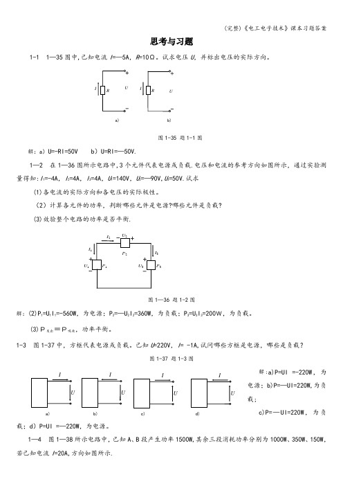
思考与习题1-1 1—35图中,已知电流I =—5A ,R =10Ω。
试求电压U ,并标出电压的实际方向。
图1-35 题1-1图解:a )U=-RI=50V b )U=RI=—50V.1—2 在1—36图所示电路中,3个元件代表电源或负载.电压和电流的参考方向如图所示,通过实验测量得知:I 1=-4A ,I 2=4A ,I 3=4A ,U 1=140V ,U 2=—90V,U 3=50V.试求(1)各电流的实际方向和各电压的实际极性。
(2)计算各元件的功率,判断哪些元件是电源?哪些元件是负载? (3)效验整个电路的功率是否平衡.图1—36 题1-2图解:(2)P 1=U 1I 1=-560W ,为电源;P 2=—U 2I 2=360W ,为负载;P 3=U 3I 3=200W,为负载。
(3)P发出=P吸收,功率平衡。
1-3 图1-37中,方框代表电源或负载。
已知U =220V ,I = -1A,试问哪些方框是电源,哪些是负载?图1-37 题1-3图解:a)P=UI =-220W ,为电源;b)P=—UI=220W,为负载;c)P=—UI=220W ,为负载;d )P=UI =—220W ,为电源。
1—4 图1—38所示电路中,已知A 、B 段产生功率1500W,其余三段消耗功率分别为1000W 、350W 、150W ,若已知电流I =20A,方向如图所示.a) b)Ia) b) c) d)(1)标出各段电路两端电压的极性。
(2)求出电压U AB 、U CD 、U EF 、U GH 的值。
(3)从(2)的计算结果中,你能看出整个电路中电压有什么规律性吗?解:(2) U AB =—75V,U CD =50V,U EF =17。
5V ,U GH =7.5V(3) U AB +U CD +U EF +U GH =0.1—5 有一220V 、60W 的电灯,接在220V 的电源上,试求通过电灯的电流和电灯在220V 电压下工作时的电阻。
目录直流电源系统技术标准 (1)直流电源系统技术监督规定 (24)直流电源系统评价标准(试行) (41)直流电源系统运行规范 (56)电力系统用蓄电池直流电源装置运行与维护技术规程 (81)通信用阀控式密封铅酸蓄电池 (96)中国移动行业蓄电池的维护标准 (105)中国电信行业蓄电池的维护标准 (108)通信用阀控式密封铅酸蓄电池技术要求和检验方法 (111)IEEE推荐用于站用阀控铅酸(VRLA)蓄电池的维护、测试和更换方法 (119)直流电源系统技术标准(附编制说明)1 总则1.1 为了适应电网发展要求,提高设备运行的安全可靠性,加强直流电源系统设备技术管理,特制定本技术标准。
1.2 本标准是依据国家和行业的有关标准、规程和规范并结合国家电网公司输变电设备评估分析、生产运行情况分析以及设备运行经验而制定的。
1.3 本标准对直流电源系统设备的技术条件、订货、监造、出厂验收、包装贮运、现场安装、现场验收、试验方法等提出了具体要求。
1.4 本标准适用于国家电网公司系统的发电厂、变电所及其他电力工程对直流电源装置的技术管理。
2 引用标准以下为输电设备设计、制造及试验所应遵循的国家、行业和企业的标准及规范,但不仅限于此:GB 13337.1-1991 固定型防酸式铅酸蓄电池技术条件GB/T 17626.2-1998 电磁兼容试验和测量技术静电放电抗扰度试验GB/T 17626.12-1998 电磁兼容试验和测量技术振荡波抗扰度试验DL/T 637-1997 阀控式密封铅酸蓄电池订货技术条件DL/T 5044-2004 电力工程直流系统设计技术规定DL/T 459-2000 电力系统直流电源柜订货技术条件DL/T 724-2000 电力系统用蓄电池直流电源装置运行与维护规程DL/T 5120-2000 小型电力工程直流系统设计规程DL/T 781-2001 电力用高频开关整流模块国家电网公司电力生产设备评估管理办法(生产输电[2003]95号)国家电网公司关于加强电力生产技术监督工作意见(生产输电[2003]29号)国家电网公司预防直流电源系统事故措施(国家电网生[2004]641号)3使用条件3.1 正常使用的环境条件3.1.1 海拔不超过1000m。

中国标准电源插头227IEC42(RVB)2× 0.5mm26A250V227IEC42(RVB)2×0.75mm62A250V227IEC52(RVV)2× 0.5mm26A250V× 0.75mm62A250V× 0.75m 6mA2250V × 0.75m 6mA2250V × 1.0mm120A250V227IEC52( RVV )3×0.5mm2 6A250V227IEC42(RVB)2227IEC42(RVB)2 227IEC52(RVV)2 227IEC52(RVV)2 × 0.5mm26A250V × 0.75mm62A250V × 0.5mm26A250V ×0.75mm62A250V227IEC52(RVV)2227IEC52(RVV) 2 227IEC53(RVV) 2 227IEC53(RVV) 2227IEC52( RVV)3× 0.75mm2 6A250V 227IEC53( RVV)3× 0.75mm2 6A250V227IEC53( RVV)3× 1.0mm2 10A250VRX 300/300V 3× 0.75mm2 6A250VRX 300/300V 3× 1.0mm2 10A250V欧洲标准电源插头H03VVH 2 -F 2X0.5mm2 10/16A250V H03VVH 2 -F 2X0.75mm2 10/16A250V H03VV -F 2X0.5mm2 10/16A250V H03VV -F 2X0.75mm2 10/16A250V H05VVH 2 -F 2X0.75mm2 10/16A250V H05VVH 2 -F2X1.0mm2 10/16A250V H05VV -F2X0.75mm210/16A250VRVV ) 227IEC52 0.5mm2 6A250V3× 227IEC52 RVV ) 3× 0.75mm2 6A250V 227IEC53 RVV ) 3× 0.75mm2 6A250V RVV ) 227IEC53 1.0mm2 10A250V 3×RVV ) 227IEC52 6A250V 3× 0.5mm2 227IEC52 RVV ) 3× 0.75mm2 6A250V 227IEC53 RVV ) 3×0.75mm26A250V227IEC53 RVV ) 3× 1.0mm2 10A250V2X1.0mm2H05VV -FH03VVH2 -F 2X0.5mm2H03VVH2 -F 2X0.75mm2H03VV -F 2X0.5mm2H03VV -F 2X0.75mm2H05VVH2 -F 2X0.75mm2H05VVH2 -F 2X1.0mm2H05VV -F 2X0.75mm2H05VV -F 2X1.0mm2H03VVH2 -F 2X0.5mm2H03VVH2 -F 2X0.75mm2H03VV -F 2X0.5mm2H03VV -F 2X0.75mm2H05VVH2 -F 2X0.75mm2H05VVH2 -F 2X1.0mm2H05VV -F 2X0.75mm2H05VV -F 2X1.0mm210/16A250V2.5A250V2.5A250V2.5A250V2.5A250V10A250V10A250V10A250V10A250V2.5A250V2.5A250V2.5A250V2.5A250V10A250V10A250V10A250V10A250VH03VV -F 3G0.5mm2H03VV -F 3G0.75mm210/16A250V10/16A250VH05VV -F 3G0.75mm2 10/16A250VH05VV-FH03VV -FH03VV -FH05VV -F227IEC52(RVV ) 3X0.75mm2 10A250V227IEC53(RVV) 3X0.75mm2 10A250V 227IEC53(RVV)3X1.0mm2 10A250V H03VV -F 3G0.75mm2 6A250VH05VV -F 3G0.75mm2 10A250V H05VV -F 3G1.0mm2 10A250V H05VV -F 3G1.0mm2 10/16A250VH05VV -F 3G1.5mm2 10/16A250V3G0.5mm2 10/16A250VH03VV -FH03VV -F 3G0.75mm2 10/16A250VH05VV -F 3G0.75mm2 10/16A250VH05VV -F 3G1.0mm2 10/16A250VH05VV -F 3G1.5mm2H03VV -F 3G0.5mm2H03VV -F 3G0.75mm210/16A250V10A250VH05VV -F 3G0.75mm2H05VV -F 3G1.0mm2 10A250V3G0.75mm23G0.75mm23G1.0mm2 10A250V3G0.5mm210A250V227IEC52(RVV) 3X0.75mm2 10A250V 227IEC53(RVV) 3X0.75mm2 10A250V227IEC53(RVV) 3X1.0mm2 10A250VH03VV -F 3G0.75mm2 6A250VH05VV -F 3G0.75mm2 10A250VH05VV -F 3G1.0mm2 10A250V澳大利亚标准电源插头SAAH05VVH2 -F 2X0.75mm2 7.5A250VH05VV -F 2X0.75mm2 7.5A250V10A250V H05VV -F 2X1.0mm2H05VVH2 -F 2X0.75mm2 7.5A250V H05VV -F 2X0.75mm2 7.5A250V H05VV -F 2X1.0mm2 10A250V3G0.75mm2 7.5A250VH05VV -FH05VV -F 3G1.0mm2 10A250VH05VV -F 3G1.5mm2 15A250V美国标准电源插头C-UL18AWG/2C 18AWG/2C 16AWG/2C 18AWG/2C 16AWG/2C 18AWG/2C 17AWG/2CNISPT-1NISPT-2 18AWG/2CSVT 18AWG/2C SVT 17AWG/2C ST 18AWG/2C ST 16AWG/2C SJT 18AWG/2C SJT 16AWG/2C NISPT-1 18AWG/2C NISPT-218AWG/2C18AWG/2C17AWG/2C 18AWG/2C (齿形 )17AWG/2C (齿形 )18AWG/2CSPT-1 SPT-2 SPT-2 SPT-3 SPT-3 SVT SVTSVT SVT SVT SVT ST ST18AWG/2C16AWG/2CSPT-118AWG/3CSPT-2 18AWG-16AWG/3CSPT-3 18AWG-16AWG/3CSVT 18AWG- 17AWG/3CSVT 18AWG-17AWG/3C(齿形)ST 18AWG-16AWG/3CSJT 18AWG-16AWG/3CSVT 18AWG/3CSVT 17AWG/3CSVT 18AWG/3C(齿形)SVT 17AWG/3C(齿形)ST 18AWG/3CST 16AWG/3CSJT 16AWG/3CSJT 18AWG/3C日本标准电源插头VFF 2X0.75mm2VCTF 2X0.75mm2VCTFK 2X0.75mm27A125V7A125V7A125V以色列南非英国电源插头H03VV-FH05VV-FH05VV-F3G0.75mm23G0.75mm23G1.0mm2H05VV-F 3G1.5mm2H03VV-FH05VV-FH05VV-FH05VV-F3G0.75mm23G0.75mm23G1.0mm23G1.5mm2H03VV-FH03VV-F3G0.5mm23G0.75mm2欧洲标准电源线3G0.75mm2 3G1.0mm2 3G1.5mm2认证国家名称代号H05VV-F H05VV-F H05VV-F· 标准: DIN VDE0281· 型号: H03VVH2-F H03VV-FH05VVH2-F H05VV-F· 额定电压: H03 300/300VH05 300/500V· 应用: H03 型适用小功率家用电器、电动工具及动力照明等。


TECHNOLOGY AND INFORMATION数据中心电源技术的应用及发展研究孙发杰 中国能源建设集团广东省电力设计研究院有限公司 广东 广州 510663摘 要 电源技术是数据中心稳定运行的重要工具,有必要对这方面进行深入研究。
本文将数据中心电源技术作为研究对象,简单叙述其应用价值,从UPS技术、HVDC技术、高压直流技术3个方面,详细分析数据中心电源技术的具体应用,整理数据中心电源技术未来的发展方向,旨在为更多数据中心管理单位提供技术指导,提升电源技术的应用质量,为数据中心安全高效运营提供技术帮助。
关键词 数据中心;电源技术;技术应用Research on Application and Development of Data Center Power Supply TechnologySun Fa-jieChina Energy Engineering Group Guangdong Electric Power Design Institute Co., Ltd., Guangzhou 510663, Guangdong Province, ChinaAbstract Power supply technology is an important tool for the stable operation of data centers, and it is necessary to conduct in-depth research on this aspect. This paper takes data center power supply technology as the research object, briefly describes its application value, analyzes the specific application of data center power supply technology in detail from three aspects: UPS technology, HVDC technology and high-voltage DC technology, and sorts out the future development direction of data center power supply technology, aiming to provide technical guidance for more data center management units, improve the application quality of power supply technology, and provide technical help for the safe and efficient operation of data centers.Key words data center; power supply technology; technology application引言数据中心是海量数据存储、开发的重要场景,需要保证持续的稳定供电,避免因断电出现信息丢失,影响数据中心后续正常运营。



230D10NZ-D电源模块技术说明书共13页(包括封面)1/13目录第一章概述 (3)1前言 (3)2系统性能特点 (3)3模块的主要特点 (3)4模块的主要功能 (4)5技术指标 (5)第二章模块构成 (6)1模块的工作原理 (6)2模块外形尺寸 (6)3模块安装 (9)4操作说明 (10)第三章使用环境 (13)销售服务热线:177-****6500售后服务热线:180-****8778 2/13第一章概述1前言我公司研制开发的-D系列数字化电力电源,是专为电力系统研发的新型数字控制开关电源,模块采用全数字控制,与前几代相比其具有的显著特点是:体积更小,重量更轻,可靠性更高等。
输出额定电压为220V,配有CAN通信接口,配有标准RS-485接口,易于与自动化系统对接,适于电力及相关行业使用,无需对监控及底层等进行改造即可实现升级。
2系统性能特点模块化设计,N+1热备,可平滑扩容。
全智能设计,通过串行通信,可自动实现:模块的开/关机、充电方式转换、输出电压调节、输出限流点整定、转换同步等功能。
模块配有标准RS-485接口,方便接入自动化系统,实现“四遥”及无人值守。
模块可带电插拔,更换安全方便。
3模块的主要特点工作频率高,重量轻,体积小,可靠性高。
采用数字均流,并机不均流度<±3%。
模块内置直流输出隔离二极管,用户无需外设。
模块为LED数码管显示,分别设置运行、故障灯显示,确定按钮、上下调整按钮,操作简单。
4模块的主要功能4.1保护功能输出过压保护:输出电压过高对用电设备会造成灾难性事故。
为杜绝此类情况发生,我公司的数字电源模块设置过压保护功能,出现过压后模块自动锁死,显示屏显示故障信息,故障模块自动退出工作而不影响整个系统正常运行。
例如输出额定电压为220V的模块过压点为320±15VDC,为防止软件失效时造成损失,模块内设置硬件过压保护电路,防止输出电压过高。
输出限流保护:每个模块的输出功率受到限制,输出电流不能无限增大,因此每个模块输出电流最大限制为额定输出电流的1.1倍,如果超负荷,模块自动调低输出电压以保护模块。


1.机电能量转换:dt时间内磁能的变化d% =%dj +约由B + i A i B[dL AB(e r)/de r]dd r,由绕组A和B中变压器电动势从电源所吸收的全部电能加之运动电动势从电源所吸收电能的一半所组成;由运动电动势吸收的另外一半电能成为转换功率,成为机械功率。
产生感应电动势是耦合场从电源吸收电能的必要条件,产生运动电动势是通过耦合场实现机电能量转换的关键。
转子在耦合场中运动产生电磁转矩,运动电动势和电磁转矩构成一对机电耦合项,是机电能量转换的核心部分。
2.磁阻转矩:t=-0.5(L^-LJi2sin26r。
当转子凸极轴线与定子绕组轴线重合,此时气隙磁导最大,定义ea q & 丁此时定子绕组的自感为直轴电感L d;当转子交轴与定子绕组轴线重合,此时气隙磁导最小,定义此时定子绕组的自感为交轴电感%;因此在转子旋转过程中,定子绕组的自感将发生变化。
由于转子运动使气隙磁导发生变化而产生的电磁转矩称为磁阻转矩。
转子励磁产生的电磁转矩称为励磁转矩。
3.直流电机电磁转矩:主磁极基波磁场轴线定义为d (直)轴,d轴反时针旋转90。
定义为q (交)轴。
直流电动机的电枢绕组又称为换向器绕组,其特征:电枢绕组本来是旋转的,但在电刷和换向器的作用下,电枢绕组产生的基波磁场轴线在空间却固定不动。
在动态分析中,常将换向器绕组等效为一个单线圈,若电刷放在几何中性线上,单线圈的轴线就被限定在q轴,称为q轴线圈。
因q轴磁场在空间是固定的,当q轴磁场变化时会在电枢绕组内感生变压器电动势;同时它又在旋转,在d轴励磁磁场作用下,还会产生运动电动势,q轴线圈为能表示出换向器绕组这种产生运动电动势的效应,它应该也是旋转的。
这种实际旋转而在空间产生的磁场却静止不动的线圈具有伪静止特性,称为伪静止线圈,它完全反映了换向器绕组的特征,可以由其等效和代替实际的换向器绕组。
电磁转矩Q =,控制i/不变,改变勿即改变Q,线性控制良好。

电池充电发生的能量转换一、引言电池作为一种重要的能量储存和转换装置,在现代社会中发挥着重要作用。
电池的充电过程是能量转换的关键环节,通过将外部电能转化为化学能,实现电池内部化学反应的逆过程,从而使电池重新获得储存的能量。
本文将对电池充电发生的能量转换进行全面、详细、完整且深入地探讨。
二、电池充电的基本原理电池充电是指通过外部电源向电池内部输送电能,使电池内部发生化学反应,将电能转化为化学能的过程。
充电过程可以分为三个主要阶段:1. 第一阶段:恢复正极材料在充电的最初阶段,外部电源提供的电能使得电池正极材料中的离子重新回到原来的位置。
这个过程中,电池正极材料的化学结构逐渐恢复,同时释放出一部分电能。
2. 第二阶段:电解质重组在恢复正极材料之后,外部电源继续向电池内部输送电能。
这个阶段,电解质中的离子开始重新组合,形成新的化学物质。
这个过程中,电池内部的化学能进一步增加。
3. 第三阶段:负极材料重组在电解质重组完成之后,外部电源继续向电池内部输送电能。
这个阶段,电池负极材料中的离子重新回到原来的位置。
这个过程中,电池负极材料的化学结构逐渐恢复,同时释放出一部分电能。
三、电池充电的能量转换过程电池充电的能量转换过程可以用以下步骤来描述:1. 外部电源向电池提供电能外部电源通过电线将电能输送到电池的正极,正极接收到电能后,开始恢复正极材料的化学结构。
2. 正极材料的化学结构恢复正极材料中的离子开始重新回到原来的位置,这个过程中,一部分电能被释放出来。
3. 电解质中离子的重组正极材料的化学结构恢复之后,电解质中的离子开始重新组合,形成新的化学物质。
这个过程中,电池内部的化学能进一步增加。
4. 负极材料的化学结构恢复电解质中离子重组完成之后,外部电源继续向电池输送电能,电池负极材料中的离子重新回到原来的位置。
这个过程中,一部分电能被释放出来。
5. 电池重新获得储存的能量当电池内部化学反应的逆过程完成之后,电池重新获得储存的能量,可以继续供应电力或用于其他用途。

1.低电压器往常指工作在交,直流电压 1200V 以下的电路中起切换,通断,控制,保护,检测与调理作用的电气设施。
2.按所控制的对象, 电器可分为低压配电电器与低压控制电器两大类3.从构造上瞧, 电器一般由感测部分与履行部分两个基本部分构成4.电磁机构由吸引线圈与磁路两部分构成5.按衔铁的运动方式电磁机构可分为衔铁绕棱角转动衔铁绕轴转动衔铁直线运动三大类6.熔断器就是一种利用熔体的融化作用而切断电路的最先级的保护电路7.低压断路器又称作自动空气断路器; 主要由触头系统、操作系统、保护元件三大多数构成8.异步电动机泊车制动的方式有机械制动与电气制动两大类9.常用的电气制动方式有能耗制动与反接制动两种10.电气控制设施设计一般分为 3 个阶段初步设计, 技术设计与产品设计11.电气控制线路的设计主要有一般设计法与逻辑设计法12.电子时间继电器可分为晶体管式与数字式时间继电器13.FEND 功能指令作用在主程序结束, 输出刷新发生在输出映像存放器送到输出锁存器或履行完用户程序14.可编程控制器的扫描周期由履行用户程序时间、系统管理操作时间等要素15.可编程控制器有 9 此中止源, 其优先级按中止产生的先后与中止指针号的高低摆列16.OUT 指令不可以用于输入继电器17.按直流电源的性质变频器可分为电压型与电流型两种18.按控制方式分变频器可分 V/F 控制变频器, 转差频次控制与矢量控制3 大类19数控机一般由控制介质, 数控介质, 伺服介质, 机床本体及检测装置 5 个部分20计算机数控系一致般由程序、输入输出设施、计算机数控装置、可编程控制器、主轴驱动与伺服驱动21靠谱性指系统在规定条件下, 在规准时间内, 达成规定功能的能力22简述电磁机构中灭弧产生的机理及常用的一些灭弧措施?答: 当断路器或接触器触电切断电路时, 如电路中电压超出 10~12V 与电流超出 80~100mA, 在拉开的两个触点间的撞击电离、热电子发射与热游离使得体现大批朝阳极飞奔的电子流,出现激烈火花, 即“电弧”灭弧的举措 1磁吹式灭弧装置-直流 2 灭弧栅-沟通 3灭弧罩-沟通与直流灭弧 4 多断电灭弧23接触器的作用就是什么?依据构造特色, 如何划分交, 直流接触器?答: 接触器就是用来屡次接通与切断电动机或其她负载主电路的一种自动切换电路依据构造特色, 一般来说,直流接触器为单极或双级; 沟通接触器大多为三极24按物理性质继电器有哪些主要分类?它们各有什么用途?什么就是继电特征?答: 电压继电器, 电流继电器, 功率继电器, 时间继电器,温度继电器, 速度继电器等电压继电器的用途: 对电路进行过电压或欠电压的保护电流继电器的用途: 对电路进行过电流或欠电流的保护功率继电器的用途: 对电路的功率进行控制时间继电器的用途: 使履行元件延缓一段时间动作继电器的主要特色: 就是拥有跳跃性的输入-输出特征再把书上的 11 页答上25什么就是继电器的返回系数?将开释弹簧放松或拧紧一些, 对电流(或电压) 继电器的吸合电流(或电压)与开释电流(或电压)有何影响?答 k=x1/x2 ,k 称为继电器的返回系数 ,x2称为继电器的吸合值 ,x1称为继电器的开释值当拧紧时,x2与x1同时增大,K 也随之增大 , 放松时 ,k 减小26试论述速度继电器的工作原理?答: 速度继电器的转子的轴与被控电机的轴相连, 而定子空套在转子上。

设备工作环境卖方提供的电源设备安装在室内。
设备必须能在以下环境条件下平安可靠地正常运行。
(1) 0 -- +45C : 保证设备技术指标。
(2) +45C < t < +55C : 保证设备平安运行。
(3) 最大相对湿度95% 时:保证设备可靠工作。
铭牌、包装、运输、储存铭牌设备应有铭牌,铭牌的字迹必须清楚,并标有以下数据:a. 制造厂名b. 型号c. 重量〔kg〕d. 制造年e. 其他包装、运输设备必须用木板花箱包装,保证产品在运输及储存期间不致损伤;必须单台整机包装,具备防水、防潮、防晒等条件,不能散件包装运输到场后组装。
产品向上放置为正方向。
包装上应注明工程名称、站点名称、收货单位、收货联系人、发货站、制造厂名、产品规格型号等。
随同产品应具有装箱单、合格证、说明书、出厂试验记录。
储存产品在运输及储存时必须正方向放置。
第一章设备技术要求1.1 对设备设计、制造的一般要求为配合广东电网公司建设工程标准化设计要求,做到电力通信设备安装标准化,现对电网建设工程中安装使用的通信设备机柜〔屏〕做出如下规定:设备的总体机械结构,应充分考虑安装、维护的方便和扩充容量或调整设备数量的灵活性,实现硬件模块化。
应具有足够的机械强度和刚度,设备的安装固定方式应具有防振抗震能力,应保证设备经过常规的运输、储存和安装后,不产生破损变形。
投标方应提供设备的机械结构、品种规格及安装规程等方面的详细说明。
线缆在机架内排放的位置应设计合理,不得阻碍或影响日常维护、测试工作的进行。
所有的安装和维护操作均应在机架前面进行。
所供设备机架不装单元框的空位置应加装盖板,当机架或子架提供整体盖板时除外。
投标方提供的设备应满足下面所列各项技术指标的要求,具有状态显示、异常或超限时具备可闻、可视告警及远程传送的功能。
开放接口,便于接入机房监控系统。
印刷电路板要求如下:a. 所有印刷电路板均应防腐蚀。
b. 印刷电路板应作防潮处理。
一种超磁致伸缩换能器驱动电源的设计与实现耿金登;王水波;韩笑飞【摘要】设计并实现了一种高效率的稀土超磁致伸缩换能器驱动电源,使换能器和功放的阻抗匹配得到改善.利用开关管的导通与否控制脉冲信号,从而达到驱动换能器的目的.本电源主要配合稀土换能器应用于桥梁和大体积混凝土的超声无损检测领域.数次实际检测效果表明:该电源可以迅速、有效、稳定地驱动稀土超磁致伸缩换能器.【期刊名称】《现代电子技术》【年(卷),期】2007(030)004【总页数】3页(P1-3)【关键词】磁致伸缩;换能器;MOSFET开关管;高频变压器【作者】耿金登;王水波;韩笑飞【作者单位】长安大学,信息工程学院,陕西,西安,710064;长安大学,信息工程学院,陕西,西安,710064;长安大学,信息工程学院,陕西,西安,710064【正文语种】中文【中图分类】TN41;TP331 引言随着高性能的磁致伸缩材料的快速发展,由其制成的换能器的应用也越来越广泛,涉及到许多先进的民用技术领域和军用技术领域。
磁致伸缩换能器能够把大功率的电能转化为很强的超声波振动,发射大功率的超声波,用于金属探伤、水下物体探测、混凝土无损检测等。
由稀土超磁致伸缩材料制成的稀土换能器具有发射功率大、频率高,能量稳定、转换效率高、传播距离远、机械强度高,工作电压低等特点,目前已成功用于海军装备、油井探测、扬声器、噪声与振动控制系统、超声检测、海洋勘探与地下通讯等领域。
稀土超磁致伸缩换能器本身并不能独立工作,他需要与大功率驱动电源配合使用。
要产生超声波辐射,必须用驱动电源对其进行激励,给其提供持续的、稳定的能量。
这样一来,驱动电源就成了必不可少的模块,其性能的优劣将直接影响到稀土换能器的技术性能和可靠性。
本文主要研究一种高效的稀土超磁致伸缩换能器驱动电源,以便快速、稳定地驱动稀土换能器。
2 驱动电源的设计由于驱动电源的实际负载为换能器线圈。
对换能器的驱动实际上就是对换能器线圈的激励。