相图阅读器PhaseDiagramViewer-中国科学院金属研究所图书馆
- 格式:ppt
- 大小:4.54 MB
- 文档页数:27
金属材料相图及物理性能计算软件JMatPro V8.0JMatPro包含的合金类型JMatPro软件包含一系列宽范围的合金类型,目前可以计算的合金类型包含铝合金、镁合金、铸铁、不锈钢、高中低合金钢、钴合金、镍基合金、镍铁基合金、镍基单晶超合金、钛合金、锆合金、焊料合金(锡焊)、铜合金;JMatPro 的主要特点独一无二性可以毫不夸张的说,JMatPro是金属材料性能计算方面的独一无二的软件。
在美国能源部的National Energy Technology Laboratory决定采用此软件时,软件采购负责人R. Mohn 写到:“This purchase order is being issued to Sente Software Inc because there is no alternative since they are the manufacturer of JMatPro and, as such, is the only source of this software. No other vendor can supply this software. This software is the only reliable, commercially available software available to make calculations for stable and metastable phase equibria; solidification behavior and properties; thermo-physical and physical properties; phase transformations; chemical properties; and mechanical properties for number of nickel-based and iron-based superalloys…”快速和正确的计算能力JMatPro是以强大而稳定的热力学模型、热力学数据为核心技术和计算基础的,所有物理模型的建立都经过了广泛的验证,以确保材料性能计算的准确性。
知识点:相图与计算相图相图(phase diagram)被誉为材料工作者的“地图”,相图表示在一定条件下,处于热力学平衡状态的物质系统中平衡相之间关系的图形,又称平衡图、组成图或状态图。
相图上的每一点都反映了某一材料在一定温度压力条件下的平衡状态是由什么样的结构相组成的,以及各相的成分与含量。
相图同时也给出了当成分或温度等热力学参数改变时材料发生相变的信息,相图上不同相区之间的界线两侧代表了两种不同的相结构。
至今,人们已经积累了大量珍贵的实测相图数据,其中大部分被汇编成册,并得到广泛应用。
确定相图的原则是热力学上体系达到平衡态,但是实际上通过两相界所对应的热力学条件不一定都能够从一个相转变到另一个相。
不能达到的原因有两个,一个是需要的温度或压力条件太苛刻,以至于技术上很难实现;另一种可能是达到另一个平衡相所需要的时间太长,以至实际上不能发生,即动力学上的因素。
解决上述两种问题的方法常常是采用在反应时加催化剂或通过增加反应物的活性来降低反应所需的温度或压力及缩短反应时间。
相图计算及其优化相图计算就是运用热力学原理计算一个体系的相平衡关系和绘制相图。
材料的品种繁多,新材料层出不穷,已发表的相图资料严重不全。
同时,材料中大多包括多种化合物,多元相图对材料设计和制备具有重要的意义,但是绘制多元相图的工作量十分巨大。
20世纪70年代以来,利用计算机绘制相图已经成为一个新的学科,被称为CALPHAD (Calculation of phase diagram)。
即利用已知的n 元相图来绘制(n+1)元相图。
具体的做法是,根据热力学的定律及函数,结合体系的初始条件、最小自由能、化学势,确立在一定的温度和压力下某组分体系的平衡状态和结构相。
只要有足够的热力学数据和资料,从低组分体系的已知相图来推测高组分体系的未知相图在理论上和实际上均是可行的。
由于计算机计算远比设计做实验快速得多,可以任意设点,因此利用CALPHAD绘制相图可以大大节约人力、物力、财力和时间。
Nuclear GraphiteTaiju ShibataJapan Atomic Energy Agency,4002Narita-cho,Oarai-machi,Higashiibaraki,Ibaraki 311-1393,Japan1.INTRODUCTIONGraphite and carbon materials are used for fission and fusion reactors in the nuclear energy field.These materials have excellent mechanical and thermo properties at high temperatures,and are used as moderator and reflector to energetic neutrons produced in the reactors.In the fission reactors,they are used for structural components in gas-cooled reactors,i.e.CO 2gas-cooled reactors and helium gas-cooled reactors [1].The former CO 2gas-cooled reactors,Magnox reactors,and advanced gas-cooled reactors (AGRs)have been developed in the United Kingdom since 1950s.Graphite is used as moder-ators for neutrons in the reactor core,and graphite components are located to keep fuel rods in the reactors.The reactors can obtain high temperatures of CO 2gas of about 390 C (Magnox)and 635 C (AGR),which are used to generate electricity by a steam turbine system.The latter is high temperature gas-cooled reactors (HTGRs).The HTGRs are graphite-moderated and helium gas-cooled reactors,and they have been under development since 1960s.Graphite and carbon materials are used for in-core structural components,such as fuel blocks,reflectors,and core support structures.These blocks have different func-tions as the in-core components.HTGRs can provide high temperature of helium gas of about 950 C at the reactor outlet,which is applicable not only for power generation by gas and steam turbine systems but also for process heat source in a hydrogen production system [2].Inherent and passive safety features of HTGRs are also attractive ones.In the fusion energy field [3e 7],graphite and carbon materials are used for high-temperature plasma-facing components for fusion devices,e.g.JT-60of Japan AtomicEnergy Agency (JAEA)in Japan,TFTR in the United States,and JET in the EuropeanUnion.The application of carbon material in the ITER has been studied under the international cooperation.The application to the fusion field is summarized in a reference [3].This paper describes on the application of the graphite and carbon materials in the fission reactors,especially for the HTGRs.The functions of the in-core components,neutron irradiation effects on graphite,and R&D items are described.2.OUTLINE OF HTGR S2.1.Outline of HTGR Development in the WorldFor the development of the HTGRs,experimental and demonstration reactors had been constructed and operated in the Europe and the United States from 1960s to 1980s [1].The experimental reactors are Dragon (Euratom,20MW thermal power),A VR (Germany,15MW electric power),and Peach Bottom (USA,45MW electric power),and the demonstration reactors are Fort Saint Vrain (USA,330MW electric power)and THTR (Germany,300MW electric power).The HTGRs use multilayered ceramic-coated fuel particles (TRISO)about 1mm in diameter to keep the fission product gases within the particles.The graphite and carbon materials are used for the in-core structural components such as fuel blocks,reflector blocks,and core support structures.The temperature of the reactor coolant,helium gas,at the outside reactor vessel was more than 700 C.The power generation system by steam turbineHandbook of Advanced Ceramics./10.1016/B978-0-12-385469-8.00006-X 113Copyright Ó2013Elsevier Inc.All rights reserved.was demonstrated through the plant operation of these historical HTGRs[1].In1990s,the JAEA had developed the HTTR,thefirst HTGR in Japan,which is a test reactor with30MW thermal power[2,8].Prismatic block-type fuel elements are used in the HTTR.It was demonstrated in2004that the HTTR can produce high-temperature helium gas of about950 C at the reactor outlet for thefirst time in the worldwide HTGR developments[9].A long-term high-temperature operation test,50days of continuous operation with the outlet temperature of950 C,had been successfully carried out in 2010[10].The goal of the HTTR project is to demonstrate a thermochemical hydrogen production cycle,iodine-sulfur (IS)process,with nuclear heat from the HTTR.The VHTR is a promising candidate for the Generation-IV nuclear energy systems,and an international collabora-tion has been carried out through the GIF[11,12].Regarding the commercial HTGR/VHTR projects for individual country,the United States focuses on the next generation nuclear plant(NGNP),and China started the construction of high-temperature reactor-pebble-bed module(HTR-PM). The nuclear hydrogen development and demonstration (NHDD)project has been studied in Korea.JAEA has been carrying out R&Ds on the design of an original VHTR based on the technologies established through the HTTR construction and operation.JAEA’s design is for a prismatic block-type reactor,gas turbine high-temperature reactor300-cogeneration(GTHTR-300C)[13].It can generate electricity and produce hydrogen by the IS process.The material properties including irradiation effects of graphites,used for the in-core components of the HTGR/ VHTR,depend highly on raw materials and forming processes.It is necessary to evaluate the irradiation effects for individual graphite grade used for the in-core compo-nents.JAEA had established the material database of IG-110graphite,PGX graphite,and ASR-0RB carbon for the in-core components of the HTTR[14,15].The irradiation effects on the material properties of IG-110are included in the database[16].The design of graphite components for GTHTR-300C is based on the established IG-110material database.Chinese test reactor HTR-10with10MW thermal output uses IG-11graphite,unpurified grade of IG-110,for reflector blocks.IG-110will be also used for the Chinese HTR-PM reactors.There are also databases of irradiated material proper-ties for historical graphite grades of H-451of the United States and ATR-2E of Germany,for example,developed between1970and1980[17e19].They are historical grades,and it is difficult to obtain these graphites for the reactor components with commercial scale,now.On the other hand,recently,new grades of nuclear graphite, namely,IG-430,NBG-18,PCEA,etc.,are being developed, and the irradiation effects on the material properties of these grades are obtained[20].2.2.In-Core Graphite and Carbon Structures in the HTTRGraphite and carbon materials are used for the in-core components of the HTGRs in order to obtain high temper-ature of helium gas at the reactor outlet.The components are categorized based on their safety function,replaceability,etc. In the followings,the application of the graphite and carbon materials to the HTGR in-core components is described with reference to the design of the HTTR[8,15,16].The arrangement of graphite components in the HTTR is shown in Figure1[8].The reactor core consists mainly of hexagonal fuel blocks,control-rod guide blocks,and replaceable reflector blocks.The active core,which is2.9m in height and2.3m in diameter,consists of30fuel columns and seven control-rod guide columns.The active core is surrounded by replaceable reflector blocks and permanent reflector blocks and supported by the core support components.The graphite components are categorized into two kinds taking their safety function and replaceability into account [15].One is core graphite components,the other is core support components.These graphite components have different use and functions as follows:i)The core graphite components are replaced at regularinterval;on the other hand,the core-support graphite components are permanent components.ii)The core support components have more serious structural functions than the core graphite components. Therefore,the stress limit for the core support components is set to be more severe than that for the core graphite components.2.2.1.Core Graphite ComponentsThe fuel blocks are graphite hexagonal prisms with an array of fuel holes.The fuel blocks are360mm acrossflats and 580mm in height as shown in Figure2[8].Three dowel pins are installed on the top face,and they engage with dowel sockets in the bottom face of the block above. TRISO-coated fuel particles with UO2kernel are dispersed in the graphite matrix and sintered to form a fuel compact. Fuel compacts are installed in a fuel rod made of graphite, 34mm in outer diameter and577mm in length.Fuel rods are inserted into the vertical holes in fuel block.Coolant helium gas of the reactorflows through gaps between the holes and the rods.The fuel blocks are fabricated from the IG-110graphite, isotropicfine-grained nuclear grade.Table1shows typical thermomechanical properties of the IG-110graphite[8,15]. Control-rod guide blocks and replaceable reflector blocks have the same external shape as the fuel blocks.They are also fabricated from the IG-110graphite.Handbook of Advanced Ceramics2.2.2.Core Support Graphite ComponentsThe assembly of core support is also shown in Figure1[8]. The hexagonal hot plenum block array is made up of two axial layers.This structure provides lateral and vertical positioning and support of the core array.The hot plenum block assembly contains passages,which collect the primary coolantflow from the outlet of the columns and distribute it into the high-temperature plenum beneath the hot plenum blocks.These blocks are fabricated from grade PGX,medium-tofine-grained molded graphite.Table1 shows typical thermomechanical properties of the PGX graphite[8,15].The core support posts and seatsareFIGURE2Block-type fuel element of the HTTR[8].Replaceable reflector block (IG-110)Control rod guide block (IG-110)Fuel block (IG-110)Permanent reflector block (PGX)Hot plenum block (PGX)Support post (IG-110)Lower plenum block (PGX)Bottom block (PGX)Carbon block (ASR-0RB)Core graphite componentsCore support graphite componentsFIGURE1Arrangement of graphite components in the HTTR[8].Chapter|2.5Nuclear Graphitedesigned to structurally support the core and hot plenum block array.The posts and seats are made of the IG-110graphite with higher strength than the PGX graphite.The thermal insulation layer at the core bottom consists of three blocks:lower plenum block,carbon block,and bottom block.The main function of the carbon block,ASR-0RB carbon,is to keep the metallic core support structures below 500 C.Table 1shows typical thermomechanical properties of ASR-0RB carbon [8,15].The permanent reflector is a graphite structure surrounding the replaceable reflector and control-rod guide columns.The permanent reflector is an assembly of graphite blocks making 12circumferential segments and 8axial layers.These blocks are made of PGX graphite.2.2.3.Design Criteria for Graphite Components in the HTTR2.2.3.1.Outline of the Design CriteriaFor the construction of the HTTR,JAEA (formerly,JAERI)established the graphite structural design code [14].In this code,the ASME-CE-code draft for graphite core support structure,which was prepared in 1980but not established,was partially modified in the items of biaxial failure theory,buckling limit,and oxidation effect on the basis of the experimental data [8,15,16].The JAEA’s design code contains a set of material property data for the IG-110graphite,PGX graphite,and ASR-0RB carbon being used in the HTTR core.The specified minimum ultimate strength,Su,is determined from statistical treatment of strength data such that the survival probability is 99%at a confidence level of 95%,because the ultimate strength exhibits considerable statistical scatter.Table 2shows the Su values for graphites andcarbon specified in the structural design code [14,15].As per the environmental effect on the strength,both the increase of strength by neutron irradiation and the decrease of strength by oxidation are considered.On the other hand,the increases of strength by temperature and strain rate are not considered due to a conservative design viewpoint.For the requirements on the quality assurance of graphite and carbon materials for the in-core components,industry-wide standards for the raw material and process-ing have not been established.Hence,for the quality assurance of in-core components of the HTTR [21],it was carried out on the basis of the requirements from reactor design.Their quality has been controlled during production and after machining with respect to their properties and specifications.Figure 3shows the flow diagram of accep-tance test program for the manufacturing process of graphite and carbon components in the HTTR [15,21].2.2.3.2.Irradiation Effects on Graphite Material PropertiesFor the application of graphite materials to the in-core components,one of the important subjects is to take into account the neutron irradiation-induced property changes.The fundamental mechanisms on the irradiation effects on graphite were studied and summarized in references [22,23].However,the material properties of graphites are dependent highly on their grades based on raw materials and forming process.The irradiation effects on the graphite are also dependent on their grades.Here,the irradiation effects on the IG-110,as a reference of the nuclear grade of graphite,are briefly described based on the above mentioned design code for the HTTR [14].The properties,considering the irradiation effects,aretheHandbook of Advanced Ceramicsdimensional change,longitudinal elastic modulus,mean coefficient of thermal expansion,thermal conductivity, strength,and steady-state irradiation creep coefficient.In the design code for the HTTR,they are expressed in the graphical expressions of material property data as a function of fast neutronfluence about several irradiation tempera-tures.The design curves in the graphical expressions were determined based on the irradiation experimental results at the JMTR of JAEA,etc.2.2.3.2.1.Dimensional Change The irradiation-induced dimensional change is a fundamental neutron irradiation effect.Figure4shows the relative dimensional change of the IG-110as a function of fast neutronfluence for several irra-diation temperatures[14].It is used for the design of graphite components in the HTTR.The dimensional change depends on irradiation temperature.The dimensional change behavior at higher neutronfluence is expressed in Figure5[24].The curves in thisfigure are obtained by the intrapolation andFIGURE3Flow diagram of acceptance test program for manufacturing process of graphite and carbon components in the HTTR[15,21]. Chapter|2.5Nuclear Graphiteextrapolation of the experimental data with evaluation.Generally,at the first stage of the irradiation,the bulk of the graphite is in shrinkage.This mechanism is expressed based on the irradiation behavior of grain and pore structure of graphite [22,23].For each graphite grain,the neutron irradi-ation causes expansion in c-axis direction and shrinkage in the a-axis direction.The expansion in the c-axis direction is accommodated by pores among the grains,since nuclear graphites have about 20%of porosity in general.As a result,the bulk of the graphite,polycrystalline structure with grains and pores,shows shrinkage by the neutron irradiation at the first stage.When the neutron fluence is increased,the shrinkage is attained to the minimum point,“turn around”.Then,the dimensional change has turned out to be increased.It was explained that the residual stress given by the shrinkage process causes micro cracks in the bulk of graphite,and the cracks work to increase the dimensional change rate.The fast neutron fluence of the turn-around point depends on the graphite grade and irradiation temperature.For the IG-110graphite,it is about 2Â1026n/m 2(E >0.1MeV)at irradia-tion temperature of 600 C [24].2.2.3.2.2.Longitudinal Elastic Modulus Figure 6shows the change of longitudinal elastic modulus of the IG-110as a function of fast neutron fluence for several irradiation temperatures [14].The change in elastic modulus due to irradiation is calculated from the change of velocity of longitudinal ultrasonic wave and the un-irradiated value of the longitudinal elastic modulus.At the initial stage of the irradiation,as shown in the figure,the modulus is rapidly increased by the pinning effect of dislocations in graphite crystals [22,23].Then,at the next stage of the irradiation,the modulus is gradually increased by the irradiation-induced dimensional shrinkage,i.e.the decrease of porosity of graphite.2.2.3.2.3.Mean Coefficient of Thermal Expansion The change of the mean coefficient of thermal expansion of IG-110as a function of fast neutron fluence is shown in Figure 7for several irradiation temperatures [14].The mean coefficient of thermal expansion is increased at the initial stage of the irradiation and then is decreased by the irradiation.2.2.3.2.4.Thermal Conductivity Figure 8shows the change of the thermal conductivity of IG-110as a function of fast neutron fluence for several irradiation temperatures [14].The conductivity is rapidly decreased by the initial stage of the irradiation.Irradiation-induced defects reduce the mean free path of phonon,which dominates the thermal conduc-tivity of graphite [22,23].The lower irradiation temperature gives the greater decrease in the conductivity.It is because that high-temperature irradiation causes annealing recovery of irradiation-induced defects during the irradiation.–1.5%–1.0%IG-110–0.5%0.0%0.00.51.01.52.08006001000400Irradiation Temperature (°C)Fast Neutron Fluence (1025n/m 2, E>0.18MeV)R e l. D i m e n s i o n a l c h a n g e1200FIGURE 4Dimensional change of the IG-110as a function of fast neutron fluence [14].-3.0-2.5-2.0-1.5-1.0-0.50.00.51.01.5R e l. D i m e n s i o n a l C h a n g e (%)Fast Neutron Fluenc (x1026 n/m 2 , E 0.1MeV)FIGURE 5Dimensional change of the irradiated IG-110graphite obtained by interpolation and extrapolation of existing data [24].0.00.51.01.52.0123456760040010008001200Fast Neutron Fluence (10 n/m, E>0.18MeV)252(E 0 : Longitudinal elastic modulus at room temperature)(E : Longitudinal elastic modulus at high temperature)0R e l. Y o u n g ’s m o d ul u s c h a n g e (E /E –1)Irradiation Temperature (°C)IG-110FIGURE 6Change of longitudinal elastic modulus of the IG-110as a function of fast neutron fluence [14].Handbook of Advanced Ceramics2.2.3.2.5.Strength The change of the compressive and tensile strengths of IG-110graphite by fast neutron irradiation is shown in Figure 9[14].In this neutron irradia-tion range,the both strengths are increased by the irradiation.2.2.3.2.6.Steady-State Irradiation Creep Coefficient Irradiation-induced creep behavior is evaluated from the dimensional change due to irradiation with loaded condition.An irradiation-induced creep equation is expressed based on the model,which is the combination of the Maxwell model (steady-state irradiation creep)and the Kelvin model (tran-sient irradiation creep)[15].εc ¼asE 0f 1Àexp ðÀbg Þg þK sg (1)Here,εc :Irradiation induced creep strain s :Stress (MPa)g :Fast neutron fluence (Â1026n/m 2,E >0.1MeV)a,b:Transient irradiation creep parameters K :Steady irradiation creep coefficientE 0:Longitudinal elastic modulus before irradiation (GPa).Figure 10shows the steady-state irradiation creep coefficient of IG-110as a function of irradiation temperature [14].0.20.10.0–0.1–0.2–0.3(α : Mean coefficient of thermal expansion after irradiation from 20 °C to irradiation temperature)–(α0 : Mean coefficient of thermal expansion before irradiation from 20 °C to irradiation temperature)–FIGURE 7Change of mean coefficient of thermal expansion of IG-110as a function of fast neutron fluence [14].1.00.80.60.40.20.0K 0 : Thermal conductivity at irradiation temperature before irradiation K : Thermal conductivity at irradiation temperature after irradiationFIGURE 8Change of the thermal conductivity of IG-110as a function of fast neutron fluence [14].Chapter |2.5Nuclear Graphite3.R&D S FOR VHTR DEVELOPMENTS e of Graphite Components for Long Service LifeMechanical and thermo stability of in-core graphite components is important during their service life in reactor operation.The service life of the core graphite components in the HTTR is about 1.5Â1025n/m 2(E >0.18MeV)in the fast neutron fluence.It is possible to extend the service life for commercial reactors based on the in-core design.The service life of the core graphite components in the GTHTR-300C [13]is evaluated as the fast neutron fluence of about 5Â1025n/m 2(E >0.18MeV).For the prismatic block type reactor,graphite components are replaceable.The fuel graphite blocks in the GTHTR-300C will be replaced atevery four-year interval during the reactor operation.For Pebble bed-type reactors,the maximum fast neutron fluence may be in the order of 1026n/m 2(E >0.1MeV)in case that core graphite components are not replaced throughout the reactor lifetime.It is important to design the graphite components to bear the severe fast neutron irradiation.Since the in-core graphite components of the VHTR are used subject to severe condition,it is important to assess their structural integrity during the service life.Residual stress is accumulated in the graphite compo-nents by irradiation-induced dimensional change due to thermal gradient and neutron flux distribution within the component during the reactor operation.The lifetime of the graphite component is determined by the comparison of the residual stress and the stress limit.The allowable service life is determined so that the irradiation-induced residual stress does not exceed the limit [25].For the stress limit of the graphite components in the design standard of the graphite components in the HTTR,it is set as one-third of the specified ultimate minimum strength Su for the core graphite components,which are replaceable components [15].The graphite grade with high strength will give the high stress limit.It is important to use a graphite grade with high strength to use in the long service life.In this point,IG-110graphite used in the HTTR has enough high strength.On the other hand,the residual stress is evaluated by viscoelastic analysis taking uncertainty of in-core temper-ature and neutron irradiation condition into account [26].The evaluated residual stress,hence,contains some safety margin.It is possible to extend the allowable components lifetime by reducing the margin with reasonable way,if we can measure the residual stress directly.JAEA is devel-oping the nondestructive evaluation technique for the residual stress of graphite components by using a micro-indentation method.It uses the change of the indentation behavior loading/unloading at the residual stress conditionRelative strength = (Strength after irradiation)/(Mean strength before irradiation)0.81.01.21.41.61.82.00123R e l. c o m p r e s s i v e s t r e n g t h c h a n g e(a)IG-1100.81.01.21.41.61.82.0012R e l. t e n s i l e st r e n g t h c h a n g e(b)IG-110Fast Neutron Fluence (1025n/m 2, E>0.18MeV)Fast Neutron Fluence (1025n/m 2, E>0.18MeV)FIGURE9Changes of (a)compressive and (b)tensile strengths of IG-110graphite by fast neutron irradiation [14].FIGURE 10Steady-state irradiation creep coefficient of IG-110as a function of irradiation temperature [14].Handbook of Advanced Ceramicsof graphite.Since the indentation behavior is affected by the residual stress condition,it is possible to evaluate the stress from microindentation behavior.The details of this study are shown in references[27,28].3.2.Standard for the Graphite Components of VHTRFor the design of the graphite components in the HTTR,the graphite structural design code for the HTTR[14]and inspection standard of graphite for the HTTR[21]were applied.It was so because the general standard system for the HTGR had not been established at that time.Recently,to prepare the general standard system,a“special committee on research on preparation for codes for graphite components in HTGR”at Atomic Energy Society of Japan(AESJ)had established draft of standard for graphite components in HTGR(including VHTR)in March2009[29].In the United States,a subgroup in the American Society of Mechanical Engineers(ASME)is working to establish a new design code for graphite core components,which can be applicable to gas-cooled reactors including VHTR.For the establishment of the standard of the AESJ,the standards for the graphite components of HTTR and ASME were reviewed.The established standard is based on the HTTR graphite design code[14]and the inspection stan-dard of the graphite components for the HTTR[21].The established“draft of standard for graphite core components in high temperature gas-cooled reactor”is composed of(1) general rules,(2)design standard,(3)material and product standards,(4)in-service inspection and maintenance stan-dard,and(5)appendix and explanation.The graphite components are classified into three cate-gories(A,B,and C)in the standpoints of safety functions and replaceability.In the design section,the stress limits are determined by deterministic evaluation in principle.Alter-natively,it is possible to determine the stress limits by probabilistic evaluation with an appropriate fracture proba-bility.The general requirements for the in-service inspection and maintenance standard are determined.When a defect larger than a design assumption is found in graphite components by the in-service inspection,the cause shall be investigated,and the propriety of continuous use shall be judged by application of fracture mechanics,etc.As an appendix of the design standard,the graphical expressions of material property data of IG-110graphite as a function of fast neutronfluence are expressed.The graphical expressions were determined through the intra-polation and extrapolation of the irradiated data.The irra-diation data for historical grades H-451and ATR-2E were used for the evaluation of the intrapolation and extrapola-tion of irradiation data for IG-110.The details of the intrapolation and extrapolation method were reported in references[24,30].3.3.Development of Control RodMade of C/C CompositeThe control rods of HTGRs are used at severe temperature condition.At the reactor scram,control rods are immedi-ately installed into the reactor core with high temperature. For the HTTR,ferritic superalloy Alloy800H is used for the metal parts of the control rod[8].Its maximum allowable temperature to be used repeatedly after the scrams is900 C.On the other hand,for the VHTR,thermo condition of the core will be more severe than that of the HTTR.It is important to develop the control rod made of heat-resistant ceramics composite-material substitute for metallic materials.It is one of the major subjects for the VHTR development.The heat-resistant ceramic composite, C/C composite,and SiC/SiC composite are major candi-date materials for this purpose.Figure11shows the scheme of R&Ds at JAEA for the control rod made of C/C and SiC/SiC composites[31].The R&D items are categorized in the following phases:(1) database establishment,(2)design and fabrication,and(3) demonstration test in the HTTR.For the database establishment in phase(1),the data on material properties at un-irradiated and irradiated condi-tions are necessary.JAEA focuses especially on a two-dimensional C/C composite(2D-C/C composite)that has the layer structure of laminae composed offibers and matrix[32].Since the2D-C/C composite has great anisotropy in thermal and mechanical properties in parallel and vertical to lamina directions,it is important to take the anisotropy into account for design of the components. Neutron irradiation effects on the properties are also anisotropic and important.A PAN-based and plain-woven 2D-C/C composite,CX-270G grade,is one of the candidate materials for the control rod application.It is graphitized at (1) Database (C/C and SiC/SiC)Un-irradiation/ Irradiation experimentsstrength, elastic modulus, CTE,thermal conductivity, etc.(2) DesignControl rod structureDesign methodology(3) Demonstration by HTTRLarge component irradiationat primary helium-gas coolantwith temperature gradientEvaluation onirradiation effectsfor graphitizedC/C compositeInternationalcollaborationGraphiteirradiationdatabaseJAEAInternationalcollaboration FIGURE11Scheme of R&Ds on application of C/Ccomposite to control rod[31].For color version of thisfigure,the reader is referred to the online version of this book.Chapter|2.5Nuclear Graphite。

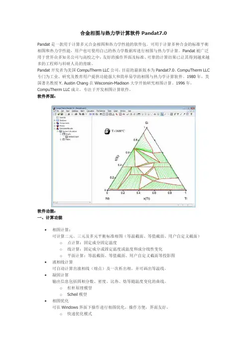
合金相图与热力学计算软件Pandat7.0Pandat是一款用于计算多元合金相图和热力学性能的软件包。
可用于计算多种合金的标准平衡相图和热力学性能,用户也可使用自己的热力学数据库进行相图与热力学计算。
Pandat被广泛用于世界众多知名公司与高校之中,友好的操作界面及标准、可靠的计算结果已让其得到越来越多的工程师与科研人员的青睐。
Pandat开发者为美国CompuTherm LLC公司,目前的最新版本为Pandat7.0。
CompuTherm LLC 专门为工业、研究及教育用户提供功能强大和简单易学的相图与热力学计算软件。
1980年,美国著名教授Y. Austin Chang在Wisconsin-Madison大学开始研究相图计算。
1996年,CompuTherm LLC成立,专注于开发相图计算软件。
软件界面:软件功能:一、计算功能∙相图计算:可计算二元、三元及多元平衡标准相图(等温截面、等值截面、用户自定义截面)o点计算:固定成分固定温度o线计算:固定成分或固定温度或温度和成分线性变化o平面计算:等温截面、等值截面、用户自定义截面等投影图∙液相线计算可自动计算出液相线(熔点)及一次析出相,并可画出等温线。
∙凝固计算输出信息包括固相分数、密度、比热、焓等随温度变化的曲线。
o杠杆原理模型o Scheil模型∙相图优化可在Windows界面下操作进行相图优化,操作方便,界面友好。
o快速优化模式o精确优化模式∙沉淀强化计算二、编辑功能∙文本编辑:支持在用户界面中进行数据库与批处理文件编辑∙表格编辑:o可在用户界面中进行图片信息与数据表格互换o可直接导入和输出excel表格数据o可在用户操作界面通过数据表格调出相关隐含数据(如自由能、焓等)∙图片编辑o可在图表区域中添加注释o可点击鼠标直接添加区域相组成o可在图表中直接绘制横线与相关图标三、高级功能∙支持批处理文件,可进行无人看守批处理计算∙支持PDB格式(Pandat公司数据库)和TDB格式(可用记事本编辑)数据库∙支持Pandat与PanEngine分离,PanEngine是动态链结函式库,它可用于制作用户特制的软件如凝固模拟,铸造模拟以及扩散计算等。
PeakView用法PeakView 是用于查看和处理质谱数据的强大工具。
以下是有关 PeakView 的详细用法说明。
一、简介PeakView 是 AB Sciex 公司开发的一款功能强大的生物信息学软件,主要用于处理和分析质谱数据。
它支持多种质谱数据格式,包括 .wiff、.dat、.txt 等,能够进行多维数据分析、谱图比较、肽质量指纹图谱分析等。
PeakView 的界面直观,操作简单,适合生物信息学、蛋白质组学和代谢组学等领域的研究人员使用。
二、数据导入与查看1. 打开 PeakView 软件,点击菜单栏上的“File”,在下拉菜单中选择“Open”,然后选择要导入的质谱数据文件。
2. 在弹出的窗口中选择数据文件类型和路径,点击“Open”按钮即可导入数据。
3. 导入数据后,可以在主界面上查看谱图。
可以通过鼠标滚轮放大或缩小谱图,也可以使用工具栏上的按钮进行操作。
4. 在谱图上右键单击,可以选择显示或隐藏不同维度的数据,如 XIC、TIC、Peaks 等。
三、数据分析1. 在菜单栏上选择“Processing”,在下拉菜单中选择“Multidimensional Viewer”,即可打开多维数据分析器。
2. 在多维数据分析器中,可以对数据进行聚类分析、主成分分析等操作,以便更好地了解数据特征和分布。
3. 在菜单栏上选择“Tools”,在下拉菜单中选择“Spectral Comparison”,即可进行谱图比较。
通过该功能可以比较不同样本或不同条件下的谱图差异。
4. 在菜单栏上选择“Analysis”,在下拉菜单中选择“Peptide Mass Fingerprint”,即可进行肽质量指纹图谱分析。
通过该功能可以预测蛋白质的氨基酸序列和分子量。
四、结果导出与可视化1. 在菜单栏上选择“File”,在下拉菜单中选择“Export”,然后选择要导出的数据类型和格式。
2. 在弹出的窗口中选择导出路径和文件名,点击“Save”按钮即可导出数据。
國立交通大學材料科學與工程學系碩士論文利用一階迴轉曲線及磁圓偏振光譜針對L10-FePt/Ni雙層膜翻轉行為之探討Reversal mechanism of L10-FePt/Ni investigated byfirst-order-reversal-curves and x-ray magnetic circular dichroism研究生:李一憲指導教授:曾院介博士中華民國一百零三年九月國立交通大學材料科學與工程學系碩士論文利用一階迴轉曲線及磁圓偏振光譜針對L10-FePt/Ni雙層膜翻轉行為之探討Reversal mechanism of L10-FePt/Ni investigated byfirst-order-reversal-curves and x-ray magnetic circular dichroism研究生:李一憲指導教授:曾院介博士中華民國一百零三年九月翻轉行為之探討Reversal mechanism of Ni/L10-FePt investigated byfirst-order-reversal-curves and x-ray magnetic circular dichroism研究生:李一憲Student:I-Hsien Lee指導教授:曾院介博士Advisor:Dr. Yuan-Chieh Tseng國立交通大學材料科學與工程學系碩士論文A ThesisSubmitted to Department of Materials Science and EngineeringCollege of EngineeringNational Chiao Tung Universityin partial Fulfillment of the Requirementsfor the Degree ofMasterinMaterials Science and EngineeringSeptember 2014Hsinchu, Taiwan, Republic of China中華民國一百零三年九月翻轉行為之探討研究生:李一憲指導教授:曾院介博士國立交通大學材料科學與工程學系(研究所)摘要近來,因磁記錄媒體密度需求不斷提升,具有高垂直磁晶異向性材料被廣泛地研究。
XRD物相检索的过程详解1检索的步骤先来说说检索的步骤,这只能是泛泛而谈了。
把数据读入JADE后,我一般不做任何处理就先检索物相,有人喜欢先平滑,但是,平滑的数据会失真,如果不是衍射图特别不好,建议不要先做平滑,当然也不要扣背景,扣Ka2了。
这样做的目的,只是为了最真实地找出物相来。
在按下S/M后,也会有一个提问,也是问要不要扣背景,也是回答N的。
鼠标的右键按下S/M,建议不要用左键按。
右键按下后会出现一个对话框,这里要做的主要是:选择PDF卡片数据库,我一般只选4个库,即无机物,矿物,ICSD无机物和ICSD矿物。
当然,如果你做陶瓷,则也应当加上陶瓷库。
第二个要选择的是要不要加入元素过滤器。
这是随时改变的。
一个样品第一次检索时,我一般懒得加元素限定条件,也就是不选择元素过滤器,让系统自动在全部卡片上过一遍,看看能否找得到所要的物相。
一般都能找出一个两个物相来,选上它。
返回到初始窗口。
右键再次按下S/M,打开条件对话框,加入元素限定条件。
加元素绝对不是一古脑儿都加进去,而是有意识,有步骤地加入。
检索的过程,我经常说是一个猜数的过程。
自己脑子里先有结果,然后再有意识地去找出来,得到验证。
现在很多人做掺杂,做合金的喜欢做大概有10种元素的合金,是否要一次性地把这些元素都加进去呢?肯定是不行的。
有些元素,加入量极微,起一些特殊作用,也形成新相,但是,这些相只有通过电子探针或TEM才能找得出来,用XRD是绝对检测不出来的,因此,在加入元素时,要考虑会形成什么样的相,才加入什么样的元素。
即使会形成量较多的相,但是,也不要全部加入,一次加入的元素原则上不超过4个,否则就起不到“元素限定”的作用。
?在的意识地加入某些元素后,再检索,可能会找到另外一些次要相。
在反复几次后,可能还有一些峰没有找到对应的物相,这时,先点一下“画峰按钮”(即求面积的按钮),在一个较强剩余峰下面划一下,即选定这个峰,再S/M,可能会找到与这个峰对应的物相。
金图外文数字图书馆使用帮助目录注意:请先下载安装KDF Reader阅读器 (2)如何通过分类查找图书 (5)如何通过检索查找图书 (8)如何阅读图书全文 (10)注意:请先下载安装KDF Reader阅读器本数字图书馆的图书文件为KDF格式,需要使用KDF reader阅读器阅读,请先进入下载页面下载并安装KDF reader阅读器。
1.点击网站顶端的【下载】按钮。
(红框处)2.在工具下载页面下方点击【KDF Reader】下载阅读器。
(红框处)3.选择保存,将阅读器安装文件保存到本地后解压缩再进行安装。
如何通过分类查找图书1.在网站左边栏是本库所使用的美国国会分类法。
2.点击分类名称前的加号可以展开该分类。
3.点击分类名称会在网页右边显示该分类的所有图书。
4.点击图书名称可以查看图书的详细信息,作者、出版社、ISBN等等。
点击【阅读全文】可以将图书下载到本地。
(注意:请一定将图书保存到本地再打开,在线打开是无法阅读图书的)点击【作者相关图书】可以查看该作者的其他图书。
点击【出版社相关图书】可以查看该出版社的其他图书。
如何通过检索查找图书1.网站左边栏的快速检索2.在文本框内输入检索词,下拉菜单中选择需要检索的项目,点击【GO】开始检索。
3.检索完成后会在网页右边显示检索结果,还可以在结果中再次进行检索,见红框处。
如何阅读图书全文1.请先安装KDF Reader阅读器,将图书下载到本地后,双击后缀名为KDF格式的图书即可打开。
或者是在阅读器中点击按钮来打开图书。
2.各功能按钮说明图书翻页功能图书的当前页数/总页数,可在文本框内输入数字来改变当前页书页宽度的显示方式全屏方式可隐藏菜单栏和工具栏,呈现方式可使用黑色背景阅读,双页显示可同时阅读2页将图书向左或向右旋转90度可进行文内查找放大或缩小图书的显示方式3.复制文本,在图书文本中按住鼠标左键拖拽一段文字后,对被选择的文字点击右键,在右键菜单中选择复制即可。
图象检视工具ImageViewer 6.1
佚名
【期刊名称】《电子与金系列工程信息》
【年(卷),期】2002(000)009
【总页数】1页(P17)
【正文语种】中文
【中图分类】TP311.56
【相关文献】
1.基于5E学习环和HP工具的数学实验创课设计——以“函数图象平移变换”的教学为例 [J], 黄一娉;黄梦远;唐剑岚;
2.人文与工具:大学语文教学构建的平衡点检视 [J], 刘金华;牛文倩
3.巧借"函数图象"工具理解电路"功率"问题 [J],
4.检视与重构:重大灾疫时期央、地扶持中小微企业财税工具的联动策略 [J], 曾远
5.检视与反思:工具理性视阈中的2018年《刑诉法》修改 [J], 吴卫军
因版权原因,仅展示原文概要,查看原文内容请购买。