Timing Analysis In Search of Multiple Paradigms
- 格式:pdf
- 大小:39.84 KB
- 文档页数:4
vhdl设计中的常见错误一Vhdl语言中1 提示:VHDL syntax error:expected choice in case statementCase语句中没覆盖到所有的情况,要加whe n others=> null;二.在verge hdl语句中在QuartusII下进行编译和仿真的时候,会出现一堆warning,有的可以忽略,有的却需要注意,虽然按F1可以了解关于该警告的帮助,但有时候帮助解释的仍然不清楚,大家群策群力,把自己知道和了解的一些关于警告的问题都说出来讨论一下,免得后来的人走弯路?下面是我收集整理的一些,有些是自己的经验,有些是网友的,希望能给大家一点帮助,如有不对的地方,请指正,如果觉得好,请版主给点威望吧,谢谢1. Found clock-sensitive change during active clock edge at time on register ""原因:vector source file中时钟敏感信号(如:数据,允许端,清零,同步加载等)在时钟的边缘同时变化。
而时钟敏感信号是不能在时钟边沿变化的。
其后果为导致结果不正确。
措施:编辑vector source file2. Verilog HDL assignment warning at : truncated value with size to match size of target (原因:在HDL设计中对目标的位数进行了设定,如:reg[4:0] a;而默认为32位,将位数裁定到合适的大小措施:如果结果正确,无须加以修正,如果不想看到这个警告,可以改变设定的位数3. AII reachable assignments to data_out(10) assign 'O', register removed by optimization原因:经过综合器优化后,输出端口已经不起作用了4. Follow ing 9 pi ns have nothing, GND, or VCC drivi ng datai n port -- cha nges to this conn ectivity may cha nge fitt ing results 原因:第9脚,空或接地或接上了电源措施:有时候定义了输出端口,但输出端直接赋’0'便会被接地,赋’1'接电源。
达·芬奇睡眠法达芬奇睡眠法(Da Vinci sleep),又称多阶段睡眠(Polyphasic_sleep)、Uberman睡眠或多相睡眠,是一种将人类习惯的单次睡眠过程分散成多个睡眠周期进行,以达成减少睡眠时间的睡眠方式。
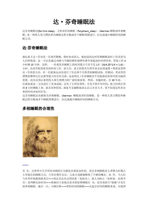
达·芬奇睡眠法画坛泰斗达·芬奇是一位刻苦勤勉、惜时如金的人,他创造的定时短期睡眠延时工作法甚为人们所称道。
这一方法是通过对睡与不睡的硬性规律性调节来提高时间利用率,即每工作4小时睡15分钟。
这样,一昼夜花在睡眠上的时间累计只有不足1.5(24/4.25*1/4 = 1.41)小时,从而争取到更多的时间工作。
前几年,意大利著名生理学家克拉胡迪奥·斯塔皮参照达·芬奇的方法,对一位航海运动员进行了长达两个月的类似睡眠试验。
经测试,受试者的逻辑思维和记忆运算等能力均完好无损。
这说明达·芬奇睡眠法不仅能满足机体代偿功能的需要,而且还预示着利用人体生理潜力的广阔发展前景。
然而,有趣的是,在20年前,一位画家就这一方法进行了亲身试验,证实了它的有效性。
可是不到半年时间,他又回到正常的8小时睡眠上来。
谈及各种原因,画家不无幽默地承认自己并非天才,更不知道这些多出来的时间该如何打发。
达芬奇睡眠法也被称为多相睡眠、Uberman睡眠或多阶段睡眠,是一种将人类习惯的单睡眠过程分散成多个睡眠周期进行,以达成减少睡眠时间的睡眠方式。
多相睡眠的合理性首先,自然界中几乎所有动物的行为都是多相复杂性的。
而且多相睡眠是人类婴儿时期占主导地位的睡眠方式,只有在稍年长后,儿童才逐渐被断绝了午睡的概念。
此外,当人们与外界环境隔绝联系后——保证无法从自然因素(如阳光),或人为暗示(如钟表、电视节目)来判断实际时间——将倾向于表现出更多的短暂睡眠行为,而非保持只“夜晚”才发生的单相睡眠。
最后一点,小睡打盹——即短时间的睡眠——比起长时间的睡眠来说,在提神醒脑方面更为有效。
单片机英语词汇Microcontroller English VocabularyIntroductionIn the field of electronics and embedded systems, microcontrollers play a vital role. Whether it's in consumer electronics, industrial automation, or Internet of Things (IoT) devices, microcontrollers are extensively used for controlling and monitoring various applications. This article aims to provide an overview of commonly used English vocabulary related to microcontrollers.1. MicrocontrollerA microcontroller is a miniature computer system on a single integrated circuit (IC). It consists of a central processing unit (CPU), memory, and input/output peripherals. Microcontrollers are designed for specific tasks and typically used in embedded systems where they control and interact with other electronic components.2. Embedded SystemAn embedded system is a combination of hardware and software designed for a specific function. It is integrated into a larger system and performs dedicated tasks. Microcontrollers are often at the heart of embedded systems, providing the intelligence and control required for the system to function.3. PeripheralA peripheral refers to an external device connected to a microcontroller. It allows the microcontroller to interact with the outside world, such as sensors, actuators, displays, and communication interfaces. Examples of peripherals include analog-to-digital converters (ADC), digital-to-analog converters (DAC), UART (Universal Asynchronous Receiver/Transmitter), and GPIO (General Purpose Input/Output) pins.4. InterruptAn interrupt is a signal generated by a peripheral or internal event that momentarily suspends the normal execution of the program. Interrupts allow critical tasks to be handled immediately, ensuring real-time responsiveness. Common types of interrupts include timer interrupts, external interrupts, and communication interrupts.5. FirmwareFirmware refers to software that is permanently stored on a microcontroller's memory and provides low-level control over its hardware peripherals. It is responsible for initializing the microcontroller, managing peripherals, and implementing specific functionalities. Firmware is typically written in assembly language or a high-level programming language like C.6. BitA bit, short for binary digit, is the smallest unit of digital information. It can represent either a 0 or a 1. Microcontrollers internally process data in terms of individual bits, allowing for precise control over binary operations. Bits are combined to form bytes, which are commonly used for data storage and manipulation.7. OscillatorAn oscillator generates a stable and accurate clock signal that provides timing for various operations within a microcontroller. The clock signal determines the speed at which the microcontroller executes instructions and controls the timing of data transfer. Common types of oscillators include crystal oscillators and ceramic resonators.8. Interrupt Service Routine (ISR)An Interrupt Service Routine (ISR) is a specific section of code that is executed when an interrupt occurs. It is responsible for handling the interrupt event and performing necessary actions. ISRs are typically written to respond to specific interrupt sources and can be customized based on the application's requirements.9. Serial CommunicationSerial communication is the process of transmitting data one bit at a time over a single data line. It is commonly used for communication between microcontrollers, sensors, and other peripherals. Serial communication protocols such as UART, SPI (Serial Peripheral Interface), and I2C (Inter-Integrated Circuit) are widely used in microcontroller-based systems.10. Real-Time Operating System (RTOS)A Real-Time Operating System (RTOS) is a specialized operating system designed for applications that require precise timing and responsiveness. RTOS provides task scheduling, resource management, and communication mechanisms tailored for real-time systems. It allows forconcurrent execution of multiple tasks and ensures critical tasks meet their timing deadlines.ConclusionIn conclusion, a thorough understanding of microcontroller-related English vocabulary is essential for professionals and enthusiasts working in the field of electronics and embedded systems. This article has provided a concise overview of key terms related to microcontrollers. By familiarizing yourself with these terms, you will be better equipped to communicate and comprehend technical documentation, participate in discussions, and deepen your knowledge in this exciting domain.。
计算机测量与控制.2020.28(11) 犆狅犿狆狌狋犲狉犕犲犪狊狌狉犲犿犲狀狋牔犆狅狀狋狉狅犾 ·54 ·收稿日期:20200629; 修回日期:20200720。
作者简介:杨 枫(1977),女,黑龙江哈尔滨人,硕士,高级工程师,主要从事载人航天器综合测试方案设计及仿真方向的研究。
文章编号:16714598(2020)11005405 DOI:10.16526/j.cnki.11-4762/tp.2020.11.012 中图分类号:V416文献标识码:A交会对接多航天器联合闭环测试模式设计与验证杨 枫1,2,任 亮1,2(1.南京航空航天大学航空宇航学院,南京 210016;2.中国空间技术研究院,北京 100094)摘要:在载人航天领域,多航天器交会对接技术是研制的关键和难题,闭环测试系统设计的重要性尤为突出,用于交会对接的多航天器联合闭环测试的设计与实施,实现了多航天器间的一体化实时动态同步电测,实现了多航天器及其测试系统的时序同步,以及敏感器及其模拟器和机电系统的动力学模型同步动态联合实时驱动的同步控制,采用了多航天器一体化实时精确控制的自动化测试,以及多航天器间多通道大回路信息流的实时统一管理;解决飞行任务阶段,多航天器交互状态的验证问题,在地面真实呈现交会对接飞行的全过程,达到多船器联合电测的目的。
关键词:交会对接;多航天器;闭环测试;同步一体化;测试系统设计;对接分离时序犇犲狊犻犵狀犪狀犱犞犲狉犻犳犻犮犪狋犻狅狀狅犳犑狅犻狀狋犆犾狅狊犲犱-犾狅狅狆犜犲狊狋犕狅犱犲犳狅狉犚犲狀犱犲狕狏狅狌狊犪狀犱犇狅犮犽犻狀犵犕狌犾狋犻狆犾犲犛狆犪犮犲犮狉犪犳狋YangFeng1,2,RenLiang1,2(1.DepartmentofAeronauticsandAstronauticsEngineering,NanjingUniversityofAeronauticsandAstronautics,Nanjing 210016,China;2.ChinaAcademyofSpaceTechnology,Beijing 100094,China)犃犫狊狋狉犪犮狋:Inthefieldofmannedspaceflight,multispacecraftrendezvousanddockingtechnologyisthekeyanddifficultproblemofdevelopment,andtheimportanceofthedesignofclosed-looptestsystemisparticularlyprominent.Thedesignandimplementa tionofjointclosed-looptestofmultispacecraftforrendezvousanddockingrealizestheintegratedreal-timedynamicsynchronouse lectricaltestofmultispacecraft,realizesthetimingsynchronizationandsensitivityofmultispacecraftanditstestsystemThedynamicmodelofthesimulatorandthemechanicalandelectricalsystemisdrivensynchronouslyanddynamicallyinrealtime.Theautomatictestoftheintegratedreal-timeprecisecontrolofmultiplespacecraftandthereal-timeunifiedmanagementofthemulti-channelandlargeloopinformationflowbetweenmultiplespacecraftareadopted.Tosolvetheproblemoftheverificationoftheinteractionstateofmultiplespacecraftinthemissionphase,andpresentthewholeprocessofrendezvousanddockingflightontheground,soastoachievethepurposeofjointelectricalmeasurementofmultiplespacecraft.犓犲狔狑狅狉犱狊:rendezvousanddocking;multispacecraft;closed-looptest;synchronousintegration;testsystemdesign;dockingseparationsequence0 引言在载人航天领域,多航天器交会对接技术是研制的关键和难题,交会对接闭环测试系统设计的重要性尤为突出,主要解决飞行任务阶段,多航天器交互状态的验证问题,突破了系统电测中多维度测试的关键技术,为顺利完成电测任务提出保障。

通信工程专业英语Revised at 16:25 am on June 10, 2021I hope tomorrow will definitely be better一、汉译英1、时分多址:TDMA Time Division Multiple Address/ Time Division Multiple Access2、通用无线分组业务:GPRSGeneral Packet Radio Service3、国际电报电话咨询委员会:CCITT4、同步数字体系:SDH Synchronous Digital Hierarchy 同步数字序列5、跳频扩频:FHSS frequency hopping spread spectrum6、同步转移模块:STM synchronous transfer module7、综合业务数字网:ISDNIntegrated Services Digital Network 8、城域网:MAN Metropolitan Area Network9、传输控制协议/互联网协议:TCP/IP Transmission ControlProtocol/Internet Protocol10、服务质量:QOS Quality of Service11、中继线:trunk line12、传输速率:transmission rate13、网络管理:network management14、帧结构:frame structure15、移动手机:Mobile Phone 手机Handset16、蜂窝交换机:Cellular switches 电池开关cell switchcell 蜂房17、天线:Antenna18、微处理器:microprocessor19、国际漫游:International roaming20、短消息:short message21、信噪比:SNRSignal to Noise Ratio22、数字通信:Digital communication23、系统容量:system capacity24、蜂窝网:cell networkcellular network Honeycomb nets 25、越区切换:Handover26、互联网:internet27、调制解调器:modem28、频谱:spectrum29、鼠标:Mouse30、电子邮件:electronic mail E-mail31、子网:subnet32、软件无线电:software defined radios33、网络资源:network resources二、英译汉1、mobile communication:移动通信2、Computer user:计算机用户3、Frame format:帧格式4、WLAN:wireless local area network 无线局域网络5、Communication protocol:通信协议6、Transmission quality:传输质量7、Remote terminal:远程终端8、International standard:国际标准9、GSM:全球移动通信系统Global System for Mobile Communications10、CDMA:码分多址Code Division Multiple Access11、ITU:国际电信联盟International Telecommunication Union12、PCM:pulse code modulation 脉冲编码调制13、WDM:波分复用Wavelength Division Multiplex14、FCC:联邦通信委员会Federal communications commission 15、PSTN:公用电话交换网Public Switched Telephone Network 16、NNI:网络节点借口Network Node Interface17、:万维网World Wide Web18、VOD:视频点播Video-On-Demand19、VLR:访问位置寄存器Visitor Location Register20、MSC:移动交换中心Mobile Switching Centre21、HLR:原籍位置寄存器Home Location Register22、VLSI:超大规模集成电路Very Large Scale Integrated Circuits23、Bluetooth technology:蓝牙技术24、Matched filter:匹配滤波器25、ADSL:非对称数字用户环路Asymmetrical Digital Subscriber Loop 非对称数字用户线路Asymmetric Digital Subscriber Line26、GPS:全球定位系统Global Position System27、ATM:异步传输模式Asynchronous Transfer Mode三、汉译英1、脉冲编码调制PCM依赖于三个独立的操作:抽样、量化和编码;PCM is dependent on three separate operations: sampling, quantizing and coding;2、像TCP和IP那样的协议已经被设计出来,当然,它们还需要被更新和维持;Protocols like TCP and IP have already been designed,of course,but they need to beupdated and maintained;3、码分多址是一种前景广阔的宽带数字工作系统;One form of digital wide band operation which has good future potential is CDMA;4、互联网是可提供很多网络资源的最大的信息库;The internet is the largest repository of information which can provide very largenetwork resources.5、开发蜂窝式移动电话系统并将其在许多城市中推广应用的原因之一是传统的移动电话系统存在容量有限、服务性能差、频谱利用率低的缺点;One of many reasons for developing a cellular mobile telephone system and deploying it in many cities is the operational limitations of conventional mobile telephone system;limited servile capability,poor service performance,and inefficient frequency spectrum utilization.6、来自发端借口不见的定时新号被加到数据调制解调器上,以使计算机与数传机同步;在接收端,从数据流中取出同步脉冲式计算机同步;Timing signals from the interface assembly at the transmitter are applied to the data modem to synchronize the computer and the data set. At the receivers synchronizationpulses are derived from the data stream to synchronize the computer.7、我们正处于通信网络革命的开始,越来越大的容量需求,各种各样的应用,以及服务质量正在对光网络提出巨大的需求;We are at the beginning of a revolution in communications networks, where increasing capacity, variety of applications, and quality of service are placing enormous demands on the optical network.8、目前在欧洲正在开发第三代移动通信系统,其目的是要综合第二代系统的所有不同业务并覆盖更广泛的业务话音、数据、视频、多媒体范围,而且还要与固定电话网络的技术发展保持一致和兼容;The third generation mobile communication system currently being developed in Europe, intended to integrate all the different services of the second generation system andcover a much wider range of broadband services Voice、data、video、multimediaconsistent and compatible with technology developments taking place within the fixed telecommunication networks.9、在现代对多媒体的描述中,我们所具有的技术已开始向人类具有的能力迈进;通过使用计算机技术、软件和其他技术,如CD-ROM;不仅能将视频图像和音频综合在一起,而且可以与其他计算机用户进行交互工作;In the modern presentation multimedia we now have the technology that can begin to move towards an ability already held by the human beings in that by using computer, technology, software and other technology, such as CD-ROM not only can we bring together audio and visual images but interactive with other computer users.10、为弥补这些问题,要在基本结构中加入大量的高效中继线;高效中继线用于直接连接有大量的节点间通信业务量的各交换中心;通信量常常是通过网络中可用的最低层次传送的;To compensate for these problems, a large number of high usage trunks augment the basic architecture. High-usage trunks are used for direct connection between switching centers with high volumes of internodes traffic. Traffic is always routed through the lowest available level of the work.11、光纤网络的革命刚刚开始,并正快速向未来的带宽无线、可靠和低费用的在线世界发展;The revolution of optical network is just beginning, and is advancing very swiftly towarda future online world in which bandwidth is essentially unlimited、reliable and low-cost.12、实际设备通常使用8kHz的采样速率,而如果每个样值用8位码的话,则话路是由一个重复速率64kHz的脉冲流来表示;Practical equipments, however, normally use a sampling rate of 8 kHz, and if 8 digits per sample value are used the voice channel becomes represented by a stream of pulses with a repetition rate of 64 kHz.13、是由于SDH设备在这些方面的标准化,才提供了网络运营者所期望的灵活性,从而能低价高效地应付带宽方面的增长并为后十年中出现的新的用户业务作好准备;It is the standardization of these aspects of SDH equipment that will deliver the flexibility required by network operators to cost effectively manage the growth in bandwidth and provisioning of new customer services expected in the net decade.四、英译汉1、The cellular concept is defined by two features, frequency reuse and cell splitting. Frequency reuse comes into play by using radio channels on the same frequency in coverage areas that are far enough apart not to cause co-channel interference. This allows handling of simultaneous calls that exceed the theoretical spectral capacity. Cell splitting is necessary when the traffic demand on a cell has reached the maximum=m and the cell is then divided into a micro-cellular system. The shape of cell in a cellular system is always depicted as a hexagon and the cluster size can be seven, nine or twelve. 蜂窝的概念由两个特点决定,频率复用和小区分割;在相邻覆盖区域足够远的而不至于引起共用信道干扰的,通过使用同一频率的无线信道,频率再利用才起作用;这样可以出来同时出现的呼叫并超出理论频谱容量;当小区的业务需求增到最大时,就要被划分,小区就要被划分成更小的蜂窝系统区域,蜂窝系统的小区形状常被描述成六边形,一群小区数量可以是9个或12个;2、Before you can use the Internet, you must choose a way to move data between the Internet and your PC. This link may be a high-speed data communication circuits, a local area network LAN, a telephone line or a radio channel. Most likely, you will use a Modem attached to your telephone line to talk to the Internet. Naturally, the quality of your Internet connection and service, like many other things in life, is dictated by the amount of money you are willing to spend.Although all these services can well satisfy the needs of the users for information exchange, a definite requirement is needed for the users. Not only should the users know where the resources locate, but also he should know some operating commands concerned.在使用Internet之前,必须使用一种方法在呢的PC机和Internet之间传递数据,这种连接的链路可以是高速数据通道电路,局域网,电话线路或无线信道;最有可能的是,你使用Modem连到电话线上与Internet对话;当然像生活中许多其他事物一样,与Internet连接服务和质量是由你花钱的数量来决定的;虽然这些所有的服务可以很好满足用户交换信息需要,但用户仍旧需要具有特定的先决条件,用户不但要知道信息资源的位置而且要知道一些有关的操作命令;3、Packet switching achieves the benefits discussed so far and offers added features. It provides the full advantage of the dynamic allocation of the bandwidth, even when messages are long. Indeed, with packer switching, many packets of the same message may be in transmission simultaneously over consecutive links of a path from source to destination, thus achieving a ‘pipelining’ effect and reducing considerably the overall transmission delay of the message as compared to message switching. It lends to require smaller storage allocation at the intermediate switches. It also has better error characteristics and leads to more efficient error recovery procedures, as it deals with smaller entities. Needless to say, packer switching presents design problems of its own, such as the need to reorder packets of a given message that may arrive at the destination node out of sequence.分组交换除具有以上讨论的有点之外,还具有一些特点;它提供带宽动态分配的全部优势,甚至当报文很长时依然如此,由于有分组交换,一个报文的多个分组确定可以通过原点到终点通路中多个链路同时传送,因而道道“管道”传送的效应,与报文交换相比,他大大的减少了报文整体传送时延;在中间交换设备中这种方式只需要较小的存储分配区域;分组交换的误码特性较好,由于它只涉及很短的长度,因而导致更高效的纠错方式;当然,分组交换也有自身设计上的麻烦,例如,当报文无序到达目的节点时,需要重新对该报文进行分组排序;4、As more and more systems join the Internet, and as more and more forms of information can be converted to digital form, the amount of stuff available to Internet userscontinues to grow. At some points very soon after the nationwide Internet started to grow, people began to treat the Net as a community, with its own tradition and customs.随着越来越多的系统连接到互联网,越来越多的信息被转化为数字形式,互联网用户可利用的资料持续增长,在不久的将来当国内互联网的规模增加到一定程度时,人们开始把互联网当做社区对待,并且拥有自己的传统和习惯;5、Three components are involved in a basic optical fiber system: the light source, the photo detector, and the optical transmission line. The optical light source generates the optical energy which serves as the information carrier, similar to a radio wave source supplying electromagnetic energy at radio wave wavelengths as the information carrier.The optical photo detector detects the optical energy and converts it into an electrical form. The optical fiber transmission line is the equivalent of copper wires and functionas the conductor of optical energy.基本的光纤系统涉及到3个部分:光源、光检测器和光缆;光源产生的能力作为信息的载体,类似于具有电磁能的无线电波用波长作为信息载体,光检测器检测光能并将其转化为电能的形式,光缆等效于铜线具有传导光能的作用;6、The fixed telephone service is global and the interconnection varies from coaxialcable to optical fiber and satellite. The national standards are different, but with common interfaces and interface conversion, interconnection can take place. For mobilethe problem is far more complex, with the need to roam creating a need for complex networks and system. Thus in mobile the question of standards is far more crucial to success than fixed systems.The GSM system is based on a cellular communications principle which was first proposedas a concept in the 1940s by Bell System engineers in the U.S. The idea came out of the need to increase network capacity and got round the face that broadcast mobile networks, operating in densely populated areas, could be jammed by a very small number of simultaneous calls. The power of the cellular system was that it allowed frequency reuse.全球范围内的固定电话通过同轴电缆、光缆和卫星相连;尽管各国的通信标准不同,但是由于有共同的接口和接口转换设备,互连问题得以解决;对于移动通信存在漫游问题,网络和系统就比较复杂,所以移动通信的标准问题就更关键;1940年有美国贝尔系统工程师提出的蜂窝通信原理是GSM系统的基础,其思路是在人口密集的区域由于一些同时发起的呼叫导致网络拥塞,采用蜂窝系统可以增加系统的容量,蜂窝系统的优点在于频率的重复利用;7、The advantage of SDH are mainly reflected in the following:1Lower network element costs: With a common standard, compatible equipment will be available from many vendors.In a highly competitive market prices will be vary attractive. 2 Better network management: With better network management, operators will be able to mote efficientlyuse the network and provide better service. The concept of TMNTelecommunication Management Networksis under study by CCITT. Some TMN standards defining management system interfaces already Faster provisioning: If new circuits can be software defined to use existing spare bandwidth then provisioning will be mush faster. The only new connection needed will be from the customer’s premises to the nearest network access node.SDH的优点是:1、较低的网络成本:由于具有共同的标准,许多供应商提供的设备可以兼容,激烈的时长竞争可以降低成本,2、更好的网络管理:运营商有能力提供更有效的业务,电信网管标准正在由CCITT指定,定义管理接口的相关标准已经出台;3、快速准备:如果新的电路可被软件来定义,利用现有的空闲频段从用户到最近的网络节点,接入的准备工作将更快;8、If we consider binary transmission, the complete information about a particular message will always be obtained by simply detection the presence or absence of the pulse. By comparison, most other forms of transmission systems convey the message information using the shape, or level of the transmitted signal; parameters that are most easily affected by the noise and attenuation introduced by the transmission path. Consequentlythere is an inherent advantage for overcoming noisy environments by choosing digital transmission.Noise can be introduced into transmission path in many different ways; perhaps via a nearby lightning strike, the parking of a car ignition system, or the thermal low-level noise within the communication equipment itself. It is the relationship of the truesignal to the noise signal, known as the signal-to-noise ratio, which is of most interest to the communication engineer.如果进行二进制传输,通过检测脉冲的有无就可获得报文的全部信息,相比之下,其他传输系统携带信息是通过波形和信号电平,这些参数容量收到噪声和传输信道衰减的影响,因此数字通信具有克服噪声环境的内在优势;噪声可能通过不同的方式进入传输信道,附近的闪电、汽车点火系统或者通信设备内部的热噪声,通信工程师最感兴趣的是信噪比;9、Most of the subscribers on the network ate telephones. The telephone contains a transmitter and receiver for converting back and forth between analog voice and analog electrical signals. With the introduction of the digital data system, some subscribers that transmit digital signals have been incorporated into the network.网络中大多数用户都是电话机;电话机包括一个送话器和一个受话器,用料在模拟话音和模拟电信号之间进行变换;随着数字、数据系统的引入,有些传输数字信号的用户已经并入该网;。
CONTENTSPXI Timing and Synchronization Modules Detailed View of PXIe-6674TKey FeaturesNI-Sync Application Programming Interface (API) Platform-Based Approach to Test and Measurement PXI InstrumentationHardware ServicesPXI Timing and Synchronization Modules PXIe-6674T, PXIe-6672, PXI-6683 and PXI-6683H•Generate high-stability PXI system reference clocks and high-resolution sample clocks •Minimize skew through access to PXI-star and PXIe-Dstar chassis trigger lines •Import and export system reference clocks for synchronization between multiple chassis orexternal devices •Achieve synchronization over large distance through GPS, IEEE 1588,IRIG-B or PPS•Develop advanced timing and sync applications with NI-Sync and NI-TClk softwarePowerful, Reliable Timing and SynchronizationNI’s PXI timing and synchronization modules enable a higher level of synchronization on the PXI platform through high-stability clocks, high-precision triggering and advanced signal routing. Implementing timing and synchronization hardware can vastly improve the accuracy of measurements, provide advanced triggering schemes, and allow synchronization of multiple devices for extremely high-channel-count applications. NI’s portfolio includes both signal-based and time-based solutions to deliver the advantages of synchronization to numerous applications.Table 1. NI offers various PXI modules to meet a range of timing and synchronization requirements.*Accuracy within one year of calibration adjustment within 0 ºC and 55 ºC operating temperature rangeDetailed View of PXIe-6674TSlot Compatibility PXI Timing or Peripheral Slot PXI or PXIe Hybrid Peripheral Slot PXIe System TimingSlot PXIe System TimingSlot Oscillator Accuracy*TCXO / 3.5 ppm TCXO / 3.5 ppm TCXO / 3.5 ppm OCXO / 80 ppb DDS Clock Generation Range Not available Not available DC to 105 MHz 0.3 Hz to 1 GHzDDS Clock Generation Resolution Not availableNot available0.075 Hz2.84 µHzPXI 10MHz Backplane Clock Override ● ● ● Clock Import Capability ● ● ● Clock Export Capability● ● ● ● Time-Based Synchronization (GPS, IEEE 1588, IRIG-B, PPS)● ● PXI Trigger Access (PXI_TRIG) ● ● ● ● PXI-Star Trigger Access (PXI_STAR) ●● ● PXIe-Dstar Trigger Access (PXI_DSTARA/B/C)● Front Panel Physical Connectors SMB, RJ45SMB, RJ45SMB SMA PFI Lines on Front Panel3366Key FeaturesHigh-Stability, High-Accuracy Onboard ClockApplications requiring highly reliable and consistent clock signals require a highly stable oscillator to avoid clock inaccuracies. For an NI PXI Express chassis, the oscillator is accurate to 25 parts per million (ppm). Inserting an NI PXI timing and synchronization module into the system timing slot of the chassis enables the user to replace this backplane system reference clock using the higher accuracy oscillator of the module. The PXIe-6672 and PXI-6683 modules contain a temperature-compensated crystal oscillator (TCXO) which can achieve accuracies better than 4 ppm. The PXIe-6674T features an oven-controlled crystal oscillator (OCXO) with an accuracy of 80 parts-per-billion (ppb). Note that the PXI-6683H contains the same oscillator as the PXI-6683, but due to its hybrid connectivity is not able to override the backplane clock.Figure 1.By referencing the OCXO on the PXIe-6674T, the 10 MHz backplane clock of a PXI chassis achieves muchlower phase noise and thus more clock stability.PXI modular instruments with phased-lock loop circuits, such as high-speed digitizers and waveform generators, can take advantage of the high-precision clock of timing and synchronization modules. When locking to a high-accuracy reference clock, the instrument inherits the accuracy of the clock, achieving sample clock resolutions as low as 0.5 Hz with an OCXO-based module.Skew Reduction with Star and Differential Star LinesDue to the variation in signal path lengths between slots in a PXI chassis, skew may be introduced when sending clocks or triggers to multiple slot destinations over the PXI trigger bus. To address this, all NI PXI chassis also include trace-length-matched star trigger lines accessible from a timing and synchronization module in the system timing slot. Star trigger lines can reduce skew to a maximum of 1 ns. Additionally, PXI Express chassis include differential star trigger lines capable of minimizing slot-to-slot skew to under 150 ps.Figure 2.While every slot of the PXI backplane may access the PXI trigger bus, the star trigger lines and differential star trigger lines are only accessible through the system timing slot.Time-Based Synchronization with GPS, IEEE 1588, IRIG-B or PPSThe NI PXI-6683 and PXI-6683H timing and synchronization modules synchronize PXI and PXI Express systems through time-based technology or protocols. Time-based modules can generate triggers and clock signals at programmable future times and timestamp input events with the synchronized system time including that of real-time systems. For PXI Express systems requiring time-based synchronization with backplane clock discipline or star trigger access, the PXI-6683H can be combined with the PXIe- 6674T or PXIe-6672 to provide a full-featured synchronization solution.Advanced Routing of Clocks and TriggersUsing a PXI timing and synchronization module provides the capability of advanced routing of clock and trigger signals. Through the combination of system timing slot access and FPGA-based routing, many more source-to-destination routes become possible, allowing more flexible designs and efficient use of system resources.Table 2. The PXIe-6674T timing and synchronization module features a wide vaiety of source-to-destination routes bycombining the power of the PXI Express architecture with the signal-routing capabilities of the onboard FPGA.● ● ● ● ● ● ● ● ● ● ● ● ● ● ● ● ● ● ● ● ● ● ● ● ● ● ● ● ● ● ● ● ● ● ● ● ● ● ● ● ● ● ● ● ● ● ● ● ● ● ● ● ● ● ● ● ● ● ● ● ● ● ● ● ● ● ●●●●●●●NI-Sync Application Programming Interface (API)The NI-Sync driver allows configuration of system timing and synchronization through LabVIEW, C, or .NET. This includes signal-based synchronization, such as sharing triggers and clocks to be used directly, or time-based synchronization, using time protocols such as IEEE-1588, IRIG, or GPS for non-tethered systems. NI-Sync is designed for use with other NI drivers, such as NI-DAQmx, for advanced timing, high channel count, distributed or multiple-instrument applications.DestinationS o u r c ePlatform-Based Approach to Test and MeasurementWhat Is PXI?Powered by software, PXI is a rugged PC-based platform for measurement and automation systems. PXI combines PCI electrical-bus features with the modular, Eurocard packaging of CompactPCI and then adds specialized synchronization buses and key software features. PXI is both a high-performance and low-cost deployment platform for applications such as manufacturing test, military and aerospace, machine monitoring, automotive, and industrial test. Developed in 1997 and launched in 1998, PXI is an open industry standard governed by the PXI Systems Alliance (PXISA), a group of more than 70 companies chartered to promote the PXI standard, ensure interoperability, and maintain the PXI specification.Integrating the Latest Commercial TechnologyBy leveraging the latest commercial technology for our products, we can continually deliver high-performance and high-quality products to our users at a competitive price. The latest PCI Express Gen 3 switches deliver higher data throughput, the latest Intel multicore processors facilitate faster and more efficient parallel (multisite) testing, the latest FPGAs from Xilinx help to push signal processing algorithms to the edge to accelerate measurements, and the latest data converters from TI and ADI continuallyincrease the measurement range and performance of our instrumentation.PXI InstrumentationNI offers more than 600 different PXI modules ranging from DC to mmWave. Because PXI is an open industry standard, nearly 1,500 products are available from more than 70 different instrument vendors. With standard processing and control functions designated to a controller, PXI instruments need to contain only the actual instrumentation circuitry, which provides effective performance in a small footprint. Combined with a chassis and controller, PXI systems feature high-throughput data movement using PCI Express bus interfaces and sub-nanosecond synchronization with integrated timing and triggering.OscilloscopesSample at speeds up to 12.5 GS/s with 5 GHz of analog bandwidth, featuring numerous triggering modes and deep onboard memoryDigital InstrumentsPerform characterization and production test of semiconductor devices with timing sets and per channel pin parametric measurement unit (PPMU)Frequency Counters Perform counter timer tasks such as event counting and encoder position, period, pulse, and frequency measurementsPower Supplies & Loads Supply programmable DC power, with some modules including isolated channels, output disconnect functionality, and remote senseSwitches (Matrix & MUX) Feature a variety of relay types and row/column configurations to simplify wiring in automated test systemsGPIB, Serial, & Ethernet Integrate non-PXI instruments into a PXI system through various instrument control interfaces Digital MultimetersPerform voltage (up to 1000 V), current (up to 3A), resistance, inductance, capacitance, and frequency/period measurements, as well as diode testsWaveform Generators Generate standard functions including sine, square, triangle, and ramp as well as user-defined, arbitrary waveformsSource Measure Units Combine high-precision source and measure capability with high channel density, deterministic hardware sequencing, and SourceAdapt transient optimizationFlexRIO Custom Instruments & Processing Provide high-performance I/O and powerful FPGAs for applications that require more than standard instruments can offerVector Signal Transceivers Combine a vector signal generator and vector signal analyzer with FPGA-based, real-time signal processing and controlData Acquisition Modules Provide a mix of analog I/O, digital I/O, counter/timer, and trigger functionality for measuring electricalor physical phenomena©2019 National Instruments. All rights reserved. LabVIEW, National Instruments, NI, NI TestStand, and are trademarks of National Instruments. Other product and company names listed are trademarks or trade names of their respective companies. The contents of this Site could contain technical inaccuracies, typographical errors or out-of-date information. Information may be updated or changed at any time, without notice. Visit /manuals for the latest information. Hardware ServicesAll NI hardware includes a one-year warranty for basic repair coverage, and calibration in adherence to NI specifications prior to shipment. PXI Systems also include basic assembly and a functional test. NI offers additional entitlements to improve uptime and lower maintenance costs with service programs for hardware. Learn more at /services/hardware .Program Duration 3 or 5 years3 or 5 years Length of service programExtended Repair Coverage●●NI restores your device’s functionality and includes firmware updates and factory calibration.SystemConfiguration,Assembly, and Test 1 ● ●NI technicians assemble, install software in, and test your system per your custom configuration prior to shipment.Advanced Replacement 2 ●NI stocks replacement hardware that can be shipped immediately if a repair is needed.System Return MaterialAuthorization (RMA)1 ●NI accepts the delivery of fully assembled systems when performing repair services.Calibration Plan (Optional) Standard Expedited 3NI performs the requested level of calibration at the specified calibration interval for the duration of the service program.1This option is only available for PXI, CompactRIO, and CompactDAQ systems.2This option is not available for all products in all countries. Contact your local NI sales engineer to confirm availability. 3Expedited calibration only includes traceable levels.PremiumPlus Service ProgramNI can customize the offerings listed above, or offer additional entitlements such as on-site calibration, custom sparing, and life-cycle services through a PremiumPlus Service Program. Contact your NI sales representative to learn more.Technical SupportEvery NI system includes a 30-day trial for phone and e-mail support from NI engineers, which can be extended through a Software Service Program (SSP) membership. NI has more than 400 support engineers available around the globe to provide local support in more than 30 languages. Additionally, take advantage of NI’s award winning online resources and communities .。

3GPP TS 36.331 V13.2.0 (2016-06)Technical Specification3rd Generation Partnership Project;Technical Specification Group Radio Access Network;Evolved Universal Terrestrial Radio Access (E-UTRA);Radio Resource Control (RRC);Protocol specification(Release 13)The present document has been developed within the 3rd Generation Partnership Project (3GPP TM) and may be further elaborated for the purposes of 3GPP. The present document has not been subject to any approval process by the 3GPP Organizational Partners and shall not be implemented.This Specification is provided for future development work within 3GPP only. The Organizational Partners accept no liability for any use of this Specification. Specifications and reports for implementation of the 3GPP TM system should be obtained via the 3GPP Organizational Partners' Publications Offices.KeywordsUMTS, radio3GPPPostal address3GPP support office address650 Route des Lucioles - Sophia AntipolisValbonne - FRANCETel.: +33 4 92 94 42 00 Fax: +33 4 93 65 47 16InternetCopyright NotificationNo part may be reproduced except as authorized by written permission.The copyright and the foregoing restriction extend to reproduction in all media.© 2016, 3GPP Organizational Partners (ARIB, ATIS, CCSA, ETSI, TSDSI, TTA, TTC).All rights reserved.UMTS™ is a Trade Mark of ETSI registered for the benefit of its members3GPP™ is a Trade Mark of ETSI registered for the benefit of its Members and of the 3GPP Organizational PartnersLTE™ is a Trade Mark of ETSI currently being registered for the benefit of its Members and of the 3GPP Organizational Partners GSM® and the GSM logo are registered and owned by the GSM AssociationBluetooth® is a Trade Mark of the Bluetooth SIG registered for the benefit of its membersContentsForeword (18)1Scope (19)2References (19)3Definitions, symbols and abbreviations (22)3.1Definitions (22)3.2Abbreviations (24)4General (27)4.1Introduction (27)4.2Architecture (28)4.2.1UE states and state transitions including inter RAT (28)4.2.2Signalling radio bearers (29)4.3Services (30)4.3.1Services provided to upper layers (30)4.3.2Services expected from lower layers (30)4.4Functions (30)5Procedures (32)5.1General (32)5.1.1Introduction (32)5.1.2General requirements (32)5.2System information (33)5.2.1Introduction (33)5.2.1.1General (33)5.2.1.2Scheduling (34)5.2.1.2a Scheduling for NB-IoT (34)5.2.1.3System information validity and notification of changes (35)5.2.1.4Indication of ETWS notification (36)5.2.1.5Indication of CMAS notification (37)5.2.1.6Notification of EAB parameters change (37)5.2.1.7Access Barring parameters change in NB-IoT (37)5.2.2System information acquisition (38)5.2.2.1General (38)5.2.2.2Initiation (38)5.2.2.3System information required by the UE (38)5.2.2.4System information acquisition by the UE (39)5.2.2.5Essential system information missing (42)5.2.2.6Actions upon reception of the MasterInformationBlock message (42)5.2.2.7Actions upon reception of the SystemInformationBlockType1 message (42)5.2.2.8Actions upon reception of SystemInformation messages (44)5.2.2.9Actions upon reception of SystemInformationBlockType2 (44)5.2.2.10Actions upon reception of SystemInformationBlockType3 (45)5.2.2.11Actions upon reception of SystemInformationBlockType4 (45)5.2.2.12Actions upon reception of SystemInformationBlockType5 (45)5.2.2.13Actions upon reception of SystemInformationBlockType6 (45)5.2.2.14Actions upon reception of SystemInformationBlockType7 (45)5.2.2.15Actions upon reception of SystemInformationBlockType8 (45)5.2.2.16Actions upon reception of SystemInformationBlockType9 (46)5.2.2.17Actions upon reception of SystemInformationBlockType10 (46)5.2.2.18Actions upon reception of SystemInformationBlockType11 (46)5.2.2.19Actions upon reception of SystemInformationBlockType12 (47)5.2.2.20Actions upon reception of SystemInformationBlockType13 (48)5.2.2.21Actions upon reception of SystemInformationBlockType14 (48)5.2.2.22Actions upon reception of SystemInformationBlockType15 (48)5.2.2.23Actions upon reception of SystemInformationBlockType16 (48)5.2.2.24Actions upon reception of SystemInformationBlockType17 (48)5.2.2.25Actions upon reception of SystemInformationBlockType18 (48)5.2.2.26Actions upon reception of SystemInformationBlockType19 (49)5.2.3Acquisition of an SI message (49)5.2.3a Acquisition of an SI message by BL UE or UE in CE or a NB-IoT UE (50)5.3Connection control (50)5.3.1Introduction (50)5.3.1.1RRC connection control (50)5.3.1.2Security (52)5.3.1.2a RN security (53)5.3.1.3Connected mode mobility (53)5.3.1.4Connection control in NB-IoT (54)5.3.2Paging (55)5.3.2.1General (55)5.3.2.2Initiation (55)5.3.2.3Reception of the Paging message by the UE (55)5.3.3RRC connection establishment (56)5.3.3.1General (56)5.3.3.1a Conditions for establishing RRC Connection for sidelink communication/ discovery (58)5.3.3.2Initiation (59)5.3.3.3Actions related to transmission of RRCConnectionRequest message (63)5.3.3.3a Actions related to transmission of RRCConnectionResumeRequest message (64)5.3.3.4Reception of the RRCConnectionSetup by the UE (64)5.3.3.4a Reception of the RRCConnectionResume by the UE (66)5.3.3.5Cell re-selection while T300, T302, T303, T305, T306, or T308 is running (68)5.3.3.6T300 expiry (68)5.3.3.7T302, T303, T305, T306, or T308 expiry or stop (69)5.3.3.8Reception of the RRCConnectionReject by the UE (70)5.3.3.9Abortion of RRC connection establishment (71)5.3.3.10Handling of SSAC related parameters (71)5.3.3.11Access barring check (72)5.3.3.12EAB check (73)5.3.3.13Access barring check for ACDC (73)5.3.3.14Access Barring check for NB-IoT (74)5.3.4Initial security activation (75)5.3.4.1General (75)5.3.4.2Initiation (76)5.3.4.3Reception of the SecurityModeCommand by the UE (76)5.3.5RRC connection reconfiguration (77)5.3.5.1General (77)5.3.5.2Initiation (77)5.3.5.3Reception of an RRCConnectionReconfiguration not including the mobilityControlInfo by theUE (77)5.3.5.4Reception of an RRCConnectionReconfiguration including the mobilityControlInfo by the UE(handover) (79)5.3.5.5Reconfiguration failure (83)5.3.5.6T304 expiry (handover failure) (83)5.3.5.7Void (84)5.3.5.7a T307 expiry (SCG change failure) (84)5.3.5.8Radio Configuration involving full configuration option (84)5.3.6Counter check (86)5.3.6.1General (86)5.3.6.2Initiation (86)5.3.6.3Reception of the CounterCheck message by the UE (86)5.3.7RRC connection re-establishment (87)5.3.7.1General (87)5.3.7.2Initiation (87)5.3.7.3Actions following cell selection while T311 is running (88)5.3.7.4Actions related to transmission of RRCConnectionReestablishmentRequest message (89)5.3.7.5Reception of the RRCConnectionReestablishment by the UE (89)5.3.7.6T311 expiry (91)5.3.7.7T301 expiry or selected cell no longer suitable (91)5.3.7.8Reception of RRCConnectionReestablishmentReject by the UE (91)5.3.8RRC connection release (92)5.3.8.1General (92)5.3.8.2Initiation (92)5.3.8.3Reception of the RRCConnectionRelease by the UE (92)5.3.8.4T320 expiry (93)5.3.9RRC connection release requested by upper layers (93)5.3.9.1General (93)5.3.9.2Initiation (93)5.3.10Radio resource configuration (93)5.3.10.0General (93)5.3.10.1SRB addition/ modification (94)5.3.10.2DRB release (95)5.3.10.3DRB addition/ modification (95)5.3.10.3a1DC specific DRB addition or reconfiguration (96)5.3.10.3a2LWA specific DRB addition or reconfiguration (98)5.3.10.3a3LWIP specific DRB addition or reconfiguration (98)5.3.10.3a SCell release (99)5.3.10.3b SCell addition/ modification (99)5.3.10.3c PSCell addition or modification (99)5.3.10.4MAC main reconfiguration (99)5.3.10.5Semi-persistent scheduling reconfiguration (100)5.3.10.6Physical channel reconfiguration (100)5.3.10.7Radio Link Failure Timers and Constants reconfiguration (101)5.3.10.8Time domain measurement resource restriction for serving cell (101)5.3.10.9Other configuration (102)5.3.10.10SCG reconfiguration (103)5.3.10.11SCG dedicated resource configuration (104)5.3.10.12Reconfiguration SCG or split DRB by drb-ToAddModList (105)5.3.10.13Neighbour cell information reconfiguration (105)5.3.10.14Void (105)5.3.10.15Sidelink dedicated configuration (105)5.3.10.16T370 expiry (106)5.3.11Radio link failure related actions (107)5.3.11.1Detection of physical layer problems in RRC_CONNECTED (107)5.3.11.2Recovery of physical layer problems (107)5.3.11.3Detection of radio link failure (107)5.3.12UE actions upon leaving RRC_CONNECTED (109)5.3.13UE actions upon PUCCH/ SRS release request (110)5.3.14Proximity indication (110)5.3.14.1General (110)5.3.14.2Initiation (111)5.3.14.3Actions related to transmission of ProximityIndication message (111)5.3.15Void (111)5.4Inter-RAT mobility (111)5.4.1Introduction (111)5.4.2Handover to E-UTRA (112)5.4.2.1General (112)5.4.2.2Initiation (112)5.4.2.3Reception of the RRCConnectionReconfiguration by the UE (112)5.4.2.4Reconfiguration failure (114)5.4.2.5T304 expiry (handover to E-UTRA failure) (114)5.4.3Mobility from E-UTRA (114)5.4.3.1General (114)5.4.3.2Initiation (115)5.4.3.3Reception of the MobilityFromEUTRACommand by the UE (115)5.4.3.4Successful completion of the mobility from E-UTRA (116)5.4.3.5Mobility from E-UTRA failure (117)5.4.4Handover from E-UTRA preparation request (CDMA2000) (117)5.4.4.1General (117)5.4.4.2Initiation (118)5.4.4.3Reception of the HandoverFromEUTRAPreparationRequest by the UE (118)5.4.5UL handover preparation transfer (CDMA2000) (118)5.4.5.1General (118)5.4.5.2Initiation (118)5.4.5.3Actions related to transmission of the ULHandoverPreparationTransfer message (119)5.4.5.4Failure to deliver the ULHandoverPreparationTransfer message (119)5.4.6Inter-RAT cell change order to E-UTRAN (119)5.4.6.1General (119)5.4.6.2Initiation (119)5.4.6.3UE fails to complete an inter-RAT cell change order (119)5.5Measurements (120)5.5.1Introduction (120)5.5.2Measurement configuration (121)5.5.2.1General (121)5.5.2.2Measurement identity removal (122)5.5.2.2a Measurement identity autonomous removal (122)5.5.2.3Measurement identity addition/ modification (123)5.5.2.4Measurement object removal (124)5.5.2.5Measurement object addition/ modification (124)5.5.2.6Reporting configuration removal (126)5.5.2.7Reporting configuration addition/ modification (127)5.5.2.8Quantity configuration (127)5.5.2.9Measurement gap configuration (127)5.5.2.10Discovery signals measurement timing configuration (128)5.5.2.11RSSI measurement timing configuration (128)5.5.3Performing measurements (128)5.5.3.1General (128)5.5.3.2Layer 3 filtering (131)5.5.4Measurement report triggering (131)5.5.4.1General (131)5.5.4.2Event A1 (Serving becomes better than threshold) (135)5.5.4.3Event A2 (Serving becomes worse than threshold) (136)5.5.4.4Event A3 (Neighbour becomes offset better than PCell/ PSCell) (136)5.5.4.5Event A4 (Neighbour becomes better than threshold) (137)5.5.4.6Event A5 (PCell/ PSCell becomes worse than threshold1 and neighbour becomes better thanthreshold2) (138)5.5.4.6a Event A6 (Neighbour becomes offset better than SCell) (139)5.5.4.7Event B1 (Inter RAT neighbour becomes better than threshold) (139)5.5.4.8Event B2 (PCell becomes worse than threshold1 and inter RAT neighbour becomes better thanthreshold2) (140)5.5.4.9Event C1 (CSI-RS resource becomes better than threshold) (141)5.5.4.10Event C2 (CSI-RS resource becomes offset better than reference CSI-RS resource) (141)5.5.4.11Event W1 (WLAN becomes better than a threshold) (142)5.5.4.12Event W2 (All WLAN inside WLAN mobility set becomes worse than threshold1 and a WLANoutside WLAN mobility set becomes better than threshold2) (142)5.5.4.13Event W3 (All WLAN inside WLAN mobility set becomes worse than a threshold) (143)5.5.5Measurement reporting (144)5.5.6Measurement related actions (148)5.5.6.1Actions upon handover and re-establishment (148)5.5.6.2Speed dependant scaling of measurement related parameters (149)5.5.7Inter-frequency RSTD measurement indication (149)5.5.7.1General (149)5.5.7.2Initiation (150)5.5.7.3Actions related to transmission of InterFreqRSTDMeasurementIndication message (150)5.6Other (150)5.6.0General (150)5.6.1DL information transfer (151)5.6.1.1General (151)5.6.1.2Initiation (151)5.6.1.3Reception of the DLInformationTransfer by the UE (151)5.6.2UL information transfer (151)5.6.2.1General (151)5.6.2.2Initiation (151)5.6.2.3Actions related to transmission of ULInformationTransfer message (152)5.6.2.4Failure to deliver ULInformationTransfer message (152)5.6.3UE capability transfer (152)5.6.3.1General (152)5.6.3.2Initiation (153)5.6.3.3Reception of the UECapabilityEnquiry by the UE (153)5.6.4CSFB to 1x Parameter transfer (157)5.6.4.1General (157)5.6.4.2Initiation (157)5.6.4.3Actions related to transmission of CSFBParametersRequestCDMA2000 message (157)5.6.4.4Reception of the CSFBParametersResponseCDMA2000 message (157)5.6.5UE Information (158)5.6.5.1General (158)5.6.5.2Initiation (158)5.6.5.3Reception of the UEInformationRequest message (158)5.6.6 Logged Measurement Configuration (159)5.6.6.1General (159)5.6.6.2Initiation (160)5.6.6.3Reception of the LoggedMeasurementConfiguration by the UE (160)5.6.6.4T330 expiry (160)5.6.7 Release of Logged Measurement Configuration (160)5.6.7.1General (160)5.6.7.2Initiation (160)5.6.8 Measurements logging (161)5.6.8.1General (161)5.6.8.2Initiation (161)5.6.9In-device coexistence indication (163)5.6.9.1General (163)5.6.9.2Initiation (164)5.6.9.3Actions related to transmission of InDeviceCoexIndication message (164)5.6.10UE Assistance Information (165)5.6.10.1General (165)5.6.10.2Initiation (166)5.6.10.3Actions related to transmission of UEAssistanceInformation message (166)5.6.11 Mobility history information (166)5.6.11.1General (166)5.6.11.2Initiation (166)5.6.12RAN-assisted WLAN interworking (167)5.6.12.1General (167)5.6.12.2Dedicated WLAN offload configuration (167)5.6.12.3WLAN offload RAN evaluation (167)5.6.12.4T350 expiry or stop (167)5.6.12.5Cell selection/ re-selection while T350 is running (168)5.6.13SCG failure information (168)5.6.13.1General (168)5.6.13.2Initiation (168)5.6.13.3Actions related to transmission of SCGFailureInformation message (168)5.6.14LTE-WLAN Aggregation (169)5.6.14.1Introduction (169)5.6.14.2Reception of LWA configuration (169)5.6.14.3Release of LWA configuration (170)5.6.15WLAN connection management (170)5.6.15.1Introduction (170)5.6.15.2WLAN connection status reporting (170)5.6.15.2.1General (170)5.6.15.2.2Initiation (171)5.6.15.2.3Actions related to transmission of WLANConnectionStatusReport message (171)5.6.15.3T351 Expiry (WLAN connection attempt timeout) (171)5.6.15.4WLAN status monitoring (171)5.6.16RAN controlled LTE-WLAN interworking (172)5.6.16.1General (172)5.6.16.2WLAN traffic steering command (172)5.6.17LTE-WLAN aggregation with IPsec tunnel (173)5.6.17.1General (173)5.7Generic error handling (174)5.7.1General (174)5.7.2ASN.1 violation or encoding error (174)5.7.3Field set to a not comprehended value (174)5.7.4Mandatory field missing (174)5.7.5Not comprehended field (176)5.8MBMS (176)5.8.1Introduction (176)5.8.1.1General (176)5.8.1.2Scheduling (176)5.8.1.3MCCH information validity and notification of changes (176)5.8.2MCCH information acquisition (178)5.8.2.1General (178)5.8.2.2Initiation (178)5.8.2.3MCCH information acquisition by the UE (178)5.8.2.4Actions upon reception of the MBSFNAreaConfiguration message (178)5.8.2.5Actions upon reception of the MBMSCountingRequest message (179)5.8.3MBMS PTM radio bearer configuration (179)5.8.3.1General (179)5.8.3.2Initiation (179)5.8.3.3MRB establishment (179)5.8.3.4MRB release (179)5.8.4MBMS Counting Procedure (179)5.8.4.1General (179)5.8.4.2Initiation (180)5.8.4.3Reception of the MBMSCountingRequest message by the UE (180)5.8.5MBMS interest indication (181)5.8.5.1General (181)5.8.5.2Initiation (181)5.8.5.3Determine MBMS frequencies of interest (182)5.8.5.4Actions related to transmission of MBMSInterestIndication message (183)5.8a SC-PTM (183)5.8a.1Introduction (183)5.8a.1.1General (183)5.8a.1.2SC-MCCH scheduling (183)5.8a.1.3SC-MCCH information validity and notification of changes (183)5.8a.1.4Procedures (184)5.8a.2SC-MCCH information acquisition (184)5.8a.2.1General (184)5.8a.2.2Initiation (184)5.8a.2.3SC-MCCH information acquisition by the UE (184)5.8a.2.4Actions upon reception of the SCPTMConfiguration message (185)5.8a.3SC-PTM radio bearer configuration (185)5.8a.3.1General (185)5.8a.3.2Initiation (185)5.8a.3.3SC-MRB establishment (185)5.8a.3.4SC-MRB release (185)5.9RN procedures (186)5.9.1RN reconfiguration (186)5.9.1.1General (186)5.9.1.2Initiation (186)5.9.1.3Reception of the RNReconfiguration by the RN (186)5.10Sidelink (186)5.10.1Introduction (186)5.10.1a Conditions for sidelink communication operation (187)5.10.2Sidelink UE information (188)5.10.2.1General (188)5.10.2.2Initiation (189)5.10.2.3Actions related to transmission of SidelinkUEInformation message (193)5.10.3Sidelink communication monitoring (195)5.10.6Sidelink discovery announcement (198)5.10.6a Sidelink discovery announcement pool selection (201)5.10.6b Sidelink discovery announcement reference carrier selection (201)5.10.7Sidelink synchronisation information transmission (202)5.10.7.1General (202)5.10.7.2Initiation (203)5.10.7.3Transmission of SLSS (204)5.10.7.4Transmission of MasterInformationBlock-SL message (205)5.10.7.5Void (206)5.10.8Sidelink synchronisation reference (206)5.10.8.1General (206)5.10.8.2Selection and reselection of synchronisation reference UE (SyncRef UE) (206)5.10.9Sidelink common control information (207)5.10.9.1General (207)5.10.9.2Actions related to reception of MasterInformationBlock-SL message (207)5.10.10Sidelink relay UE operation (207)5.10.10.1General (207)5.10.10.2AS-conditions for relay related sidelink communication transmission by sidelink relay UE (207)5.10.10.3AS-conditions for relay PS related sidelink discovery transmission by sidelink relay UE (208)5.10.10.4Sidelink relay UE threshold conditions (208)5.10.11Sidelink remote UE operation (208)5.10.11.1General (208)5.10.11.2AS-conditions for relay related sidelink communication transmission by sidelink remote UE (208)5.10.11.3AS-conditions for relay PS related sidelink discovery transmission by sidelink remote UE (209)5.10.11.4Selection and reselection of sidelink relay UE (209)5.10.11.5Sidelink remote UE threshold conditions (210)6Protocol data units, formats and parameters (tabular & ASN.1) (210)6.1General (210)6.2RRC messages (212)6.2.1General message structure (212)–EUTRA-RRC-Definitions (212)–BCCH-BCH-Message (212)–BCCH-DL-SCH-Message (212)–BCCH-DL-SCH-Message-BR (213)–MCCH-Message (213)–PCCH-Message (213)–DL-CCCH-Message (214)–DL-DCCH-Message (214)–UL-CCCH-Message (214)–UL-DCCH-Message (215)–SC-MCCH-Message (215)6.2.2Message definitions (216)–CounterCheck (216)–CounterCheckResponse (217)–CSFBParametersRequestCDMA2000 (217)–CSFBParametersResponseCDMA2000 (218)–DLInformationTransfer (218)–HandoverFromEUTRAPreparationRequest (CDMA2000) (219)–InDeviceCoexIndication (220)–InterFreqRSTDMeasurementIndication (222)–LoggedMeasurementConfiguration (223)–MasterInformationBlock (225)–MBMSCountingRequest (226)–MBMSCountingResponse (226)–MBMSInterestIndication (227)–MBSFNAreaConfiguration (228)–MeasurementReport (228)–MobilityFromEUTRACommand (229)–Paging (232)–ProximityIndication (233)–RNReconfiguration (234)–RNReconfigurationComplete (234)–RRCConnectionReconfiguration (235)–RRCConnectionReconfigurationComplete (240)–RRCConnectionReestablishment (241)–RRCConnectionReestablishmentComplete (241)–RRCConnectionReestablishmentReject (242)–RRCConnectionReestablishmentRequest (243)–RRCConnectionReject (243)–RRCConnectionRelease (244)–RRCConnectionResume (248)–RRCConnectionResumeComplete (249)–RRCConnectionResumeRequest (250)–RRCConnectionRequest (250)–RRCConnectionSetup (251)–RRCConnectionSetupComplete (252)–SCGFailureInformation (253)–SCPTMConfiguration (254)–SecurityModeCommand (255)–SecurityModeComplete (255)–SecurityModeFailure (256)–SidelinkUEInformation (256)–SystemInformation (258)–SystemInformationBlockType1 (259)–UEAssistanceInformation (264)–UECapabilityEnquiry (265)–UECapabilityInformation (266)–UEInformationRequest (267)–UEInformationResponse (267)–ULHandoverPreparationTransfer (CDMA2000) (273)–ULInformationTransfer (274)–WLANConnectionStatusReport (274)6.3RRC information elements (275)6.3.1System information blocks (275)–SystemInformationBlockType2 (275)–SystemInformationBlockType3 (279)–SystemInformationBlockType4 (282)–SystemInformationBlockType5 (283)–SystemInformationBlockType6 (287)–SystemInformationBlockType7 (289)–SystemInformationBlockType8 (290)–SystemInformationBlockType9 (295)–SystemInformationBlockType10 (295)–SystemInformationBlockType11 (296)–SystemInformationBlockType12 (297)–SystemInformationBlockType13 (297)–SystemInformationBlockType14 (298)–SystemInformationBlockType15 (298)–SystemInformationBlockType16 (299)–SystemInformationBlockType17 (300)–SystemInformationBlockType18 (301)–SystemInformationBlockType19 (301)–SystemInformationBlockType20 (304)6.3.2Radio resource control information elements (304)–AntennaInfo (304)–AntennaInfoUL (306)–CQI-ReportConfig (307)–CQI-ReportPeriodicProcExtId (314)–CrossCarrierSchedulingConfig (314)–CSI-IM-Config (315)–CSI-IM-ConfigId (315)–CSI-RS-Config (317)–CSI-RS-ConfigEMIMO (318)–CSI-RS-ConfigNZP (319)–CSI-RS-ConfigNZPId (320)–CSI-RS-ConfigZP (321)–CSI-RS-ConfigZPId (321)–DMRS-Config (321)–DRB-Identity (322)–EPDCCH-Config (322)–EIMTA-MainConfig (324)–LogicalChannelConfig (325)–LWA-Configuration (326)–LWIP-Configuration (326)–RCLWI-Configuration (327)–MAC-MainConfig (327)–P-C-AndCBSR (332)–PDCCH-ConfigSCell (333)–PDCP-Config (334)–PDSCH-Config (337)–PDSCH-RE-MappingQCL-ConfigId (339)–PHICH-Config (339)–PhysicalConfigDedicated (339)–P-Max (344)–PRACH-Config (344)–PresenceAntennaPort1 (346)–PUCCH-Config (347)–PUSCH-Config (351)–RACH-ConfigCommon (355)–RACH-ConfigDedicated (357)–RadioResourceConfigCommon (358)–RadioResourceConfigDedicated (362)–RLC-Config (367)–RLF-TimersAndConstants (369)–RN-SubframeConfig (370)–SchedulingRequestConfig (371)–SoundingRS-UL-Config (372)–SPS-Config (375)–TDD-Config (376)–TimeAlignmentTimer (377)–TPC-PDCCH-Config (377)–TunnelConfigLWIP (378)–UplinkPowerControl (379)–WLAN-Id-List (382)–WLAN-MobilityConfig (382)6.3.3Security control information elements (382)–NextHopChainingCount (382)–SecurityAlgorithmConfig (383)–ShortMAC-I (383)6.3.4Mobility control information elements (383)–AdditionalSpectrumEmission (383)–ARFCN-ValueCDMA2000 (383)–ARFCN-ValueEUTRA (384)–ARFCN-ValueGERAN (384)–ARFCN-ValueUTRA (384)–BandclassCDMA2000 (384)–BandIndicatorGERAN (385)–CarrierFreqCDMA2000 (385)–CarrierFreqGERAN (385)–CellIndexList (387)–CellReselectionPriority (387)–CellSelectionInfoCE (387)–CellReselectionSubPriority (388)–CSFB-RegistrationParam1XRTT (388)–CellGlobalIdEUTRA (389)–CellGlobalIdUTRA (389)–CellGlobalIdGERAN (390)–CellGlobalIdCDMA2000 (390)–CellSelectionInfoNFreq (391)–CSG-Identity (391)–FreqBandIndicator (391)–MobilityControlInfo (391)–MobilityParametersCDMA2000 (1xRTT) (393)–MobilityStateParameters (394)–MultiBandInfoList (394)–NS-PmaxList (394)–PhysCellId (395)–PhysCellIdRange (395)–PhysCellIdRangeUTRA-FDDList (395)–PhysCellIdCDMA2000 (396)–PhysCellIdGERAN (396)–PhysCellIdUTRA-FDD (396)–PhysCellIdUTRA-TDD (396)–PLMN-Identity (397)–PLMN-IdentityList3 (397)–PreRegistrationInfoHRPD (397)–Q-QualMin (398)–Q-RxLevMin (398)–Q-OffsetRange (398)–Q-OffsetRangeInterRAT (399)–ReselectionThreshold (399)–ReselectionThresholdQ (399)–SCellIndex (399)–ServCellIndex (400)–SpeedStateScaleFactors (400)–SystemInfoListGERAN (400)–SystemTimeInfoCDMA2000 (401)–TrackingAreaCode (401)–T-Reselection (402)–T-ReselectionEUTRA-CE (402)6.3.5Measurement information elements (402)–AllowedMeasBandwidth (402)–CSI-RSRP-Range (402)–Hysteresis (402)–LocationInfo (403)–MBSFN-RSRQ-Range (403)–MeasConfig (404)–MeasDS-Config (405)–MeasGapConfig (406)–MeasId (407)–MeasIdToAddModList (407)–MeasObjectCDMA2000 (408)–MeasObjectEUTRA (408)–MeasObjectGERAN (412)–MeasObjectId (412)–MeasObjectToAddModList (412)–MeasObjectUTRA (413)–ReportConfigEUTRA (422)–ReportConfigId (425)–ReportConfigInterRAT (425)–ReportConfigToAddModList (428)–ReportInterval (429)–RSRP-Range (429)–RSRQ-Range (430)–RSRQ-Type (430)–RS-SINR-Range (430)–RSSI-Range-r13 (431)–TimeToTrigger (431)–UL-DelayConfig (431)–WLAN-CarrierInfo (431)–WLAN-RSSI-Range (432)–WLAN-Status (432)6.3.6Other information elements (433)–AbsoluteTimeInfo (433)–AreaConfiguration (433)–C-RNTI (433)–DedicatedInfoCDMA2000 (434)–DedicatedInfoNAS (434)–FilterCoefficient (434)–LoggingDuration (434)–LoggingInterval (435)–MeasSubframePattern (435)–MMEC (435)–NeighCellConfig (435)–OtherConfig (436)–RAND-CDMA2000 (1xRTT) (437)–RAT-Type (437)–ResumeIdentity (437)–RRC-TransactionIdentifier (438)–S-TMSI (438)–TraceReference (438)–UE-CapabilityRAT-ContainerList (438)–UE-EUTRA-Capability (439)–UE-RadioPagingInfo (469)–UE-TimersAndConstants (469)–VisitedCellInfoList (470)–WLAN-OffloadConfig (470)6.3.7MBMS information elements (472)–MBMS-NotificationConfig (472)–MBMS-ServiceList (473)–MBSFN-AreaId (473)–MBSFN-AreaInfoList (473)–MBSFN-SubframeConfig (474)–PMCH-InfoList (475)6.3.7a SC-PTM information elements (476)–SC-MTCH-InfoList (476)–SCPTM-NeighbourCellList (478)6.3.8Sidelink information elements (478)–SL-CommConfig (478)–SL-CommResourcePool (479)–SL-CP-Len (480)–SL-DiscConfig (481)–SL-DiscResourcePool (483)–SL-DiscTxPowerInfo (485)–SL-GapConfig (485)。
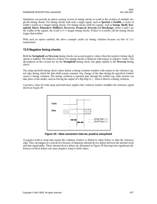
IEEE HARDWARE DESCRIPTION LANGUAGE Std 1364-2001 Simulators can provide an option causing vectors in timing checks to result in the creation of multiple sin-gle-bit timing checks. For timing checks with only a single signal, such as $period or $width, a vector of width N results in N unique timing checks. For timing checks with two signals, such as $setup, $hold, $set-uphold, $skew, $timeskew, $fullskew, $recovery, $removal, $recrem and $nochange, where M and N are the widths of the signals, the result is M*N unique timing checks. If there is a notifier, all the timing checks trigger that notifier.With such an option enabled, the above example yields six timing violation because six bits of DAT transitioned.15.8 Negative timing checksBoth the $setuphold and $recrem timing checks can accept negative values when the negative timing check option is enabled. The behavior of these two timing checks is identical with respect to negative values. The descriptions in this section are for the $setuphold timing check, but apply equally to the $recrem timing check.The setup and hold timing check values define a timing violation window with respect to the reference sig-nal edge during which the data shall remain constant. Any change of the data during the specified window causes a timing violation. The timing violation is reported and, through the notifier reg, other actions can take place in the model, such as forcing the output of a flip-flop to X when it detects a timing violation.A positive value for both setup and hold times implies this violation window straddles the reference signal shown in Figure 49.Figure 49—Data constraint interval, positive setup/holdA negative hold or setup time means the violation window is shifted to either before or after the reference edge. This can happen in a real device because of disparate internal device delays between the internal clock and data signal paths. These internal device delays are illustrated in Figure 50 showing how significant dif-ferences in these delays can cause negative setup or hold values.IEEEStd 1364-2001IEEE ST ANDARD VERILOG®Figure 50—Data constraint interval, negative setup/hold。
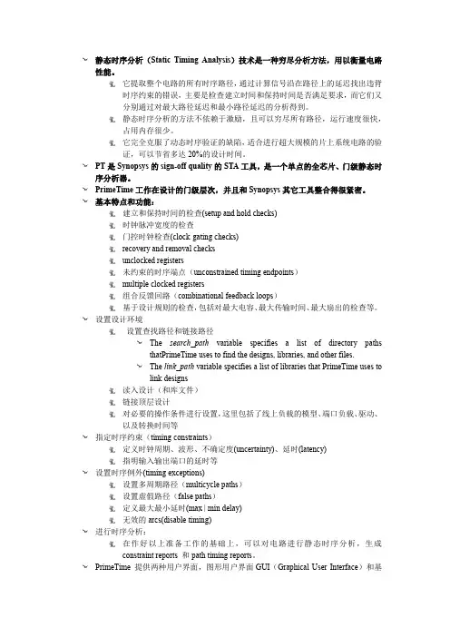
静态时序分析(Static Timing Analysis)技术是一种穷尽分析方法,用以衡量电路性能。
它提取整个电路的所有时序路径,通过计算信号沿在路径上的延迟找出违背时序约束的错误,主要是检查建立时间和保持时间是否满足要求,而它们又分别通过对最大路径延迟和最小路径延迟的分析得到。
静态时序分析的方法不依赖于激励,且可以穷尽所有路径,运行速度很快,占用内存很少。
它完全克服了动态时序验证的缺陷,适合进行超大规模的片上系统电路的验证,可以节省多达20%的设计时间。
PT是Synopsys的sign-off quality的STA工具,是一个单点的全芯片、门级静态时序分析器。
PrimeTime工作在设计的门级层次,并且和Synopsys其它工具整合得很紧密。
基本特点和功能:建立和保持时间的检查(setup and hold checks)时钟脉冲宽度的检查门控时钟检查(clock-gating checks)recovery and removal checksunclocked registers未约束的时序端点(unconstrained timing endpoints)multiple clocked registers组合反馈回路(combinational feedback loops)基于设计规则的检查,包括对最大电容、最大传输时间、最大扇出的检查等。
设置设计环境设置查找路径和链接路径The search_path variable specifies a list of directory pathsthatPrimeTime uses to find the designs, libraries, and other files.The link_path variable specifies a list of libraries that PrimeTime uses tolink designs读入设计(和库文件)链接顶层设计对必要的操作条件进行设置,这里包括了线上负载的模型、端口负载、驱动、以及转换时间等指定时序约束(timing constraints)定义时钟周期、波形、不确定度(uncertainty)、延时(latency)指明输入输出端口的延时等设置时序例外(timing exceptions)设置多周期路径(multicycle paths)设置虚假路径(false paths)定义最大最小延时(max | min delay)无效的arcs(disable timing)进行时序分析:在作好以上准备工作的基础上,可以对电路进行静态时序分析,生成constraint reports 和path timing reports。
多源信息融合英语Multisource information fusion, also known as multisensor data fusion, is the process of combining dataor information from multiple sources in order to create a more complete and accurate understanding of a givensituation or phenomenon. In the context of intelligence analysis, for example, this may involve integrating data from various surveillance systems, human intelligence sources, and open-source information to develop a comprehensive picture of a particular event or threat.From a technical perspective, multisource information fusion often involves the use of algorithms and statistical techniques to merge and analyze data from disparate sources. This can include sensor data from different modalities (such as radar, lidar, and visual cameras), textual information from news reports or social media, and other forms of structured or unstructured data.The benefits of multisource information fusion arenumerous. By integrating data from multiple sources, analysts can reduce uncertainty and improve the overall reliability of their assessments. Additionally, the combination of different types of data can provide insights that would not be possible from any single source alone. For example, combining satellite imagery with ground-based sensor data can enable more accurate geospatial analysis.However, there are also challenges associated with multisource information fusion. These include the need to account for variations in data quality, timing, and relevance, as well as the potential for conflicts or inconsistencies between different sources. Developing effective fusion algorithms and methodologies requires careful consideration of these factors.In summary, multisource information fusion is acritical process in fields such as intelligence analysis, remote sensing, and situational awareness. By integrating data from diverse sources, it enables analysts to gain a more comprehensive and accurate understanding of complexphenomena. This, in turn, supports better decision-making and problem-solving in a wide range of applications.。
时序约束与分析练习:文件夹Timing内为一个已经完成的设计,设计框图见下页。
整个电路有两路数据输入din_a* din_b*和din_x* din_y*;一路来自PCB上100Mhz晶振产生的时钟输入clk_in_100mhz;一路异步复位信号reset;两路数据输出multout_ab multout_xy和一路时钟输出clkout构成中央对齐源同步输出。
电路内所有时钟树由锁相环mail_pll产生,锁相环产生100Mhz输出c100,用于同步电路内所有寄存器;产生200Mhz输出,用于驱动multiplier工作;产生另一个100Mhz输出,用于驱动输出口clkout。
请为该设计添加约束并分析电路是否满足时序要求。
注:时序约束只需告诉QuartusII FPGA片外信号参数,即所有与FPGA相连接的引线。
如所有时钟、所有输入输出端口等。
电路参数:Minimum Maximum Clock-to-output Delay (ns) 1 3Estimated PCB Data Trace0.5 1 Delay (between devices) (ns)Board Clock Skew (ns) -0.5 0.5(0.5 ns)h2操作步骤提示:1、打开Timing目录下top.qpf,Analysis & Synthesis电路,。
2、打开时序分析工具TimeQuest timing analyzer. 。
建立-post_mapNetlist。
3、根据Tasks中unconstrained paths提示,设全所有时钟和外端口约束。
4、建立一个top.sdc文件,对电路的时钟进行约束。
建立基本时钟和衍生时钟。
根据末页电路图,基本时钟名为clk_in_100mhz 100MHZ,锁相环衍生时钟命名为c100/c200/c100_out。
提示:create_clock derive_pll_clock5、从Tasks中看Report Clocks (Tasks pane ⇒Reports⇒Individual Reports).看是否约束了所有时钟。
密级:博士学位论文基于先进ASIC芯片的多探测单元信号读出方法与电路设计作者姓名:杨海波指导教师: 苏弘、研究员、中科院近代物理研究所学位类别: 工学博士学科专业: 核技术及应用研究所: 中科院近代物理研究所二〇一五年五月Signals Reading Method and Circuit Design for Multiple Detection Unit Based on the Advanced ASIC ChipsByYang HaiboA Dissertation Submitted toUniversity of Chinese Academy of SciencesIn partial fulfillment of the requirementFor the degree ofDoctor of Science in EngineeringInstitute of Modern Physics, Chinese Academy of SciencesMay, 2015致谢时光一逝永不回,五年,想想很长,过起来却是如此短暂。
回顾在近物所五年的学习生活,有太多的人需要感谢。
首先,谨向我的导师苏弘研究员,致以最衷心的敬意和谢意。
几年的学习生活中,苏老师给过我太多的指导和帮助,心里的感激也非一言半语所能表达。
苏老师敏锐的思维,踏实的做事风格都时时刻刻影响着我。
本论文之所以能够顺利完成,苏老师倾注了大量的心血,从论文的选题、方案设计,到论文定稿都直接得益于苏老师的悉心指导。
这五年以来,苏老师给了我很多有益的教诲,将使我受益终生。
谢谢您,苏老师。
感谢实验室的千奕老师,孔洁老师。
感谢她们对我工作和生活中的帮助,无论是讨论解决思路、方案设计,还是电路的调试、数据分析,还是生活中遇到的问题,都给与了我极大的帮助和无微不至的照顾。
谢谢你们。
感谢次级束物理研究组的陈金达老师,气体探测器组的张秀玲老师,实验物理中心的杜成名师兄,和已经毕业的陈泽师兄。
成龙十二生肖没有票英语作文Jackie Chan is one of the most iconic and beloved action stars in the world. With his incredible martial arts skills, comedic timing, and daring stunts, he has captivated audiences for decades. In 2012, Chan took on a new project that combined his love of Chinese culture and his talent for entertainment – the film "CZ12," also known as "Chinese Zodiac."The film follows the story of JC, a treasure hunter who is hired to recover twelve bronze animal heads that were stolen from the Old Summer Palace in Beijing during the Second Opium War. These bronze heads, representing the animals of the Chinese zodiac, hold immense cultural and historical significance for the Chinese people. JC embarks on a globe-trotting adventure to track down these valuable artifacts, encountering a diverse array of characters and obstacles along the way.One of the most striking aspects of "CZ12" is the way it showcases the rich cultural heritage of China. The film pays homage to the twelve zodiac animals, each of which has its own unique personalityand symbolism. From the cunning Rat to the noble Horse, the twelve animals are brought to life on the screen with stunning visuals and engaging storytelling.However, the film's exploration of the zodiac animals goes beyond mere aesthetics. It delves into the deeper significance of these cultural symbols and their role in shaping Chinese identity and tradition. The film's central premise – the theft and recovery of the bronze heads – serves as a metaphor for the preservation and reclamation of Chinese cultural heritage in the face of colonial exploitation and globalization.Moreover, "CZ12" is not just a action-packed adventure film; it also grapples with themes of identity, belonging, and the pursuit of personal and cultural fulfillment. JC, the protagonist, is a complex character who struggles with his own sense of purpose and connection to his heritage. As he travels the world in search of the bronze heads, he is forced to confront his own sense of displacement and the challenges of navigating multiple cultural identities.One of the most poignant moments in the film comes when JC visits the Old Summer Palace, the site of the original theft of the bronze heads. The palace, now in ruins, serves as a powerful symbol of the country's turbulent history and the ongoing struggle to preserve its cultural legacy. JC's emotional reaction to this site underscores thedeep personal and national significance of the bronze heads, and the film's broader message about the importance of safeguarding and celebrating cultural heritage.Throughout the film, Jackie Chan's masterful performance and the film's stunning visual effects work together to create a truly immersive and engaging cinematic experience. The action sequences, which are a hallmark of Chan's filmography, are particularly impressive, blending breathtaking stunts with a keen sense of choreography and comedic timing.However, despite the film's critical and commercial success, it has also faced some challenges and controversies. One of the most notable issues has been the lack of tickets available for the film's screenings, particularly in certain markets. This has led to a significant amount of frustration and disappointment among fans who have been unable to see the film in theaters.The lack of tickets for "CZ12" is a complex issue that highlights some of the broader challenges facing the film industry, particularly in the context of global distribution and audience demand. On one hand, the high level of interest in the film is a testament to its cultural significance and the enduring popularity of Jackie Chan and his work. However, the limited availability of tickets has also been a source of frustration for many fans, who have felt excluded from the cinematicexperience.One possible explanation for the ticket shortage is the film's distribution model. As a Chinese production with a strong focus on Chinese cultural themes and heritage, "CZ12" may have faced challenges in securing widespread international distribution and marketing. This could have led to a more limited number of screening opportunities in certain markets, particularly those outside of China.Additionally, the film's release coincided with a broader trend of increasing demand for international and culturally-specific content in the global film market. As audiences around the world become more interested in exploring diverse cultural perspectives and narratives, the competition for limited screening opportunities has become more intense.Despite these challenges, the lack of tickets for "CZ12" has also highlighted the importance of accessibility and inclusivity in the film industry. By ensuring that all audiences, regardless of their cultural background or geographic location, have the opportunity to experience and engage with culturally significant films, the industry can help to foster a more diverse and representative cinematic landscape.In conclusion, "CZ12" is a remarkable film that showcases the rich cultural heritage of China and the enduring appeal of Jackie Chan's cinematic artistry. While the lack of tickets for the film's screenings has been a source of frustration for many fans, it also underscores the broader challenges and opportunities facing the film industry in an increasingly globalized and culturally diverse world. By continuing to celebrate and preserve cultural heritage through the medium of film, and by ensuring that these stories are accessible to all audiences, the industry can play a vital role in promoting cross-cultural understanding and appreciation.。
多因素实验设计英文文章Multi-factor Experiment DesignMulti-factor experiment design is a method of designing experiments that involve multiple factors. It is used to study the effect of several variables on a response. This method is used in many different fields, from medicine to engineering.The basic idea behind multi-factor experiment design is to create a set of experiments that vary the levels of each factor. The levels of each factor can be varied independently, or in combination. The goal is to determine how the response is affected by each factor.Multi-factor experiment design can be used to study the effects of a single factor or multiple factors. For example, in a medical study, researchers may want to study the effects of a drug on a particular disease. They could design an experiment where they vary the dosage of the drug, the frequency of administration, and the duration of the treatment.In engineering, multi-factor experiment design is used to study the effects of different design parameters on a product or system. For example, an engineer may want to study the effects of a material's thickness, density, and temperature on the strength of a structure. Multi-factor experiment design is also used in marketing. For example, a company may want to study the effects of different advertising campaigns on sales. They could design an experiment where they vary the type of advertisement, the media used, and the timing of the campaign.Multi-factor experiment design can be used to study the effects of any combination of factors. It is a powerful tool for understanding the relationships between different variables and their effects on a response.。
有难度的技巧英文Challenging Skill Techniques1. Advanced Data Analysis: This skill involves conducting complex statistical analyses, data mining, and using advanced software and programming languages like R or Python to extract meaningful insights from large datasets.2. Multivariable Calculus: Multivariable calculus deals with functions of more than one variable and techniques for studying them, such as partial derivatives, multiple integrals, and vector calculus. Mastering this skill enables a deeper understanding of complex mathematical models and their applications in fields like physics and economics.3. Ethical Hacking: Ethical hacking, also known as penetration testing or white-hat hacking, involves identifying vulnerabilities and weaknesses in computer systems and networks. This skill requires knowledge of various hacking techniques, network protocols, and programming languages like C++ or Python to exploit vulnerabilities safely and secure systems against cyber-attacks.4. Advanced Pilates: Pilates is a system of exercises designed to improvephysical strength, flexibility, and control. Advanced Pilates techniques include mastering complex movements like the flying squirrel, scorpion, or side crow, which require exceptional core strength, balance, and coordination.5. Fluent Public Speaking: Public speaking is a valuable skill, but becoming fluent in it takes practice and refinement. This includes techniques such as mastering persuasive language, effective body language, managing nerves, and engaging with different types of audiences.6. Advanced Chess Strategies: Chess is a game of strategy and tactics, and advanced techniques involve understanding various strategies such as positional play, sacrifices, endgame theory, and deep calculations. These skills enable players to anticipate and plan several moves ahead, making it challenging to master.7. High-Level Musical Instrument Proficiency: Mastering a musical instrument at a high level involves honing technique, sight-reading, improvisation skills, and understanding advanced musical theory and concepts. Achieving mastery often requires years of dedicated practice and study.8. Advanced Yoga Poses: Yoga comprises a range of postures, and advanced techniques involve achieving challenging poses like scorpion, handstand, or one-armed peacock. These advanced poses require exceptional balance, strength, and flexibility, making them difficult to master.9. Expert-level Programming: Becoming an expert programmer involves mastering multiple programming languages, algorithms, data structures, and software development methodologies. Advanced programming skills are essential for building complex software systems and solving intricate technical problems efficiently.10. Professional Level Cooking Techniques: Professional chefs employ advanced cooking techniques like molecular gastronomy, sous vide, or intricate knife skills to elevate their culinary creations. These skills require precise timing, attention to detail, and a deep understanding of ingredients and flavors.。
Timing Analysis:In Search of Multiple ParadigmsFrank MuellerDepartment of Computer Science/Center for Embedded Systems ResearchNorth Carolina State University448EGRC,Raleigh,NC27695-7534e-mail:mueller@,phone:+1.919.515.7889,fax:+1.919.515.7925AbstractWhile timing analysis is a vital prerequisite for real-time schedulability tests,prior advances on timing analysis were sometimes incremental in addressing selected new proces-sor features or limited source code annotations to provide safe but tight WCET bounds.In contrast,recent advances in timing analysis including a refreshing set of novel ap-proaches to bound the worst-case execution time(WCET) of real-time tasks.These advances are in search of new methodologies to address the timing analysis problem and approach this problem in a more general manner.Examples are1)the complexity wall of hardware that causes timing analysis tools to trail behind the curve of microarchitectural innovation,2)severe restrictions on the knowledge of loop bounds,3)the inability to analysis large application pro-grams,4)a lack of capitalizing on opportunities of dynamic scheduler interactions and5)the challenge in expressing certainty levels of WCET bounds.This paper gives an overview of selected approaches and contributes an initial account on the potential of the con-tributions for thefield.Each of these novel approaches to timing analysis solves one problem in current toolsets.It appears that the diversity of approaches is a valuable asset to the research area.While a particular solution may prove best suitable for some problem,another approach may be required for different problems.Furthermore,many of the recent advances are complementing each other.Some can be used in conjunction to provide additional robustness to hard real-time systems.1.IntroductionSchedulability analysis of real-time systems determines if given a set of tasks can be feasibly scheduled such that every deadline is met.The specification of task sets in-cludes,at a minimum,the period and the worst-cases ex-ecution time(WCET)of each task.While the period is typically derived from the application environment,deter-mining the WCET remains a hard problem,particularly for complex application codes with large inputs and advanced architectures with sources of unpredictable behavior.The objective of timing analysis is to provide upper bounds on the worst-case execution time(WCET)of hard real-time tasks.By designing timing analysis tools to safely and tightly predict the WCET,much of the challenge of timing analysis can be addressed in an automated fashion. Nonetheless,timing analysis has,to date,only been applied to small codes and simple architectures.Manual annota-tions are often required to supplement source code with constraints necessary to bound selected loop iterations and describeflow dependencies in order to derive tight WCET rger programs or programs with complex inputs typically exceed the capability of analysis tools due to non-linear analysis overheads.Advances in microarchitecture create a complexity wall,which causes timing analysis tools to generally trail years behind the curve of architectural in-novations.To address these problems in timing analysis,recent re-search has taken fresh approaches at the problem.Archi-tectural enhancements have been proposed to counter the complexity wall in processor innovations.Methods of para-metric timing analysis have been explored to handle loops with variable bounds and provide late bindings for the ac-tual number of loop iterations.Modular analysis methods have been proposed to address the analysis constraints on large programs.Instead of requiring tight WCET bounds, looser bounds are deemed sufficient for dynamic voltage scaling(DVS)scheduling algorithms that trade speed for power conservation.Frequency-aware static timing analy-sis(FAST)complements DVS scheduling for real-time sys-tems by ensuring the timing predictions do not deteriorate to a level where power consumption is sacrificed because of inaccuracies in bounding the WCET.While static timing analysis approaches can be complemented by experimen-tal timing values,e.g.,through genetic algorithms to search for longer execution times as a function of the input,recent work is promoting extreme statistics in conjunction with ob-served timing measurements in a probabilistic WCET as-sessment.Resulting WCET bounds are guaranteed with a certainty of some probability.In the following,an overview of some of these novel ap-proaches is given.Some of these research advances solve one problem in current timing analysis toolsets.The diver-sity of approaches provides a valuable asset to the research area in large.While a particular solution may prove best suitable for some problem,another approach may be re-quired for different problems.Furthermore,many of the recent advances are complementing each other.For exam-ple,DVS scheduling and FAST can be used in conjunction to provide additional robustness to hard real-time systems.2.VISA:A Virtual Simple ArchitectureVISA resolves a long-standing problem in embedded systems:bounding the worst-case execution times(WCET) of tasks on contemporary processors.WCETs are essential for real-time scheduling;yet deriving them for contempo-rary processors is intractable.The Virtual Simple Archi-tecture(VISA)framework shifts the burden of bounding the WCETs of tasks,in part,to hardware.A VISA is the pipeline timing specification of a hypothetical simple pro-cessor.WCET is derived for a task assuming the VISA. At run-time,the task is executed speculatively on an unsafe complex processor,and its progress is continuously gauged. If continued safe progress appears to be in jeopardy,the complex processor is reconfigured to a simple mode of operation that directly implements the VISA,thereby ex-plicitly bounding the task’s overall execution time by the WCET.System design involves defining a VISA,and then im-plementing a static timing analyzer and a complex proces-sor,the latter two compliant with the VISA.In defining the VISA,we considered the capabilities of current timing anal-ysis tools.We also considered how a simple mode of opera-tion is likely to be accommodated within a typical dynami-cally scheduled superscalar processor and,in particular,the complex processor described in[1].The three layers—VISA,processor,and timing analyzer—are shown in Fig.1 and are described in detail elsewhere[1].Typically,the VISA-protected complex processorfin-ishes periodic hard-real-time tasks faster than an explicitly-safe simple processor,creating slack in the schedule.Dy-namic slack cannot be used to schedule more periodic hard-real-time tasks,because WCETs are based on the hypothet-ical simple processor.Nonetheless,slack can be exploited to safely lower frequency/voltage for power savings.This application was explored in our recent ISCA’03paper[1],Figure1.VISA Abstraction Layerswhich demonstrated43-61%power savings.In summary,VISA provides a general framework for safe operation on unsafe processors,setting up new oppor-tunities for exploiting higher performance in embedded sys-tems.3.Parametric Timing AnalysisTraditionally,static timing analysis yields a discrete pre-diction of the WCET based onfixed iteration bounds that have to be known statically.Such analysis requires that the actual number of iterations always be known prior to exe-cution of a real-time task.This work addresses these limitations of timing analy-sis for embedded systems.It contributes a novel approach to program analysis through parametric techniques of static timing analysis and provides innovative methods for ex-ploiting them.The proposed techniques express worst-case execution time as a formula with the following benefits. First,static timing analysis becomes applicable to a wide class of embedded systems with variable loop bounds.Sec-ond,the techniques of static timing analysis,currently con-strained to hard real-time system,become applicable to a much wider range of embedded systems with soft timing constraints.For example,a loop may encompass iterations,where depends on the current input.Typically,the number of it-erations is already known prior to entering the loop.Static timing analysis may supply a closed formula to predict the WCET for the remaining execution time based on dynamic information,such as the actual value of.A novelfix-point algorithm has been developed to derive closed formulas for expressing the WCET bounds on loops with variable trip counts.Preliminary experimental results using parametric analysis in contrast to the traditional nu-merical technique illustrate the feasibility this novel ap-proach[7].Parametric timing analysis only looses an in-significant amount of precision(tightness)in bounding theWCET.The benefit offlexibility outweights this diminish-ing cost.Applications of the approach lie in novel applica-tions for dynamic scheduling decisions and a potential for more effective system utilization.4.Modular Static Cache SimulationStatic timing analysis techniques derive safe WCET bounds via path analysis,pipeline simulation and cache simulation.But such analysis has traditionally been con-strained to only small programs due to the complexity of simulation,most notably by static cache simulation,which requires inter-procedural analysis.A novel approach of modular static cache simulation is devised that alleviates the complexity problem,thereby making static timing analysis feasible for much larger programs that in the past.The main contribution of this effort is a framework to perform static cache analysis in two steps,a module-level analysis and a compositional phase,thus addressing the is-sue of complexity of inter-procedural analysis for an entire program.The module-level analysis parameterizes the data-flow information in terms of the starting offset of a module. The compositional analysis stage uses this parameterized data-flow information for each module.Thus,the emphasis here is on handling most of the complexity in the module-level analysis and performing as little analysis as possible at the compositional level.The experimental results for direct-mapped instruction caches show that the composi-tional analysis framework provides equally accurate predic-tions when compared with the simulation approach that uses complete inter-procedural analysis[5].This novel approach to static cache analysis provides a promising solution to the complexity problem in timing analysis,which,for thefirst time,makes the analysis of larger programs feasible.5.DVS:Dynamic Voltage SchedulingDynamic voltage scaling(DVS)is a promising method for embedded systems to exploit multiple voltage and fre-quency levels and to prolong battery life.Numerous DVS scheduling algorithms for real-time systems have been pro-posed,but the most promising approaches are those that capitalize slack reclamation due to idle time(static slack) and,in addition,slack due to early completion(dynamic slack).This requires a dynamic scheduling scheme,such as EDF enhanced by slack reclamation and voltage/frequency modulation,e.g.,Look-ahead EDF[6].The benefit for DVS scheduling for real-time systems is that even loose WCET bounds suffice since voltage/frequency modulation is based on the actually observed execution times in dy-namic scheduling schemes.Notice that static DVS schemes cannot be as aggressive and,hence,should receive less attention.Furthermore,DVS scheduling can,in general, profit from deviations between WCET and actual execution times,which are reportedly significant with the actual ex-ecution time of real-time tasks ranging from about30%to 90%of the WCET,depending on the application.Pure DVS techniques do not perform well for dynamic systems where the system workloads vary significantly.A novel approach combining feedback control with DVS schemes was devised targeting hard real-time systems of dynamic workloads.This method relies strictly on oper-ating system support by integrating a DVS scheduler and a feedback controller within the EDF scheduling algorithm. The scheme splits each task into two portions,and aims at finishing the actual execution within thefirst portion of each task while reserving enough time in the second portion to meet the deadline following a last-chance approach.Feed-back techniques make the system capable to select the right frequency and voltage settings for thefirst potion,as well as guaranteeing the deadline requirements of the hard real-time task sets.Simulation experiments demonstrate that our algorithm is able to saves up to29%more energy than pre-vious work for task sets with different dynamic workload characteristics[10,3,9].6.FAST:Frequency-Aware Static TimingAnalysisDVS techniques for real-time scheduling focus on saving power in static as well as dynamic scheduling environments by exploiting idle and slack due to early task completion for DVS of subsequent tasks.As mentioned before,these ap-proaches rely on a priori knowledge of the WCET for each task.All DVS scheduling algorithms assume that DVS has no effect on the worst-case execution cycles(WCEC)of a task and scale the WCET according to the processor fre-quency.However,for systems with memory hierarchies, the WCEC typically does change under DVS due to fre-quency modulation.Hence,current assumptions used by DVS schemes result in a highly exaggerated WCET.A novel technique for tight andflexible static timing analysis is developed that is particularly well-suited for dy-namic scheduling schemes.The technical contributions are as follows:(1)The problem of changing execution cycles due to scaling techniques is assessed.(2)A parametric ap-proach towards bounding the WCET statically with respect to the frequency is ing a parametric model, one can capture the effect of changes in frequency on the WCEC and,thus,accurately model the WCET over any frequency range.(3)Design and implementation of the frequency-aware static timing analysis(FAST)tool are dis-cussed based on prior experience with static timing analy-sis.(4)Experiments demonstrate that the FAST tool pro-vides safe upper bounds on the WCET,which are tight.The tool provides the means to capture the WCET of six benchmarks using equations that overestimate the WCET by less than1%.FAST equations can also be used to im-prove existing DVS scheduling schemes to ensure that the effect of frequency scaling on WCET is considered and that the WCET used is not exaggerated.(5)Three DVS schedul-ing schemes are leveraged by incorporating FAST into them and by showing that the power consumption further de-creases.Overall,FAST and DVS scheduling techniques for real-time systems provide a symbiotic solution to aggres-sive lower power consumption without missing deadlines–and to cope with(as well as benefit from)looser WCET bounds.7.Probabilistic Timing AnalysisTraditional timing analysis techniques rely on static analysis of programs.Past work has discussed the bene-fits of complementing static and dynamic analyses for soft and hard real-time systems,most notably by guiding the search for the WCET in dynamic analysis via genetic al-gorithms[4,8].Taking dynamic analysis one step further, recent work promotes a probabilistic approach to provide certainty levels for the WCET.These certainty levels,ex-pressed as probabilities,are based on a sample of observed executions and combined with extreme-value statistics.The supporting experimentation tool,the pWCET tool,handles timing at a basic block level and combines analysis with the traditional timing schema[2].Such an approach can also be combined with the VISA architecture to obtain WCET bounds for the simple mode.VISA then provides safety by gaging progress in complex mode since non of the above static analysis techniques can fully capture the effects of a complex architecture.Even the pWCET results at some cer-tainty level can profit from the additional safety provided by VISA.8.ConclusionThis paper provided an overview of a variety of se-lected novel approaches in tackling the problem of provid-ing bounds for the WCET of real-time tasks.These research advances each solve some problem in current timing anal-ysis toolsets.The diversity of approaches provides a valu-able asset to the research area in large.While a particular solution may prove best suitable for some problem,another approach may be required for different problems.Further-more,many of the recent advances are complementing each other.For example,DVS scheduling and FAST as well as VISA and pWCET can be used in conjunction to provide additional robustness to hard real-time systems.Overall,the field of timing analysis has matured and,at the same time,is still open to new discoveries with potentially significant impact.References[1] A.Anantaraman,K.Seth,K.Patil, E.Rotenberg,andF.Mueller.Virtual simple architecture(VISA):Exceedingthe complexity limit in safe real-time systems.In Inter-national Symposium on Computer Architecture,pages250–261,June2003.[2]G.Bernat,A.Collin,and S.Petters.Wcet analysis of prob-abilistic hard real-time systems.In IEEE Real-Time Systems Symposium,Dec.2003.[3] A.Dudani,F.Mueller,and Y.Zhu.Energy-conservingfeedback edf scheduling for embedded systems with real-time constraints.In ACM SIGPLAN Joint Conference Languages,Compilers,and Tools for Embedded Systems (LCTES’02)and Software and Compilers for Embedded Systems(SCOPES’02),pages213–222,June2002.[4] F.Mueller and J.Wegener.A comparison of static analysisand evolutionary testing for the verification of timing con-straints.In IEEE Real-Time Technology and Applications Symposium,pages179–188,June1998.[5]positional static cache analysis using module-level abstraction.Master’s thesis,Dept.of CS,North Car-olina State University,Aug.2003.[6]P.Pillai and K.Shin.Real-time dynamic voltage scaling forlow-power embedded operating systems.In Symposium on Operating Systems Principles,2001.[7] E.Vivancos,C.Healy,F.Mueller,and D.Whalley.Paramet-ric timing analysis.In ACM SIGPLAN Workshop on Lan-guage,Compiler,and Tool Support for Embedded Systems, volume36of ACM SIGPLAN Notices,pages88–93,Aug.2001.[8]J.Wegener and F.Mueller.A comparison of static analysisand evolutionary testing for the verification of timing con-straints.Real-Time Systems,21(3):241–268,Nov.2001. [9]Y.Zhu and F.Mueller.Preemption handling and scalabilityof feedback dvs-edf.In Workshop on Compilers and Oper-ating Systems for Low Power,Sept.2002.[10]Y.Zhu and F.Mueller.Feedback dynamic voltage scalingdvs-edf scheduling:Correctness and pid-feedback.Techni-cal Report TR2003-13,Dept.of Computer Science,North Carolina State University,2003.。