BE-2625姿态测量模块使用手册V1.0
- 格式:pdf
- 大小:262.78 KB
- 文档页数:3

"博大5" 装载仪操作手册"BODA5"USER M ENU上海亮格船舶工程技术有限公司SHANGHAI LIANGGE SHIPS E NGINE E RING TE CHNIQUE CO.,LTD.2012/11/18目录1I n t r odu ct ion(简介) (4)2Test Con dit ion(测试工况说明) (4)3I n st allat ion(安装) (5)4St ar t in g Pr ogr am(启动) (6)5F ile(文件) (9)5.1N ew(新建工况) (9)5.2Sa ve(保存工况) (9)5.3Sa ve a s(工况另存为) (10)5.4Open(打开工况) (10)5.5Open St a n da r d(打开标准工况) (11)5.6Pr in t(打印) (11)5.7Pr in t pr eview(打印预览) (11)5.8Pr in t set(打印设置) (11)5.9Pa sswor d(密码) (11)5.10C h a n ge pa sswor d(密码更改) (12)5.11Exit(退出) (12)6Ar r an gemen t(分类) (12)6.1Voya ge in for ma t ion(航次信息) (12)6.2C on st a n t(船员和常数) (13)6.3C a r goes loa d(货舱货) (13)6.4Ta n k s loa d(压载水等液舱) (14)6.5B a les(大件货) (15)7Con t ain er(集装箱) (16)7.1B a yPla n (16)7.2C u r r en t ba y(当前B a y) (20)7.3All ba y(所有B a y) (21)7.4Set t in g Loa din g Por t(设置挂港代码) (21)7.5Set defa u lt box(设置默认箱) (22)7.6Empt y box weigh t(空箱设置) (22)7.7Rea d ED I file(读Edi文件) (22)8E valu at ion(计算) (25)8.1Su mma r y(总表) (25)8.2St a bilit y(稳性计算) (25)8.3St r en gt h(强度计算) (26)8.4D r a ft Su r vey(六面水尺测量) (27)8.5H ydr o da t a(静水力数据) (28)9Repor t(报告) (28)9.1Repor t(报告) (28)9.2B a yPla n(B a ypla n总图) (29)9.3B a yPla n of a ba y(B a ypla n单图) (30)9.4B a y list(按B a y重量列表) (30)10Opt ion s(选项) (31)10.1Ala r m(声响报警) (31)10.2Specific Gr a vit y(比重设置) (31)10.3Fr om AP(距艉) (31)11H elp(帮助) (31)11.1H elp(帮助) (31)11.2Abou t(关于) (32)11.3Regist er(注册) (32)12E xample(例子) (32)12.1N ew(新建) (32)12.2Voya ge in for ma t ion( 航次信息) (34)12.3C r ew & C on st a n t(船员和常数) (35)12.4C a r goes H old(货舱装载) (35)12.5Ta n k s Loa din g(液舱装载) (35)12.6C on t a in er(集装箱装载) (36)12.7C h eck Resu lt(检查结果) (39)13Appen dix(附录) (41)13.1St owa ge fa ct or(积载因数换算表) (41)13.2con figu r a t ion(配置) (41)13.3Soft wa r e mist a k e(错误应对) (41)13.4Wa r n in g(警告) (42)13.5OPERATION AL RESTRIC TED D ATA(操作限制资料) (42)1Introduction(简介)1.About software(软件概况)FUHAI Loading Program is a software system for ship loading calculation on-board in real time. It has friendly user interface. Using this system, user can load container quickly or input tanks data easily. The stability can be calculated and the distribution of shear force and bending moment of the ship under the loading condition can be obtained.福海船舶装载仪是一个船舶运行的装载计算软件,具有友好的操作界面,能快捷地输入集装箱数据和液舱重量数据,并能迅速地计算出船舶浮态和稳性,以及船舶的剪力弯矩分布状况。

Specifications subject to change without notice. Copyright © 2009 Extech Instruments Corporation. All rights reserved including the right of reproduction in whole or in part in any form.6/26/09 - R1Multifunctional MeterMeasures Acceleration, Velocity and Displacement plus RPM and Linear Surface Speed.Vibration Meter + Laser Combination T achometerOrdering Information:461880....................Vibration Tachometer461880-NIST ..........461880 with NIST CertificateFeatures:•Unique large LCD with characters on display reverse direction depending on contact, photo, or vibration mode•Windows ®95/98/NT/2000/XP compatible software (included)allows captured readings to be downloaded to your PC for further analysis•Complete with remote vibration sensor, magnetic mount, wheels for linear surface speed or RPM (cone tip and flat tip), reflective tape, 4 AA batteries, software with cable, and hard carrying caseVibration Meter Features:•Remote vibration sensor with magnetic adapter on 39"(1m) cable •Wide frequency range of 10Hz to 1kHz •RMS or Peak Value measurement modes •Manual/Auto store/recall up to 1000 readings •Data Hold freezes the reading in the display •Auto shut-off saves battery lifeTachometer Features:•Uses a laser for greater distance non-contact measurements up to 4.9ft (1.5m)•Stores last, max, and min readingsContact Tachometer function measures the speed of rotating objects by placing the wheel tip onto the surface.Photo Tachometer function measures the speed of rotating objects without contacting the surface by using a laser beam SpecificationsVibration Meter A cceleration656ft/s 2, 200m/s 2, 20.39g Velocity7.87in/s, 200mm/s, 19.99cm/s Displacement 0.078in, 2mmResolution 1ft/s 2, 0.1m/s 2, 0.01g; 0.01in/s, 0.1mm/s, 0.01cm/s; 0.001in, 0.001mm Basic accuracy ±(5%+2 digits)Tachometer Photo 10 to 99,999rpm Contact0.5 to 19,999rpmSurface Speed 0.2 to 6,560ft/min (0.05 to 1,999.9m/min)Basic accuracy ±(0.05%+1 digit)Dimensions 7.4 x 3 x 1.8" (188 x 75.5 x 46.8mm)Weight1.12lbs (507g)。

面风压计8710中文说明书第1章介绍面风压计8710是一台重量轻且易操作的仪器,搭配各种附件可测量压力,温度,湿度,空气风速,和空气流量。
风量罩包括下列特色:单功能键操作方便压力测量自动调零和自动密度修正使用者可选择英制和公制单位实际和标准流量之间转换分离或连续的显示和资料记录功能输出端口可下载到打印机或电脑由交流转换器或电池(镍氢充电电池或碱性电池)供电现场测试校正风量罩适用人群:专业人员的测试和平衡机械承包商工业卫生学者工厂工程师和设备保养人员应用包括:测试,平衡,或订制HVAC系统测试无尘室和生物安全柜测量排烟柜或过滤器表面风速测量压力,温度,相对湿度,空气风速,或空气流量仪器介绍基本的面风压计8710型包括主机,携行袋,18英寸长(46公分)皮托管,(2)静压探针,(2)8英尺长(2.4公尺)Norprene管,使用说明书,LogDat TM 资料下载软件和RS-232接口电缆线,挂绳,内置镍氢电池充电器,(4)AA型镍氢电池,交流转换器,NIST校准证书。
TSI面风压计8710型风量罩增加了一个2英尺×2英尺(610毫米×610毫米)的风量罩,底座和有轮携行袋。
多种选用的器械(如下)可符合你的测量需要。
下面的段落简单的叙述了风量罩和供风量罩使用的各种标准的和选用的器械;关于风量罩和各种感应器和探针的测量更详细的叙述请参阅第3和4章。
风量罩图1和2给出风量罩的特色。
图1:面风压计8710型DP-Calc 风量罩的特色,前视图2:面风压计8710型DP-Calc 风量罩的特色,背视风量罩风量罩是一台多功能仪器,当与下面列表的器械一起使用时可以得到空气风速,空气流量,绝对和相对压力,温度,和湿度。
轻便的风量罩能为高精度,低流量测量自动调零。
标准器械此节简单的描述了风量罩的标准器械皮托管皮托管主要是用于风管内的空气风速,空气流量,和风速压力的测量。
静压探针静压探针主要用于风管静压力的测量。

107409901 BOperating instructionsAERO 26AERO 31 INOXOperating instructions ....................................................................................................1Bedienungsanweisungen ...............................................................................................8Instructions de fonctionnement ...................................................................................15Gebruiksaanwijzingen ...................................................................................................22Istruzioni per l’uso .........................................................................................................29Bruksanvisning ..............................................................................................................36Bruksanvisning ..............................................................................................................43Betjeningsvejledning ....................................................................................................50Käyttöohje . (57)Instruccciones de funcionamiento ..............................................................................64Instruções de Funcionamento .....................................................................................71Οδηγίες λειτουργίες ......................................................................................................78Kullanma Talimatlar ı ......................................................................................................86Navodila za delovanje ...................................................................................................93Upute za uporabu ........................................................................................................100Návod na obsluhu .......................................................................................................107Návod k obsluze ...........................................................................................................114Instrukcje dotycz ące obs ługi .....................................................................................121Használati útmutató ....................................................................................................128Instruc ţiuni de utilizare (135)Указания за експлоатация ........................................................................................142Руководство по эксплуатации .................................................................................149Tööjuhised ...................................................................................................................157Nor ād ījumi par ekspluat āciju ......................................................................................164Naudojimo instrukcija .................................................................................................171 .............................................................................................................................178操作说明 .........................................................................................................................185사용법.............................................................................................................................191คําแนะนําการใช้งาน .......................................................................................................197Arahan Operasi . (203)ﺕﻉﻝﻱﻡﺍﺕ ﺍﻝﺕﺵﻍﻱﻝ (210)ARAERO 26-01 X AERO 26-21AERO 31-21 INOX AERO 26-2L2A4B*)5B*)2D快速参考指南图解快速参考指南该图解快速参考指南旨在协助您启动、操作和存放该启动前1A - 取出附件2A - 安装过滤袋控制/操作1B - 清空容器2B - 鼓风功能3B - 推入 & 清洁连接电气设备1D - 过滤袋更换2D - 过滤器更换*) 可选附件 / 选件依机型而定目录1 重要安全说明 (186)1.1 说明中的标志 (186)1.2 使用说明 (186)1.3 目的与指定用途 (186)1.4 电气连接 (186)1.5 延长导线 (186)1.6 质保 (186)1.7 测试与批准 (186)1.8 重要警告 (186)1.9 双重绝缘设备* (187)2 风险 (187)2.1 电气部件 (187)2.2 抽吸液体物 (187)2.3 危险材料 (187)2.4 零件及附件 (187)2.5 清空污物箱 (188)2.6 易爆或易燃环境下 (188)2.7 鼓风功能。
ORG447X Evaluation Kit Quick Start Guide1.P a c k a g i n g L i s tThe ORG447X Evaluation Kit contains:4472 module mounted on the Demo BoardB.Passive patch antenna assemblyB to UART cableD.Support CD2.S e t u p2.1 Open CD. Select ORG447X series from the main menu.2.2 Install FTDI USB-UART driver by pressing Driver button.The driver setup is done in silent mode.The presence and enumeration of the Virtual COM port can be verified via ControlPanel→System→Device Manager.2.3 Install SiRFLive software by pressing SiRF Live Setup button.Follow on-screen instructions during SiRFLive setup process.Uninstall any previous SiRFLive version before current setup attempt.2.4 Connect antenna assembly cable into RF input connector.2.5 Connect FTDI USB to UART cable between the Demo Board and the PC.3.E v a l u a t i o n K i t E s s e n t i a l s3.1 Patch antennaGPS patch antenna should be placed up towards the sky to keep GPS satellites in view. 3.2 Tactile switchThe tactile switch is used to wake up to GPS module from the Hibernate state of one of the low power modes, typically for triggering Push-To-Fix (PTF™).4.S i R F L i v e E s s e n t i a l s4.1 Linking with EVKA. Open SiRFLive by clicking desktop iconB. Press Receiver Settings button on the main toolbarC. Rx Port Settings window will openSelect GSD4e in Product Family box.Select RS232/USB for Physical Connection.Select the Virtual COM port as assigned by the driver. Typically it would be the highestavailable.Select 4800 for Baud Rate.Press OK button when finished.D. Press Connect button on the main toolbarThe NMEA messages will start bursting in Debug View window.4.2 Switching ProtocolsExtended functions like TTFF measurement are available after switching the receiver into OSP binary protocol.A. Goto Receiver → Command → Switch ProtocolsB. Switch Protocols window will openClick Set button to transfer the EVK into OSP binary protocol @ 115,200 bps.4.3 The TTFF MeasurementsA. Press TTFF button of the main toolbarB. TTFF/Nav Accuracy window will openC. Click the Setup Reference Location button (for accuracy measurements)D. Set Reference Location window will openSelect USER_DEFINED under Reference Location.Input location name.Press Fix Pos button to use current position coordinate.Press Set as Default button to use current location for position reference.Press OK button when finished.E. Press Reset button on the main toolbar.F. Reset window will openSelect Reset Mode.Reset Modes are:Hot Start - Ephemeris, Almanac, clock and last position data are kept in receiver’s RAM.Warm Start (No Init) – Ephemeris and last position data are discarded.Warm Start (Init) - Ephemeris data is discarded, position data is loaded.Cold Start – All data except reference Almanac is discarded.Factory Reset – All data, including reference Almanac and power settings is discarded.Factory (Clear XO learning) – Not relevantFactory (Keep Flash/Eeprom data) – Not relevantCheck Enable Navlib Data box and Enable Development Data box.Press Send button to start the procedure.The EVK will perform reset sequence.G. TTFF/Nav Accuracy window will show TTFF measurements data4.4 Sequential TTFF Measurements - LOOPIT functionA. Goto Receiver → Automation Test → LoopitB. Information pop-up window will openPress Yes button to continue.C. Loopit window will openSelect the Reset TypeSet the number of iterations.Checking Allow Early Iteration Completion box is an option to allow the next reset to be sent immediately after the previous cycle finish.Leave Switch Protocol/Baud on Factory and Perform Aiding on Factory unchecked.Press Start button to commence the procedure.D. Log file pop-up window will openPress Yes button to continue.H. TTFF/Nav Accuracy window will show sequential TTFF measurements data4.5 Data LoggingA. Press Log File button on the main toolbarB. Log File window will openPrior to logging set the receiver to appropriate data protocol.For NMEA messages log select TXT format in Log Format combo box.The log file will be created with .TXT extension.For OSP binary messages log select GPS format in Log Format combo box.The log file will be created with .GPS extension.Press Start button to commence logging.Press Log File button while logging to stop the procedure.ORG447X Series Evaluation Kit Quick Start Guide Fully Integrated GPS ModuleDocument number: 120111 Fortechnicalquestions,contact:****************** Revision: A01 15-11-1111 4.6 Data PlaybackA. Press Play File button on the main toolbarB.File browser will openSelect saved file.C.File Playback Warning pop-up will openPress Yes button to continue.D. Navigate through recorded file with toolbar controlsE. View windows are selected via main toolbarFor extended support for SiRFLive software refer to the SiRF Live Manual on this CD.。
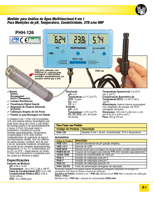
B-1e B ateria Interna Recarregável (Inclui Carregador)e Leituras Simultânease Visualização Digital Grandee Adaptador de Corrente Alternada (Incluído)e Calibração Simples de Um Pontoe Portátil ou para Montagem em ParedeO medidor 6 em 1 PHH-126 foi projetado com uma bateria interna recarregável que pode durar cerca de 3 anos e cujo tempo de recarga padrão é de aproximadamente 2 horas. O PHH-126 pode medir 4 parâmetros, incluindo pH (sonda vendida separadamente), temperatura, condutividade e STD. Este monitor multiparâmetros de qualidade da água é um instrumento versátil, com um sistema de várias sondas, confiável, fácil de usar e de ler. Apresenta medições simultâneas de sonda de pH (vendida separadamente), temperatura (°C ou °F), condutividade (EC ou CF) ou STD – basta apertar um botão. O PHH-126 é econômico e projetado para ser usado por técnicos e leigos.Especificações Intervalo de Medição p H: 0,00 a 14,00 Temperatura: -50 a 70°C (-58 a 158°F) Fator de Condutividade (CF): 0,0 a 199 Condutividade Elétrica (EC): 0,00 a 19,99 mS/cm STD: 10 a 19990 ppmcarregador, mini chave de fenda e manual de operação.Exemplos de Pedido: medidor 6 em 1 PHH-126, eletrodo de pH PHE-1311 e soluções de calibração PHA-4 e PHA-7.Medidor 6 em 1 PHH-126, e solução de condutividade CDSA-1500.Resolução p H: 0.01 Temperatura: 0,1°C (0,2°F) STD: 10 ppm EC: 0,01 CF: 0,1Exatidão p H: ±0,01 Temperatura: 1,0°C (2,0°F) EC, CF, STD: ±2% do fundo de escala PHH-126PHE-6510, eletrodo, com PHEH-65-10, conjunto para montagem e cabo (ambos vendidos separadamente), em tamanho menor que o real.Temperatura Operacional: 0 a 50°C (32 a 122°F)Compensação Automática de Temperatura (ATC): 0 a 50°C (32 a 122°F)Alimentação: bateria interna recarregável com adaptador de energia 120 VCA/carregador (incluído) Dimensões: 155 mm C x 86 mm L x 22 mm P (6,10 x 3,39 x 0,87")Peso: 223 g (7,9 oz) PHH-126ANO1GARANTIA。

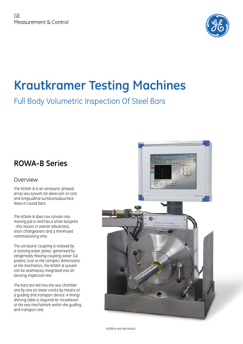
Krautkramer Testing Machines OverviewThe ROWA-B is an ultrasonic phasedarray test system for detection of coreand longitudinal surface/subsurfaceflaws in round bars.The ROWA-B does not contain anymoving parts and has a small footprint- this results in overall robustness,short changeovers and a minimizedcommissioning time.The ultrasonic coupling is realized bya rotating water jacket, generated bytangentially flowing coupling water (GEpatent). Due to the compact dimensionsof the mechanics, the ROWA-B systemcan be seamlessly integrated into anexisting inspection line.The bars are fed into the test chamberone by one on linear tracks by means ofa guiding and transport device. A lifting/shifting table is required for installationof the test mechanism within the guidingand transport line.Full Body Volumetric Inspection Of Steel Bars ROWA-B test mechanicsROWA-B SeriesGE Measurement & ControlDimension dependent guiding bushes at the inlet and outlet sides keep the water jacket within the test chamber and determine its free diameter. Rubber sealings prevent water leakage during test and remove the water from the test object’s surface after the test.Depending on the application and object diameter, 4-12 phased arrayprobes with up to 128 elements each are arranged circumferentially in a chamber. Inspection and changeover For testing, a multiple number of neighbouring elements are controlled in parallel and form virtual probes. Due to sequentialactivation of virtual probes along thecircum-ference, the ROWA-B achieves100% coverage of the rotating soundbeam without mechanical proberotation.One key advantage of the ROWA-B is ashort changeover time. Within a widedimension range, no mechanical probeadjustment is necessary. Probes areadjusted electronically by recallingstored parameters – only the guidingbushes and the seals need to bechanged without the use of any toolsaccording to the diameter of thematerial under test.The field proven and reliable GEultrasonic electronics processes allsignals and carries out a separateevaluation according to flaw type andposition.Calibration The ROWA-B can be either calibrated manually or by means of a fully automated Reference Standard Manipulator (recommended). The Manipulator is seamlessly integrated into the overall system and is being controlled via the application software of the ROWA-B. Your Benefits • Fully automated calibration in less than15 minutes• Increase of adjustment repeatabilityby reduced Human Factor• Safe calibration procedure especiallywith larger diameter test barsGE Business Unit, LLC is a subsidiary of the General Electric Company. The GE brand, logo, and Lumination are trademarks of the General Electric Company. © 2015 GE Business Unit, LLC. The USG brand & Logix are trademarks of USG Interiors, LLC. Information provided is subject to change without notice. All values are design or typical values when measured under laboratory conditions.GEIT-60024EN (10/15)Patented rotating water jacket coupling Reference Standard Manipulator RSM130。
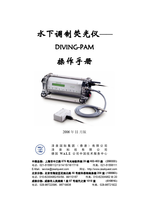
水下调制荧光仪——DIVING-PAM操作手册2006年11月版泽泉国际集团(香港)有限公司 泽 泉 科 技 有 限 公 司 德国WA L Z 公司中国技术服务中心中国总部:上海市中江路879号天地软件园28幢402-403座 (200333)电话:021-********/13/14/15/16/17/18 传真:021-********E-Mail :sevice@ 网址:北京分部:北京市海淀区花园北路48号院华思特商务楼209室(100083)电话:010-********/53/58,89110167 传真:010-********转20成都分部:成都市人民南路1段97号现代之窗1018室 (610016)电话:028-********,86719836 传真:028-********目录1 安全指导...................................................................................................................................- 4 -1.1 一般安全指导................................................................................................................- 4 -1.2 特殊安全指导................................................................................................................- 4 -2 光合作用与叶绿素荧光原理....................................................................................................- 5 -2.1 光合作用基本过程........................................................................................................- 5 -2.2 活体叶绿素荧光..........................................................................................................- 7 -2.2.1 叶绿素荧光的产生............................................................................................- 7 -2.2.2 叶绿素荧光诱导曲线........................................................................................- 8 -2.2.3 调制叶绿素荧光的测量....................................................................................- 8 -2.2.4 光响应曲线和快速光曲线..............................................................................- 10 -2.2.5 叶绿素荧光的暗弛豫......................................................................................- 10 -2.2.6 调制叶绿素荧光成像......................................................................................- 11 -3 DIVING-PAM简介..................................................................................................................- 12 -4 常用荧光参数.........................................................................................................................- 13 -4.1 Fo、Fm和Fv/Fm.........................................................................................................- 13 -4.3 Fm’.................................................................................................................................- 13 -4.3 Ft....................................................................................................................................- 13 -4.4 量子产量Yield.............................................................................................................- 13 -4.5 ETR和PAR..................................................................................................................- 14 -4.6 qP、qN和NPQ............................................................................................................- 14 -5 基础操作步骤.........................................................................................................................- 16 -6 按键操作.................................................................................................................................- 17 -6.1 单键操作......................................................................................................................- 17 -6.2 双键操作......................................................................................................................- 18 -7 数据存储功能.........................................................................................................................- 19 -8 MODE菜单介绍......................................................................................................................- 20 -8.1 MODE界面列表...........................................................................................................- 20 -8.2 MODE界面功能介绍...................................................................................................- 21 -9 DIVING-PAM的组成..............................................................................................................- 28 -9.1 主控单元......................................................................................................................- 28 -9.1.1 荧光的激发与检测............................................................................................- 28 -9.1.2 内置卤素灯.......................................................................................................- 29 -9.1.3 可充电电池.......................................................................................................- 29 -9.1.4 显示器...............................................................................................................- 30 -9.1.5 电子元件...........................................................................................................- 30 -9.1.6 接口介绍...........................................................................................................- 30 -9.2 标准光纤DIVING-PAM/F和微光纤DIVING-PAM/F1...........................................- 32 -9.3 光量子传感器..............................................................................................................- 32 -9.4 深度传感器..................................................................................................................- 33 -9.5 水温传感器..................................................................................................................- 33 -9.6 水下通用样品架DIVING-USH..................................................................................- 33 -9.6.1 介绍...................................................................................................................- 33 -9.6.2 应用方法:叶片状样品....................................................................................- 35 -9.6.3 应用方法:珊瑚、附着藻类等样品................................................................- 36 -9.6.4 应用方法:暗适应后测量Fv/Fm....................................................................- 37 -9.6.5 应用方法:测量叶片状样品吸收到的PAR...................................................- 38 -9.6.6 DIVING-USH的详细配件................................................................................- 39 -9.7 特殊叶夹/样品室.......................................................................................................- 40 -9.7.1 暗适应叶夹DIVING-LC................................................................................- 40 -9.7.2 表面样品室DIVING-SH(适合于珊瑚等0.................................................- 40 -9.7.3 磁性样品架DIVING-MLC(可选).............................................................- 40 -10 数据传输...............................................................................................................................- 42 -11 通过PC终端控制DIVING-PAM........................................................................................- 43 -12 维护.......................................................................................................................................- 44 -12.1 内置电池的更换......................................................................................................- 44 -12.2 卤素灯的更换..........................................................................................................- 46 -12.3 EPROM的更换........................................................................................................- 47 -12.4 保险丝的更换..........................................................................................................- 47 -12.5 清洁..........................................................................................................................- 47 - 附录1 技术参数......................................................................................................................- 48 - 附录2 警告和错误列表..........................................................................................................- 50 - 附录3 PIN分配.......................................................................................................................- 51 - 附录4 PC终端控制DIVING-PAM的命令列表...................................................................- 52 - 附录5 部分荧光基础理论文献...............................................................................................- 55 - 附录6 部分利用DIVING-PAM发表的文献.........................................................................- 59 -1 安全指导1.1 一般安全指导为避免触电,请不要拆开DIVING-PAM的主机。
Service Manual Saprom S909.0620.1-01ContentsSubject Page Machine3 Machine Elements3 Safety precautions4 Common Logic Functions5 Schematic S-Series6 Troubleshooting guide7 Pc-board DP-MAPRO8 Pc-board DMR11 Pc-board DS20BF13 Pc-board DK-DCDRV / DK-S3DRV16 Pc-board DK-PWRUP18 Pc-board PWRUP0419 Pc-board DP-S3NEFI20 Pc-board DK-GLCL21 Pc-board DP-UFI22 Pc-board DP-UFI-BO23 Pc-board DP-EMV23 Pc-board LSW24 Pc-board DS-VA24 Pc-board PP-90R25 Pc-board DS-ERW26 Control Transformer2723MachineMachine Elements*)option1torch9air intake2pressure reducer 10transport wheels 3gas cylinder*11main switch4tray area12display current/voltage 5facility for transport 13ground clamp6handle 14connector for ground cable 7front panel 15display cover8connectionsSafety precautionsRequirementUse and maintenance of welding and cutting machines can be dangerous. Please draw user´s attention to follow the safety precautions to avoid injuries. Welding and cutting machines must be used appro-priate and only by specialist staff. Please inform yourself constantly about the valid safety precautions and regulations of accident prevention by working with this machine.Only qualified workers who are knowledgeabel and have been trained to work safely with test instruments and equipment on energized circuits shall be permitted to perform testing work on electrical circuits or equipment were there is danger of injury from accidental contact with energized parts or improper use of the test instru-ments and equipment.Use only original spare partsReplace immediately any components that are not in perfect condition.NormsPlease follow the current safety regulations corresponding to your country.4Common Logic Functionscomponent function associated eventfan (power unit)on power modul temperature over 40°Cfan (power unit)off power modul temperature below 40°Cfan (cooling system)on after detection …welding current on“fan (cooling system)off after welding process, two minutes post-cooling timepump on after detection …welding current on“pump off after welding process, two minutes post-cooling timeGas test- press the buttons (arrow up) and “gas type“ (+) at the same time- the gas valve is activated for 30 sec.- a countdown is shown in the display- press button “gas type“ (+) again to end the test manuallyPump test- press the buttons (arrow up) and “material type“ (-) at the same time- the cooling pump is activated for one minute- a countdown is shown in the display- press button “material type“ (-) again to end the test manuallyReset adjustments- press the buttons (arrow up) and “TT Enter“ at the same time- all secondary parameters are reset to their default values- if Tiptronic is active, the settings of the current job are reset to their programmed values- all adjustments of the Extras menu remain unchangedMaster reset- press the buttons (arrow up) and “Mode“ together for about five sec.- the display shows “Master Reset“- the machine is reset completely to factory settingsCAUTION : all Tiptronic jobs are deleted5Schematic S-Series67Troubleshooting guide(*1) display the module temperatures in menu Extras > Diagnosis > Module temperatures (*2) display the supply voltages in menu Extras > Diagnosis > Operating voltages (*3) display the flow rate in menu Extras > Diagnosis > Flow rate cooling systemcode description reasonremovalE 00no programno welding parameters available for selected material-wire-gas combination (no reasonable combination)select other material-wire-gas combinationE 01thermal overload thermal sensor of power unit measures a too high tem-peraturelet machine cool down in standby (*1)E 02mains overvoltage mains voltage too high (24V supply > 36V)check mains voltage and control transformer (*2)E 03secondary overcurrent welding current is too highcheck pc-board LSWE 04air cooling errorTemp. sensor of the power unit detects that the unit heats up too fastcheck fan and air hardening limeE 05cooling system errorflowrate of the cooling liquid is too low (< 0,3 l/min) pump is not workingcheck connectors of flow-meter, level of cooling liquid and flowrate (*3)check fuse SI7 (2,5A) on pc-board DP-MAPRO E 06secondary overvoltage Master detects output voltage is too highexchange power unitE 07EEProm checksum errorno welding program stored or error during reading from memorytransfer welding programs to machine againE 08wire feed / tachopower consumption of wire feed motor too high no tacho signalno CAN-Bus connection between MAPRO and DMR blow out torch package with compressed air check wire feed unitcheck wiring of wire feed motor and pc-board DMR E 09error v/a measuring measuring difference between Master and Process check wiring of pc-board LSW and pc-board DK-UFI E 10torch socket / cableshort circuit of torch control cables or between torch switch wires and welding potential check torch control cables and torch interfaceE 11remote-control conn.short circuit between remote control cables check remote control and wiring of remote control socket E 12Communication ProcessProcess is not responding to Masterswitch the machine off and on againoptionally exchange pc-board DP-MAPRO E 13Temp. sensor error Temp. sensor is defective check resistor value and wiring of the sensor E 14Op. voltages error supply voltage is too low (< 17V)check mains voltage and control transformer (*2)E 16primary overcurrent protection1power consumption of power unti 1 is too highexchange power unitE 18overload protectionsafety shutdown to protect electrical components temp. sensor is disconnectedlet machine cool down in standby check temp. sensor E 20Overvoltage sec.Process reports a too high output voltageexchange power unitE 21Output voltage/currentexternal current/voltage or measure-difference between Master and Processexchange power unit E 22Mains undervoltage 1 power unit 1 reports mains voltage too low check mains voltage and mains rectifier E 23Mains overvoltage power unit reports mains voltage too high check mains voltage E 24Overcurrent protection2power consumption of power unti 2 is too high exchange power unitE 25Power module detection Jumper on pc-board DK-DCDRV have been set wrong check junper J1, J2 on pc-board DK-DCDRV E27no program (DSP)welding programs faulty or not availableselect other material-wire-gas combination transfer welding programs to machine again E 30Mains undervoltage 2 power unit 2 reports mains voltage too low check mains voltage and mains rectifier E 31Communication errorMaster is not responding to Processswitch the machine off and on againoptionally exchange pc-board DP-MAPROPc-boardsPc-board DP-MAPROThe pc-board DP-MAPRO is responsible for the welding sequence and is managing the process control of the S-Series.(MAPRO = MA ster-PRO cess)Functions- Logicfunctions of the welding process- generating and monitoring supply voltages- driving powerup-relais- driving power unit/units- monitoring control and operating elements (DS20BF, remote control, torch buttons)- driving fans- driving coolingpump- monitoring flowmeter- monitoring mains- and output voltage- generating signal …welding current on“- managing communications between PC and machine- managing and storage of all welding parameters- CAN-busLED displays :normalLED state designation1 (green)flashing (half freq. of LED5)CPLD-processor ok2 (red)off D igital S ignal P rocessor (DSP) ok3 (green)on supply voltage 3,3V DC ok4 (red)off micro controller ok5 (green)flashing DSP is working6 (green)flashing micro controller is workingmalfunctionLED state designation1 (green)never on CPLD-processor is not working2 (red)on DSP is not working3 (green)off supply voltage 3,3V DC is missingcheck 18V~ AC of control transformer X2/1 X2/24 (red)on micro controller is not working5 (green)never on DSP is not working6 (green)never on micro controller is not workingIf the LEDs are indicating a malfunction which can not be relieved by switching the machine off and on again, it is recommended that the pc-board DP-MAPRO is exchanged.89Settings DIP SwitchIf the machine is to be programmed via the serial port, the DIP switches 1-3 has to be set to “ON“. In normal operation they has to be set to “OFF“.If the pc-board is used in a Saprom S3 mobile, the DIP switch 4 has to be set to “ON“. For the use in a standard Saprom S3, S5 or S8, DIP switch 4 has to be set to “OFF“.Overview fuses DP-MAPROfuse value [A]Safeguarding Si 61fans (power unit)Si 72,5cooling pumpMeasuring Pointsdesignation measure pointresult solenoid valve X10/1X10/2+GND +24V DC supply voltage control transformer X6/1X6/3~~230V AC supply voltage fan group 1X7/1X7/2~~230V AC supply voltage fan group 2X25/1X25/2~~230V AC supply voltage cooling pump X13/1X13/2~~230V AC supply voltage control transformerX2/1X2/2~~18V AC X2/3X2/4~~42V AC supply voltage flow meter X9/1X9/3+GND +15V DCsupply voltage CAN busX8/1X8/2GND ++15V DC X14/1X14/2GND ++15V DC X20/1X20/2GND ++15V DCDIP switchONOFF1mode seriel programming mode normal operation 2mode seriel programming mode normal operation 3mode seriel programming mode normal operation 4configuration S3 mobileconfiguration S3, S5, S8Picture Pc-board DP-MAPRO10Pc-board DMRThe pc-board DMR is the wire feed motor control of the machine.Functions- control and monitoring wire feed motor- driving solenoid valve- control and monitoring of operating elements (DS20BF, remote control, torch buttons) - monitoring wire insert button- supply pc-board PP90R (Push-Pull)LED displaysnormalLED state designation1 (red)off microcontroller ok2 (green)on supply voltage 5V okmalfunctionLED state designation1 (red)is lit weak microcontroller not programmedflashes malfunction CAN bus2 (green)off supply voltage 5V not okMeasuring pointsdesignation measure point resultsolenoid valve X6/1X6/2+GND+24V DCsupply voltage Tacho X5/1X5/3+GND5V DCdrive level for pc-board PP90R (Push-Pull)X7/1X7/3+GND+24V DCwire insert button (when button pressed)X1/1X1/20Ωwire insert button (when button pressed)X4/1X4/20Ωsupply wire feed motor X10X11-+0-42V DCsupply voltage CAN bus X20/1X20/2GND++15V DCPc-board DS20BFThe pc-board DS20BF is the front panel with all buttons, rotary impulse encoder and all displays.Functions- operating/setup the machine- display of all welding parameters- display error messages- display machine parameters (version operating system, actual values etc.)Picture Pc-board DS20BFAt a machine with separated front panels, the pc-boards DS21BF and DS22BF are used.Display testThe display has a internal function test. To execute the test press the buttons …-“ (TA13) and …manual mode“ (TA4) at the same time. Now the LCD-Display shows …Display Test“ and the version number of the operating system. Press any button to start the first test, where all LEDs and the LCD-Display are turned on and off al-ternately. The LCD-Display shows …LEDs on, Backlight off“.Press any button to go to the next test. In this test all buttons are checked, by pressing all 12 buttons one after another. The button which is to be pressed, is indicated by a lit LED. After that the rotary impulse encoders are checked. The LCD-Display shows a cursor which can be moved by the rotary impulse encoders. At first the cursor has to be moved to the left with the left rotary impulse encoder then to the right. After that the cursor has to be moved to the left and right with the right rotary impulse encoder.Then the test are completed and the LCD-Display shows …End of Tests“ and the machine goes back into normal mode, which was displayed before the display test was executed.Pc-board DK-DCDRV / DK-S3DRVThe pc-board DK-DCDRV is managing the primary drive level of the power unit Saprom S5 and S8. The pc-board DK-DCDRV is managing the primary drive level of the power unit Saprom S3. Functions- encoding power unit- connection temperature sensor of heat sink- supply pc-board LSW- monitoring DC link voltage and supply voltage- safety shut-down of power unit- passthrough signal powerup relais- passthrough signal …welding current on“ (from pc-board LSW)Encoding Power Unitjumper J1jumper J2setting machine type00240 A S501270 A S310300 A S811reserved0 = contact open1 = contact closedIf DIP switches are used instead of jumper: 0 = “OFF“, 1 = “ON“LED displaysnormalLED state designation1 (red)off primary overcurrent shut down2 (green)on drive level of low-side is ok4 (green)on DC link voltage max is ok5 (green)on drive level of high-side is ok6 (green)on DC link voltage min is okmalfunctionLED state reason1 (red)on primary current is too high, power unit has been switched off2 (green)never on no drive level low-side4 (green)off DC link voltage is too high (e.g. mains overvoltage)5 (green)never on no drive level high-side6 (green)off DC link voltage is too low (e.g. mains voltage too low)Measuring PointsPicture Pc-board DK-DCDRV / DK-S3DRVdesignationMesspunkt Messergebnis supply voltage pc-board LSWX2/1X2/6+GND 15V DC supply voltage pc-board LSWX2/3X2/6-GND -15V DC thermal sensorX3/1X3/2GND +10k Ω at 25°C (about +2V DC)Pc-board DK-PWRUPThe pc-board DK-PWRUP is the power up-circuit of the Saprom S3.Functions- reducing start-up peak current for capacitors - supply and safeguarding of control transformerMeasuring PointsPicture Pc-board DK-PWRUPFusesSafeguarding the control transformer via Si1, Si2 : each 4A idleBeschreibungMesspunktMessergebnis mains input L1 mains input L2 mains input L3X5X6X7~~~400V ACmains output L1 mains output L2 mains output L3X1X2X3~~~400V AC supply voltage control transformer X10/1X10/2~~400V AC drive level relayX4/1,3X4/2,4+-24V DCPc-board PWRUP04The pc-board DK-PWRUP is the power up-circuit of the Saprom S5 und S8.Functions- reducing start-up peak current for capacitors - supply and safeguarding of control transformerMeasuring PointsFusesSafeguarding the control transformer via Si1, Si2 : each 4A idledesignationmeasure pointresult mains input L1 mains input L2 mains input L3X5X6X7~~~400V ACmains output L1 mains output L2 mains output L3X1X2X3~~~400V AC supply voltage control transformer X10/1X10/2~~400V AC drive level relayX4/1,3X4/2,4+-24V DCPc-board DP-S3NEFIThe pc-board DP-S3NEFI is the mains filter and power up board of the Saprom S3 mobile.Functions- mains filter- reducing start-up peak current for capacitors - supply and safeguarding for control transformerMeasuring PointsPicture pc-board DP-S3NEFIFusesSafeguarding the control transformer via Si3, Si4 : each 4A idledesignationmeasure pointresult mains input L1LP1~400V AC mains input L2LP2~400V AC mains input L3LP3~400V AC drive level power-up relais X4/1, X4/3X4/2, X4/4+-+24V DC GND supply control transformer X10/1X10/2~~400V AC mains output L1LP4~400V AC mains output L2LP5~400V AC mains output L3LP6~400V ACPc-board DK-GLCLThe pc-board DK-GLCL is for wiring the secondary rectifier diodes.Functions- wiring- pulse smoothingPicture pc-board DK-GLCLPc-board DP-UFIThe pc-board DK-UFI is for wiring the welding sockets.Functions- wiring welding sockets - providing output voltageMeasuring pointsSince the following serial no. the pc-board DP-UFI was replaced by the boards DP-UFI-BO and DP-EMV:designation measure pointresult secondary output voltage(nm MMA mode)X3X2+GND ca. 81V DC socket …+“socket …-“+GND ca. 81V DC X1/1X1/2+GNDca. 81V DCmachine serial no.date Saprom S3405-1525-00122.06.2005Saprom S5403-1525-00122.06.2005Saprom S8404-1525-00122.06.2005Saprom S3 mobile406-1524-00124.06.2005Pc-board DP-UFI-BOFunctions- wiring welding sockets- providing output voltagePicture Pc-board DP-UFI-BOPc-board DP-EMVFunctions- EMC filterPicture Pc-board DP-EMVPc-board LSWThe pc-board LSW is a potential free current sensor.Functions- measuring the welding currentMeasuring pointsPicture Pc-board LSWPc-board DS-VADigital displayFunctions:- display nominal and actual values of welding voltage and welding current - hold-function of the last welding valuesLED displaysPicture Pc-board DS-VA:designation measure pointresult supply voltageX1/1X1/3-++30V DCnormalLED state designation41 (green)onhold-function activePc-board PP-90Rmanagement for Lorch Push-Pull torches.Functions:- supply Push-Pull motor - managing start signalMeasuring points:Picture Pc-board PP-90R:designationmeasuring pointresultsupply voltage X1/2X1/5~~42VAC motor voltage X1/4X1/1-++60VDC drive level relayX1/7X1/6GND ++24VDCPc-board DS-ERWThe pc-board DS-ERW is the extension pc-board for machines with additional wire feed case.Functions- switching between wire feed 1 / wire feeder 2- driving solenoid valve - driving water valvesLED displaysMeasuring PointsnormalLED state designation1 (green)off wire feed unit 1 active onwire feed unit 2 activedesignationmeasuring pointresultsolenoid valve 1X5/1X5/2GND +24V DC solenoid valve 1X6/1X6/2GND +24V DC water valve 1X7/1X7/2~~42V AC water valve 2X8/1X8/2~~42V ACControl TransformerThe control transformer 655.8021.0 is used in Saprom S3, S5 and S8. Te control transformer 655.8023.0 is used in Saprom S3 mobile.。


姿态仪终端操作说明一、 主界面介绍如右图:1)优化测试:针对天线调整部分数据的测试入口;2)优化记录查询:优化测试保存后的数据存储在其中;3)开站测试:新开站点的宏站天线测试及数据存储、查询入口;4)单验测试:单验站点的宏站天线测试及数据存储、查询入口;5)天气状况:(需联网)可查询当前天气信息;6)售后服务:售后技术支持电话;7)系统设置:设备校准、区域设置、基础数据更新等设置入口;二、 优化测试步骤说明:优化测试的基站基础数据来源于亿阳平台,进行此类测试时,需确保设备连接在中国移动的网络下(如:移动手机热点或给设备的SIM卡槽1中插入移动SIM卡)1)测试基站搜索:点击进入【优化测试】,点击【选择】,输入站点名称关键字后点击搜索按键,搜索完成后则显示包含所有关键字的站点列表,选择待测站点(站点信息前面会显示搜索到的站点的网络制式及对应地市信息);2)基准定位完成步骤1)后点击左下角【基准定位】按键进行基准定位操作,完成时设备会提示成功,则点击确定后返回即可;基准定位操作是给挂高值取最低点的基准零值,因此在操作【基准定位】时需至基站位置的最低点位置(如:楼顶站点的最低位置为建筑物所处位置的一楼地面;铁塔站点的最低位置为铁塔地基所在的地面)进行基准定位获取挂高值的初始值。
基准定位完成后会在按钮旁边显示定位完成的时间,建议在此时间基础上延后30分钟完成天线测试,以确保精度;3)一键测试到达天线待测位置(正常应可单手近距离摸到天线的距离)选择【天线测试】,会显示该基站下所有天线信息,选择需测试的天线进行选择后进入测试界面;测试标准测试手法:点击【启动】后如下图中手持设备进行5次划八字消磁动作,在偏离抱杆等铁件的位置伸直手臂并竖直(是否竖直可参考仪表界面上的俯仰角是否在±5°以内)举起仪表(此时建议确认仪表中磁场干扰值低于55,若高于时则再次进行划八字法消磁并寻找天线附近的其它位置进行竖直举起动作),如下图,当仪表语音提示“请平移至天线中部”时,请匀速移动仪表并贴至天线中部,仪表提示“测试完成”时,撤回仪表,则所有参数测试完成;若实测值与亿阳后台值偏差超出省公司要求,将会有图一弹窗提示图一 图二图二中红框部分为测试值与后台数据的具体偏差情况;注意:“电调下倾角”需进行手动填写后才允许保存。
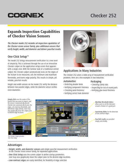
Checker 252Expands Inspection Capabilities of Checker Vision SensorsOne-Click Setup ™Applications in Many IndustriesThe Checker model 252 includes all inspection capabilities of the Checker vision sensor family, plus additional sensors that verify height, width, and diameter and deliver pass/fail results.Min/Max threshold sliders allow users to set the tolerance around a feature of a good part.Sensitivity Slider for the detection of low-contrast edges.Pass/fail results are provided simply and reliably.The Checker Caliper provides One-Click setupThe model 252 brings measurement verification to a new level of simplicity. This is achieved through the use of an innovative Checker caliper on the application setup screen that appears with a single click. With the familiar look of a traditional vernier caliper, the Checker caliper automatically locks on the edges of the feature to be measured, sets the minimum and maximum thresholds, and learns edge polarity. This results in simple, yet reliable, pass/fail results.Height and width sensors on the model 252 verify the distance between two parallel edges, while the diameter sensor verifies circle diameters.The Checker 252 solves a wide array of measurement verification problems. Here are a few examples in two industries:Automotive•Detecting double feeds•Verifying component thickness •Checking weld thickness•Verifying correct hole diameterAdvantages•Height, width, and diameter sensors add simple pass/fail measurement verification to the Checker vision sensor family, for expanded applications•One-Click Setup uses the screen caliper to define startup parameters.User may also graphically move the caliper jaws to the desired edge locations •Low-contrast edges are easily identified, for flexibility of edge selectionPackaging•Checking safety tabs•Inspecting for out of round parts •Verifying glue bead thicknessalso graphically move the caliper jaws to desired edge locations.are trademarks of, Cognex Corporation. All other trademarks are the property of their respective owners. Printed in the USA. Lit. No. ML4004-1008CHECKER 252 VISION SENSORLIGHTING IlluminationWhite LEDEXTERNAL TRIGGER INPUT Input ON > 10VDC (> 6mA)Input OFF < 2VDC (< 1.5mA)Protection Opto-isolated, polarity-independentOUTPUTSOutput Solid state switchRating 100mA, 24VDC Max voltage drop 3.5VDC @ 100mA Max load 100mA Protection Opto-isolated, protected from shortcircuit, overcurrent, and reverse polarity ENCODER INPUTS Encoder type 300 kHz (max) quadrature encoder.Open collector and differential output ON/OFF 50% nominalLoad 50% encoder maximumTERMINATION12-Pin M12 connector , USB Mini-B receptaclePOWER Voltage +24VDC (22-26VDC) Current 250mA maxMECHANICAL Dimensions 67mm (2.64in) H x 41mm (1.61in) W x 60mm (2.36in) D Weight100g (3.5oz)MODES OF OPERATIONInternal part trigger, external part trigger, free running ENVIRONMENTALOperating temperature 0° to 50°C (32° to 122°F)Storage temperature -30° to 80°C (-22° to 176°F)Operating humidity 0%-90%, non-condensing Operating altitude 4000m maximum Shock 80Gs for 5ms on each axis (per IEC 68-2-2)Vibration 10Gs (10-500Hz) per IEC 68-2-6Protection IP67CERTIFICATIONS CE, c CSA us, FCC, RoHSMINIMUM PC REQUIREMENTS (Only required for setup)Operating systemsMicrosoft Windows Vista ™,XP ™, or 2000™SP4RAM 128 MB RAM USB USB 1.1 (2.0 recommended forbest performance)Screen resolution 1024 x 768 (96 DPI) or1280 x 1024 (120 DPI) display PART NUMBERSPart Number I/O Cable Included CKR-252-001Flying Leads CKR-252-002I/O Box Included accessories •5.8mm lens •Checker software CD •Standard USB cable •USB connector cover •Quick Start Guide •Mounting screws •Allen wrench (for focus lock)Optional AccessoriesCKR-200-IOBOX-002Checker I/O box CKR-200-BKT Adjustable bracket CKR-200-LENSKIT Lens Kit CKR-200-CBL-USB IP67 USB cable CKR-200-CBL-EXT I/O extension cable (5m)CKR-200-CBL-RT-003Right-angle cable (1m)SV-350-000SensorView ™350 panel-mount displayFor more information, please visit /checker252Companies around the world rely on Cognex ®vision to optimize quality and drive down costs.Curves show the field of viewfor standard and optional lenses. Each grid square = 1in (2.54cm)Working DistanceF ie l do f V ie wField of ViewChecker 252 Vision Sensor123456cm inin 0024681012141618202224262830789101112212345646810121416001820227893.6m m 5.8mm8m m16m m60mm67mm (2.64in)39mm 41mm (1.61in)。

Operating Manual CENTOR EASY GaugeOperating ManualCENTOR EASYV3.39ANDILOG Technologies - BP62001 - 13845 Vitrolles Cedex 9 - FranceE-mail : **************** Web : Ph : +33(0)442 348 340 – Fax : +33(0)442 348 349I. Presentation (2)II. Handling (2)III. Recommendation before first use (2)1. Sensor (2)2. Test Stand (2)3. Conditions (3)4. Battery (3)IV. Presentation of your force gauge (4)1. Front panel scheme (4)2. Starting your force Gauge (5)3. Display mode (6)4. Zeroing (6)5. Measure unit (7)6. Peak values (7)7. Backlit (7)V. Advanced features (8)1. Limits (9)2. Display (10)3. IN / OUT (11)4. RS232 (12)5. Statistics and memory (13)6. System (15)VI. Associated products (16)1. Manual or motorised test stands (16)2. Gripping accessories (16)3. Acquisition software (16)4. Interface Cables (16)VII. Appendices (17)1. Key action (17)2. Save and load a setting (17)3. Error Messages (17)4. Factory Settings (18)5. Connections (19)6. Dimensions (20)Revision Date Description3.39 06.06.2016 Subd 15 I/0Rev. 3.30 12.11.2013I.PresentationThank you for choosing the CENTOR Touch gauge manufactured by Andilog Technologies.This force gauge is the result of 25 years experience in force and torque measurements with new electronic technologies offering a higher-performance and more reliable instrument.Though it is a very comprehensive instrument, the CENTOR EASY force gauge is easy to use. This instruction manual will guide you to set your first measurements.II.HandlingCAUTION - Unpacking: Your CENTOR EASY force gauge has been supplied in its carrying case. Check that it has not been damaged during transportation. If you have any doubt, please contact us, and our service support will you guide you through simple checks to ensure that the gauge has not been damaged.Unpacking:The CENTOR EASY force gauge is supplied with:•Carrying case•Extension rod (Internal sensor only)•Hook (Internal sensor only)•Compression plate (Internal sensor only)•Power plug adaptor•Certificate of calibrationIII.Recommendation before first use1.SensorNever connect accessories (hook, plate . . .) directly to the sensor rod. Use theextension rod delivered with your instrument.In spite of its mechanical protection, sensor overload can damage the instrument. Theinstrument stops if the capacity has been exceeded 10 times. You have to return it toANDILOG TECHNOLOGIES for checking.It is important that measured values are under 90% of the sensor capacity.2.Test StandThe gauge can be affixed to a test stand via two M5 screws, which should not extend through the back cover more than 3 mm. Please contact ANDILOG Technologies if you need more information or if you need a fixture to mount your force gauge to a test stand.3.Conditions•Working Temperature: 0°C to +35°C•Stock Temperature: -20°C to +45°C•Humidity: 5% to 95%•Altitude: 3000m4.BatteryThe battery life is 8 hours under a normal use. The gauge should be charged after normal use. You should charge it every 3 weeks, to ensure a maximum life time of the batteries.It is recommended to use the original power adaptor supplied by ANDILOG Technologies. The power adaptor has the following specifications: 12V, 0.85AIV.Presentation of your force gauge1. Front panel scheme2. Starting your force GaugePress the I/O button the information screen showing the status of the CENTOR force gauge is displayed during 5 seconds, and then the main screen is displayed.3. Display modeWe describe here the screen following manufacturer settings, prepared by ANDILOG for delivery.Note: On line 1 and line 2 you can display the following:• VLI : current value • MXI: Maximum • MNI: Minimum4. ZeroingThe “ZERO” button allows for the tare. The gauge will take into consideration the weight of accessories (hook or plate) fixed on the sensor’s rod.Pressing this button reset all memories, especially peak values.NOTA: When turned on the CENTOR achieves several tests, especially to check the sensor’s good state of health. It is possible to leave tools fixed on the force gauge, but the total weight must notexceed 20% of the sensor’s maximum capacity.5.Measure unitTo change the measure unit, just press “UNIT” button.When the force gauge is tooled up with an external sensor, it detects the type of sensor connected and displays the corresponding units.6.Peak valuesThe CENTOR automatically calculates peak values (maximum and minimum) and systematically displays them on line 2. Pressing “MAX” button makes max. value, min. value and current value successively display (as well as a calculation if it has been set).7.BacklitYou can turn on the backlit by pressing “” button.When using the force gauge on battery, the backlit turn automatically off after 3 min of operating. The total autonomy of the CENTOR will be reduced when the backlight is turned on.When the gauge is used with the power plug, the backlight does switch off by pressing back on the backlight button.V. Advanced featuresCENTOR force gauge has several functions and settings, which makes it well adapted to the achievement of any test.To optimize the force gauge operation compared to your application, we will study all the setting possibilities hereafter.Parameters can be set via the setting menu by pressing the “” button.The setting screen appears and the keyboard functions change:Settings screen:To move within the menu, uses “ MAX ” and “ UNIT” buttonsTo select the required function, highlights it and press the “ ►TDX” button. To exit uses “M” button.In the following screens, the operating mode is the same, however, in any other screen whatever the position of the cursor:“X”: switches to the previous screen cancelling the modifications. “M”: switches to the previous screen and saving the modifications.Let see the force gauge functions one by one:1. LimitsThresholds allow defining limits and actions achieved by the force gauge when the limit value set is reached.From Menu, highlight “LIMITS” and select with “ TDX ” button.From this screen you can choose to activate this feature.Display “YES” or “NO” (using TDX and ZERO buttons) to activate or deactivate this feature.Once the feature is activated, the parameters are displayedIn the main measuring screen, the status line is modified: signs <<, = , >> are displayed, they display ifthe value is inside or outside the limits.You can display the word “FAIL” or “PASS”; the setting is done in the “DISPLAY” menu.Note: This feature allows activating a TOR output on the 15 pins connector on the side of your device. The setting is done through the IN/OUT menu. (You can by example send a STOP signal to a motorized test stand)Note: If only one threshold is necessary, max value for example, enter the max or min capacity of the sensor for the second threshold value.2. DisplayExit by pressing the “M” button to save your parameters. From this menu you can entirely set the main screen.CAUTION: if Auto-off displays NO, we advise you to use the force gauge with the charger to avoid the measuring process being interrupted because of low battery condition.3. IN / OUTThe Centor EASY force gauge is equipped with a SubD15 pinsconnector on the side. You can use this connector to connect it to an external device in order to communicate. (See the appendix for pin numbers). You can either:• Pedal: input to perform an action to the force gauge • Top1: output sending signal 0 or 1 when threshold isreached• Anal: analogue output at 100Hz on 10bits • Digi: digimatic output, by example for printer• RS232: input/output sending current values continuously,per request (pressing TDX button) or per computer actionMenu ChoicesDescriptionPedal TAR, MAX, TDXSet the action of the pedal. It use a substitute to the action of pressing a front panel button : ZERO (TAR), MAX or TDXTop1O, F, I+, I-, M+, M- Set the signal type sent through the TOR output :positive impulsion (I+), negative impulsion (I-), Change to positive state (M+) change to negative state (M-), Open (O), Closed (F)Anal INT, NO Active or de-active the analog outputDigi NO, VLI, MXI, MNI Active the Digimatic output and set the value : currentvalue (VLI), maximum (MXI, minimum (MNI)RS232NO, IMP, CON Set the RS232 output and its type : continuous or perrequest imp (pressing TDX on the front panel button)Menu ChoiceDescriptionLINE 1 VLI, MXI, MNISet the display of the first line 1 : current value (VLI), Maximum (MXI), Minimum (MNI)LINE 2 NO, VLI, MXI, MNI Set the display of the second line 2 : None (NO), currentvalue (VLI), Maximum (MXI), Minimum (MNI)SIGN NO, TRA, COM Set if the sign is displayed and if yes the direction of thepositive sign : tensile (TRA) or compression (COM)DECIMA 0,1, 2, 3, 4 Number of decimals BARGRA YES, NO Display the bar graph or notGONOGO NO, PAS, FAI Display or not the word PASS or FAIL when the limit isreachedDIRECT H, B determines the direction of display, caution: the frontpanel buttons are not affected by this parameterAUTOFFNO, 5, 10, 15 Determines if force gauge stops if no button isactivated after 5, 10, 15 min.4.RS232The first part of the screen defines the parameters of RS232communication and can be modified via and buttons.They must be identical to your computer settings.Menu Choices DescriptionBds 2400, 4800, 9600,19200 Speed of the RS232 connexion.Par SANS, PAIR,IMPAIRParityBits INT, NON Activate or de-activate theanalogue outputDigi 8 Number of bitsStop 1, 2 Number of stop bitsThe second part defines the characters sequence sent:Menu Choice DescriptionDemand F Current ValueP maximumV minimumC InactiveT Last 100 values in memoryW InactiveA InactiveThe last part defines the accessories data that you can send:Menu Choice DescriptionCR YES, NO Send a carriage returnLF YES, NO Send a newlineSign YES, NO send the sign of the valueUnit YES, NO send the unitDatHour YES, NO Send the date and hour of the value5. Statistics and memoryThe Centor Easy has a mode called “Statistical” allowing to perform a series a measurements and get quickly the mean and standard deviation.a. LimitationThe memory of the force gauge is limited to 100 measurements; beyond it will be necessary to clear the first results to be able to add new ones.b. AccessAccess to this mode by: pressing “M” button, moving the cursor down to reach the line called “STATS” and entering the sub-menu by pressing the right arrow TDX button.c. DisplayIf no action has been carried out on SATS submenu, the screen allows youto configure three parameters: • Mes/Samp: Number of measurement per sample • Oper: Personal ID number of the operator • Unit: Measurement unit If measurements are saved in the memory, those three parameters are no longer available. The only way to access it again is by clearing thememory.If measurements are saved, they are displayed at the bottom of the page, the cursor can move in the table. The displayed data are as follow: • The first number indicated the sample number, the second number is the measure itself • If your samples contains more than one measurement (see parameter (Mes/Sample) so you have multiple rows with the same sample number Also 3 statistical calculations are displayed: • Mea: Average of the series of measurements • StDev: standard deviation of the series of measurements • S/M: Standard deviation divided by the averaged. Possible actionsIf no data are saved, you can configure the three parameters described above. To do so place the cursor on the parameter and change the settings with the left and right buttonIf data are saved, you can:• Review the result, moving the cursor in the table: up and down keys • Delete the selected sample or the entire series: left button (ZERO) •Send data : right button (TDX)e. Erasing ProcedurePress the left button (ZERO) to erase the selected sample or the complete set of measurements. If your sample includes several measures, they will be all deleted. A sub menu is displayed, asking what need to be deleted: • Clear the selected sample: left (ZERO) • Clear the entire series: M button • Do not erase: X button Note: It is strictly impossible to recover deleted dataf. Switch to the measure modeTo start recording your measurements and using the statistical mode of the maximum values, press the X button and you will go directly to the measurement mode.Press the M key to return to the main menu of the Centor without saving.g. Measuring ModeThe measurement is performed by applying a force to the pressure sensor Centor. At any time the maximum is displayed in large characters on line 1. You can if you wish, display the current value instead of the maximum by pressing the top button (MAX).When a measurement was made press right (TDX) to validate and save or left button (ZERO) to cancel and delete.Once the measurement is recorded or deleted, the device is ready to perform a new measurement.When you reach the maximum of 100 values, pressing the right key (TDX) no longer has any effect and a warning s is displayed. The memory is full.Note that unlike the conventional use of the Centor unit is locked and will remain as you have set throughout your measurements. By pressing the UNIT key will have no effect.h. Return to the STATS menuTo return to the STATS sub menu and displayed the results, press the M button.Note: If you turn OFF the device will using the STATS mode, he will remains in the same mode when turn it back ON, and pressing the M key will display the STAT sub menu.6.SystemThe following settings can be set: Date, Hour and LanguageVI.Associated products1.Manual or motorised test standsTo ensure a precise measurement, it is important that your CENTOR force gauge is placed in the axis of the force throughout the test. To ensure this placement is correct, ANDILOG and ANDILOG TECHNOLOGIES have developed a complete range of simple and sophisticated test stands.These are manual or motorised test stands, some of them being computer-controlled.If you want more information about test stands, contact your ANDILOG TECHNOLOGIES dealer or visit our web site .2.Gripping accessoriesANDILOG TECHNOLOGIES offers a series of gripping accessories adapted to different tests: hooks, plates, pliers, self-squeezing jaws, eccentric jaws, peeling fixture, etc…If you want to receive our catalogue, contact your ANDILOG TECHNOLOGIES dealer.3.Acquisition softwareANDILOG TECHNOLOGIES has developed several programs to save and analyse values.You want to analyse values on a chart: RSIC software has been developed to this.You want to capture the values graph and use graphics tools: CALIGRAF software goes further in tests analysis.4.Interface CablesSeveral interface cables can be used with CENTOR Easy force gauge:External pedal: allows simulation of a keyboard buttonCable for analogue link (with male-female plugs): links your gauge to another systemCable for Digimatic link: connect your gauge to a statistical printerCable for RS232 link: connect your gauge to a computer using the RS232 outputVII.Appendices1.Key actionButton Measure Mode Menu ModeON/Off Turn On & Off your device Turn On & Off your deviceM Access to the menu mode Exit and SaveO Backlight BacklightX Inactive Exit without savingUpMAX Change the value displayed online 2TDX Send data through RS232 orRightsave data to the STAT modeUNIT Change the measurement unit DownZERO Zeroing the force gauge Left2.Save and load a settingYou can store a configuration, and reload it at any time. To do so, press the M key to go to the Menu mode then:•Press ZERO and M to save the configuration•Press TDX and M to reload the saved configuration•Press X and M to load the factory configuration3.Error MessagesThe AUTOTEST screen displays if:•The device detects a minor or major default when it starts•In the SYSTEM sub menu, by pressing the keys: M and MAXa.Minor defaults•Low battery level•Calibration is due•Backup battery is out of orderPress the MAX key to continueb.Major defaults•Load cell is out of order: “Off” value is higher than 3%•Counter of overload reach its maximum value: “OVERL” value is higher than 10•Internal errorPlease contact ANDILOG4.Factory SettingsFeature Value LIMITSChanel NO DISPLAYLINE1 VLILINE2 MXISIGN TRADECIMA 4BARG YESRAFF NDIRECT HAUTOFF 10 IN/OUTPEDALE RAZTOP1 FANAL NODIGI NORS232 NO RS232Bds 9600Par NoneBits 8Stop 1Demandd FCR YESLF YESSigne YESUnite NODatHeur NO5.ConnectionsDetail of connector SubD 15 points of CENTOR electronic cardPIN 1 Not connected2 Reset To be connected to Ground for reset3 RS232 TXD4 RS232 RXD5 Digimatic6 Digimatic7 Digimatic8 Digimatic9 Output Force N°110 Output Force N°211 Input Force N°112 Input Force pedal13 GROUND14 Analogue output15 GROUNDOperating Manual – V3.39 CENTOR EASY Force Gauge- 20 -6. Dimensions。

w w w . slamt ec. comRPLIDAR A2 Low Cost 360 Degree Laser Range Scanner Introduction and DatasheetModel: A2M12OPTMAG16K2022-04-08 rev.1.0CONTENTS (1)INTRODUCTION (3)S YSTEM CONNECTION (3)M ECHANISM (4)S AFETY AND S COPE (6)D ATA O UTPUT (7)H IGH S PEED S AMPLING P ROTOCOL AND C OMPATIBILITY (7)A PPLICATION S CENARIOS (8)SPECIFICATION (9)M EASUREMENT P ERFORMANCE (9)L ASER P OWER S PECIFICATION (9)O PTICAL W INDOW (10)C OORDINATE S YSTEM D EFINITION OF S CANNING D ATA (10)C OMMUNICATION INTERFACE (11)MISC (14)SELF-PROTECTION AND STATUS DETECTION (15)SDK AND SUPPORT (16)MECHANICAL DIMENSIONS (17)REVISION HISTORY (18)APPENDIX (19)I MAGE AND T ABLE I NDEX (19)IntroductionThe RPLIDAR A2M12 is the next generation low cost 360 degree 2D laser scanner (LIDAR) solution developed by SLAMTEC. It can take up to 16000 samples of laser ranging per second with high rotation speed. And equipped with SLAMTEC patented OPTMAG technology, it breakouts the life limitation of traditional LIDAR system so as to work stably for a long time.The system can perform 2D 360-degree scan within a 12-meter range. The generated 2D point cloud data can be used in mapping, localization and object/environment modeling.The typical scanning frequency of RPLIDAR A2M12 is 10Hz(600rpm), and the frequency can be freely adjusted within the 5-15Hz range according to the specific requirements. With the 10Hz scanning frequency, the sampling rate is 16kHz and the angular resolution is 0.225°.Due to the improvements in SLAMTEC hardware operating performance and related algorithm, RPLIDAR A2M12 works well in all kinds of indoor environment and outdoor environment without direct sunlight. Meanwhile, before leaving the factory, every RPLIDAR A2M12 has passed the strict testing to ensure the laser output power meet the eye-safety standard of IEC-60825 Class 1.System connectionThe RPLIDAR A2M12 consists of a range scanner core and the mechanical powering part which makes the core rotate at a high speed. When it functionsnormally, the scanner will rotate and scan clockwise. And users can get the range scan data via the communication interface of the RPLIDAR and control the start, stop and rotating speed of the rotate motor via PWM.Range Scanner CoreCommunicationand PowerInterface MechanicalPowering PartFigure 1-1 RPLIDAR System CompositionThe RPLIDAR A2M12 comes with a rotation speed detection and adaptive system. The system will adjust the angular resolution automatically according to the actual rotating speed. And there is no need to provide complicated power system for RPLIDAR. In this way, the simple power supply schema saves the BOM cost. If the actual speed of the RPLIDAR is required, the host system can get the related data via communication interface.The detailed specification about power and communication interface can be found in the following sections.MechanismThe RPLIDAR A2M12 is based on laser triangulation ranging principle and adopts the high-speed vision acquisition and processing hardware developed by SLAMTEC. The system ranges more than 16000 times per second.During every ranging process, the RPLIDAR emits modulated infrared laser signal and the laser signal is then reflected by the object to be detected. The returning signal is then sampled by vision acquisition system in RPLIDAR and the DSPembedded in RPLIDAR starts processing the sample data and outputs distance value and angle value between object and RPLIDAR via communication interface.dFigure 1-2 The RPLIDAR Working SchematicWhen drove by the motor system, the range scanner core will rotate clockwise and perform the 360-degree scan for the current environment.Figure 1-3 The Obtained Environment Map from RPLIDAR ScanningSafety and ScopeThe RPLIDAR A2M12 system uses a low power infrared laser as its light source, and drives it by using modulated pulse. The laser emits light in a very short timeframe which can ensure its safety to human and pet, and it reaches Class I laser safety standard. Complies with 21 CFR 1040.10 and 1040.11 except for deviations pursuant to Laser Notice No. 50, dated June 24, 2007.Caution : Use of controls or adjustments or performance of procedures other than those specified herein may result in hazardous radiation exposure.The modulated laser can effectively avoid the interference from ambient light and sunlight during ranging scanning process, which makes RPLIDAR work excellent in all kinds of indoor environment and outdoor environment without direct sunlight.*Note :The LIDAR scan image is not directly relative to the environment showed here. Illustrative purpose only.Class IData OutputDuring the working process, the RPLIDAR will output the sampling data via the communication interface. And each sample point data contains the information in the following table. If you need detailed data format and communication protocol, please contact SLAMTEC.Figure 1-4 The RPLIDAR Sample Point Data InformationFigure 1-5 The RPLIDAR Sample Point Data FramesThe RPLIDAR outputs sampling data continuously and it contains the sample point data frames in the above figure. Host systems can configure output format and stop RPLIDAR by sending stop command. For detailed operations please contact SLAMTEC.High Speed Sampling Protocol and CompatibilityThe RPLIDAR A2M12 adopts the newly extended high speed sampling protocol for outputting the 16000 times per second laser range scan data. Users areData TypeUnitDescriptionDistance mm Current measured distance value between the rotating core of the RPLIDAR and the sampling point Heading degree Current heading angle of the measurement Start Flag (Bool) Flag of a new scanChecksumThe Checksum of RPLIDAR return data…(d ሾn −1ሿ,θሾn −1ሿ)(d ሾn ሿ,θሾn ሿ) (d ሾ0ሿ,θሾ0ሿ) (d ሾ1ሿ,θሾ1ሿ)…Start FlagA new scanrequired to update the matched SDK or modify the original driver and use the new protocol for the 16000 times per second mode of RPLIDAR A2M12. Please check the related protocol documents for details.RPLIDAR A2M12 is compatible with all communication protocols used by previous RPLIDAR products. Users can directly replace the previous model of RPLIDAR and use it directly on the original system.Application ScenariosThe RPLIDAR can be used in the following application scenarios:General robot navigation and localizationEnvironment scanning and 3D re-modelingService robot or industrial robot working for long hoursHome service /cleaning robot navigation and localizationGeneral simultaneous localization and mapping (SLAM)Smart toy’s localization and obstacle avoidanceMeasurement PerformanceFigure 2-1 RPLIDAR PerformanceNote: the triangulation range system resolution changes along with distance. Laser Power SpecificationFigure 2-2 RPLIDAR Optical SpecificationNote: the laser power listed above is the peak power and the actual average power is much lower than the value.Optical WindowTo make the RPLIDAR A2M12 working normally, please ensure proper space to be left for its emitting and receiving laser lights when designing the host system. The obscuring of the host system for the ranging window will impact the performance and resolution of RPLIDAR A2M12. If you need cover the RPLIDAR A2M12 with translucent materials or have other special needs, please contact SLAMTEC about the feasibility.Optical WindowFigure 2-3 RPLIDAR Optical WindowYou can check the Mechanical Dimensions chapter for detailed window dimensions.Coordinate System Definition of Scanning DataThe RPLIDAR A2M12 adopts coordinate system of the left hand. The dead ahead of the sensors is the x axis of the coordinate system; the origin is the rotating center of the range scanner core. The rotation angle increases as rotating clockwise. The detailed definition is shown in the following figure:Figure 2-4 RPLIDAR Scanning Data Coordinate System DefinitionCommunication interfaceThe RPLIDAR A2M12 uses separate 5V DC power for powering the range scanner core and the motor system. And the standard RPLIDAR A2M12 uses XH2.54-5P male socket. Detailed interface definition is shown in the following figure:Figure 2-5 RPLIDAR Power Interface Definitionθ ሾ0,360)Interface LeadRedXH2.54-5PVCCTXRXGND MOTOCT LFigure 2-6 RPLIDAR External Interface Signal DefinitionPower Supply InterfaceRPLIDAR A2M12 takes the only external power to power the range scanner core and the motor system which make the core rotate. To make the RPLIDAR A2M12 work normally, the host system needs to ensure the output of the power and meet its requirements of the power supply ripple.Figure 2-7 RPLIDAR Power Supply SpecificationNote: When the lidar is connected to the power supply, there is a process of charging the input capacitor. The maximum transient current of charging canreach 2500mA. After stable operation, the working current does not exceed 600mA.Data communication interfaceThe RPLIDAR A2M12 takes the 3.3V-TTL serial port (UART) as the communication interface. The table below shows the transmission speed and the protocol standard.Figure 2-8 RPLIDAR Serial Port Interface SpecificationsNote: the RX input signal of A2M12is current control type. In order to ensure the reliable signal identification inside the system, the actual control node voltage of this pin will not be lower than 1.6v.Scanner Motor ControlThe RPLIDAR A2M12 is embedded with a motor driver which has speed tuning feature. Users can control the start, the stop and the rotating speed for the motor via MOTOCTL in the interface. MOTOCTL can be supplied using PWM signal with special frequency and duty cycle, and in this mode, the rotating speed is decided by the duty cycle of the input MOTOCTL PWM Signal.The following table describes the requirement for the input PWM signal of MOTOCTL:Figure 2-9 RPLIDA Specification for PWM Signal of MOTOCTLNote: the typical value is tested when the scanner rotating frequency is 10Hz. With the same rotating speed, the PWM duty cycle of every RILIDAR A2M12 may vary slightly. If a precise rotating speed is required, users can perform a closed-loop control.If the host system only need to control the start and stop of the motor, please use the direct current signal in high level and low level to drive MOTOCTL. Under this condition, when the MOTOCTL is the low level signal, the RPLIDAR A2M12 will stop rotating and scanning; when the MOTOCTL is the high level signal, the RPLIDAR A2M12 will rotated at the highest speed.MISCFigure 2-10 RPLIDAR MISC SpecificationTo ensure the laser of RPLIDAR always working in the safety range (<3mW) and avoid any other damage caused by device, the RPLIDAR comes with laser power detection and sensor healthy check feature. It will shut down the laser and stop working automatically when any of the following errors has been detected. Laser transmit power exceeds limited valueLaser cannot power on normallyScan speed of Laser scanner system is unstableScan speed of Laser scanner system is too slowLaser signal sensor works abnormallyThe host systems can check the status of the RPLIDAR via the communication interface and restart the RPLIDAR to try to recover work from error.To facilitate the usage of RPLIDAR A3 in the product development and speed up the development cycle for users, SLAMTEC has provided the Framegrabber plugin in RoboStudio for testing and debugging as well as the SDK available under Windows, x86 Linux and Arm Linux. Please contact SLAMTEC for detail information.Figure 4-1 the Framegrabber Plugin in RoboStudioThe mechanical dimensions of the RPLIDAR A2M12 are shown as below:Figure 5-1 RPLIDAR Mechanical DimensionsNote: the 4 M3 screws in the bottom should be no longer than 4mm, or the internal module would be damaged.Image and Table IndexF IGURE 1-1RPLIDAR S YSTEM C OMPOSITION (4)F IGURE 1-2T HE RPLIDAR W ORKING S CHEMATIC (5)F IGURE 1-3T HE O BTAINED E NVIRONMENT M AP FROM RPLIDAR S CANNING (6)F IGURE 1-4T HE RPLIDAR S AMPLE P OINT D ATA I NFORMATION (7)F IGURE 1-5T HE RPLIDAR S AMPLE P OINT D ATA F RAMES (7)F IGURE 2-1RPLIDAR P ERFORMANCE (9)F IGURE 2-2RPLIDAR O PTICAL S PECIFICATION (9)F IGURE 2-3RPLIDAR O PTICAL W INDOW (10)F IGURE 2-4RPLIDAR S CANNING D ATA C OORDINATE S YSTEM D EFINITION (11)F IGURE 2-5RPLIDAR P OWER I NTERFACE D EFINITION (11)F IGURE 2-6RPLIDAR E XTERNAL I NTERFACE S IGNAL D EFINITION (12)F IGURE 2-7RPLIDAR P OWER S UPPLY S PECIFICATION (12)F IGURE 2-8RPLIDAR S ERIAL P ORT I NTERFACE S PECIFICATIONS (13)F IGURE 2-9RPLIDA S PECIFICATION FOR PWM S IGNAL OF MOTOCTL (14)F IGURE 2-10RPLIDAR MISC S PECIFICATION (14)F IGURE 3-1 THE L IDARS P LUGIN IN R OBO S TUDIO (16)F IGURE 4-1RPLIDAR M ECHANICAL D IMENSIONS (17)Manufacturer: SHANGHAI SLAMTEC CO., LTD.Address: D-501 Shengyin Tower, 666 Shengxia Rd., Shanghai, ChinaMade in China。
產品使用說明書rabboni 六軸感測器內容裝置使用說明 (2)1. rabboni 介紹 .......................................... 2 2. 產品以及部件......................................... 2 3. 裝置規格................................................. 3 4. 裝置使用. (3)4.1. 操作說明..................................... 3 4.2. rabboni 軸向 ............................... 4 5. 充電方式................................................. 4 6. 基本操作. (4)6.1. 開機............................................. 4 6.2. 指示燈狀態................................. 4 6.3. 操作狀態指示燈......................... 4 6.4. 電量............................................. 4 6.5. 藍芽連線至手機......................... 5 6.6. USB 連線至電腦 ......................... 5 7. 進階 (6)裝置使用說明1.rabboni 介紹rabboni AIoT 程式教育裝置: “rabboni”希伯來文大師之意, 『rabboni AIOT 程式教育裝置』具備重力感測功能, 簡以『聯動大師』稱之,配合完整程式語言彙整介面,讓程式教育可以和AI、物聯及感測學習同步到位。
rabboni內建六軸重力感測器、藍芽傳輸及運算元件,可即時傳輸感測讀值並提供取樣頻率及動態範圍之多樣選擇,配有LED燈,指示rabboni 運作狀態及電量顯示。

Confidencein measurementStatement of conformityin calibration certificatesAbsolute Attention for tomorrow’s worldKistler develops solutions for challenges in measurement technology with a portfolio that comprises sensors, electronics, systems and services. We push the frontiers of physics in fields such as emission reduction, quality control, mobility and vehicle safety: our products deliver top performance to meet the standards of tomorrow’s world, providing the ideal basis for Industry 4.0. This is how we pave the way for innovation and growth – for our customers, and with our customers.Kistler: the byword for advances in engine monitoring, vehicle safety and vehicle dynamics. Our products deliver data that plays a key part in developing efficient vehicles for tomorrow’s world.Measurement technology from Kistler ensures top performance in sport diagnostics, traffic data acquisition, cutting force analysis and many other applications where absolutely reliable measurements are required despite extreme conditions.By supporting all the stages in networked, digitalized production, Kistler’s systems maximize process efficiency and cost- effectiveness in the smart factories of the next generation.ContentKistler calibration services 4Calibration certificates 4Statement of conformity in a calibration certificate 7Decision rule – what does it mean? 8Must a device be “compliant”? 9Standards, norms and references 11Kistler calibration servicesKistler is the world market leader in the field of dynamic measurement technology. Uncompromising quality and maximum precision are our daily goals. This applies both to the products we manufacture and the services we provide. Our comprehensive range of services features several types of calibration: service calibrations, available worldwide at Kistler sites; traceable calibrations, performed by laboratoriesaccredited to DIN EN ISO/IEC 17025; onsite calibrations at our customers’ premises; and in-situ calibrations, if it is impossible to disassemble the measurement setup.Calibration certificates are the visible result of any calibration. They provide information about the unit under test and statethe measurement results with the (extended) uncertainty.Calibration certificatesThe general requirements are defined by ISO 9001:2015, which states (in section 7.1.5.2, Measurement traceability, extract):When measurement traceability is a requirement, or isconsidered by the organization to be an essential part ofproviding confidence in the validity of measurement results, measuring equipment shall be:a) calibrated or verified, or both, at specified intervals, orprior to use, against measurement standards traceable tointernational or national measurement standards; whenno such standards exist, the basis used for calibration orverification shall be retained as documented information; ... This documentation requirement was adapted in DIN ISO/IEC 17025: 2017, the international standard for the accreditation of calibration laboratories.As well as listing the requirements for laboratories, this standard provides valuable information about what customers can expect from the calibration service, and it also describes the related documentation that the customer is entitled to receive.A calibration certificate corresponding to a traceable calibration must be compliant with DIN ISO/IEC 17025: 2017.DIN EN ISO/IEC 17025:2017, 7.8.2 states thata calibration certificate must always include:a) a title (e.g. “Test Report”, “Calibration Certificate” or“Report of Sampling”);b) the name and address of the laboratory;c) the location of performance of the laboratory activities,including when performed at a customer facility or atsites away from the laboratory's permanent facilities, orin associated temporary or mobile facilities;d) unique identification that all its components arerecognized as a portion of a complete report and a clearidentification of the end;e) the name and contact information of the customer;f) identification of the method used; a description,unambiguous identification, and, when necessary,the condition of the item;g) the date of receipt of the test or calibration item(s), andthe date of sampling, where this is critical to the validityand application of the results;h) the date(s) of performance of the laboratory activity;i) the date of issue of the report;j) reference to the sampling plan and sampling method used by the laboratory or other bodies where these arerelevant to the validity or application of the results;k) a statement to the effect that the results relate only to the items tested, calibrated or sampled; the results with,where appropriate,l) the units of measurement;m) a dditions to, deviations, or exclusions from the method;n) identification of the person(s) authorizing the report;o) clear identification when results are from external providers.NOTE: Including a statement specifying that the reportshall not be reproduced except in full without approval of the laboratory can provide assurance that parts of a report are not taken out of context.In addition to these basic requirements, DIN EN ISO/IEC 17025:2017 specifies further requirements and devotesa separate chapter to them in section 7.8.4, Specific Requirements for Calibration Certificates:7.8.4.1 In addition to the requirements listed in 7.8.2,calibration certificates shall include the following:a) the measurement uncertainty of the measurement resultpresented in the same unit as that of the measurand or ina term relative to the measurand (e.g. percent);NOTE According to ISO/IEC Guide 99, a measurementresult is generally expressed as a single measured quantity value including unit of measurement and a measurement uncertainty.b) the conditions (e.g. environmental) under whichthe calibrations were made that have an influence onthe measurement results;c) a statement identifying how the measurements aremetrologically traceable (see Annex A);d) the results before and after any adjustment or repair, ifavailable;e) where relevant, a statement of conformity withrequirements or specifications (see 7.8.6);f) where appropriate, opinions and interpretations (see 7.8.7).DIN EN ISO/IEC 17025:2017 goes on to cover requirements for statements of conformity in a specific section on this subject:7.8.6 Reporting statements of conformity7.8.6.1 When a statement of conformity to a specification or standard is provided, the laboratory shall document the decision rule employed, taking into account the level of risk (such as false accept and false reject and statistical assumptions) associated with the decision rule employed, and apply the decision rule.NOTE: Where the decision rule is prescribed bythe customer, regulations or normative documents,a further consideration of the level of risk is not necessary.7.8.6.2 The laboratory shall report on the statement of conformity, such that the statement clearly identifies:a) to which results the statement of conformity applies;b) which specifications, standards or parts thereof are met or not met;c) the decision rule applied (unless it is inherent inthe requested specification or standard).NOTE: For further information see ISO/EC Guide 98-4.A statement of conformity of this sort can be one short sentence in everyday language.Statement of conformity in a calibration certificateA statement of conformity is included in the certificatein response to requests from many holders of measuring equipment. It indicates whether or not a measuring device complies with specifications (e.g. the manufacturer's specifi-cations) at the end of a calibration.To make this decision, it is necessary to determine the “rule”: the standard mentions a “decision rule”. There is no binding requirement for a statement of conformity. This can be agreed between the calibration laboratory and the device holder/owner, so there are various models for agreements that can be reached. Normative/specifications to be agreed for the statement of conformity:•S tatement of conformity according to 14253-1 •Statement of conformity according to ILAC G9 8-2009 •Statement of conformity according to DAkkS-DKD-5 •Statement of conformity disregarding the measurement uncertainty•Statement of conformity according to individual customer requirementsFrom them, statements about conformity/the decision rule can be derived according to customer requirements . For example:•disregarding the measurement uncertainty•“shared risk”•individual requirements An agreement must be made with the calibration laboratoryif a statement of conformity is requested in the calibration certificate.Various practices are currently applied for the (legal) definition of this agreement:•T he calibration laboratory includes its own wording in the order confirmation; this can also take the form of a small footnote •T he calibration laboratory has a flyer/information letter stating the decision rule, unless agreed otherwise•A wording is included in the calibration laboratory's General Terms and ConditionsIf the calibration laboratory is requested to includea statement of conformity in the calibration certificate,the decision rule should also be specified. Otherwise, thedecision rule notified to the customer in one of the waysdescribed above, or in a similar way, is regarded asan agreement! The most common models for a decisionrule are presented and explained below.Decision rule – what does it mean?When the measurement uncertainty is takeninto account, the measurement result is above the upper error limit. The instrument does not meet the specifications.NOK 512345Case 1Case 1Case 2Case 3Case 4Must a device be “compliant”?The purpose of a calibration is to determine a measurement deviation. Ideally, a measuring device would always display exactly the value that it is measuring.In practice, this is never the case.But when is the device “OK” – and when is it not “OK”?All measuring devices have three basic characteristics:•P recision •R epeatability •L inearityIf a measuring device always measures “wrongly” at the same point in its characteristic curve, this is not a problem: the correct value can be determined with the help of a correction table. In modern devices, the table can be stored in a memory block with automatic correction of the display.Calibration certificates indicate the values determined over the measuring range – the user can correct the measurement results.But many users find that this involves too much expense oreffort, so the Standards Committee was asked to devise an easy way of evaluating the calibration result. Users want to be able to see quickly whether their device is as precise as it was when they bought it. To achieve this, the statement of conformity was introduced.However, there is still no reason not to work with the measured values determined during calibration – the device is not defective.General information about calibrations•D uring calibrations, around 8% of all test and measurementdevices are found to need adjustments or repairs.This figure of 8% does not include:•D evices identified as “defective” when presented to themanufacturer or calibration service (these are often identical).•C ases where the operator knew that there was a failure(malfunction or breakage). The 8% figure refers to devicespresented for “calibration only”, which users did not suspect ofmeasuring incorrectly or inaccurately.•T his number involves a degree of uncertainty, but it is based onevaluation of a large device pool (> 250,000 devices includingover 10,000 different device types, ranging from simplemultimeters to spectrum analyzers and high-end equipment).Training by KistlerCheck out the online version of our training specification:https:///en/services/training/type-9966b28-13-mmk01/Downloaded pdf list of training specificationsThis brochure is a brief summary of some of the information provided in a full-day seminar offered by Kistler.Our seminar offers full insights into standards and references; terms such as accreditation, traceability and measurement uncertainty are explained in detail; and one complete section of the seminar focuses on calibration intervalsand interval calculations.The following documents are the basis and normative reference for this guideline. There are several subordinate documents that may have to be applied.•I nternational Vocabulary of Metrology. Basic and general concepts and associated terms (VIM), August 2012; DIN e.V. (publisher), Burghart Brinkmann (author)•D IN EN ISO 17025:2017: General requirements for the competence of testing and calibration laboratories•D IN EN ISO 10012:2003: Measurement management systems. Requirements for measurement processes and measuring equipment•I LAC-G8:03/2009: Guidelines on the Reporting of Compliance with Specification •I ATF 16949: Quality management system requirements for automotive production and relevant service parts organizations •D IN EN ISO 9001:2015: Quality management systems– Requirements•U KAS M3003: The Expression of Uncertainty and Confidence in Measurement (Edition 4, 2019)•Jäger, Peter: Calibration compendium, ISBN 9783750436039•Jäger, Peter: Anwenderwissen Kalibrierschein und Kalibriermarke, ISBN 9783751995061Standards, norms and references11 961-485e -10.20 © 2020 K i s t l e r G r o u p/solutionsKistler Group Eulachstrasse 22 8408 Winterthur SwitzerlandTel. +41 52 224 11 11Kistler Group products are protected by various intellectual property rights. For more details, visit The Kistler Group includes Kistler Holding AG and all its subsidiaries in Europe, Asia, the Americas and Australia.Find your local contact at 。

BetaGauge 301Value-oriented, general-purpose pressure calibratorFeatures:•Full scale accuracy on all pressure ranges of±0.05 % FS•Temperature-compensation ensures accuracy inthe fi eld with no temperature effect over 18 °C to23 °C•Standard available pressure ranges — 1, 5, 30,100, or 300 psi•4-20 mA measurement input•DC Voltage measurement input range 0 to 30 V•Internal 24 V Loop Power Supply•Displays in 19 standard engineering units plusone user-defi ned•Large graphic style LCD with backlight can beconfi gured to display up to 3 inputs simultane-ously•External pressure module connection supportsall BETA Port-P pressure modules (29 ranges)•Switch test on Pressure (internal or external)•Up to fi ve frequently used setups can be stored;last setup automatically recalled on power-up•% Error and damping functionsDescription:The 301 is a single sensor pressure calibrator offeringgreat performance at ±0.05% accuracy. It combines pressure with milliAmp and Voltage measurement capabilities, as well as a built-in loop power supply to power transmitters under test.With an optional BPPA-100 adapter, the 301 can even use industry standard BetaPort–P high performance pressure modules. A large backlit display can beconfi gured to show one, two or three variables. Another advanced feature not normally seen in this price range is the ability to easily perform pressure switch tests. The calibrator automatically captures and displays set and reset values.Pressure readings can be displayed in a number of engineering units including PSI, inches of water (with selectable temperature compensation), Bar, mBar, cmH2O, kPa and others including a User Defi ned option.Other features include remote operation via the RS-232 serial port; power from 4 AA Alkaline batteries, standard carrying case and test leads. A range of pressure pumps and pump kits are also available for a full pressure calibration package.The BetaGauge 301 is supplied with carrying case, test leads, instruction manual, set of four AA alkaline batteries, and a calibration certifi cate. Kits include the BetaGauge 301 Pressure Calibrator, carrying case, pneumatic pump, connections and fittings.© Copyright 2007 Martel Electronics Corporation All trademarks are the property of their respective owners. 070725R0/OEMMLondonderry, NH; T el: 800-821-0023Email:******************************: Specifi cations (0 °C to +50 °C, unless otherwise noted) Display Large, backlit, confi gurable display for 1, 2 or 3 variables Power Battery four (4), size AA alkaline batteries Battery Life >35 hours continuous typical usage Includes: carrying case, test leads, instruction manual, set of four AA alkaline batteries, and a calibration certifi cate.Kits include the BetaGauge 301 Pressure Calibrator, carrying case, pneumatic pump, connections and fi ttings.Input Ranges 1 psi, 5 psi, 30 psi, 100 psi, 300 psiAccuracy All pressure ranges ±0.05 % FS4-20 mA measurement ±0.015 % of rdg; ±0.002 V T emperature Compensation18 °C to 23 °C (64 °F to +73 °F) to rated accuracy Standard Engineering Units psi, bar, mbar, kPa, kgcm2, mmH2O@4°C, mmH2O@20°C, cmH2O@4°C, cmH2O@20°C, mH2O@4°C, mH2O@20°C, inH2O@4°C, inH2O@20°C, inH2O@60°F, mmHg@0°C, inHg@0°C, ftH2O@4°C, ftH2O@20°C, ftH2O@60°F Media Compatibilityliquids and gases compatible with 316 stainless steelEnvironmental Operating Temperature-10 °C to +55 °CStorage-20 °C to +60 °C (-4 °F to +140 °F)Mechanical Dimensions21 cm H x 10 cm W x 4.6 cm D(8.3” H x 3.9” W x 1.8”D)Weight1 lb., 4 oz. (0.57 kg)Input PortsPressure (1) J” FNPT, BetaPort-P pressure module, std. banana jacks for mA and V. Order # Description and Range BG301-1BetaGauge 301, 1 psi BG301-5BetaGauge 301, 5 psi BG301-30BetaGauge 301, 30 psi BG301-100BetaGauge 301, 100 psi BG301-300BetaGauge 301, 300 psi BG301K-11 psi with MECP100 Pump BG301K-55 psi with MECP100 Pump BG301K-3030 psi with MECP100 Pump BG301K-100100 psi with MECP500 Pump BG301K-300 300 psi with MECP500 Pump。
BE-2625姿态测量模块使用手册V1.0
一、简述
BE-2625姿态测量模块是专为机器人设计的姿态方位参考系统。
它除了提供三轴加速度和三轴角速度外,还直接输出欧拉角,具有直观,使用简单等优点,应用场合:平衡车、云台、遥控器、
多自由度机器人、手势识别设备、飞行器、潜水艇等等。
编号说明
BE:表示积木机器人的电子部分26:表示姿态测量类型
25:表示I 2
C 输出姿态数据
1三维坐标轴
二、特性
1、工作电压范围宽:4.5V–5V
2、更新速率:400HZ
3、通信方式:I 2C
4、模块接口:中鸣RCU 通用电话线接口
三、使用说明
1.工作原理
BE-2625姿态测量模块通过自身内置三轴加速度和三轴陀螺仪融合数据并滤波输出数据,然后根据陀螺仪的角速度对时间积分可以得出旋转的角度,并由三轴加速度进行修正,最终得到横滚角Roll、俯仰角Pitch、偏航角Yaw。
由于水平面方向缺少矢量参考,所以偏航角Yaw 存在漂移现象属于正常情况。
控制器通过I 2C 读取以上数据。
2.硬件安装
将姿态传感器接到中鸣机器人E6-RCU 控制器的P1-P8任一端口。
安装时应使模块处于水平位置,
①
四、编程应用
1.编程图标
机器人快车和Scratch中分别有姿态传感器对应编程模块,如下图:
编程图标作用参数
重置姿态传感器水平位置或恢
复出厂设置。
端口:传感器连接端口
参数:设置校正水平位置或重置
读取姿态传感器转态数据。
端口:传感器连接端口
参数:设置读取平面角或角速度
存储变量:存放数据的变量
重置姿态传感器水平位置或恢复出厂设置。
端口:传感器连接端口
参数:选择读取平面角或角速度
读取姿态传感器转态数据。
端口:传感器连接端口
参数:设置校正水平位置或重置
2.应用示例
例子程序可在机器人快车软件菜单文件→打开例程→执行模块→彩灯找到。
Scratch软件可在顶部菜单例程找到。
3.参数说明
读取数据:
(1)欧拉角:①横滚角Roll:绕X轴旋转的角度;②俯仰角Pitch:绕Y轴旋转的角度;③偏航角Yaw:绕Z轴旋转的角度。
(2)三轴加速度:①AccX:X轴方向的加速度;②AccY:Y轴方向的加速度;③AccZ:Z轴方向的加速度。
(3)三轴角速度:①GyroX:绕X轴的角速度;②GyroY:绕Y轴的角速度;③GyroZ:绕Z轴的角速度。
重置功能::
(1)校正一次水平方位:在安装误差或者使用环境存在水平面误差时可以使用该功能进行清零补偿,并且重新校正加速度计和陀螺仪使得姿态更为稳定(建议在小于-+10°范围内使用)。
(2)恢复出厂设置。
五、使用需要注意事项:
(1)AHRS传感器在上电后需要水平静止等待8秒左右,直至指示灯闪烁停止,此后数据处于最佳稳定状态,同时建议设置功能在此后使用为好。
(8秒非必要,但数据相对稳定,特别是偏航角Yaw)
(2)横滚角和俯仰角通过加速度在XYZ轴的矢量进行修正,所以精度误差小。
但偏航角Yaw单靠绕Z轴的陀螺仪积分得出,缺少地磁计修正,所以存在漂移现象。
一般在-+90范围内使用较为准确。
如多次旋转Yaw会有累计误差,请根据实际情况使用。
(3)欧拉角自身存在限制条件,Pitch处于90度附近会出现奇异,即出现万向节死锁的现象,使用时应尽量避免。
具体可以查阅相关资料,在此不再详述。
(4)读取变量返回值类型为16位有符号整型(int),Roll、Pitch、Yaw三个角需要除于10才能得到实际的数值。
例如:从模块读取的值为1508,实际值=1508/10=150.8°,由于实际值为浮点类型(float),应用时需要转换数据类型。
同理,三轴加速度除于100,三轴角速度除于10,才能得到实际的数值。
例如:从模块读取加速度Z的值为103,实际值=103/100=1.03g;读取角速度X的值为2506,实际值=2506/10=250.6°/s。
六、工作参数
参数名称符号最小值典型值最大值单位分辨率电源电压Vss 4.55 5.5V
电源电流Iss40mA
横滚角Roll-180°180°°弧度0.1°俯仰角Pitch-90°90°°弧度0.1°偏航角Yaw-180°180°°弧度0.1°加速度X AccX-22g[9.8m/S^2]0.01加速度Y AccY-22g[9.8m/S^2]0.01加速度Z AccZ-22g[9.8m/S^2]0.01角速度X GyroX-20002000°/s0.1
角速度Y GyroY-20002000°/s0.1
角速度Z GyroZ-20002000°/s0.1
启动时间Ts380ms。