BFG520
- 格式:pdf
- 大小:117.71 KB
- 文档页数:13
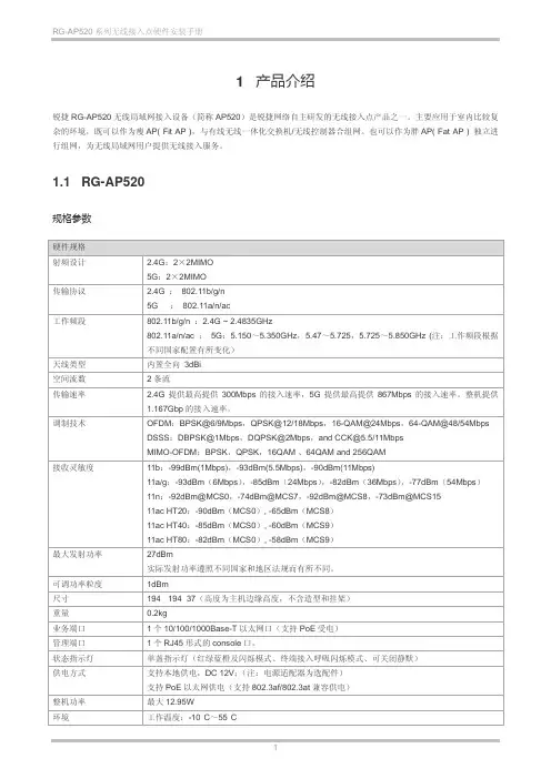
1 产品介绍锐捷RG-AP520无线局域网接入设备(简称AP520)是锐捷网络自主研发的无线接入点产品之一。
主要应用于室内比较复杂的环境,既可以作为瘦AP( Fit AP ),与有线无线一体化交换机/无线控制器合组网。
也可以作为胖AP( Fat AP ) 独立进行组网,为无线局域网用户提供无线接入服务。
1.1 RG-AP520规格参数硬件规格射频设计 2.4G:2×2MIMO5G:2×2MIMO传输协议 2.4G :802.11b/g/n5G :802.11a/n/ac工作频段802.11b/g/n :2.4G ~ 2.4835GHz802.11a/n/ac :5G:5.150~5.350GHz,5.47~5.725,5.725~5.850GHz (注:工作频段根据不同国家配置有所变化)天线类型内置全向3dBi空间流数2条流传输速率 2.4G提供最高提供300Mbps的接入速率,5G提供最高提供867Mbps的接入速率。
整机提供1.167Gbp的接入速率。
调制技术OFDM:BPSK@6/9Mbps,QPSK@12/18Mbps,16-QAM@24Mbps,64-QAM@48/54Mbps DSSS:DBPSK@1Mbps,DQPSK@2Mbps,and CCK@5.5/11MbpsMIMO-OFDM:BPSK,QPSK,16QAM 、64QAM and 256QAM接收灵敏度11b:-99dBm(1Mbps),-93dBm(5.5Mbps),-90dBm(11Mbps)11a/g:-93dBm(6Mbps),-85dBm(24Mbps),-82dBm(36Mbps),-77dBm(54Mbps)11n:-92dBm@MCS0,-74dBm@MCS7,-92dBm@MCS8,-73dBm@MCS1511ac HT20:-90dBm(MCS0), -65dBm(MCS8)11ac HT40:-85dBm(MCS0), -60dBm(MCS9)11ac HT80:-82dBm(MCS0), -58dBm(MCS9)最大发射功率27dBm实际发射功率遵照不同国家和地区法规而有所不同。
理想家庭车力帆520
佚名
【期刊名称】《《当代汽车》》
【年(卷),期】2009(000)001
【摘要】从未有轿车生产经验的摩托车巨人力帆集团,在2006年加入轿车制造的行列。
“力帆520”的命名很有意思,是“力帆我爱你”的谐音,不过两年多的时间里,随着520i、620,以及即将上市的320,力帆已经把X20作为了新车的系列命名方式。
【总页数】2页(P68-69)
【正文语种】中文
【相关文献】
1.信KP靠品牌以简代繁做力帆——记安徽六安市裕安区力帆车业经营部总经理张文兵 [J], 陶冶
2.两条腿走路,打造世界的力帆车——访重庆力帆实业(集团)公司常务副总裁关锋金[J], 刘玉健;
3.理想家庭车力帆520 [J], 徐钢
4.信KP靠品牌以简代繁做力帆记安徽六安市裕安区力帆车业经营部总经理张文兵[J], 陶冶
5.LIFAN 520ACS——换挡的革命·试驾力帆520ACS自动离合器版 [J], 张亮;林浩(摄影)
因版权原因,仅展示原文概要,查看原文内容请购买。
256MB XFX FX5200显卡产品综合性能获得提升佚名【期刊名称】《电脑采购》【年(卷),期】2003(000)033【摘要】<正> 目前的电脑游戏越做越好,越做越复杂,同时对硬件的配置要求也越来越高,这其中最关键的就是显卡,显卡的性能最直接影响游戏本身的质量和画面效果。
XFX显卡GeForceFX5200顺应时代潮流,为低端层次的玩家及用户推出了256MB显存版本产品,玩家可以更好的运行大型游戏和充分领略高容量显存带来的享受。
此款XFX显卡采用的是0.15微米制程的GeForce FX 5200图形芯片,集成与FX 5600一样多的4条像素渲染管线,支持AGP 8X传输规范,完全最佳化DirectX 9.0,为新一代的交互式电脑游戏注入了新的动力,带来了实时的电影效果般的渲染质量。
显存容量高达256MB,显存位宽为128bit,显存频率为400MHz,显存带宽达6.4GB/s,完全符合标准配置。
整块板卡的设计非常大方,用料也非常考究,和先前上市的128MB版本XFX GeForceFX 5200显卡做工基本一致,采用XFX独特设计的银白色散热风扇以保证图形芯片工作时候的热量迅速散发,相较于FX 5800级别显卡夸张的散热装置而言瘦身了不少,且静音效果较好。
此款XFX显卡是当今显卡市场上首款支持256MB显存容量的FX5200显卡。
由于3D电脑游戏程序愈来愈【总页数】1页(P13-13)【正文语种】中文【中图分类】F426.6【相关文献】1.XFX首发256MB FX5200 [J],2.低端市场新贵 XFX 256MB 6200显卡 [J], ;3.大容量显存带来更高性能 XFX GeForce FX5200(256MB)显卡 [J], 唐达鹏;4.699元我们能买到什么?——XFX 256MB FX5200显卡火热上市 [J], ;5.XFX首次发布256MB版FX5200 [J],因版权原因,仅展示原文概要,查看原文内容请购买。
nRF52820芯片详细概述2020年3月19日,Nordic宣布推出其nRF52系列中的第六款产品,nRF52820蓝牙5.2系统级芯片(SoC)。
据Nordic官方介绍这款nRF52820器件是功耗超低的低功耗蓝牙、蓝牙mesh、Thread、Zigbee和2.4GHz专有低端无线连接解决方案。
nRF52820具有蓝牙5、5.1和5.2的全部功能,包括长距离传输和2Mbps高吞吐量、寻向、低功耗功率控制和低功耗同步通道。
该器件还包括一个全速(12Mbps)USB2.0接口。
下面就随着蓝牙模块厂家云里物里科技一起来看下nRF52820芯片的性能概述。
nRF52820具有功能强大的64MHz32位Arm®Cortex®-M4处理器,并具有256KB Flash和32KB RAM,这使其成为范围广泛的商业和工业无线应用的理想的单芯片器件选择,包括专业照明、资产跟踪、HID和游戏产品。
此外,nRF52820具有功能齐全的多协议无线电和+8dBm输出功率,当与应用MCU配合使用时,它就成为网关和其他需要先进无线连接的智能家居应用的理想网络处理器。
nRF52820符合在-40至105°C扩展工业温度范围内的工作要求,适用于包括专业照明的商业和工业应用。
nRF52820的一项关键功能是全速(12Mbps)USB运作,USB是可与许多主机设备(例如PC、智能手机和网关)进行低延迟和高带宽通信的流行连接接口。
这种连接性还使得通过USB进行设备固件更新(DFU)变得切实可行。
除了主要的电源稳压器外,nRF52820的USB外还包括一个用于将5V VBUS信号转换为USB信令接口所需的3.3V信号的专用稳压器,从而省去了使用外部稳压器所需的成本和空间。
nRF52820包括多达18个GPIO和一系列模拟和数字接口,例如模拟比较器、SPI、UART、TWI 和QDEC。
电源电压涵盖1.7至5.5V输入电压范围,从而使得nRF52820可以使用纽扣电池和可充电电池供电。
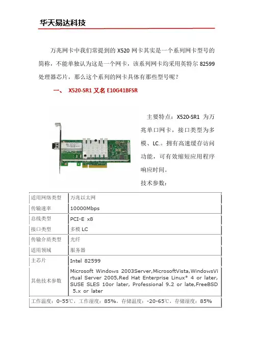
万兆网卡中我们常提到的X520网卡其实是一个系列网卡型号的简称,不能单独认为这是一个网卡,该系列网卡均采用英特尔82599处理器芯片,那么这个系列的网卡具体有那些型号呢?一、X520-SR1又名E10G41BFSR兆单口网卡,接口类型为多模、LC.。
拥有高速缓存访问功能,可有效缩短应用程序响应时间。
技术参数:二、X520-SR2 ( E10G42BFSR)主要特点:可轻松将任何PCI Array Express X8集成到万兆网络中。
并且对性能进行了优化,使系统I/O不再是高端网络应用的瓶颈,具有更强的可伸缩性,它带有两个完全集成的万以太网媒体存取控制(MAC)和SFP+端口,是部署多个网络以及在高性能服务器上部署关键网络应用环境的理想解网卡。
Intel E10G41BTDA/X520-DA1 网卡在模块配置上表现的灵活性更为突出,既可以配置单模的网卡模块,也可配置多模的万兆网卡模块。
技术参数:主要特点:2个SFP+插光纤、LR光纤,或直接连接电缆连网。
支持链接的英特尔VT,即虚拟机设备列队(VMDq)。
过虚拟化,LAN和SAN网络的灵活性,性能可靠技术参数:的存储环境中具有较强的灵活性和可伸缩性。
单个万兆端口,并配有一个单模模块,支持10公里范围内的远距离传输,能够显著提高网络性能!技术参数:主要特点:在虚拟和统一Array的存储环境中具有较强的灵活性和可伸缩性。
拥有两个万兆端口,并配有两个英特尔单模模块,模块支持双速率,既可以跑千兆也可以跑万兆(只建议用Intel原厂模块)支持10公里范围内的远距离传输,能够显著提高网络性能!技术参数:Intel X520系列网卡为以上六款,经常被运用在服务器、高端计算机网络项目中,可根据插槽灵活的选择合适的单、双口万兆X520网卡。
更多参数或报价信息可咨询intel分销中心华天易达。
低端显卡的DirectX 9领跑者——GeForceFX 5200横向评
测
blade
【期刊名称】《大众硬件》
【年(卷),期】2003(000)006
【摘要】虽然NVIDIA早就发布了全面支持DirectX 9的NV30,但599美元的价格并不是绝大多数用户所能接受的,毕竟中低端市场才是主流消费市场。
NVIDIA也深深认识到了这点,为了完善自己的产品线,也为了在中低端市场能有更好的表现,NVIDIS于3月14日正式发布了面向中端市场的GeForceFX 5600/Ultra(NV31)和面向低端市场的GeForceFX 5200/Ultra(NV34)。
【总页数】7页(P58-64)
【作者】blade
【作者单位】无
【正文语种】中文
【中图分类】TP334.7
【相关文献】
1.DirectX9下的终极较量——13款主流显卡横向评测 [J],
2.经济的低端之选——QDI夸父GeForceFX 5200显卡评测 [J],
3.走入低端显卡HDTV时代——市售12款X1300/Pro显卡横向评测 [J], QQ 糖
4.DirectX 9普及时代来临Force FX5200显卡横向评测 [J],
5.主流GeForceFX5500显卡横向评测 [J],
因版权原因,仅展示原文概要,查看原文内容请购买。
英特尔万兆双⼝⽹卡X520-SR2英特尔X520-SR2(E10G42BFSR)是⼀款万兆光纤双⼝⽹卡,采⽤Intel 82599芯⽚组,可优化CPU使⽤率,在多处理器系统中提⾼性能,有效地平衡⽹络负载,降低系统等待时间并提⾼I/O吞吐量,是新⼀代⾏业先进节能设计的多核处理器。
在万兆⽹络环境中,它的带宽可保证万兆位以太⽹连接中每个端⼝的优先性能,可实现多万兆位扩充性并延长正常运⾏时间。
主要参数适⽤⽹络类型万兆以太⽹传输速率 10000Mbps总线类型PCI-E X8接⼝类型 LC*2传输介质类型光纤适⽤领域服务器主芯⽚Intel 82599英特尔X520-SR2兼容操作系统MicrosoftWindows 2003Server,MicrosoftVista,Windows,Virtual Server 2005,Red Hat Enterprise Linux* 4 or later,SUSE SLES 10,or later, Professional 9.2 or late,FreeBSD 5.x or later优势特点:1.兼容性强2.端⼝灵活:双端⼝服务器适配器相当于2张万兆单⼝⽹卡,实现端⼝扩展,可有效平衡多个 CPU 内核间的⽹络负载。
3.⽅便管理:⽀持智能安装,可以很好的实现安装,并且⽅便⽇后系统的管理,节约时间和技术成本。
4.先进的服务器特性:⽀持负载均衡、冗余、⽀持虚拟化、等操作,功能强⼤。
Intel X520-SR2万兆⽹卡设计⽤于服务器和⾼端设备,可轻松将任何PCI Express X8、X16集成到万兆⽹络中。
更多关于Intel 万兆⽹卡的信息可以联系intel⽹卡分销中⼼华天易达,为您提供更专业的⽹卡选购⽅案。
混合式步进电机(BYG系列)步进电机是一种将电脉冲信号转换成角位移的执行元件,可在宽广的范围内调速。
在负载能力范围内,其输出转角定位精度无积累误差,特别适合于开环数控系统。
混合式步进电机是一种兼有反应式和永磁式两种步进电机优点的新型电机,国外主流品种,国内也已大面积取代反应式步进电机成为市场热点。
五相及三相混合式步进电机因其分辨率小,精度高,低频无振荡,高频力矩大,而成为混合式步进电机中的佼佼者。
一、特点本公司自行研制的BYG系列混合式步进电机,结合国内外先进技术而设计,采用优质材料和精良工艺制造,实行严格的质量管理,在国内处于领先水平,可与国外同类电机媲美。
其显著特点是:1、采用优质冷轧高矽片,无机壳铆压,大大改善了磁性能;电机体积小,驱动电流和功耗小,力矩大,运行频率高,动态特性好,温升低。
本公司产品的静态及动态力矩较国内同类产品高出一档次。
2、有良好的内部阻尼特性,运行平稳,无明显低频振荡区。
3、造型美观,结构牢固,噪音低,可靠性高,使用寿命长。
4、品种齐全,系列完整,可满足各种使用场合。
正广泛应用于各类机床,切割机,轻工、印刷、包装、纺织、环保、医疗机械,航空航海设备,汽车,机器人,舞台灯光控制、广告设备,电脑绣花机等自动控制领域。
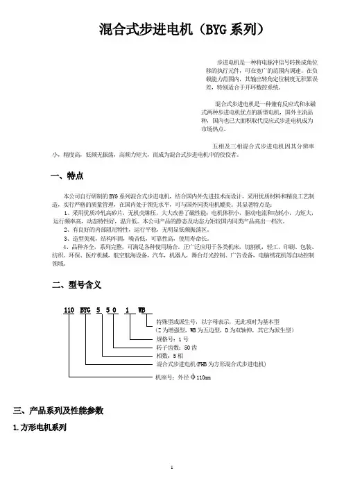
二、型号含义110 BYG 5 5 0 1 WB特殊型或派生号,以字母表示,无此项时为基本型(Z为增强型,WB为五边型,D为双轴伸,其它为派生型)规格号:1号转子齿数:50齿相数:5相混合式步进电机(FHB为方形混合式步进电机)机座号:外径φ110mm三、产品系列及性能参数1.方形电机系列2.圆形电机系列注:1、打 * 者为正在开发的新产品,可供期货;型号后有“Z”者为增强型。
2、二相电机为四引出线,四相电机为八引出线,除出线方式不同外,其余参数性能完全一样,配本公司驱动电源时用二相电机。
四相电机可改接成二相电机,有串联、并联及单极性三种接法,按并联接法时,相电流应加倍,四相电机用并联接法时,高速性能要优于其它接法。
vsx-520VSX-520是一款功能强大的音频设备,为用户带来卓越的音频体验。
以下是VSX-520主要的基本信息和功能特点:品牌: VSX型号: 520类型: 音频设备颜色: 黑色尺寸: XX cm x XX cm x XX cm重量: XX ___强大的功率输出,提供清晰而有力的音频效果。
支持多种音频格式,包括AAC、MP3、WMA等。
内置蓝牙功能,可与其他蓝牙设备无线连接,方便音频传输。
支持多个音频输入接口,如HDMI、光纤输入、RCA等,满足不同音频设备的连接需求。
支持音频输出接口,包括HDMI、光纤输出、RCA等,可连接至扬声器或其他音频设备。
配备了用户友好的操作界面,易于使用和设置。
提供多种音效模式选择,如音乐、电影、游戏等,以适应不同场景和需求。
具有智能省电功能,节能环保。
这些是VSX-520的一些主要特点,无论是在家庭娱乐中还是专业音频设备中,它都能为用户带来出色的音频体验。
功放功率:VSX-520具有强大的功放功率,能够提供清晰、动感的音频表现。
多媒体功能:VSX-520支持多媒体功能,可以播放各种音频和视频格式,满足用户的多样化需求。
功能丰富:VSX-520拥有多种功能,如音效调节、音场模式、音频解码等,使用户能够根据个人喜好进行调节和优化。
连接方式灵活:VSX-520支持多种连接方式,如HDMI、光纤、模拟音频等,可以与各种设备进行连接和配对。
用户友好:VSX-520的界面和操作简单易懂,用户可以轻松掌握设备的使用方法和功能。
耳机输出:VSX-520具有耳机输出接口,方便用户在不打扰他人的情况下享受音乐和影片的乐趣。
设计时尚:VSX-520采用时尚的外观设计,外壳材质优质,整体美观大方。
高音质:VSX-520通过先进的音频处理技术,能够提供高保真的音频效果,让用户享受纯净、逼真的音乐体验。
多种音效模式:VSX-520内置多种音场模式和音效调节选项,可以根据不同音乐类型和观影需求进行调整,带来沉浸式的音乐和影音体验。
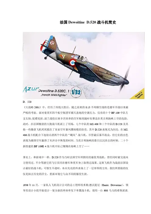
法国Dewoitine D.520战斗机简史D.520《大战略2001》中,经历了西线大胜后,随之而来的8.13不列颠空战将是德军开战以来最严峻的考验。
面对着英军四个航空集团军铺天盖地的空袭压力,仅有的十个BF-109中队左支右拙,捉襟见肘,波兰战役以来辛苦培养的空军精英随时有葬送在英吉利海峡上空的危险。
此时,在法国缴获的大批战斗机派上了用场,七个中队的MS.406和三个中队的D.520及其他一些缴获飞机死死抵住了皇家空军暴风骤雨般的狂攻。
其中D.520表现尤为闪亮,在MS. 406战斗机配合下连续击溃两个中队的“飓风”战斗机。
尽管最后寡不敌众,但它们的出色表现为德国空军赢得了从冲击中恢复的时间。
当英吉利海峡的暮日沉沉西去的时候,二十个新组建的BF-109E-4战斗机中队已翱翔在海峡上空了……事实上,和游戏中一样,D.520作为当时法国空军所拥有的最优秀战机,曾经同时被交战双方使用过,不少驾驶它的飞行员同在德军和英军身上取得过战果。
这架飞机作为战前法国设计最好的战斗机,可惜生不逢时,本应光亮的外表染上了一层厚厚的尘埃。
我们所要做的仅仅是抹去历史的浮尘,重新审视它与众不同的服役生涯。
1936年11月,一家私人飞机设计公司的总工程师埃米勒.德沃提尼(Emile. Dewoitine),领导其设计小组开始设计一架全新的单座单发下单翼战斗机,使用一台900马力的希斯派诺.絮扎V型12缸液冷发动机,设计速度为323英里/小时(520公里/小时)。
主要目的是为了竟标法国空军计划于1937年开始筹备的新一代战斗机。
很明显德沃提尼对这个最高时速相当自豪,因此新飞机被赋予“Dewoitine.520”的编号。
新飞机的设计冗余度相当大,可以换装希斯派诺.絮扎的1200马力液冷发动机。
晚些时候,德沃提尼的设计公司被国营南方航空制造厂(SNCAM)兼并,他本人也随后被任命为该厂的主管。
首批的三架原型机(编号D.520-01)于1938年10月2日于法国的土鲁斯试飞成功,试飞员为Marcel Doret。
FV520B是什么钢?
是什么钢?有没有国家标准?
FV520B是什么钢?
上海⾼⾼:FV520B是马⽒体沉淀硬化不锈钢,主要做风⼒系统叶轮叶⽚,也做坚挺螺旋桨⽤钢。
FV520B主要特性具,强度⾼,耐磨,耐⾼温,耐腐蚀,韧性好等综合性能。
价格不算便宜,性能当属⾼⾼。
所以⽤量不算⼤当然产量就不会多。
上海宝⼭⾼⾼特钢,主要以不锈钢FV520B的期货销售为主,我们备有⼤⼩不⼀的电渣钢锭。
⽅便很快出品你需要规格的
FV520B现货。
上海宝⼭
美兰湖:************,135****7556微-- -
FV520B⽤于⼤功率的风机系统,做⾼强结构件叶轮或者叶⽚压缩机转⼦等使⽤。
叶⽚具有良好的空⽓动⼒学特性,效率⾼、强度好、刚度⼤。
前向叶轮⼀般都采⽤圆弧型叶⽚,后向叶轮中,⼤型风机多采⽤翼型叶⽚,对于除尘效率较低的燃煤锅炉引风机可采⽤圆弧型或者平板型叶⽚。
多采⽤FB520B.
1050固溶处理+850中间处理+470时效时FV520B钢的强度达到极⼤值=FV520B的热处理。
本钢材属于⾼强度低合⾦钢,由于钢铁特殊性,必须经过电渣⼯艺才是真正的FV520B.
FV520B外国的牌号,咱中国⽣产⼀样⾼⾼质量。
FV520B化学成分:
C: 0.04- 0.07,Cr :13~14.5,Ni: 5~6,Mo :1.3~1.8,Cu :1.3~1.8, Mn:_ 1,No 0.25~0.45. Si 5 0.7,S和P:0.03,。
ZEP520A光刻胶经过电于示硅域深度影展微纳米状态ZEP520A光刻胶是一种高分辨率光刻胶,经过电于示硅域深度影展微纳米状态能够实现微细加工和纳米结构制备。
本文将介绍ZEP520A光刻胶的特性及其在微纳米加工领域的应用。
ZEP520A光刻胶是一种聚合物溶液,主要成分是聚苯乙烯。
它具有低粘度、高分辨率和高对比度的特点,适用于高分辨率的光刻加工。
ZEP520A光刻胶溶液通过旋涂在基片表面,在光照的作用下发生聚合反应,形成一层均匀的光刻胶薄膜。
经过电子束或者紫外线光刻机的曝光,光刻胶会在受到光线照射的区域发生聚合反应或解聚反应,从而形成所需的微细结构。
在电于示硅域深度影展微纳米状态中,ZEP520A光刻胶起到了关键的作用。
通过在光刻胶表面施加适当的电压或电流,可以调节光刻胶的深度。
电于示硅域深度影展技术利用了光刻胶中的电导率,通过在光刻胶表面施加不同电压,可以选择性地改变光刻胶的聚合程度和抗溅射能力,从而实现准确的微纳米结构制备。
ZEP520A光刻胶经过电于示硅域深度影展微纳米状态在微纳加工中具有广泛的应用。
首先,它可以用于制备微细结构,如光子晶体、微透镜、微孔阵列等。
通过控制电压,可以精确地调节光刻胶的深度,从而制备出具有高度均匀性和精确尺寸的微细结构。
其次,ZEP520A光刻胶经过电于示硅域深度影展微纳米状态也可以应用于纳米加工领域。
纳米加工要求更高的分辨率和精度,ZEP520A光刻胶能够满足这一需求。
通过电于示硅域深度影展技术,可以制备出尺寸在纳米级别的纳米结构,如纳米线、纳米点等,用于纳米电子器件的制备和纳米传感器的开发。
此外,ZEP520A光刻胶经过电于示硅域深度影展微纳米状态还可以应用于光刻胶的修复和改善。
在光刻过程中,光刻胶可能会受到光照不均匀、掩膜不完整等因素的影响而出现缺陷。
通过电于示硅域深度影展微纳米状态,可以对缺陷部分进行修复,提高光刻胶的质量和加工的可靠性。
在实际应用中,ZEP520A光刻胶经过电于示硅域深度影展微纳米状态需要严格的操作和控制。
雷豹加持火力全开:华硕TUF,GAMING,B550M-PLUS重炮手CFHD定制版主板测评华硕TUF GAMING B550M-PLUS重炮手CFHD定制版(以下简称TUF B550重炮手CFHD定制版)在彩盒包装方面与普通版有明显的区别,一改往日TUF GAMING电竞特工系列沉稳的军事迷彩风格,而是用上了《穿越火线》高清竞技大区CFHD(以下简称CFHD)独有的设计元素。
封面选用了CFHD中的人气角色形象雷豹,其设定形象背景为一支实力强大的秘密编制佣兵部队,哪里有战斗,哪里就会出现雷豹的身影,任何与之为敌的人都会胆寒。
雷豹的形象设计很符合TUF GAMING B550重炮手主板的定位,同时大量红色元素的应用,也符合AMD给玩家一贯的形象风格。
封面中雷豹手持一把默认皮肤的AK-47步枪,游戏中玩家们还可以为其换装为涂鸦__、黄金浇筑和黄金翼这个皮肤。
而“黄金AK47”则是CFHD众多玩家关注的焦点。
游戏中的AK47步枪威力巨大,但因为后坐力的关系也更需要玩家有着极好的操控能力。
这也和TUF B550重炮手的设计思路如出一辙,在玩家的调校下,TUF B550重炮手也能更好地释放处理器的极致性能,发挥最大威力。
TUF B550重炮手CFHD定制版采用了8+2 Dr.MOS供电模组,同时还搭载了通过军规认证的TUF电感和TUF电容,拥有更好的高温耐受性,有效地延长使用寿命和提升系统稳定性。
主板搭载了两条PCIe×16规格的插槽,能够很好地满足玩家们的扩展需要。
板载两个M.2插槽,主插槽直连处理器,通道上使用PCIe4.0×4,支持64Gb/s的NVMe M.2 SSD,能够为玩家提供更强劲的存储速度。
网络方面,TUF B550重炮手CFHD定制版主板搭载了2.5Gb有线网卡,拥有更高的网络传输速度和更低的网络延迟表现。
音频方面,该主板采用华硕和Realtek共同研发的S1200A 芯片,还搭载了全新的AI麦克风降噪技术,能够利用大数据库深度学习,在消除环境噪声的同时还保留玩家的声音,支持3.5mm音频插孔、USB或蓝牙等任何类型的耳机或麦克风,非常适合在录音、视频、直播和游戏等方面对语音通话质量有高需求的玩家。
ISOFLEX TOPAS NB 52, NB 152 , Prod. 004131, 004145, 081326, en Edition 29.01.2015 [replaces edition 15.10.2014]Benefits for your application–Longer component life when exposed to water or aqueous media due to special thickener –Many years of successful use in the automotive and machine building industriesDescriptionISOFLEX TOPAS NB 52 and ISOFLEX TOPAS NB 152 are rollingand plain bearing greases based on a synthetic hydrocarbon oiland a barium complex soap. The special barium-soap thickenerused in the ISOFLEX TOPAS NB 52 and 152 greases offers goodload-carrying capacity as well as resistance to water and ambientmedia unlike other soap-based thickeners. Both products showgood protection against corrosion as well as oxidation and ageingstability. The Klüber barium complex soap is ELINCS-registeredand approved by GASG (Global Automotive Stakeholders Group).ISOFLEX TOPAS NB 152 can be used in a wide servicetemperature range from -40 °C to 150 °C. ISOFLEX TOPAS NB52 is suitable for temperatures between -50 °C to 120 °C andshort peak temperatures up to 150 °C depending on theapplication, e.g. enclosed gears.ApplicationISOFLEX TOPAS NB 52 is a versatile grease for manyapplications, e.g.–rolling and plain bearings subject to high speeds and loads,also for low temperatures,–tooth flanks in precision gears, e.g. bevel gears in milling machines, electromechanical actuators for valves,–electric contacts and components to reduce insertion forces.In addition, ISOFLEX TOPAS NB 152 is compatible with many plastics.ISOFLEX TOPAS NB 152 is primarily used for rolling and plain bearings, for example wheel bearings in racing cars, fan bearings,pump bearings. The grease is also suitable for plastic/plastic or steel/plastic friction points.Application notes The greases are applied by spatula, brush, grease gun orcartridge. Sprays should not be exposed to direct sunlight andtemperatures above 50 °C.Material safety data sheetsMaterial safety data sheets can be requested via our website. You may also obtain them through yourcontact person at Klüber Lubrication.ISOFLEX TOPAS NB 52, NB 152Synthetic rolling and plain bearing greasesProduct informationProduct informationISOFLEX TOPAS NB 52, NB 152 Synthetic rolling and plain bearing greasesISOFLEX TOPAS NB 52, NB 152 , Prod. 004131, 004145, 081326, enEdition 29.01.2015 [replaces edition 15.10.2014]Klüber Lubrication – your global specialist Innovative tribological solutions are our passion. Through personal contact and consultation, we help our customers to be successful worldwide, in all industries and markets. With our ambitious technical concepts and experienced, competent staff we have been fulfilling increasingly demanding requirements by manufacturing efficient high-performance lubricants for more than 80 years.Klüber Lubrication München SE & Co. KG /Geisenhausenerstraße 7 / 81379 München / Germany /phone +49 89 7876-0 / fax +49 89 7876-333.The data in this document is based on our general experience and knowledge at the time of publication and is intended to give information of possible applications to a reader with technical experience. It constitutes neither an assurance of product properties nor does it release the user from the obligation of performing preliminary field tests with the product selected for a specific application. All data are guide values which depend on the lubricant's composition, the intended use and the application method. The technical values of lubricants change depending on the mechanical, dynamical, chemical and thermal loads, time and pressure. These changes may affect the function of a component. We recommend contacting us to discuss your specific application. If possible we will be pleased to provide a sample for testing on request. Klüber products are continually improved. Therefore, Klüber Lubrication reserves the right to change all the technical data in this document at any time without notice.Publisher and Copyright: Klüber Lubrication München SE & Co. KG. Reprints, total or in part, are permitted only prior consultation with Klüber LubricationMünchen SE & Co. KG and if source is indicated and voucher copy is forwarded.a company of the Freudenberg GroupProduct information。