Remote_Control执行机构操作手册
- 格式:doc
- 大小:1.72 MB
- 文档页数:9
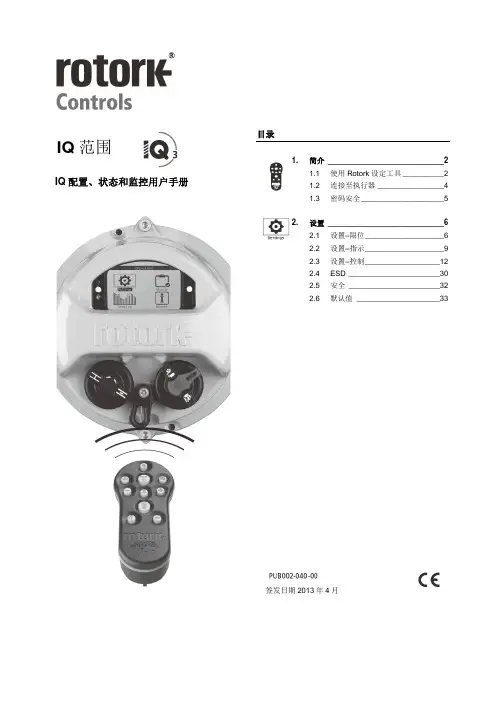
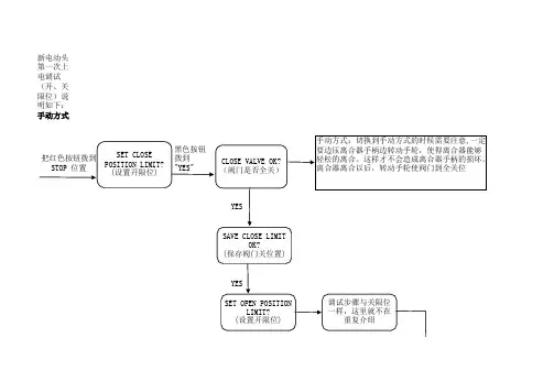
目录1.简介 ____________________________ 2 1.1 使用Rotork 设定工具 __________ 2 1.2 连接至执行器 ________________ 4 1.3 密码安全 ____________________ 52.设置 ____________________________ 6 2.1 设置–限位 ___________________ 6 2.2 设置–指示 ___________________ 9 2.3 设置–控制 __________________12 2.4 ESD ______________________302.5 安全 ______________________32 2.6 默认值 ____________________33IQ 范围IQ配置、状态和监控用户手册签发日期2013年4月2IQ3状态和监控–章节:简介1. 简介该手册提供了有关执行器设置和分析的说明。
我们重新组织了文件结构,将有关使用设置工具、按键导航和密码安全的说明包含于第1部分,当按照第2至第5部分中的要求进行设置和查看信息时必须应用第1部分中的这些说明。
因此,在继续进行前,用户必须熟悉第1部分中所含的操作。
应与执行器随附的PUB002-039,IQ系列安全使用、安装、基本设置及维护手册结合阅读。
1.1 使用Rotork设定工具设定器用于连接至执行器、浏览菜单、更改设置和查看执行器显示屏上所示的信息。
名称一般操作1. 键向上滚动。
2. 键向下滚动/连接3. 键减小数值/切换设置/向左滚动。
4. 键增大数值/切换设置/向右滚动。
5. 键选择加亮的项目。
保存加量的设置。
停止执行器运行(当设置工具控制启用时,参见第2.3.1部分)。
6. 键返回上一个菜单。
7. 键在数据记录器力矩图上的标准和缩放视图之间循环。
8. 键执行在Rotork蓝牙®设定器上存储的预设值操作。

电动执行机构 IQ 系列安装和维护手册出版物编号 E170C2出版日期 2002.3.请确保完整阅读和理解本手册Rotork设定器可按现场要求对执行器的控制、指示、保护功能进行设定。
所有的执行器在投入使用前,有必要检查其与过程控制系统要求的兼容性。
请阅读本手册。
当Rotork工作人员或指定代理商按照合同规定进行现场调试和验收时,执行器组态的相关文件应让客户留档备查。
本手册提供如下介绍:* 手动和电动(就地和远程)操作。
* 执行器的准备和安装。
* 根据有关阀门正确操作的要求,对执行器进行初级设定。
* 根据现场具体控制和指示的要求,对执行器进行二级设定。
* 维护 - 故障排除。
* 销售和服务。
RotorkIQ系列执行器- 全世界首家推出无需打开电气端盖即可进行调试和查询的阀门执行器。
使用所提供的红外线设定器进入执行器的设定程序,即使在危险区域,也可安全、快捷地对力矩值、限位以及其它所有控制和指示功能进行设定。
IQ的设定和调整在执行器主电源接通和断开时均可完成。
标准诊断功能可对控制系统、阀门和执行器的状态进行诊断,并通过执行器的显示屏上的图标和帮助屏幕来显示。
按一下设定器的按键即可在显示屏上对相应阀位的瞬时力矩进行监视。
内置的数据记录器可获取操作和阀门力矩数据,可提醒用户根据需要对阀门进行维护。
运行于PC机的IQ Insight软件和/或Rotork本安型通讯器可访问数据记录器,可对执行器的所有功能进行组态和记录。
执行器是否带有设定器,可根据接线端子箱盖上的黄色标签来识别。
有关Rotork IQ和其它系列执行器的资料,可浏览我们的网站 。
目录页码1 健康与安全 22 保存 33 IQ系列执行器的操作 3 3.1 手动操作 3 3.2 电动操作 3 3.3 执行器的显示- 4阀位指示3.4 执行器的显示- 5报警指示4 准备驱动轴套7 4.1 IQ7至IQ35 7A和Z型推力底座4.2 IQ7至IQ35 7B型非推力底座4.3 IQ40至IQ95 8A和Z型推力底座4.4 IQ40至IQ95 9B型非推力底座5 执行器的安装 105.1 提升杆式阀门- 11顶部安装5.2 带齿轮箱的阀门- 11侧面安装5.3 非提升杆式阀门- 11顶部安装5.4 手轮密封 115.5 IQM调节型执行器 125.6 IQML线性推力装置 125.7 IQML线性行程的调整 126 接线 146.1 地线的连接 146.2 端子箱盖的拆卸 146.3 电缆入口 146.4 端子的接线 156.5 端子箱盖的复位 157 设定 167.1 设定程序 167.2 设定器 177.3 进入设定程序 187.4 设定方式-口令 187.5 新口令 187.6 检查方式 187.7 程序路径分支- 19分支点 (Cr)7.8 执行器的显示 19设定 / 检查方式7.9 返回阀位指示 198 设定 - 初级设定功能 20初级设定功能目录 219 设定 - 二级设定功能 30二级设定功能目录 3010 维护和故障排除 6110.1 帮助显示 6310.2 IrDA诊断和组态 6811 重量和尺寸 70二进制、十六进制、十进制 71换算表本手册是为让用户能够胜任对Rotork IQ系列执行器的安装、操作、调试及检查而出版的。
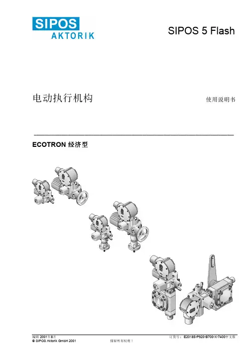
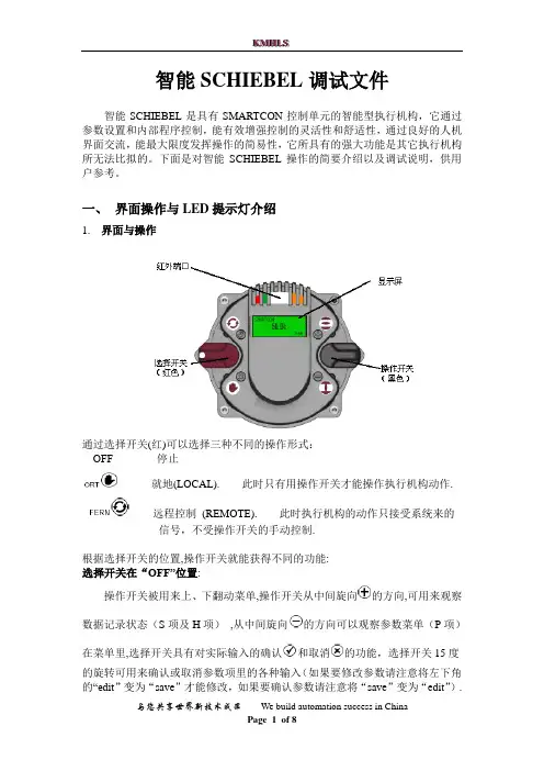
智能SCHIEBEL调试文件智能SCHIEBEL是具有SMARTCON控制单元的智能型执行机构,它通过参数设置和内部程序控制,能有效增强控制的灵活性和舒适性,通过良好的人机界面交流,能最大限度发挥操作的简易性,它所具有的强大功能是其它执行机构所无法比拟的。
下面是对智能SCHIEBEL操作的简要介绍以及调试说明,供用户参考。
一、界面操作与LED提示灯介绍1. 界面与操作通过选择开关(红)可以选择三种不同的操作形式:OFF 停止L就地(LOCAL). 此时只有用操作开关才能操作执行机构动作.远程控制(REMOTE). 此时执行机构的动作只接受系统来的信号,不受操作开关的手动控制.根据选择开关的位置,操作开关就能获得不同的功能:选择开关在“OFF”位置:操作开关被用来上、下翻动菜单,操作开关从中间旋向的方向,可用来观察数据记录状态(S项及H项),从中间旋向的方向可以观察参数菜单(P项)在菜单里,选择开关具有对实际输入的确认和取消的功能,选择开关15度的旋转可用来确认或取消参数项里的各种输入(如果要修改参数请注意将左下角的“edit”变为“save”才能修改,如果要确认参数请注意将“save”变为“edit”).如果在菜单中想快速返主界面,请将选择开关打到L位置即可。
选择开关在“REMOTE”位置这个状态是远程控制状态, 通过操作开关只可观察不同的数据记录,不能进行参数的设定选择开关在“LOCAL”位置操作开关被用来控制执行机构,既可以将开关置于机械保持位置使执行机构做持续运动,也可以通过小幅偏转使执行机构点动,.点动时操作开关都能通过弹簧回到中间位置2. LED 指示灯名称 颜色 亮闪烁 不亮 L1 红 开 正在开启 没到开位 L2 绿 关 正在关闭 没到关位 L3 黄 转矩正常 转矩故障---------------L4 黄就绪报警故障二、 调试说明调试是在确定机械安装和电气连接正确无误后方可进行!产品在出厂之前,参数都已按基本要求设置完成,请不要随意更改。
N17Q/ZTK 浙江罗托克执行器股份有限公司企业标准智能型电动执行机构用红外遥控调试器浙江罗托克执行器股份有限公司发布前言本标准按照GB/T 1.1-2020给出的规则编写。
本标准代替Q/ZTK 02-2018《智能型电动执行机构用红外遥控调试器》本标准与Q/ZTK 02-2018相比,主要变化如下:——企业名称由罗托克执行器有限公司变更为浙江罗托克执行器股份有限公司;——修改了5.3.1、5.3.2;──其他编辑性修改。
本标准可能涉及专利,本标准的发布机构不承担识别专利的责任。
本标准由浙江罗托克执行器股份有限公司提出。
本标准起草单位:浙江罗托克执行器股份有限公司。
本标准主要起草人:彭叔初。
本标准代替标准的历次版本发布情况:——Q/ZTK 02-2013、Q/ZTK 02-2014、Q/ZTK 02-2018。
智能型电动执行机构用红外遥控调试器1 范围本标准规定了智能型电动执行机构用红外遥控调试器的术语和定义、型式、要求、试验方法、检验规则、标志、使用说明书、包装、运输与贮存。
本标准适用于智能型电动执行机构用红外遥控调试器(以下简称红外遥控调试器)。
2 规范性引用文件下列文件对于本文件的应用是必不可少的。
凡是注日期的引用文件,仅注日期的版本适用于本文件。
凡是不注日期的引用文件,其最新版本(包括所有的修改单)适用于本文件。
GB/T 2829 周期检验计数抽样程序及表(适用于对过程稳定性的检验)GB 3836.1-2010爆炸性环境第1部分:设备通用要求GB 3836.4-2010爆炸性环境第4部分:由本质安全型“i”保护的设备GB/T 4208 外壳防护等级(IP代码)GB/T 9969 工业产品使用说明书总则GB/T 13384 机电产品包装通用技术条件GB/T 25480 仪器仪表运输、贮存基本环境条件及试验方法3 术语和定义下列术语和定义适用于本标准。
3.1红外遥控调试器 infrared remote control setting unit通过红外发射器件,发射编码脉冲信号调制的红外光,在一定距离控制相应设备实现相应功能的装置称为红外遥控调试器。
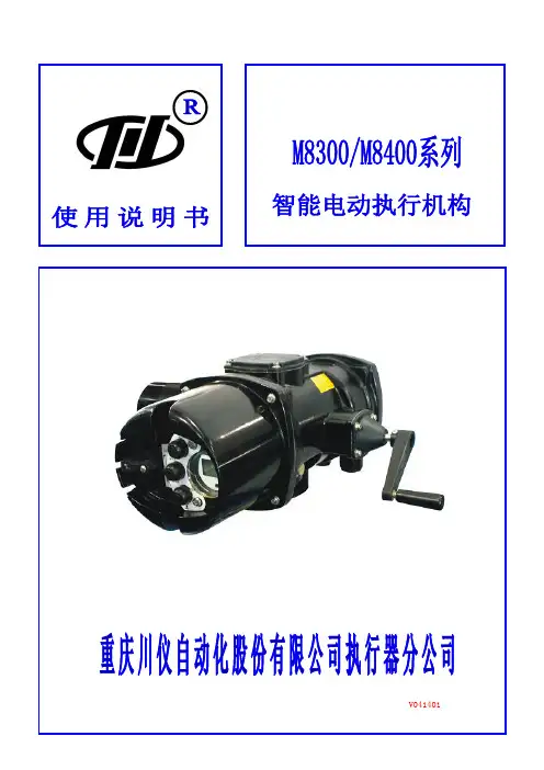
V041401前言感谢使用M8300/M8400系列电动执行机构,在安装调试之前请仔细阅读本说明书。
⏹关于本使用说明书(1)本使用说明书应交付给最终用户使用,敬请爱惜和妥善保存;(2)在开始操作前务请仔细阅读本使用说明书以充分理解操作该产品的方法;(3)未经许可,严禁摘录或复制本使用说明书的部分或全部内容;(4)本使用说明书的内容如有变动恕不事先通告;(5)在编写本使用说明书时已尽力确保其正确性,如用户发现有任何错误或遗漏,请与我厂市场部联系。
⏹安全使用注意事项(1)为了防护和确保本产品以及由本产品所控制的系统的安全,在产品的使用过程中必须严格按本使用说明书中与安全有关的说明和注意事项操作,否则一切后果自负,我厂概不负责。
(2)如果独立的防护装置或安全电路要安装与本产品或本产品所控制的系统,务请将这些电路装于本产品的外部,请勿试图对本产品进行改动或将这些电路装于本产品的内部;(3)当您更换产品的零部件或消耗品时,请采用我厂的推荐品。
⏹关于本产品的免责事宜(1)除了在另行提供的保证书中所提及的,我厂对于产品不做任何保证;(2)直接或非直接使用产品的过程中,因不可预见的产品缺陷对当事人造成的任何损失,我厂不承担赔偿责任。
⏹特别警示(1)执行机构最高处的油塞必须换成备件中提供的通气螺塞!(2)电缆线必须穿过备件中提供的出线套,并且旋紧!(3)出线罩的螺钉必须旋紧!强烈建议使用屏蔽导线连接!因未按本产品安装要求所造成的损失,本公司概不承担保修责任。
开箱检查、运输和贮存1 开箱检查每台执行机构在出厂之前,均经过严格检查,以确保产品的质量。
客户在执行机构拆箱后,请即刻进行下列检查:●检查执行机构是否在运输过程中造成损伤。
●检查执行机构机种型号是否与外箱印刷资料相同,实际装箱与装箱单是否一致。
2 运输与贮存●运输温度为-30℃~+75℃,贮存温度为-10℃~45℃。
●在无特殊包装的条件下,应放置在干燥的室内,避免冷凝的出现。
www.remotecontrol.seRemote Control LtdTel +44 (0)1889 57 6888Remote Control Sweden Tel +46 (0)23 587 00Remote ControlTel +49 (0)2131 7957 60Remote Control Asia Tel +65 6848 7150Remote Control Inc Tel +1 (0)401 294 1400GeneralThe MODE button selects a particular function, or mode, and the indicator for the selected mode turns on steady. Pushing the MODE button saves any new setting of the current mode before switching to the next mode. The adjust buttons up (▲) and down (▼) are used to make adjustments to current mode. For more details regarding calibration and features refer to the manual No. 621.1. Before applying power, ensure that the unit is properly mounted and properly wired to the actua- tor. Refer to the pertinent Data Sheet specifi ed for the actuator. Ensure potentiometer gears are tight and properly meshed.2. Apply power to the actuator on Connector J2: terminal #1 (neutral), terminal #2 (line) and termi- nal #3 (earth). There is no need for a signal con- nection during calibration.3. Push the MODE button until the yellow “MANUAL/ FB POT CAL” LED is illuminated. The LED may be fl ashing (at different speeds) through the next several steps. This is expected and will be explained.4. Use the adjust buttons (▲) and (▼) to move the actuator and verify that the limit switches are set past the desired open and closed positions; then move the actuator to mid stroke.5. If LED is solid, proceed to step 7.6. If LED is fl ashing, loosen the gear on the actuator shaft and rotate the potentiometer gear until the LED is no longer fl ashing, but on solid – this indi- cates the centre of the potentiometer’s travel. Note that the LED will fl ash at a slower rate the farther away from the mid position it gets. Once the LED is on solid tighten all gears.Top Quality Valve ActuatorsQuick Calibration Procedure DHC-100D7. Push the MODE button until the “CLOSE” LED is illuminated. Use the adjust buttons (▲) and (▼) to drive the actuator to the desired closed posi- tion. Ensure that the close limit switch does not engage.8. Push the MODE button until the “OPEN” LED is illuminated. Use the adjust buttons (▲) and (▼) to drive the actuator to the desired open position. Ensure that the open limit switch does not en- gage.9. If an OTR-100 option module is installed, follow Auxiliary Open/Close Setup (see page 2); other- wise continue to the next step.10. Push the MODE button until the “COMMAND TYPE” LED is illuminated. Use the adjustbuttons (▲) and (▼) to select appropriate input signal (4-20mA, 1-5VDC, 0-5VDC, 0-10VDCor Digital). If 0-5VDC or 0-10VDC is selected, the LOSS OF COMMAND features is not available, so proceed to step 12.11. Push the MODE button until the “LOSS OF COMMAND” LED is illuminated; this sets the actuator to a predetermined position upon loss of command. Use the adjust buttons (▲) and (▼) to select appropriate position (OPEN, CLOSE or LAST POSITION).InstructionDigital Controller PCU DHC-100DRCELRemote Control LtdTel +44 (0)1889 576 888Remote Control Sweden Tel +46 (0)23 587 00Remote ControlTel +49 (0)2131 795 760Remote Control Asia Tel +65 6848 7150Remote Control Inc Tel +1 (0)401 294 1400www.remotecontrol.se12. If an OTR-100 or OTX-100 option module is installed, follow Auxiliary Position Output Mode Setup (see below); otherwise continue to the next step.13. Push the MODE button until the “AUTO” LED is illuminated. Your calibration is nowCOMPLETE. Connect the command signal wires to connector J2: terminal #4 (signal ground) and terminal #5 (mA input) OR terminal #6 (volt- age input), depending on the application. If a signal input was already connected, the actuator should have moved to that position.Auxiliary Position Output Mode Setup (for units with an OTR-100 or OTX-100 option module only)Auxiliary open/Close Setup (for units with an OTR-100 option module only)1. Push the MODE button until the red “AUX POSI- TION OUT CAL” LED illuminates while the “CLOSE” LED fl ashes. Note that the red LED fl ashes to indicate a “Fault” and turns on steady to indicate the “AUX POSITION OUT CAL” modes.2. Use the adjust buttons (▲) and (▼) to set the desired output voltage or current (mA) on the option module output for closed position.1. Push the MODE button until the “AUX CLOSE OUTPUT” LED is illuminated. Use the adjust but- tons (▲) and (▼) to drive the actuator to the desired auxiliary close position.2. Push the MODE button until the “AUX OPEN OUTPUT” LED is on. Use the adjust buttons (▲) and (▼) to drive the actuator to the desired auxiliary open position.3. Continue with Step 10, page 1.3. Push the MODE button so the “AUX POSITION OUT CAL” LED remains steady while the “OPEN” LED fl ashes. Use the adjust buttons (▲) and (▼) to set the desired output voltage or current (mA) on the option module output for the open position.4. Continue with Step 13.Remote Control LtdTel +44 (0)1889 576 888Remote Control Sweden Tel +46 (0)23 587 00Remote ControlTel +49 (0)2131 795 760Remote Control Asia Tel +65 6848 7150Remote Control Inc Tel +1 (0)401 294 1400www.remotecontrol.seTroubleshooting GuideWe reserve the right to makechanges without noticewww.remotecontrol.seRemote Control LtdUnit 40, Trent Valley Works Station Road, Rugeley Staffordshire WS15 3HB EnglandRemote Control Sweden Box 80Kontrollvägen 15SE-791 22 Falun SwedenRemote Control Gutenbergstr. 22DE-41564 Kaarst-Büttgen GermanyTel +49 (0)2131 795 760Remote Control Asia No. 9, Kaki Bukit Road 1#03-03, Eunos Technolink Singapore 415938Tel +65 6848 7150Remote Control Inc PO Box 355386 Dry Bridge RdNorth Kingstown, RI 02852USAR e f N o 624 / Troubleshooting Guide。
华新水泥(阳新)有限公司MWFT培训教案:执行机构基本工作原理(二)——SIPOS 5电动执行机构授课人:卢荣俊西博思电动执行机构有限公司(原西门子公司电动执行机构部门)将先进成熟的电机变频调速技术应用于执行机构中,因内部集成了一体化变频智能控制单元,省去了其它执行机构必须的复杂电机转向控制箱,采用简单的模块化结构,通过增加少量必要的模块,使其适用于各种控制模式,可对阀门挡板进行可靠的开关控制和变频调节。
SIPOS5Flash PROFITRON变频智能型执行机构除具有其它执行机构的功能外,还具有一些特殊功能,即使阀门挡板被卡住,输出力矩也不会超过事先设定的上限,因为启动电流不会超过额定电流,可采用较细的电缆,自动校正供电电源相序,全面的电机保护功能,确保电机永远不会被烧毁,输出轴转速可自行设定。
采用超大规模集成电路器件替代机械零部件,电子器件没有磨损,无须维护,智能化程度高,且可以编程,其电子式限位保护功能和电子式过力矩保护功能取代了机械式限位开关和机械式力矩开关,这样省去了调试过程中费时的限位开关和力矩开关调整工作。
SIPOS5Flash PROFITRON变频智能型执行机构既可接受控制系统来的开、关、停和紧急4个开关量信号,也可以接受控制系统来的4~20mA.DC位置给定信号,也可以输出1路4~20mA.DC位置反馈信号和8个开关量的状态反馈信号,通过液晶显示屏,可以人机对话的方式进行参数设置,监控执行机构状态,进行故障自诊断。
一、变频器(VSD)内置一体化变频智能控制单元,远远优于电机加减速齿轮的设计方案,简化了机械结构,满足了执行机构控制阀门以精确的速度运行的过程要求,在不改变其内部机械结构的情况下,输出轴转速可在1:8的范围内自行设定。
1、整流限流和滤波经过整流后的电压首先经过直流母线上的大电容器CZK进行滤波,串联在回路中的限流电阻RV确保主回路电压在接通瞬间的跳跃变化不会立即传递给滤波电容器,在主回路电压接通并进入正常工作状态后,限流电阻由一继电器短路。
Using the Remote TransmitterLock or unlock the doors, tailgate and fuel-fill door. Start and stop the engine*.Built-in key*if equippedLeaving the key or remote transmitter in the vehicle can result in theft or accidental movement of the vehicle. Always take it with you whenever you leave the vehicle unattended.NOTICESmart Entry System*When you carry the remote transmitter (for example, in a pocket or purse)n Unlocking/Locking the DoorsTo unlock: With the vehicle off, grab the driver’s door handle to unlock the driver’s door. Grab the front passenger or rear door handle to unlock all doors and the tailgate.Door Lock ButtonButton*if equippedUnlocking/Locking the TailgateTo unlock: Press and hold the tailgate outer handle (under the tailgate TailgateHandleOuter Lock ButtonDoor OperationUse several methods to lock or unlock the doors.n Using the Lock TabTo unlock: When you unlock a front door using the lock tab, only that door unlocks.To lock: When you lock the driver’s door using the lock tab, all the doors and tailgate lock at the same time.n Using the Master Door LockSwitchTo unlock: Press the unlock side of the switch to unlock all doors and the tailgate.To lock: Press the lock side of the switch to lock all doors and the tailgate.To UnlockLock TabTo LockTo UnlockLock SwitchMaster Door To Lockn Childproof Door LocksThe childproof door locks prevent the rear doors from being opened from the inside, regardless of the position of the lock tab.Slide the lever in the rear door to the lock position and close the door.Open the door using the outer door handle.LockUnlockn Customizing Door Lock/Unlock SettingsCustomize the auto door-lock setting to your preference. Begin with the vehicle off.Models with color audioBegin with the vehicle stopped and the power mode set to e the p / q buttons to make selections, then press Enter.1.Press Home on the steering wheel.2.Select Settings.3.Select Vehicle Customization.4.Select Door/Window Setup.5.Select Auto Door Lock or Auto Door Unlock6.Select an option.àThe default for Auto Door Lock is With Vehicle Speed.àThe default for Auto Door Unlock is All Doors When Driver’s Door Opens.Goes back to the previous ENTER screen.Goes to home Enters the selected item.Outer HandleInner HandleCloseOpenn Power Sliding Doors*When the power mode is VEHICLEOFF (LOCK) or the remote engine start mode is active, the power slidingdoors operate when:•The power sliding door switch is ON (as shown) and•The power sliding door isunlocked and•The fuel-fill door is closed (fordriver’s side sliding door).OFF ONWhen the power mode is ON, the power sliding doors operate when:•The shift position is P and••*if equipped From the insidePress CLOSE to close the door.While a power sliding door is in operation, you can pull the handle again ton Walk Away Auto Lock*When you walk away from the vehicle while carrying the remote transmitter,the doors can automatically lock if the following conditions are met:•The remote transmitter is within a range of about 8 feet (2.5 m).•All doors are closed.•There is not an additional remote transmitter inside the vehicle.Follow these steps (see diagram):1.Carry the remote transmitter while you exit the vehicle. Stay near the vehicle until all the doors are all closed. Listen for a beep. The system is activated.2.Walk at least 5 feet (1.5 m) away.Listen for a beep and look for the lights to flash.The doors lock.To turn on this feature, follow the steps below:1.From the HOME screen, select Settings.2.Select Vehicle. The vehicle must be in Park (P).3.Select Keyless Access Setup.4.Select Walk Away Auto Lock.5.Select Enable.6.Select BACK to exit each menu.*if equippedPower Tailgate Operation*Use these methods to operate the power tailgate.n Power Tailgate Button The vehicle must be in Park (P) with all doors unlocked.Press and hold the power tailgate button on the dashboard until the tailgate starts to open. Press itagain to stop, or press and hold until it reverses.n Power Tailgate Inner ButtonPress the tailgate inner button to automatically close the tailgate.Press it again at any time to stop it.Press again to reverse the tailgate direction.Power Tailgate ButtonTailgate Inner Buttonn Manual OpeningPress and hold the tailgate outer handle longer than one second.The tailgate unlatches and you can open it manually.Outer HandleDo not push or pull on the power tailgate when it is being automatically opened or closed. Forcibly opening or closing the power tailgate while in operation can deform the tailgate frame.NOTICE。
©2007 Magnum Energy Inc. 1Part Number: 64-0016This ME-RB Owner’s Manual provides information on the ME-RB basic remote control and is a supplement to the ME-RC Owner’s Manual (Part Number: 64-0003).The information in this guide pertains to the ME-RB with revision 8.4 or higher; press the TECH pushbutton and view the 02 Revisions display for information on your remote’s revision level.ME-RB Basic Remote ControlThe ME-RB is Magnum Energy’s basic remote control. It operates very similar to the ME-RC, but is speci fi cally developed for OEM’s to allow only the basic operations of the Magnum Energy inverter/charger to be adjusted.Info: For information on installing, operating and troubleshooting the ME-RB, refer to these sections in the ME-RC Owner’s Manual.Differences between the ME-RB and ME-RCThe ME-RB remote is installed and operates identically to the ME-RC except for the following changes:The ME-RB does not include the AGS and METER pushbuttons. The AGS and METER pushbuttons are required to control and monitor the ME-AGS Auto Generator Start controller and ME-BMK Battery Monitor .The ME-RB does not include the Power Saver™ feature. The display backlighting and status LED’s always remain on.The SETUP menu in the ME-RB only provides menu items required for basic OEM inverter/charger system con fi guration.•••Magnum Energy Inc.1111 80th Street SW, Suite 250Everett, WA, USA Figure 1, ME-RB Remote Control2©2007 Magnum Energy Inc.ME-RB SETUP Menu:Info: For information on navigating the remote control, see the ME-RC Owner’s Manual (PN: 64-0003).Info: See fi gure 3, ME-RB Menu Map for a complete map of the menu items and adjustable settings available for the ME-RB remote control.SETUP: 01 Search Watts - Allows you to turn off the Search Watts feature or adjust the power level to determine when the search watts feature becomes active. The power level range selection is 5W to 50W . If this feature is not needed, select Search=Off . When search is turned off, the inverter continuously provides full AC voltage to the loads. For more information on this setting, see the SETUP: 01 Search Watts section in the ME-RC Owner’s Manual.Default setting: Search= 5WSETUP: 02 Batt AmpHrs - Used to select the approximate capacity of the battery bank connected to the inverter . This setting determines the time the battery charger is in the Absorb Charging stage (i.e. Absorption Time). Selections are in 200 AmpHrs increments from 200 - 1600 AmpHrs. For more information on this setting and to correlate the battery capacity to the Absorption Time; see the SETUP: 03 Batt AmpHrs section in the ME-RC Owner’s Manual.Default setting: Batt AmpHrs= 400SETUP: 03 Battery Type - Used to select the battery type, which determines the battery charge pro fi le and ensures the batteries are receiving the proper charge voltage. Selections are GEL (for Gel batteries), Flooded (for liquid lead acid batteries), AGM 1 (for Lifeline AGM batteries) and AGM 2 (for East Penn/Deka/Discover/Trojan AGM batteries). For more information on this setting and to determine the charging voltage; see the SETUP: 04 Battery Type section in the ME-RC Owner’s Manual.Default setting: BattType = FloodedSETUP: 04 Scrn Contrast - Used to adjust the contrast of the LCD screen for the best looking display based on the current lighting conditions and viewing angle.Default setting: Contrast = 32••••Press the SELECTknob to “save” your desired setting Press SETUP©2007 Magnum Energy Inc.3Status...Remote: **Status...FETs: **C/**FStatus...Tfmer: **C/**F.......Status...Shore Max = 50AStatus...Shore Max = 30A Figure 3, ME-RB Menu Map ME-RB Menu MapThe following fi gure is a complete overview of the settings and info displays available in the ME-RB; this should help with menu navigation.Limited WarrantyMagnum Energy, Inc., warrants the ME-RB Remote Control to be free from defects in material and workmanship that result in product failure during normal usage, according to the following terms and conditions:1. The limited warranty for this product extends for a maximum of 24 months from the product’s original date of purchase or for the same period as the connected Magnum Energy inverter if the inverter and remote are newly installed at the same time; whichever is longer.2. The limited warranty extends to the original purchaser of the product and is not assignable or transferable to any subsequent purchaser.3. During the limited warranty period, Magnum Energy will repair, or replace at Magnum Energy’s option, any defective parts, or any parts that will not properly operate for their intended use with factory new or rebuilt replacement items if such repair or replacement is needed because of product malfunction or failure during normal usage. The limited warranty does not cover defects in appearance, cosmetic, decorative or structural parts or any non-operative parts. Magnum Energy’s limit of liability under the limited warranty shall be the actual cash value of the product at the time the original purchaser returns the product for repair, determined by the price paid by the original purchaser. Magnum Energy shall not be liable for any other losses or damages.4. Upon request from Magnum Energy, the original purchaser must prove the product’s original date of purchase by a dated bill of sale, itemized receipt.5. The original purchaser shall return the product prepaid to Magnum Energy in Everett, WA. After the completion of service under this limited warranty, Magnum Energy will return the product prepaid to the original purchaser via a Magnum-selected non-expedited surface freight within the contiguous United States and Canada; this excludes Alaska and Hawaii.6. If Magnum repairs or replaces a product, its warranty continues for the remaining portion of the original warranty period or 90 days from the date of the return shipment to the original purchaser, whichever is greater. All replaced products and parts removed from repaired products become the property of Magnum Energy.7. This limited warranty is voided if:• the product has been modifi ed without authorization,• the serial number has been altered or removed,• the product has been damaged through abuse, neglect, accident, high voltage or corrosion.• the product was not installed and operated according to the owner’s manual.BEFORE RETURNING ANY UNIT, CONTACT MAGNUM ENERGY FOR A RETURN MATERIAL AUTHORIZATION (RMA) NUMBER.4 ©2007 Magnum Energy Inc.。
OPERATION MANUAL BRC315D71BRC315D7Remote controller4PW64949-1 – 10.2010Operation manual1The English text is the original instruction. Other languages are translations of the original instructions. This appliance is not intended for use by persons, including children, with reduced physical, sensory or mental capabilities, or lack of experience and knowledge, unless they have been given supervision or instruction concerning use of the appliance by a person responsible for their safety.Children should be supervised to ensure that they do not play with the appliance.Warning-Never let the remote controller get wet, this may cause an electric shock or fire.-Never press the buttons of the remote controller with a hard, pointed object. The remote controller may be damaged.-Never inspect or service the remote controller yourself, ask a qualified service person to do this.Contents page1.Features and functions (1) and function of switches and icons (2)3.Description of the operation modes (3)4.Operation (3)5.Programming the ON/OFF timer (5)6.Maintenance (6)7.T roubleshooting (6)1.Features and functionsThe BRC315D7 is a remote controller that offers control over your installation.1BASIC REMOTE CONTROLLERThe basic remote controller functions are:•ON/OFF,•operation mode change-over,•temperature adjustment,•air volume adjustment,•air flow direction adjustment.BRC315D7Remote controller Operation manual THANK YOU FOR PURCHASING THISCONTROLLER. READ THE MANUALA TTENTIVEL Y BEFORE USING THEINST ALLA TION. AFTER READING THEMANUAL, STORE IT IN A SAFE PLACEFOR FUTURE USE.Before initial operation, contact your dealerto obtain all details concerning your airconditioning installation.Operation manual 2BRC315D7Remote controller 4PW64949-1 – 10.2010 and function of switches andicons (Refer to figure 1)1ON/OFF BUTTONPress the ON/OFF button to start or stop the system.2OPERA TION LAMPThe operation lamp lights up during operation or blinks if a malfunction occurs.3OPERAThese icons indicate the current operation mode (FAN, AUTOMA TIC, COOLING, HEA TING).4EXTERNAL CONTROL ICONThis icon indicates that another controller with higher priority is controlling or disabling your installation.5This icon indicates that the ON/OFF timer is enabled. 6Consult your installer.7SET TEMPERA TURE DISPLAYThis indicates the current set temperature of the installation.8SETTINGNot used, for service purposes only.9This icon indicates the air flow direction (only for installations with motorised air flow flaps).10NOT AVAILABLEis displayed whenever a non-installed option is addressed or a function is not available.When multiple indoor units are connected on the same remote controller, "" will only be shown if none of the connected units have this function.1112AIR FILTER CLEANING TIME ICONThis icon indicates the air filter must be cleaned. Refer to the manual of the indoor unit.13Not used, for service purposes only.1415TIME ADJUST BUTTONThese buttons are used to adjust the timer, when in programming mode, to adjust the programmed action time. Both buttons have an auto-repeat function.16TEMPERA TURE ADJUST BUTTONSThese buttons are used to adjust the current setpoint (16~32°C) (step = 1°C).17OPERA TION CHANGE BUTTONThis button can be used to select the operation mode of the installation (FAN, AUTOMA TIC, COOLING, HEA TING).This function is default not available. This function is activated when the jumper (J8) wire is cut off. See installation manual on how to cut off the jumper (J8).BRC315D7Remote controller4PW64949-1 – 10.2010Operation manual318FAN SPEED BUTTONThis button toggles between L (Low), H (High), HH (very High), 19This button enables to adjust the air flow direction.20This button confirms or cancels the ON/OFF timer.21AIR FILTER CLEANING TIME ICON RESET BUTTONThis button is used to reset the air filter cleaning time icon.3.Description of the operation modes1FAN ONL Y OPERA TIONIn this mode, air only circulates without heating or cooling. 2AUTOMA TIC OPERA TIONIn this mode, the controller will automatically switch between heating and cooling as required by the setpoint or limit temperature.3COOLING OPERA In this mode, cooling will be activated as required by the setpoint or limit temperature.Only for 2 pipe indoor units: if the water temperature is not in the cooling range, the icon will be blinking.4HEA TING OPERA TIONIn this mode, heating will be activated as required by the setpoint or limit temperature.Only for 2 pipe indoor units: if the water temperature is not in the heating range, the icon will be blinking.4. Operation Manual operationIn manual operation, the user decides about the settings of the installation. The last setting remains active until the user changes it.As the controller can be implemented for a wide variety of installations and features, it might occur that you select a function that is not available on your installation; if this is the case, the message will appear.Use the button to select the desired operation mode if the jumper J8 is cut off.1 FAN ONL Y OPERA TIONUser adjustable parameters:•fan speed, use thebutton,•2AUTOMA TIC OPERA TION User adjustable parameters:•setpoint temperature, use theandbuttons,•fan speed, use thebutton,•Operation manual4BRC315D7Remote controller 4PW64949-1 – 10.20103COOLING OPERA TION User adjustable parameters:•setpoint temperature, use theand buttons,•fan speed, use the button,•air flow direction adjust, use the 4HEA TING OPERA TION User adjustable parameters:•setpoint temperature, use theand buttons,•fan speed, use the button,•air flow direction adjust, use theON/OFF timer operationThe actions programmed in the ON/OFF timer will be executed automatically.The ON/OFF timer always executes the last command; this means the user can temporarily overrule the last executed programmed action. Referto "Manual operation" on page 3. The next programmed action (in the ON/OFF timer) will return control to the ON/OFF timer.T o set up the TIMER refer to chapter "5. Programming the ON/OFF timer" on page 5.What can the ON/OFF timer do?The concept of the ON/OFF timer is simple,straightforward though powerful. The ON/OFF timer can order 2 actions:What will the ON/OFF timer do?If enabled, the ON/OFF timer will execute the programmed actions.It will order the installation to:•switch off the installation (the ON timer remains enabled and reactivates theinstallation as programmed); the operationlamp will turn off,OR •switch on the installation (the OFF timerremains enabled and will switch the installation off as programmed); the operation lamp will turn on.What will the ON/OFF timer NOT do?The ON/OFF timer will not:•control fan speed,•control air flow direction,•change the operation mode,•change the setpoint.The parameters listed above can be set manually,without interfering with the ON/OFF timer.More sophisticated remote controllers are available.Consult your dealer for more information.ON/OFF timer is enabled when the icon is visible. The overrules the ON/OFF timer until the next programmed action.1switch off the installation (end of control)2switch on the installation at a scheduled timeBRC315D7Remote controller4PW64949-1 – 10.2010Operation manual55.Programming the ON/OFF timerHow to program the ON/OFF timer?1Select ON/OFF timer to programPress the ON/OFF timer button to select theON timer or OFF timer.The icon will be blinking until the programmingis finalized.2Choose the time for the timer.Press the time adjust button and set the time.Each time pushed will increase thetime with 1 hour.Each time pushed will decrease thetime with 1 hour.Maximum 72 hours can be selected.3Confirm the ON or OFF timer.will be indicated in hours.4Cancellation of the timercancel the programmed timer.How to program the OFF timer and the ON timer at the same time? Example:Stop operation after 3 hours, then start the operation again after 1 hour.Manner of programming:Setting OFF timer after 3 hours and ON timer after 4 hours.1Push the ON/OFF timer button until the OFF timer icon is blinking.2Push the time adjust button and select 3 hours. 3Push the timer program button. OFF timer is programmed after 3 hours.4Push the ON/OFF timer button until the ON timer icon is blinking.5Push the time adjust button and select 4 hours. 6Push the timer program button. ON timer is programmed after 4 hours.The settings are complete.NOTE The OFF timer has a higher priority then the ON timer in case the timers are bothprogrammed on the same time.If the action is finished, it needs to bereprogrammed in case it is needed again.Operation manual6BRC315D7Remote controller 4PW64949-1 – 10.2010The remaining hours are displayed after the settings are completed.6.MaintenanceThe remote controller does not need maintenance.Remove dirt with a soft damp cloth.7.TroubleshootingThe guidelines below might help to solve your problem. If you cannot remedy the problem, consult your installer.No readings on the remote controller (display blank)Check if the mains power is still applied to your installation.Only is displayedThis indicates that the installation has just been powered, please wait until disappears.I cannot enable the ON/OFF timer (the icon is displayed)The ON/OFF timer can not be enabled when a centralised control is connected.NOTEOnly use clear tapid water to moisten the cloth.OFF timer = 3 hours ON timer = 4 hoursStop operation after 3 hours 1 hour left until the operation startsAll settings are finishedN OTESN OTESN OTESZandvoordestraat 300, B-8400 Oostende, Belgium 4PW64949-1 10.2010C o p y r i g h t 2010 D a i k i n。
Remote Control执行机构Remote Control专业从事新型流体自动化控制设备及系统的生产与研究,集团已有40年生产历史,现有美国公司、德国公司、新加坡公司以及三十多个分支机构。
Remote Control控制仪表以高防护性能和高可靠性为品质基础,适合于严寒、高温、海岸、海上、腐蚀气等环境下工作,在不同地区国家,推行本地化研究与发展,实现高品质下,在各地区国家的适应性。
Remote Control控制阀业已在角行程控制阀领域,实现了在蒸汽、油品、燃料和化学物料流体的良好调节与完全切断的研究和广泛使用,工程遍及化工、石化、电力、钢铁、供热和污水处理等行业,在工业消防和易燃品安全保护的控制领域,作出了跨时代的进步与创新。
未来,我们不止是电动、气动的多种控制模式的开发,还要全面发展Remote Control电液动和气动多回转控制,来满足现代生产过程更高更广泛的需求。
向用户提供“先进的技术、可靠的质量、优质的服务,良好的信誉”是我们更高的追求。
瑞典RC(Remote Control)系列阀门执行机构RC(Remote Control)是瑞典一家专业从事阀门执行机构生产的著名厂商,是世界上第三大阀门执行机构生产商,迄今已有40多年的历史。
主要产品包括角行程电动、气动和液动阀门执行机构,广泛应用于电力、石化、冶金、造纸、造船、医药、食品、环保等行业。
通过其全球性的服务网络、代理商、配套商和经销商,该产品已应用到世界100多个国家和地区。
RCE系列90°角行程电动执行机构输出转矩:90~2500Nm 控制模式:开关和调节控制防护等级:IP67 防爆等级:Exd II B T4/EExd II B T4产品认证:ISO9001、ISO14001、CERCP系列90°角行程气动执行机构输出转矩:10~30000Nm 作用形式:单作用弹簧复位和双作用结构原理:拨叉式连接标准:符合ISO5211和NAMUR标准产品认证:ISO9001、ISO14001、CERC系列产品:紧凑型多转式电液联动电液型防腐防火多转式0-180°带手轮高转矩特殊型其他产品:手轮电磁阀定位器限位开关指示器RC产品特点:产品线全:能提供电动、气动和液动三类产品,可满足用户多方面需求。
专业性强:能提供防腐、防爆、高温、高转矩等产品和个性化的解决方案。
结构紧凑:体积小(比同类产品小10-30%)、重量轻、功能齐全、经济性好。
可靠性高:保质1-3年(电动为1年、气动为3年)。
性价比好:高端品牌,中端价位。
全球典型用户:美孚(英国)壳牌(荷兰)宝洁(英国) B P 化工(英国)艾克森(英国)阿肯(英国)维美德(芬兰)蒂森(德国)埃尔肯(挪威)英国钢铁(英国)一胜百(瑞典)辉瑞(美国)中国典型用户:燕山橡胶宝洁洗涤台山电厂内蒙热电石景山电厂合肥二热杨柳青热电燕山炼油燕山化二沧州炼油北京焦化沧井化工吉林化工宣钢动力宣钢炼钢恒丰纸业宝鸡烟厂深水集团成自六厂沧井化工RC系列90°角行程气动执行机构RC是瑞典一家专业从事阀门执行机构生产的著名厂商,是世界上第三大阀门执行机构生产商,迄今已有40多年的历史。
RC系列90°角行程气动执行机构分单作用弹簧复位和双作用两种。
它采用拨叉式结构原理,具有体积小、重量轻、调节特性好、可靠性高、寿命长等特点。
可与角行程阀门(如蝶阀、球阀、旋塞阀)和类似用途机构等配套使用,广泛应用于电力、石油、化工、冶金、造纸、造船、食品、医药、水处理等行业。
其输出转矩范围:10-30000Nm。
一、规格型号1)基本型号:(1)单作用基本型号RC 210-SR 220-SR 230-SR 240-SR 250-SR 260-SR 270-SR 280-SR输出4Bar 气开0°14 29 54 110 170 345 710 143050°22 44 83 170 260 530 1100 2220 90°32 63 120 240 380 770 1590 3190气体消耗(dm3)6Bar时顺时针 1.1 1.3 4.0 5.0 13 16 54 67 逆时针0.6 1.1 2.2 4.4 6.9 13.8 33 66行程时间(S)6Bar时顺时针<0.5 <0.3 <0.25 <1.0 <2.5 <2.5 <6.0 <5.0 逆时针<0.25 <0.25 <1.0 <1.0 <1.5 <2.0 <4.0 <5.0法兰ISO/DIN F05 F05 F07/F10 F10/F07 F10/F12 F12/F10 F14 F16/F12 重量(Kg) 1.2 1.6 3.5 4.9 9.4 12 32 452)说明:工作压力:Max.10Bar。
工作介质:干燥、清洁、无腐蚀的气体(如空气、惰性气体等)。
环境温度:-20~+80℃(特殊温度:高温+150℃,低温-40℃)。
特殊要求:高转矩(达30000Nm)、超高温、强腐蚀,请与我们联系。
3)选型指南:(具体选型请与我们联系)举例:气源压力为6Bar,所需转矩为80Nm(80×1.25=100 ,1.25为安全系数)。
型号:单作用:RCP50-SR(查表时以开向90°值为准)。
双作用:RCP30-DA(查表时以90°值为准)。
二.组成结构1)整体结构:双作用特性曲线单作用特性曲线2)主要特点:(1)结构紧凑,体积小(比齿轮齿条式小20-30%)、效率高、重量轻。
(2)轴承传递动力,摩擦小、可靠性高、寿命长。
(3)开/关位置时输出转矩增大而运行速度降低,调节特性好。
(4)标准连接,符合ISO5211/DIN3337和NAMUR标准。
3)工作原理:(1)单作用气开弹簧复位气开时,压缩气体自底部进入气缸中腔(如左图),压缩弹簧,推动活塞向端部移动(主轴逆时针方向旋转),气动执行器打开。
弹簧复位时,气体从底部排除(如右图),弹簧推动活塞向中部移动(主轴顺时针方向旋转),气动执行器关闭。
(2)双作用气开气关气开时,压缩气体自底部进入气缸端腔(如左图),推动活塞向中部移动(主轴逆时针方向旋转),气动执行器打开。
气关时,压缩气体自底部进入气缸中腔(如右图),推动活塞向端部移动(主轴顺时针方向旋转),气动执行器关闭。
4) 手轮的操作对于配了手轮的执行器,在执行远程控制或自动控制时,一定要将手轮置于AUTO位置,即透明指示杆里面轴的末端(黄颜色部分)应与指示杆表面黄色部分(在中间位置)相对应。
在进行手动操作时,最好切断气源或者卸掉气源,也使汽缸里活塞上下部分气压平衡,轻松操作手轮。
5)零部件清单:序号名称材质表面处理数量序号名称材质表面处理数量单双单双1 调整螺栓不锈钢镀锌- 1 22 弹簧端板铝- 1 -2 调整螺帽不锈钢镀锌- 1 23 外弹簧弹簧钢防腐处理 1 -3 O型圈腈- - 1 24 内弹簧弹簧钢防腐处理 1 -4 固定螺栓不锈钢镀锌8/16 8/16 25 弹簧室铝阳极氧化 1 -5 端盖铝阳极氧化- 1 26 预紧螺栓不锈钢镀锌 1 -6 O型圈腈- 2 2 27 指示器聚合物 1 17 缸体铝阳极氧化 1 1 28 O型圈腈- 1 -8 拨叉钢- 1 1 29 调整螺帽不锈钢镀锌 1 -9 支撑件POM/PTFE - 1 1 30 垫片铝阳极氧化 1 -10 活塞铝- 1 1 31 上卡环弹簧钢防腐处理 1 111 滚动销弹簧钢- 1 1 32 中垫片弹簧钢防腐处理 1 -12 O型圈腈- 1 1 33 上垫片聚合物- 1 114 导向环PTFE - 1 1 34 密封圈腈- 1 115 主轴不锈钢镀锌,铬 1 1 35 下支撑环聚合物- 1 116 上支撑环聚合物 1 1 36 底支撑环聚合物- 1 118 O型圈腈- 1 1 37 轴套聚合物- 1 119 中支撑环聚合物- 1 1 38 O型圈腈- 1 120 销钢- 1 1 39 下垫片聚合物- 1 121 销套钢- 1 1 40 下卡环弹簧钢防腐处理 1 1三、外形尺寸1)单作用:RC A B C E F G H J K M N 法兰P/P1 S/S1 T/T1 U V Y Z 210-SR 45 150 32 41 75 16 10 35.4 35.4 40 30 F05 50 M6 11 35 2 14 19 220-SR 150 150 32 41 75 16 10 80 30 - - F05 50 M6 11 35 2 14 19 230-SR 65 200 49 55 110 25 16 80 30 - - F07/10 70/102 M8/10 14/17 55 3 17 30 240-SR 200 200 49 55 110 25 16 80 30 - - F10/07 102/70 M10/8 17/14 70 3 22 30 250-SR 90 285 69 75 155 35 22 80 30 - - F10/12 102/125 M10/12 17/21 70 3 22 37 260-SR 285 285 69 75 155 35 22 80 30 - - F12/10 125/102 M12/10 21/17 85 3 27 37 270-SR 145 510 110 110 248 60 40 130 30 - - F14 140 M16 25 100 4 36 64 280-SR 510 510 110 110 248 60 40 130 30 - F16/12 165/125 M20/12 32/25 130 5 46 64(2)双作用:RC A B C E F G H J K M N 法兰P/P1 S/S1 T/T1 U U Y Z21045 98 32 41 75 16 10 35.4 35.4 40 30 F05 50 M6 11 35 2 14 19-DA。