LS30用户操作手册V2.0
- 格式:pdf
- 大小:3.10 MB
- 文档页数:66
min海康威视iVMS-9300综合监控与运维管理平台用户操作手册杭州海康威视系统技术有限公司2016.3目录目录 (1)第1章前言 (5)1.1编写目的 (5)1.2术语和缩写 (5)第2章平台概述 (6)2.1环境要求 (6)2.1.1运行硬件环境 (6)2.1.2运行软件环境 (6)2.2用户登录 (7)第3章运维概况 (7)3.1视频概况 (11)3.1.1视频概况 (11)3.1.2一键运维 (13)3.2卡口概况 (14)3.2.1过车统计 (15)3.2.2资源信息 (15)3.2.3服务器信息 (15)3.2.4最新异常信息 (16)第4章巡检中心 (16)4.1运行监测 (17)4.1.1监控点视频 (17)4.1.1.1 监控点明细查看 (17)4.1.1.2 视频预览 (18)4.1.1.3 工单上报 (19)4.1.1.4 视频质量诊断图片查看 (20)4.1.1.5 图像重巡 (21)4.1.1.6 查询导出 (21)4.1.2录像 (22)4.1.2.1 录像详情查看 (23)4.1.2.2 巡检一次 (24)4.1.2.3 工单上报 (24)4.1.2.4 查询导出 (25)4.1.3卡口 (26)4.1.3.1 卡口信息 (26)4.1.3.2 异常信息 (28)4.1.4编码资源 (29)4.1.4.1 设备详情查看 (30)4.1.4.2 工单上报 (31)4.1.4.3 查询导出 (31)4.1.5解码资源 (32)4.1.5.1 解码资源详情查看 (33)4.1.5.2 工单上报 (33)4.1.6视频服务 (35)4.1.6.1 服务详情查看 (35)4.1.6.2 工单上报 (36)4.1.6.3 查询导出 (37)4.1.7视频矩阵 (38)4.1.7.1 视频综合矩阵查看 (38)4.1.7.2 解码子系统 (39)4.1.7.3 编码子系统 (39)4.1.7.4 报警子系统 (39)4.1.7.5 码分子系统 (40)4.1.7.6 工单上报 (40)4.1.8智能机柜 (40)4.1.9业务树 (41)4.2可视监测 (42)4.2.1拓扑监测 (42)4.2.1.1 绘制拓扑图 (44)4.2.1.2 编辑栏介绍 (46)4.3告警查询 (47)4.3.1告警详情查看 (47)4.3.2解决告警 (48)4.3.3删除告警 (48)4.3.4创建工单 (49)4.3.5查询导出 (49)第5章资产管理 (50)5.1监控点资产 (50)5.2其他资产 (54)5.3资产统计 (57)第6章工单管理 (58)6.1待办工单 (58)6.1.1待审核 (59)6.1.1.1 查询导出 (60)6.1.1.2 工单处理 (60)6.1.1.3 工单驳回 (62)6.1.1.4 工单挂起 (65)6.1.2待反馈 (65)6.1.2.1 工单反馈 (66)6.1.2.2 查询导出 (67)6.1.3待确认 (67)6.1.3.1 维修审批 (68)6.1.3.2 延期审批 (69)6.1.3.3 查询导出 (69)6.2工单查询 (70)6.2.1综合查询 (70)6.2.2我创建的工单 (71)6.2.2.2 查询导出 (72)6.2.3已挂起工单 (73)6.2.1延期工单 (73)第7章统计报表 (74)7.1点位统计 (74)7.1.1监控点视频诊断统计 (74)7.1.2离线点位情况统计 (76)7.1.3历史离线时长统计 (76)7.1.4最近离线时长统计 (77)7.1.5区域运维考核统计 (77)7.1.6点位运行考核统计 (79)7.1.7经纬度考核统计 (79)7.2录像统计 (81)7.2.1区域录像情况统计 (81)7.2.2点位录像情况统计 (82)7.3工单统计 (82)7.3.1区域工单数量统计 (83)7.3.2人员工作数量统计 (83)7.3.3工单处理效率统计 (84)7.3.4工单处理及时统计 (84)7.4资产统计 (85)7.4.1区域资产数量统计 (85)第8章配置管理 (86)8.1巡检配置 (86)8.1.1采集器管理 (86)8.1.1.1 修改NMS采集器 (86)8.1.1.2 新增VQD采集器 (87)8.1.1.3 修改VQD采集器 (87)8.1.1.4 删除采集器 (87)8.1.2 NMS计划配置 (88)8.1.2.1 新增NMS采集计划 (88)8.1.2.2 修改NMS采集计划 (89)8.1.2.3 删除NMS采集计划 (89)8.1.2.4 启用采集计划 (90)8.1.2.5 禁用采集计划 (90)8.1.2.6 分配资源 (90)8.1.2.7 高级过滤 (91)8.1.3 VQD计划配置 (91)8.1.3.1 新增VQD采集计划 (91)8.1.3.2 修改VQD采集计划 (93)8.1.3.3 删除VQD采集计划 (93)8.1.3.4 启用采集计划 (94)8.1.3.5 禁用采集计划 (94)8.1.3.6 分配资源 (94)8.1.4告警阀值配置 (95)8.1.4.1 设备告警阀值配置 (95)8.1.4.2 编码设备和解码设备告警阀值配置 (95)8.1.4.3 监控点告警阀值配置 (96)8.1.4.4 视频综合平台和子系统告警阀值配置 (96)8.1.4.5 服务告警阀值配置 (97)8.1.5告警联动配置 (97)8.1.5.1 告警联动计划编辑 (98)8.1.5.2 查询 (99)8.1.6工单联动配置 (99)8.1.6.1 工单联动计划配置 (99)8.1.6.2 查询 (101)8.2资源配置 (101)8.2.1资源管理 (101)8.2.2组织树管理 (105)8.2.3业务树管理 (108)8.2.3.1 业务导航树 (108)8.2.3.2 资源列表 (110)8.3日志查询 (112)8.3.1操作日志 (112)8.3.2系统日志 (113)第9章系统配置 (114)9.1权限设置 (114)9.1.1用户管理 (114)9.1.1.1 同步单位信息 (114)9.1.1.2 同步用户信息 (114)9.1.1.3 批量设置角色 (115)9.1.1.4 批量取消角色 (116)9.1.2角色管理 (116)9.1.2.1 新增角色 (116)9.1.2.2 修改角色 (117)9.1.2.3 删除角色 (117)9.1.2.4 权限配置 (118)9.2基础设置 (118)9.2.1系统信息配置 (118)9.2.2字典管理 (119)9.2.2.1 新增字典 (119)9.2.2.2 修改字典 (119)9.2.3邮件配置 (120)9.2.4短信配置 (121)9.2.5密码强度扫描配置 (122)第1章前言1.1编写目的本用户手册的编写目的是帮助用户了解《iVMS9300综合监控与运维管理平台》,并学会对系统的操作。

酒店设置要进入酒店菜单,在TV源下顺序按静音-静音-菜单-静音-静音-菜单键进入酒店设置菜单(按键速度不要太快)。
注:如果中途发生按键错误,可先按除上述两键以外的任意键清除后,再按照正确的顺序输入即可。
※ 酒店模式(HOTEL模式)酒店模式设置为开,酒店菜单的其他功能才起作用。
此时设置菜单的频道选项为灰色(即调谐被锁定)、设置菜单的系统设置下复位项为灰色。
※ 开机源通过设置可统一酒店内部每一台电视机交流开机后进入的信号源,可在所有信号源之间选择。
如不需要设置开机源,则将该项置为“关”。
※ 开机频道:当开机源为TV时设置电视交流开机后进入的频道号。
※ 开机音量设置开机音量,可统一酒店内每台电视开机时的音量。
(选择范围:0—最大音量)※ 最大音量设置最大音量,可限制酒店内每台电视可调节的最大音量。
(选择范围:开机音量—100)※ 面板锁(KEYBOARDLOCK)开启此功能,电视机本机按键除主电源开关外都不起作用。
只能用遥控器进行操作。
※ 自动恢复(AUTORESUME):宾馆功能开之前设置原始数据,宾馆功能开后每次开机都恢复到原始数据。
※开机模式:可按实际需要设置为一次开机或二次开机※音乐频道:选中此项后,按音量+/-键选择所需节目号。
当用户使用中调到该节目号时,屏幕无图像显示且只播放声音。
※克隆模式(CLONE模式):选择电视机克隆数据发送(SEND)还是接收(RECEIVE)。
※克隆(CLONE):执行克隆,进入克隆模式。
(具体见克隆操作指南)※用户画面:选择电视开机时显示画面,设置为开则显示导入的开机画面。
※导入画面:执行导入画面功能。
(具体见导入画面操作指南)克隆操作指南1.没有母机和子机之分;2.所有机器必须是带USB克隆的宾馆软件状态;3.选择1台整机进行调试,将所有功能数据都调整到符合宾馆要求的状态(包括宾馆菜单中的设置),进行遥控关机再开机,确认所有数据都存储完成;4.插上U盘(注意必须是FA T32的文件格式),在TV下连续按“静音静音菜单静音静音菜单”进入宾馆菜单,可能会有1-3秒钟的等待时间;如果发现没有进入宾馆菜单,请按除了静音和菜单外的任意遥控键后,再重新进行操作;5.选择克隆模式为“发送”进行克隆,则将电视中的数据往U盘中拷贝,成功后在U盘根目录下有一个为“LS30_CLONE.BIN”的文件;6. 选择克隆模式为“接收”进行克隆,则将U盘中的数据往电视中拷贝,成功后请交流关机,再开机。

cascadecorporationCascade is a Registered Trademark of Cascade CorporationManual Number 6904573Hydraulic Force ControlCarton Clamp on Crown FC5200 TruckCONTENTSPageOVERVIEW1INSTALLATION2Prepare Attachment Valve2Equalizer Valve and Hoses3HFC Valve and Hoses4Return Line Adapter5Sensor Switches6Disabling HFC System7SETUP8OPERATION10TROUBLESHOOTING11PARTS14GLOSSARY21i6904573Cascade Corporation. Refer to the back cover.What The System DoesThe HFC system enables Cascade Carton Clamps to automatically apply clamp force proportional to theweight of the load. This system will reduce the chance of damage caused by excessive clamp force.How The System WorksAn initial no-slip starting pressure is applied to the load when it is first clamped. As the load is lifted, the HFC system increases clamp force and applies a consistent clamp force proportional to load weight. The hoist system provides pressure to the HFC to increase clamp pressure as hoist pressure increases.HOIST pressure should be equal to or higher than clamp pressure to properly clamp the load. Total weight equals load weight plus clamp weight.Confirm that the truck size is compatible with the clamp capacity. Available maximum hoist pressure with load weight (combined maximum size load and weight of the clamp) should be determined in freelift. The hoist pressure determined needs to be within 10% of the clamping pressure required to clamp the heaviest load.The following is provided to assist in planning hose and fitting sizes to match the lift truck hoist line:Equalizer Valve Fittings – The mast and truck ports are No. 12 O-ring. No. 12-10 Face Seal reducers are supplied to adapt to the truck hoist lines.269045732 Disconnect the hydraulic hoses from the valve CLAMP(CL), OPEN (OP) ports.3 Remove CL port special fitting with spool or orifice pipe plug.4 Install kit .25 in. dia. NPTF plug (Part No. 6603) into CLport and reinstall fitting leaving spool out.Front ViewG & J-Series Valves1 Install kit .3125 in. dia. setscrew (Part No. 5304) andpipe plug into OR port.INSTALLATION36904573AC3263.eps1 Install the equalizer valve in the hoist circuitbetween the hoist auxiliary valve and mast lowering control valve.2 Install the hose from the hoist auxiliary valveHOIST port to the equalizer valve TRUCK port. 3 Install the No. 10 hose (48 in.) that connects the MAST port of the equalizer valve to the mast lowering control valve.4 Inspect hoses for pinch points and secure asrequired.Mast CylindersEQUALIZER VALVE AND HOSES Equalizer ValveTo Mast Lowering Control Valve No. 10 Face Seal3INSTALLATION46904573AC3262.epsHFC VALVE AND HOSES1 Remove the capscrews fastening the loweringcontrol valve to the mast crossmember. Install the new bracket to the mast crossmember with the kit sockethead capscrews going through the valve. The short capscrews are used as jack screws to stiffen the bracket against crossmember.2 Install the HFC valve to the bracket.3 Connect a No. 6 (minimum) hose from the truck clamp auxiliary valve clamp port to the CL1 port on the bottom of the HFC valve.4 Connect a No. 6 (minimum) hose from the truck clamp auxiliary valve open port to the OP1 port on the bottom of the HFC valve.5 Connect the No.6 hose (16 in.) from theCL2 port on the HFC valve to the attachment CLAMP supply hose.6 Connect the No. 6 hose (14 in.) from the OP2 port of the HFC valve to the attachment OPEN supply hose.7 Connect the No. 4 hose (22.5 in.) from the H port on the bottom of the Sideshift Manifold to the HFC port on the equalizer valve.8 Connect the hoses from the truck sideshiftauxiliary valve ports to the SS IN ports on the bottom of the Sideshift Manifold.9 Connect the No. 6 (14 in. and 16 in.) hosesAttachment10INSTALLATION56904573RETURN LINE ADAPTER1 Install a return line adapter fitting in the tank line. Lubehose ends and fitting for easy assembly. For complete installation procedure, refer to Installation Instructions 211744.Attachment ValveAC0226.epsReturn-to-Tank 112NOTE: For trucks with pressurized return-to-tank lines, the hydraulic tank filler cap must be opened to relieve trapped pressure.2 Connect the T port on the bottom of the HFC Valve tothe truck tank line fitting.3 Connect the T port on the bottom of the HFC Valvesideshift manifold to the truck tank line using the tee fitting provided.4 Inspect hose for pinch points and secure as required.Single Line Adapter Kits Tank Hose ID Adapter Tee Length Kit Part No..75 in. (19 mm) *1.00 in. (25 mm) *1.25 in. (31 mm) * 4.12 in. (105 mm)4.12 in. (105 mm)4.12 in. (105 mm)6807816 6807816 6807816* Included in Kit 6807816AC3264.epsINSTALLATION66904573AC3155.epsSENSOR SWITCHES1 Determine locations to mount sensor switches Aand B on the mast. Sensor A is used to detect inner upright extension. Sensor B is used to detect when the carriage is positioned near full freelift. The sensor switches signal the mast transition from freelift tomainlift. The provided mounting brackets can be used or modified to aid with mounting the sensor switch. Install Sensor B to the side of the mast outer upright with the M4 buttonhead screws and washers provided. A drill and M4 tap is provided in the kit.CAUTION: Consult the LIft Truck OEM for proper + power source connection.2 Connect the harness solenoid connector to the solenoidcoil.3 Connect the harness sensor switch connectors to thesensor switches.4 Connect the harness cable ends to the componentsshown.24V–100V Systems – Connect the fused positive wire from the cable harness to a DC-to-DC converter positive output wire and the ground wire to the converternegative output wire. Connect a 24V–100V switched power source to the converter fused positive input wire and connect the converter input ground wire to a chassis ground.NOTE: For troubleshooting the wire harness, refer to page 11.SolenoidRelayGroundUpperCarriage BarSensor Switch B2 in. before MainliftUprightINSTALLATION76904573DISABLING HFC SYSTEMTo temporarily disable the HFC features, perform the following steps:1 Turn V1 in (CW) or until desired clamp pressure isreached. The maximum pressure that the cartridge is capable of handling is 3000 psi (207 bar).2 Turn V4 all the way out (CCW).3 OPTIONAL: If the hoist capacity is affected by lifting aload, turn V6 all the way out (CCW).4 Turn V8 all the way in (CW). Turn V7 all the way in (CW).5 The truck attachment will now operate in the standardmode.NOTE: To enable HFC features refer to Setup Section.HFC VALVEV586904573SETUPCARTRIDGE FUNCTION SUMMARYStarting Pressure (V1) – Sets starting pressure.Final Pressure (V2) – Adjusts clamping pressure after hoisting. Must be adjusted after all other cartridges are set.HFC Enable Pressure (V3) – Closes connection from hoist line to clamp line.Max. Clamp Pressure (V4) – Limits maximum clamping pressure. Must not be set lower than pressure needed to handle maximum load.Freelift Pressure (V5) – Increases freelift hoistingpressure. Balances freelift and mainlift hoisting pressure and make pressure available to clamping circuit.Hoist/Clamp Pressure (V6) – Increases clamp pressure when a load is hoisted. This should only be adjusted after all other cartridges (except V2) are set, if need. NOTE: This cartridge is fully turned out at the factory.Sideshift Pressure (V7) – Adjusts the available sideshift pressure.Backhand Pressure (V8) – Adjusts the maximum backhand pressure.HFC ENABLE PRESSUREMAXIMUM CLAMP PRESSURECARTRIDGE ADJUSTMENTAdjusts clamping pressure after hoisting. Adjust this cartridge last.Closes connection from hoist line to clamp line.Limit maximum clamping pressure.IMPORTANT: Check that V2 and V6 (on equalizer valve) is completely turned out (counterclockwise) before adjustment process.1 Install the pressure gauge (Cascade PressureTest Kit 6034612) in the clamp gauge port.2 Adjust the Starting Pressure (V1) cartridgeso that a light load is not damaged or over clamped and the heaviest load does not slip upon hoisting.NOTE: For attachments that are retrofitted from three position relief to HFC system and lowest pressure is known, use the lowest pressure as starting pressure.3 To prevent carriage/attachment from loweringduring arm closing, adjust the HFC Enable Pressure (V3) cartridge.• If the maximum weight load slips when hoisting, reduce V3 by turning counterclockwise (CCW).• If the carriage lowers when closing the arms of the clamp or light loads are over clamped, increase V3 by turning clockwise (CW).• Fine tuning with happen during final setup.4 To limit the maximum clamp pressure (V4), fullyclose arms without a load and hoist to maximum lift. Fully extend the mast and hold the lever for 2 seconds. Lower the mast without unclamping and check the pressure. If the pressureexceeds the desired maximum clamp pressure for the heaviest load, turn the cartridge (V4) CCW to decrease the maximum pressure.CL4644.epsBACKHAND PRESSUREAdjusts maximum backhand pressure.Adjusts available sideshift pressure.SIDESHIFTSETUPCARTRIDGE ADJUSTMENT (CONTINUED)5 To equalize the hoist pressure between freelift andmainlift, install a gauge to the HG port on the HFC valve.Hoist the attachment only at a fixed rate (at idle or fullthrottle) in mainlift, recording the steady state pressurereading. Hoist the attachment only at the same fixedrate in freelift, recording the steady state pressurereading.• If freelift pressure is lower than mainlift pressure,increase V5 by turning CW to equalize pressure.• If freelift pressure is higher than mainlift pressure,decrease V5 by turning CCW to equalize pressure.6 For non-freelift mast large trucks with small attachments,clamp pressure may need to be increased. If equipped,the solenoid should be powered at all times by mountingthe sensor switch in a location that will always switchon a ferrous object. Clamp a load and hoist. Note theclamp cylinder pressure.• If the pressure is less than the desired clamppressure, increase the pressure by turning V6 in CWto match the desired clamp pressure.NOTE: For freelift mast large trucks with smallattachments and adequate clamp pressure can not beachieved with the standard valve, a special equalizervalve may be required. Contact Cascade for more detail.7 To adjust the Final Pressure (V2), clamp a load. Hoistthe load. Use the chart below to record the initial clamppressure. If the pressure is too high for the heaviestload, turn the cartridge CW to reduce the adjustedclamp pressure. Record the adjusted clamp pressure.LOAD WEIGHT INITIAL CLAMPPRESSURE ●ADJUSTEDCLAMPPRESSURE ●No. 1No. 2No. 3No. 4No. 5● Read from attachment valve gauge port.V58 Fine tune HFC Enable Pressure (V3) by clamping andhoisting a light load. If over clamped, increase V3setting by turning CW. Check this setting clampingthe heaviest load. If slippage occurs, decrease V3 orincrease V1.9 Set backhand pressure by adjusting V8. Install a gaugein OPG port. Open arms to maximum opening andrecord pressure. Decrease V8 setting by turning V8CCW. Must be set at least 1/3 of the maximum clamppressure V4.10 Units with Sideshift – Set maximum Sideshift pressureby handling the heaviest load. If unit cannot sideshift,increase V7 setting. Adjust V7 to just allow enoughpressure to sideshift heaviest load.CLAMP/SIDESHIFTA Sideshift LeftB Sideshift RightC Release Arms DClamp ArmsThe HFC system works fundamentally the same as a normal lift truck system when used with a carton clamp. Use the following techniques when clamping loads:To Lift a Unit Load1 If equipped with Light Load Option, verify cab light isoff.2 Clamp a unit load. Hold for 1-2 seconds to buildstarting clamp pressure.3 Lift the load. Clamp pressure will automaticallyincrease according to load weight.• If feathering is used to reduce clamp force on light loads, use the same process with HFC. However, it is recommended to use the techniques above for all loads unless absolutely necessary. CAUTION: Develop adequate clamp force to hold the load when featheringNOTE: HFC allows lower clamp starting pressures so that light loads can be handled without damage along with heavier loads. Slightly slower arm speed is normal. If product widths vary widely with very low startingpressures, the slower arm speed can be corrected with an optional arm overdrive system. Consult Cascade.TROUBLESHOOTINGAC3154.epsWIRE HARNESSDC to DC Converter (24V–100V systems)Verify the sensor switch, solenoid and relay are workingproperly. Check the LEDs on the sensor switch and solenoid.• When the mast is in freelift, the LEDs will be on. • When in mainlift, the LEDs will be off.1 Check fuse.2 Remove relay and cables from sensor switch andsolenoid coil.3 Check for 12V power between relay socket terminals30 and 86. If no power, check continuity:• 30 and (+) truck battery • 85 and (–) truck battery4 Check for continuity at all corresponding pins andterminals.5 Install cable to sensor switches, switch A fixed on atarget and switch B not on a target (both switch LED's should be illuminated). Check for power at relay socket terminal 86.6 Test the relay by adding 12V (+) power to 86 and (–)ground to 85. With a meter, check for continuity between 30 and 87. Remove power, verify that there is no continuity between 30 and 87.7 With the relay installed and sensor switch A fixed on a targetand switch B not on a target (both switch LED's illuminated), check for power at the solenoid connector between 1 and 2. Solenoid connector LED should be illuminated.8 Connect cable to solenoid coil, listen for a 'click'. If there isno 'click', remove connector and check for coil resistance of 7.2 ohms at 60°F (20°C). If no resistance, replace coil.TROUBLESHOOTINGCAUTION: Prior to troubleshooting, verify that clamp is workingproperly and check for defective check valves and cylinder seals.NOTE: When adjusting cartridges, turn in 1/2 turn increments.Problem Solution Possible EffectTROUBLESHOOTINGProblemSolutionPossible Effect ofSolutionPARTSHYDRAULIC FORCE CONTROL KIT – SIDESHIFTINGPARTSHYDRAULIC FORCE CONTROL KIT – SIDESHIFTINGREF QTYHFC24V-48VPART NO.DESCRIPTION 6904576HFC Kit116893305Wire Harness216901759Bracket316904456Equalizer Valve ●42768802Capscrew, M8 x 7054767414Nut, M862787375Capscrew, M8 x 85716904250HFC Valve ●816405021Capscrew, M8 x 75926876071Capscrew, M8 x 85103221494Washer, M81116884670Voltage Converter Kit ●1216034612Pressure Test Kit ●1316807816Connector Kit ●1416904566Fitting Group ●1516904542Switch Group ●1616904567Hose Group ●●See specific parts page for breakdown.PARTSEQUALIZER V ALVEREF QTY PART NO.DESCRIPTION6904456Equalizer Valve116811010Valve Body216056977Solenoid Valve316014287Coil - 12V416013434Fitting, 12-1051604510Fitting, 6616901639Fitting, 12-1071666984Fitting, 6-481221191Check Valve Cartridge916811045Pressure Control Cartridge1016811046Pressure Control CartridgePARTSREF QTY PART NO.DESCRIPTION 6904542Switch Kit 116091430Bracket 216893590Label A 316893338Switch 416893595Label B 516893360Switch 616095839Bracket736014987Tape, 2 Sided 816901776Bracket 926406253Washer, M41026171182Capscrew, M41116852542Tap, M4 x 0.71216852537Drill Bit, 3.30 mmSENSOR SWITCH KITPARTSSIDESHIFTING VALVEPARTS196904573REF QTY PART NO.DESCRIPTION6904566Fitting Group 126006014Test Point Fitting 215304Setscrew 316603Fitting41211741Push-Lok Fitting 51233123Push-Lok Fitting 64211742Hose Clamp 72680727Fitting, 6-6822347Fitting, 6-6REF QTY PART NO.DESCRIPTION6034612Pressure Gauge Kit 116006017Gauge with Guard 216004477Hose316004478Test Point FittingAC3254.epsREF QTYPART NO.DESCRIPTION6807816Tank LineConnector Kit – Single Line 11214056Adapter – .75 in. (19 mm) Hose ID 1211739Adapter – 1.00 in. (25 mm) Hose ID 1212891Adapter – 1.25 in. (31 mm) Hose ID 21211742Hose Clamp, .38 ➔ .87 in.32211743Hose Clamp – .50 ➔ 1.25 in.2213140Hose Clamp – .75 ➔ 1.75 in.41211740Hose, 72 in.51211741Fitting, 861601377Fitting, 8-8REF QTY PART NO.DESCRIPTION6904567Hose Group 146900298Tube216904533Hose, No.4–22.6 in.326904463Hose, No.6–16.0 in.426904461Hose, No.6–14.0 in.516901643Hose, No.10–48.0 in.PARTSAC3255.epsREF QTY PART NO.DESCRIPTION6884864Voltage Converter Kit116884670Voltage Converter216884689Converter Wire Harness316806701Fuse, 2 AMP44762900Capscrew, M6 x 2554202346Washer64206323Lockwasher74765718Nut81––––Fuse, 30A @ 125 Vdc206904573GLOSSARYClamp Pressure – Pressure set to clamp a load.Starting Pressure (V1) –The minimum clamp pressurethat will be applied, even on light loads.Final Pressure (V2) – The final HFC adjusted clamppressure applied when the load is hoisted.HFC Enable Pressure (V3) –The hoist pressure toachieve prior to hoisting.Maximum Clamp Pressure (V4) – The maximum pressureset to clamp a load.Freelift Pressure (V5) – Pressure in the hoist line whenthe mast is in freelift state.Hoist/Clamp Pressure (V6) – Increases clamp pressurewhen a load is hoisted.Sideshift Pressure (V7) – Adjusts the available sideshiftpressure.Backhand Pressure (V8) – Adjusts the maximumbackhand pressure.Overdrive System – A system to aid with increasing armspeed and allows an attachment to have higher clampingpressure when breaking out rolls.Total Load Weight – The sum of the load weight andclamp weight.21 6904573Do you have questions you need answered right now? Call your nearest Cascade Service Department.Visit us online at AMERICASCascade CorporationU.S. Headquarters2201 NE 201stFairview, OR 97024-9718 Tel: 800-CASCADE (227-2233) Fax: 888-329-8207Cascade Canada Inc.5570 Timberlea Blvd.Mississauga, OntarioCanada L4W-4M6Tel: 905-629-7777Fax: 905-629-7785Cascade do BrasilPraça Salvador Rosa,131/141-Jordanópolis,São Bernardo do Campo - SPCEP 09891-430Tel: 55-13-2105-8800Fax: 55-13-2105-8899EUROPE-AFRICACascade Italia S.R.L. European Headquarters Via Dell’Artigianato 1 37030 Vago di Lavagno (VR) ItalyTel: 39-045-8989111Fax: 39-045-8989160Cascade (Africa) Pty. Ltd. PO Box 625, Isando 1600 60A Steel Road Sparton, Kempton Park South AfricaTel: 27-11-975-9240 Fax: 27-11-394-1147ASIA-PACIFICCascade Japan Ltd. 2-23, 2-Chome, Kukuchi Nishimachi Amagasaki, Hyogo Japan, 661-0978 Tel: 81-6-6420-9771 Fax: 81-6-6420-9777Cascade Korea121B 9L Namdong Ind.Complex, 691-8 Gojan-DongNamdong-KuInchon, KoreaTel: +82-32-821-2051Fax: +82-32-821-2055Cascade-XiamenNo. 668 Yangguang Rd.Xinyang Industrial ZoneHaicang, Xiamen CityFujian ProvinceP.R. China 361026Tel: 86-592-651-2500Fax: 86-592-651-2571Cascade India MaterialHandling Private LimitedOffice No.21, 3rd Floor,Lokmanya House,Plot No.44, Sr. No. 89/90,CTS No.950,Lokmanya Colony, Paud Rd.,Kothrud, Pune-411038Phone : +91 955 250 3060Cascade Australia Pty. Ltd. 1445 Ipswich Road Rocklea, QLD 4107 AustraliaTel: 1-800-227-223Fax: +61 7 3373-7333Cascade New Zealand15 Ra Ora DriveEast Tamaki, AucklandNew ZealandTel: +64-9-273-9136Fax: +64-9-273-9137Sunstream IndustriesPte. Ltd.18 Tuas South Street 5Singapore 637796Tel: +65-6795-7555Fax: +65-6863-1368© Cascade Corporation 201804-2018Part Number 6904573c。

合众视频网络隔离系统软件操作手册杭州合众信息工程有限公司目录1系统登录..................................................................................................................................... - 2 -1.1修改密码 (4)1.2退出 (4)2网络配置..................................................................................................................................... - 5 -2.1网络配置 (5)2.2VIP配置 (10)2.3日志服务器配置 (15)3服务管理................................................................................................................................... - 17 -3.1添加服务 (17)3.2服务管理 (19)3.2.1修改服务配置.......................................................................................................... - 21 -3.2.2启停服务.................................................................................................................. - 21 -3.2.3删除服务.................................................................................................................. - 22 -3.2.4配置文件管理.......................................................................................................... - 24 -4L2TP服务配置........................................................................................................................ - 26 -4.1L2TP服务配置 (26)5服务监控................................................................................................................................... - 27 -5.1服务监控 (27)6客户端管理............................................................................................................................... - 29 -6.1特权IP配置 (29)6.2在线连接 (32)6.3客户端访问控制 (34)7服务器认证............................................................................................................................... - 36 -7.1认证服务器管理 (36)7.2未认证服务器管理 (39)7.3证服务器报警 (42)7.3可信IP配置 (43)8系统管理................................................................................................................................... - 44 -9管理员操作审计....................................................................................................................... - 45 -10传输统计 .............................................................................................................................. - 46 -11客户端访问审计 .................................................................................................................. - 48 -13客户端事件审计.......................................................................................................................... - 49 -14服务器认证审计.......................................................................................................................... - 50 -15开机日志...................................................................................................................................... - 50 -15运行日志...................................................................................................................................... - 52 -1系统登录根据用户的登陆名、密码验证用户有效性。

COMOS Platform COMOS LS操作手册法律资讯 警告提示系统为了您的人身安全以及避免财产损失,必须注意本手册中的提示。
人身安全的提示用一个警告三角表示,仅与财产损失有关的提示不带警告三角。
警告提示根据危险等级由高到低如下表示。
危险表示如果不采取相应的小心措施,将会导致死亡或者严重的人身伤害。
警告表示如果不采取相应的小心措施,可能导致死亡或者严重的人身伤害。
小心带有警告三角,表示如果不采取相应的小心措施,可能导致轻微的人身伤害。
小心不带警告三角,表示如果不采取相应的小心措施,可能导致财产损失。
注意表示如果不注意相应的提示,可能会出现不希望的结果或状态。
当出现多个危险等级的情况下,每次总是使用最高等级的警告提示。
如果在某个警告提示中带有警告可能导致人身伤害的警告三角,则可能在该警告提示中另外还附带有可能导致财产损失的警告。
合格的专业人员本文件所属的产品/系统只允许由符合各项工作要求的合格人员进行操作。
其操作必须遵照各自附带的文件说明,特别是其中的安全及警告提示。
由于具备相关培训及经验,合格人员可以察觉本产品/系统的风险,并避免可能的危险。
Siemens 产品请注意下列说明:警告Siemens 产品只允许用于目录和相关技术文件中规定的使用情况。
如果要使用其他公司的产品和组件,必须得到 Siemens 推荐和允许。
正确的运输、储存、组装、装配、安装、调试、操作和维护是产品安全、正常运行的前提。
必须保证允许的环境条件。
必须注意相关文件中的提示。
商标所有带有标记符号 ® 的都是西门子股份有限公司的注册商标。
标签中的其他符号可能是一些其他商标,这是出于保护所有者权利的 目地由第三方使用而特别标示的。
责任免除我们已对印刷品中所述内容与硬件和软件的一致性作过检查。
然而不排除存在偏差的可能性,因此我们不保证印刷品中所述内容与硬件和软件完全一致。
印刷品中的数据都按规定经过检测,必要的修正值包含在下一版本中。
熟悉串口的朋友,了解U盘控制卡的话,直接看最后部分,U盘控制说明即可目录第一章概述 (2)1.1概述 (2)1.2主要特性 (2)1.3操作环境 (2)第二章安装与卸载 (4)2.1安装 (4)2.2卸载 (4)第三章界面介绍 (6)3.1菜单 (6)3.1.1文件 (6)3.1.2控制 (8)3.1.3设置 (9)3.1.4帮助 (9)3.2工具栏 (9)3.2.1主工具栏 (19)3.2.2管理窗工具栏 (10)第四章节目制作 (10)4.1第一步:设置尺寸 (10)4.2第二步:创建节目 (11)4.3第三步:节目设置 (12)4.4第四步:完成制作 (13)第五章技术支持 (14)第六章相关常见问题 (14)第一章概述1.1概述LED图文控制系统是由联胜电子科技公司为图文控制系统专业制作的集编辑、模拟和控制为一体的专业软件。
它不仅安全、稳定、实用而且便于各类人群的学习和使用。
由于其高可靠性和稳定性,它被广泛运用于各个领域。
本软件其根据人机交互原理设计使其结构合理、便于使用和维护,界面简洁而不单调,功能强大却不紊乱,处处显示出以人为本的特点。
最为重要的是它具有功能上的可扩展性。
1.2主要特性节目的播放是以页的方式进行的,页的数量根据LED条屏的尺寸的不同而各异。
其控制方式通常采用串口通讯,包括单机版的RS232以及服务器版的RS485网络通讯。
1.3操作环境操作系统:中/英文Windows/XP;硬件配置:CPU: 奔腾300MHz或以上内存:64M或以上第二章安装与卸载2.1 安装安装LED图文控制系统,可按照如下步骤进行:双击“setup”文件,在弹出的安装向导对话框中,系统显示界面:单击下一步,系统将自动进行安装。
)系统自动完装完毕后,会在您的电脑桌面上自动生成一个快捷方式图标双击该图标直接运行程序。
2.2卸载LED图文控制系统软件为您提供了一个自动卸载功能选择,以删除控制系统的所有文件、程序组以及快捷方式等。


MX30控制服务器用户手册更新记录目录更新记录 (i)目录................................................................................................................................................................................................................. i i1 简介 (1)2 外观 (2)2.1前面板 (2)2.2后面板 (2)3 应用场景 (6)4 液晶界面 (7)4.1主界面 (7)4.2主菜单 (9)5 初始配屏 (10)5.1液晶快捷配屏 (10)5.1.1设置输入源 (10)5.1.2载入箱体配置文件 (11)5.1.3快捷配屏 (12)5.2 VMP自由配屏 (12)6 显示效果调节 (13)6.1应用预设方案 (13)6.2设置外部输入源参数 (13)6.2.1查看输入源信息 (13)6.2.2设置分辨率和帧频(仅HDMI1、HDMI2、DP) (14)6.2.3调节颜色 (14)6.2.4设置HDR参数(仅HDMI1) (15)6.3设置内置源参数 (16)6.4设置输出参数 (16)6.4.1调节亮度 (16)6.4.2调节Gamma和色温 (17)6.4.3设置低延迟 (18)6.4.4设置输出位深 (18)6.4.5设置同步信号源 (19)6.5设置图层(视频控制器模式支持) (20)7 设备管理 (22)7.1切换工作模式 (22)7.2设置备份设备 (22)7.3进行通讯设置 (22)7.4开启MAPPING (23)7.5控制画面状态 (24)7.6设备自检 (24)7.7查看固件版本 (25)7.8恢复出厂设置 (26)8 系统基本设置 (27)8.1设置语言 (27)8.2设置返回主界面时长 (27)8.3设置温标 (27)8.4查看服务信息 (28)9 产品规格 (29)10 视频源规格 (30)11 网口带载规格 (31)MX30是西安诺瓦星云科技股份有限公司(以下简称“诺瓦星云”)全新控制系统COEX系列下的一款二合一控制服务器,集视频处理和控制功能于一体,具有丰富的视频输入接口(HDMI 2.0、HDMI 1.4、DP 1.1、3G-SDI),10路输出网口和2路10G光纤接口,支持全新的视觉管理平台VMP,为用户提供更好的操控体验。
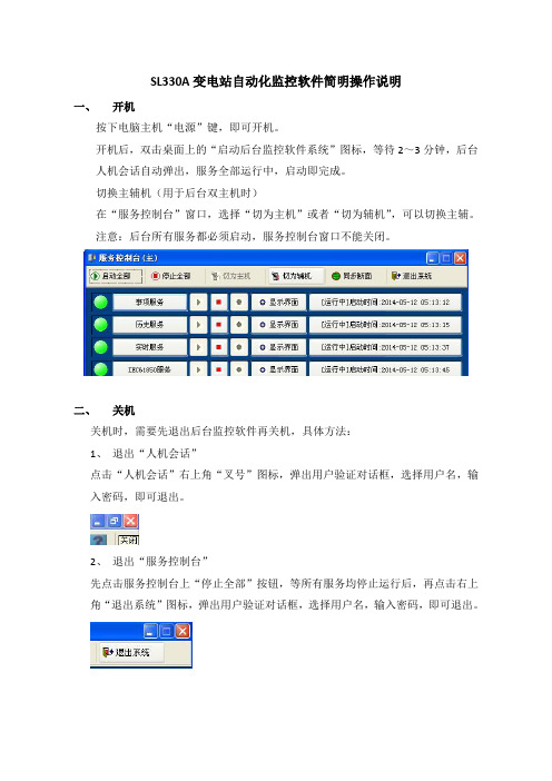
SL330A变电站自动化监控软件简明操作说明一、开机按下电脑主机“电源”键,即可开机。
开机后,双击桌面上的“启动后台监控软件系统”图标,等待2~3分钟,后台人机会话自动弹出,服务全部运行中,启动即完成。
切换主辅机(用于后台双主机时)在“服务控制台”窗口,选择“切为主机”或者“切为辅机”,可以切换主辅。
注意:后台所有服务都必须启动,服务控制台窗口不能关闭。
二、关机关机时,需要先退出后台监控软件再关机,具体方法:1、退出“人机会话”点击“人机会话”右上角“叉号”图标,弹出用户验证对话框,选择用户名,输入密码,即可退出。
2、退出“服务控制台”先点击服务控制台上“停止全部”按钮,等所有服务均停止运行后,再点击右上角“退出系统”图标,弹出用户验证对话框,选择用户名,输入密码,即可退出。
3、退出“SL330A系统控制台”点击右上角“叉号”图标,弹出用户验证对话框,选择用户名,输入密码,即可退出。
后台监控软件全部退出后,依次点“开始”——“关闭计算机”——“关闭”就可以关闭后台电脑了。
注意:请不要强行断电关机,以免损坏后台数据库系统。
三、监控软件使用3.1 画面浏览打开“人机会话”后,默认进入索引主页(1)点击“一次接线图”图标,可以进入主接线图进行查看。
(2)点击某个间隔出线的名称,可以进入相应的间隔查看该间隔的详细信息。
例如“35kV吉其线341间隔”,点击主接线图上的“”文字就可以进入35kV吉其线341间隔图;(3)点击间隔图上的“返回上一级”或者大标题,可以返回主接线图。
例如进入“35kV吉其线341间隔”后,点击大标题“35kV吉其线341间隔”或者“返回上一级”,都可以打开主接线图。
3.2报表浏览点击索引主页中的“报表”图标,进入报表索引要浏览某条线路的报表,点击相应的图标,进入该报表界面,再点击右上角的时间控件“”,弹出日历窗口,选择日期就可以查询某一天的对应报表值。
3.3 画面报警确认在画面上右击,选择“画面确认”单击,可以确认当前所打开画面中的报警。
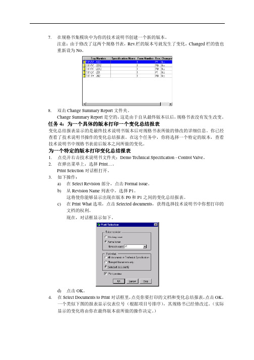
7. 在规格书集模块中为你的技术说明书创建一个新的版本。
注意:由于修改了这两个规格书表,Rev.栏的版本号就发生了变化,Changed 栏的值也重新设为No 。
8. 双击Change Summary Report 文件夹。
Change Summary Report 是空的,这是由于自从最终版本以后,规格书表没有发生改变。
任务4:为一个具体的版本打印一个变化总结报表变化总结报表显示的是最终技术说明书版本后对规格书表所做的修改的详细信息。
你已经查看了技术说明书操作的变化总结报表。
在这个任务中,你将选择一个特定的版本,查看技术说明书中规格书表前后版本之间所做的变化。
为一个特定的版本打印为一个特定的版本打印变化总结报表变化总结报表1. 点亮并右击技术说明书文件夹:Demo Technical Specification - Control Valve 。
2. 在弹出菜单上,选择Print…。
Print Selection 对话框打开。
3. 如下操作:a) 在Select Revision 部分,点击Formal issue 。
b) 从Revision Name 列表中,选择P1。
这将使你能够显示出现在版本P0和P1之间的变化总结报表。
c) 在Print What 选项,点击Selected documents ,获得选择技术说明书中你想打印的文档的权利。
现在,对话框显示如下。
d) 点击OK 。
4. 在Select Documents to Print 对话框里,点亮你要打印的文档和变化总结报表,点击OK 。
一个类似下图的报表显示仪表位号(根据项目号排序),其规格书已经修改过。
(实际显示的变化将由你在最终版本前所做的操作决定。
)5.点击打印报表。
接线模块这个模块允许你创建必要的面板和电缆,并连接控制回路,接线图如下。
选择下列任一选项,启动接线模块:在主工具栏上,点击。
在Module菜单上,选择Wiring。
1 SafetyThe IDL System and the VSC-L30 must be installed, commis-sioned and serviced only by adequately qualified personnel and in line with electrical engineering requirements. Read the Quickstart of VSC-L30 and Ruler E before starting the installation and make sure the Operating Instructions for the IDL system can be accessed during installation.Risk of injuries due to electrical current!The VSC-L30 is connected to the power supply (100 to 264 V AC/50 to 60 Hz).b Observe current safety regulations when working with electrical equipment.b Make sure the equipment has been deenergized before performing any installation work.2 Product SpecificationThe IDL system for item detection performs an analysis of letters and parcels on continuous belts, tilt trays and cross belt conveyor systems.IDL uses data from a Ruler E, which is mounted above the conveyor system. The Vision System Computer, VSC-L30 is used to analyze image data and communicate of results in the IDL System. Inside the VSC-L30 an iPC and a MSC800 control unit is mounted. In the VSC-L30 iPC, the Ruler E data is compared to a background reference where the difference is subjected to image processing that determines the presence of objects.When objects are detected the result values are calculated and reported to the MSC800 controller unit. Triggers,Encoders and other SICK devices in the same installation are also connected to the MSC800. When all results are ready the MSC800 sends the final result message to the client control system.3 System RequirementsPC for configuration and remote access of IDL:b PC Pentium III 500MHz minimumb RAM: 512 MB minimum (1 GB recommended)b Windows XP Professional SP3,Windows 7 Professional (32 / 64 bit)b Free disk space: 400 MB minimumb Monitor: 800 x 600 px, minimum 256 colors (65,536 colors (16 bit Hi color) recommended)b Ethernet card 100 Mbit/s or faster b USBFor access directly to the Ruler please see requirements for Ranger Studio in the Operating instructions.4 InstallationA thorough assembly and installation guide is included in the Operating Instructions.Important during installation:b Ensure that all laser safery requirements for the Ruler E camera is fulfilled. See the Ruler E user documentation for more information.b The laser of the Ruler may be activated as soon as the Ruler E is powered on. Avoid direct exposure to the laser beam. Avoid looking at the laser reflections.b Triggering parameters can be used to delay trigs for up to a cell length. The constraints of the triggering parameters should be considered when placing the photoelectric switch.b When delivered, the VSC-L30 is prepared for running in cell mode. If you intend to use the system in continuous mode, move the cables going to the encoder converter from OUT_2 and OUT_3 on the MSC800 to INC_1 and INC_2 respectively.b If the photoelectric switch or encoder is power supplied from the MSC800, make sure that the DIP switches SGND_4 - GND or SGND_5 - GND are set to ON.5 CommissioningThe IDL system must be commissioned by adequately quali-fied personnel only.The following software is used for the commissioning:b Ranger Studio Installed on the iPC b IDL application Installed on the iPC b SOPAS Download from , and installon the PC used for configuration.In-depth IDL Operating instructions are available for download from SICK. Access is given upon purchase of an IDL system.6 Service and Maintenanceb Spare parts for the devices that are present in the Item Detection system are handled as standard SICK products (Ruler E, iPC, MSC800, Ethernet switch, power supply).7 Further InformationSICK uses standard IP technology for its products, e.g. IO Link, industrial PCs. The focus here is on providing availability of products and services. SICK always assumes that the integrity and confidentiality of data and rights involved in the use of the above-mentioned products are ensured by customers themselves. In all cases, the appropriate security measures, e.g. network separation, firewalls, antivirus protection, patch management, etc., are always implemented by customers themselves, according to the situation.For more information on the Item Detection system, please refer to the Operating Instructions.For support issues, please contact your local sales office.More product and order information is also available on:Vision System Computer8014729 ∙ 2011-11All rights reserved Subject to change without prior noticeQ u i C k S ta r tAustraliaPhone +61 3 9497 4100 1800 334 802 – tollfree E-Mail **************.au Belgium/LuxembourgPhone +32 (0)2 466 55 66******************BrasilPhone +55 11 3215-4900******************.brCanadaPhone +1(952) 941-6780 1 800-325-7425 – tollfree **********************Ceská RepublikaPhone +420 2 57 91 18 50******************ChinaPhone +852-2763 6966******************.hk DanmarkPhone +45 45 82 64 00******************DeutschlandPhone +49 211 5301-301***************************EspañaPhone +34 93 480 31 00******************FrancePhone +33 1 64 62 35 00******************Great BritainPhone +44 (0)1727 831121******************.uk IndiaPhone +91–22–4033 8333*************************IsraelPhone +972-4-999-0590***************************ItaliaPhone +39 02 27 43 41******************JapanPhone +81 (0)3 3358 1341*********************MagyarországPhone +36 1 371 2680********************NederlandsPhone +31 (0)30 229 25 44******************NorgePhone +47 67 81 50 00************************ÖsterreichPhone +43 (0)22 36 62 28 8-0********************PolskaPhone +48 22 837 40 50******************RomâniaPhone +40 356 171 120 E-Mail **************RussiaPhone +7 495 775 05 30******************SchweizPhone +41 41 619 29 39*********************SingaporePhone +65 6744 3732***********************.sg South AfricaPhone +27 11 472 3733****************************.za South KoreaPhone +82-2 786 6321/4************************SlovenijaPhone +386 (0)1-47 69 990********************SuomiPhone +358-9-25 15 800******************SverigePhone +46 10 110 10 00******************TaiwanPhone +886 2 2375-6288********************.tw TürkiyePhone +90 216 528 50 00*******************.tr United Arab Emirates Phone +971 4 8865 878******************USA/MéxicoPhone +1(952) 941-6780 1 800-325-7425 – tollfree **********************More representatives and agencies atBCabinet Dimensional Drawings [mm (inch)]Cable Entries1 234 51 4 x M fitting, metal, M16 x 1.5 (0.06 inch)55 x M fitting, metal, M16 x 1.5 (0.06 inch)(0.12 ... 0.28 inch)Ruler E Encoder cable, M12 8-pin - open 5 m a6029331Ruler E Gigabit Ethernet cable, Cat. 6, 5 m c 6032321Other cable lengths are availableDiPC – Ruler network 192.168.0.1interfacehalf/full duplexEFTechnical DataCablesDevice IP Addresses2(BR)7(BL)1(W)ONOFFS G N D _5 - G N D S G N D _4 - G N D1(W)4(Y)2(BRN)3(GRN)145827X4.1X4.2I N C _1I N C _2INC X4X4.7X4.8+24 V S G N D _4X5.1T R G _1TRIGGER X5X5.7X5.8+24VS G N D _5X7.2O U T _2OUT X7Trig 124V 0V A B24VGNDCONVErtErruLEr E – CONNECtOrSMSC800 – BLOCkSPower connector Encoder connectorPhotoelectric switchEncoder2(BR)7(BL)1(W)ONOFFS G N D _5 - G N D S G N D _4 - G N D1(W)4(Y)2(BRN)3(GRN)145827X5.1T R G _1TRIGGER X5X5.7X5.8+24VS G N D _5X7.2X7.3O U T _2O U T _3OUT X7X7.4O U T _4Trig 124V0VCONVErtErruLEr E – CONNECtOrSMSC800 – BLOCkSPower connector Encoder connectorPhotoelectric switch(Colors are valid for cable types STL-1208 and DOL-1208 respectively)。
2.0 SYSLOG 操作手册8DA22501T029ASCVQ ED1.4 RL Oct 24th 2012- 1 -文档号: 版本号: 版本状态 :发布 日期:2012年11月22日2.0 SYSLOG 操作手册For SP6B125目录一. 前言 (2)1.1 文档简介 (2)1.2 读者对象 (2)1.3 文档约定 (2)1.3.1 命令语法约定 (2)1.3.2 文档标志约定 (3)1.4 相关文档 (3)二. 配置SYSLOG (4)2.1 SYSLOG简介 (4)2.1.1 SYSLOG介绍 (4)2.1.2 SYSLOG作用 (5)2.1.3 Syslog级别 (5)2.2 SYSLOG 功能配置 (6)2.3 SYSLOG配置案例 (7)2.4 配置3CDaemon (8)附录A 缩略语 (12)一. 前言本命令行配置手册仅作为使用指导,实际产品可能会由于版本升级或其他原因,与手册描述有轻微差异。
1.1 文档简介概要描述本产品包括几个分册,以及本分册的主要内容。
1.2 读者对象本手册主要适用于期望了解本产品主要技术特性和使用方法的用户以及如下工程师:⏹网络规划人员⏹现场技术支持与维护人员⏹负责网络配置和维护的网络管理员1.3 文档约定1.3.1 命令语法约定命令行模式分为视图模式、系统模式、配置模式和节点配置模式,hansi配置模式五种。
1.3.2 文档标志约定1.4 相关文档列出与该命令行操作手册相配套的其它文档,如命令行手册、安装手册等,手册名称用书名号《》括起来。
二. 配置SYSLOGSyslog是一种工业标准的协议,可用来记录设备的日志。
在UNIX系统,路由器、交换机等网络设备中,系统日志(System Log)记录系统中任何时间发生的大小事件。
管理者可以通过查看系统记录,随时掌握系统状况。
UNIX的系统日志是通过syslogd 这个进程记录系统有关事件记录,也可以记录应用程序运作事件。
用户操作手册请您在使用前仔细阅读本操作手册,以获得更好的使用体验。
目录主要特点 (3)LS30包装盒内部件 (4)注意事项 (5)免责声明 (5)商标声明 (5)本说明书中特定符号作用 (6)1准备 71 各部分介绍 (8)2 界面 (10)3 使用电池 (11)安装电池 (11)取出电池 (12)4 锁定按键(HOLD) (13)5 开关机.............................................146 设置时间日期 (15)2录音 161 录音基本操作 (17)2 录音模式 (19)课堂模式 (19)口袋模式 (19)手动录音模式 (20)设置录音模式 (21)3 手动调节输入增益(LEVEL) (22)4 AGC(自动调节增益) (23)5 声控录音(VOR) (25)6 低切降噪(LOW CUT) (27)7 外置输入设备 (28)3播放 291 播放基本操作 (30)2 变速播放(SPEED) (32)3 A-B重复播放 (34)4 循环模式 (35)5 使用扬声器或耳机 (36)6 删除文件 (37)4菜单功能 381 菜单操作方法 (39)2 选项介绍 (40)5传输数据 471 系统及硬件要求..............................482 文件夹结构 (49)3 传输文件 (50)6故障排除 531 系统提示 (54)2 常见问题 (58)7其他信息 611 规格 (62)2 安全说明 (64)主要特点一键录音:长按REC键直接 进入课堂模式移植多项专业采访机技术环境音抑制系统变速复听不变调广播级专业降噪语音质量提升140小时录音 / 声控录音/ 无损PCM / A-B复读衣服口袋和包内清晰录音LS30包装盒内部件• LS30包装盒内包括如下标准部件各一件,购买产品时,请对照此装箱清单认真核实主机、 标准附件、选配附件是否齐全。
OWNER’S GUIDE1.Read these instructions.2.Keep these instructions.3.Heed all warnings.4.Follow all instructions.5.Do not use this apparatus near water.6.Clean only with a dry cloth.7.Do not block any ventilation openings. Install in accordance with the manufacturer’s instructions.8.Do not install near any heat sources such as radiators, heatr egisters, stoves or other apparatus (including amplifiers) thatp roduce heat.9.Do not defeat the safety purpose of the polarized or g rounding-type plug. A polarized plug has two blades with one wider than the other. A grounding-type plug has two blades and a third grounding prong. The wide blade or the third prong is provided for your safety. If the provided plug does not fit into your outlet, consult ane lectrician for replacement of the obsolete outlet.10.Protect the power cord from being walked on or pinched, particularly at plugs, convenience receptacles and the point where they exit from the apparatus.11.Only use attachments/accessories specified by the manufacturer.e only with the cart, stand, tripod, bracket or tablespecified by the manufacturer or sold with thea pparatus. When a cart is used, use caution whenm oving the cart/apparatus combination to avoid injuryfrom tip-over.13.Unplug this apparatus during lightning storms or when unused for long periods of time.14.Refer all servicing to qualified service personnel. Servicing is required when the apparatus has been damaged in any way, such as power supply cord or plug is damaged, liquid has been spilled or objects have fallen into the apparatus, or the apparatus has been exposed to rain or moisture, does not operate normally or has been dropped.15.Do not expose this apparatus to dripping or splashing and ensure that no objects filled with liquids, such as vases, are placed on the apparatus.16.To completely disconnect this apparatus from the AC Mains,d isconnect the power supply cord plug from the AC receptacle.17.The mains plug of the power supply cord shall remain readily operable.18.Do not expose batteries to excessive heat such as sunshine, fire or the like.The lightning flash with arrowhead symbol, withinan equilateral triangle, is intended to alert theuser to the presence of uninsulated “dangerousv oltage” within the product’s enclosure that maybe of sufficient magnitude to constitute a risk of e lectric shock to persons.The exclamation point within an equilateral triangle isintended to alert the user to the presence of importantoperating and maintenance (servicing) instructions inthe literature accompanying the product. WARNING: To reduce the risk of fire or electric shock, do not expose this apparatus to rain or moisture.IMPORTANT SAFETY INSTRUCTIONS2For more than 60 years, JBL has been providing audio equipment toconcert halls, recording studios and movie theaters around theworld, and has become the hands-down choice of leading recordingartists and sound engineers.With the JBL LS Series, innovative technologies such as pure-titani-um compression tweeters, Elliptical Oblate Spheroidal™(EOS) wave-guides and PolyPlas™transducer reinforcement are available to you.Enjoy!UNPACKING THE SUBWOOFERIf you suspect damage from transit, report it immediately to yourdealer. Keep the shipping carton and packing materials for futureuse.PLACEMENTSince the installation of a subwoofer can be somewhat morec omplicated than installation of full-range speakers, it is essentialthat you read this section very carefully prior to connecting thes ubwoofer to your system. Should you have questions relating toyour installation, it is advisable to call your dealer or distributor foradvice.The performance of the subwoofer is directly related to itsp lacement in the listening room and how you align the subwooferwith its satellite speakers. Setting the volume of the subwoofer inrelationship to the left and right speakers is also of criticali mportance because it is essential that the subwoofer integratesmoothly with the entire system. Setting the subwoofer’s volumelevel too high will result in overpowering, boomy bass. Setting thevolume level too low will negate the benefits of the subwoofer.Here are several additional facts on installation that may proveu seful. It is generally believed by most audio authorities that lowf requencies (below 125Hz) are nondirectional and, therefore,p lacement of a subwoofer within any listening room is not critical.While in theory it is true that the larger wavelengths of extremelylow frequencies are basically nondirectional, the fact is that, wheninstalling a subwoofer within the limited confines of a room,r eflections, standing waves and absorptions generated within theroom will strongly influence the performance of any subwoofers ystem. As a result, specific location of the subwoofer becomesimportant, and we strongly recommend that you experiment withplacement before choosing a final location.Placement will depend upon your room and the amount and qualityof bass required (for example, whether or not your room permitsplacement of the subwoofer near either satellite).Figure 1.This example shows the subwoofer positioned behind theright-channel satellite speaker to re-create the actual location ofbass instruments in an orchestra and/or add impact to movie sound-tracks.INSTALLING SPIKED FEETFour metal spikes are supplied for use when the speaker is to beplaced on a carpeted surface; using them decouples the speakerfrom the floor to prevent unwanted damping. To insert the spikes,gently lay the speaker on its side (not its front or back) on a soft,nonabrasive surface, and unscrew the rubber-tipped feet (store in asafe place). Each spike then screws into the threaded insert in eachcorner. Make sure all four spikes are screwed in completely for sta-bility. To protect the surface of uncarpeted floors, set each spike intoan included metal coaster.NEVER drag the speaker to move it, as this will damage the spikes,the feet, the wood cabinet itself, and/or the floor. Always lift thespeaker and carry it to its new location.JBL® LS120P POWERED SUBWOOFER34REAR PANELCONTROLS AND CONNECTIONSSYSTEM CONNECTIONSIf you have a Dolby ®5“Normal.”POWER ONPlug your subwoofer’s AC cord into a wall outlet. Do not use theo utlets on the back of the receiver.Initially set the Subwoofer-Level Control 2to the “min” position. Turn on your sub by pressing the Power Switch 6on the rear panel. Turn on your entire audio system and start a CD or movie soundtrack at a moderate level.AUTO ON/STANDBYWith the Power Switch 6in the ON position, the Status LED 4on back will remain lit in red or green to indicate the On/Standby mode of the subwoofer.RED = STANDBY (no signal detected, Amp Off)GREEN = ON (signal detected, Amp On)The subwoofer will automatically enter the Standby mode after approximately 10 minutes when no signal is detected from yours ystem. The subwoofer will then power ON instantly when a signal is detected. During periods of normal use, the Power Switch 6can be left on. You may turn off the Power Switch 6for extended periods of nonoperation, e.g., when you are away on vacation.GETTING STARTEDTurn your Subwoofer-Level Control 2up to the halfway position. If no sound emanates from the subwoofer, check the AC-line cord and input cables. Are the connectors on the cables making properc ontact? Is the AC plug connected to a “live” receptacle? Has the Power Switch 6been pressed to the “On” position? Once you have confirmed that the subwoofer is active, proceed by playing a CD, record or cassette. Use a selection that has ample bass information. ADJUST LEVELSet the overall volume control of the preamplifier or stereo to ac omfortable level. Adjust the Subwoofer-Level Control 2until you obtain a pleasing blend of bass. Bass response should not over -power the room but rather be adjusted so there is a harmonious blend across the entire musical range. Many users have a tendency to set the subwoofer volume too loud, adhering to the belief that a subwoofer is there to produce lots of bass. This is not entirely true.A subwoofer is there to enhance bass, extending the response of the entire system so the bass can be felt as well as heard. However, overall balance must be maintained or the music will not soundn atural. An experienced listener will set the volume of the subwoofer so its impact on bass response is always there but never obtrusive. PHASE CONTROLThe Phase Switch 0determines whether the subwoofer speaker’s pistonlike action moves in and out with the main speakers, 0˚, or opposite the main speakers, 180˚. Proper phase adjustment depends on several variables such as room size, subwoofer placement and listener position. Adjust the phase switch to maximize bass output at the listening position.CROSSOVER ADJUSTMENTThe Crossover Adjustment Control 3determines the highestf requency at which the subwoofer reproduces sounds. If your main speakers can comfortably reproduce some low-frequency sounds, set this control to a lower frequency setting, between 50Hz and100Hz. This will concentrate the subwoofer’s efforts on the ultradeep bass sounds required by today’s films and music.If you are using smaller bookshelf speakers that do not extend to the lower bass frequencies, set the Crossover Adjustment control to a higher setting, between 120Hz and 150Hz.NOTE:This control will have no effect if the LFE/Normal Selector 1 is set to LFE. If you have a Dolby Digital or DTS processor/receiver, the Low-Pass Frequency is set by the processor/receiver. Consult your owner’s manual to learn how to view or change this setting.The enclosure may be cleaned using a soft cloth to remove finger-prints or to wipe off dust.The grille may be gently vacuumed. Stains may be removed with an aerosol cleaner, following its instructions. Do not use any solvents on the grille.All wiring connections should be inspected and cleaned or remade periodically. The frequency of maintenance depends on the metals involved in the connections, atmospheric conditions and otherf actors, but once per year is the minimum.In the event that your subwoofer ever needs service, contact your local JBL dealer or distributor, or visit for a service center near you.OPERATION 6MAINTENANCE AND SERVICE7SPECIFICATIONSLS 120PFrequency Response 25Hz – 150Hz Amplifier RMS Power 400 Watts Amplifier Peak Dynamic Power †700WattsCrossover Frequency 50Hz – 150Hz;24dB/octave, continuously adjustable Driver300mm (12") PolyPlas ™Dimensions (H x W x D)487mm x 375mm x 425mm (enclosed only)(19-3/16" x 14-3/4" x 16-3/4")Dimensions (H x W x D)500mm x 375mm x 438mm (with feet, controls, grille, etc.)(19-11/16" x 14-3/4" x 17-1/4")Weigh t25.8kg (57 lb)†The Peak Dynamic Power is measured by recording the highest center-to-peak voltagem easured across the output of a resistive load equal to minimum impedance of the transducer,using a 50Hz sine wave burst, 3 cycles on, 17 cycles off.Laurent RaultHarman Consumer Group, Inc.Château du Loir, France 5/07Laurent RaultHarman Consumer Group, Inc.Château du Loir, France 5/07Features, specifications and appearance are subject to change without notice.JBL is a trademark of Harman International Industries, Incorporated, registeredin the United States and/or other countries. Elliptical Oblate Spheroidal, PolyPlas and Pro Sound Comes Home are trademarks of Harman International Industries, Incorporated. Dolby is a registered trademark of Dolby Laboratories.DTS is a registered trademark of DTS, Inc.。

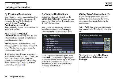
Entering a DestinationBy Previous DestinationEvery time you enter a destination, that destination is saved by the system. It can store the last 50 destinations entered. Select Previous Destination from the Enter destination by screen to choose one of those destinations.After you select Previous Destination, the display lists the last 50 destinations entered, with the most recent appearing first.NOTE: Because both the Home and Personal Address list can be protected by a PIN, they do not show up in the previous destination list.Scroll through the list and select the desired destination you want. Once you select the desired destination, the system then displays the Calculating route to screen (see Driving to Your Destination on page 33).By Today’s DestinationsUsing the other selections from theEnter destination by screen, you canstore a list of up to five destinations asToday’s Destinations.The system automatically sorts thedestinations stored in the Today’sDestinationslist for the best path.If the displayed list shows your plans,select OK. The system will guide youto the destination according to the orderof the list. When you reach thedestination, it will be automaticallyremoved from the list.Editing Today’s Destinations ListIf you change your plans, you canmodify the list: changing the order,skipping, deleting, or changing thedestination.Select Edit, then select the destinationyou want to edit. The display changesto:You have five choices; Up, Down,Skip/Include, Delete/Add,andChange.Navigation System30。
用户操作手册请您在使用前仔细阅读本操作手册,以获得更好的使用体验。
目录主要特点 (3)LS30包装盒内部件 (4)注意事项 (5)免责声明 (5)商标声明 (5)本说明书中特定符号作用 (6)1准备 71 各部分介绍 (8)2 界面 (10)3 使用电池 (11)安装电池 (11)取出电池 (12)4 锁定按键(HOLD) (13)5 开关机.............................................146 设置时间日期 (15)2录音 161 录音基本操作 (17)2 录音模式 (19)课堂模式 (19)口袋模式 (19)手动录音模式 (20)设置录音模式 (21)3 手动调节输入增益(LEVEL) (22)4 AGC(自动调节增益) (23)5 声控录音(VOR) (25)6 低切降噪(LOW CUT) (27)7 外置输入设备 (28)3播放 291 播放基本操作 (30)2 变速播放(SPEED) (32)3 A-B重复播放 (34)4 循环模式 (35)5 使用扬声器或耳机 (36)6 删除文件 (37)4菜单功能 381 菜单操作方法 (39)2 选项介绍 (40)5传输数据 471 系统及硬件要求..............................482 文件夹结构 (49)3 传输文件 (50)6故障排除 531 系统提示 (54)2 常见问题 (58)7其他信息 611 规格 (62)2 安全说明 (64)主要特点一键录音:长按REC键直接 进入课堂模式移植多项专业采访机技术环境音抑制系统变速复听不变调广播级专业降噪语音质量提升140小时录音 / 声控录音/ 无损PCM / A-B复读衣服口袋和包内清晰录音LS30包装盒内部件• LS30包装盒内包括如下标准部件各一件,购买产品时,请对照此装箱清单认真核实主机、 标准附件、选配附件是否齐全。
• 包装盒内的部件可能会因地域不同而有所差异,详情请咨询当地经销商。
USB连接线LS30数字录音机保修说明产品合格证手提挂绳用户操作手册(保存在机器内存中,请用户自行妥善保存。
若有遗失请至官网下载。
)防风海绵注意事项免责声明商标声明• 版权所有。
事前未经英夫美迪公司书面批准,本说明书或其中介绍的软件无论全部或部分 均不得复制、翻译或缩减成计算机可读的数据。
• 英夫美迪公司对无论由本说明书、软件、包含的信息及其使用引发的还是其相关的侵权、 契约等造成的意外、后果或特殊损失不承担任何责任。
• 英夫美迪公司保留在任何时候对此说明书或其所包含信息进行修改而不做通知的权利。
• 这里介绍的软件可能受单独的用户许可协议条款制约。
• IBM 和 PC/AT 是国际商业录音机公司的注册商标。
• Microsoft 和 Windows 是 Microsoft Corporation 在美国和其他国家的注册商标。
• Apple 和 Macintosh 是 Apple Computer Inc.在美国和其他国家的注册商标。
• Pentium 是 Intel Corporation 的注册商标。
• 所有其他商标和注册商标是相应拥有者的商标或注册商标。
本说明书中特定符号作用准备11 各部分介绍14671内置麦克风2液晶显示屏注:128*64像素LCD液晶显示屏3REC录音键/长按直接进入课堂模式4停止/CANCEL取消键注:停止录音或播放;菜单中用于后退或取消操作。
5播放/暂停/OK确定键注:播放文件;暂停录音或播放;菜单中用于进入或确认操作。
6LEVEL+/SPEED+/向上键7快进/下一曲/向右键注:菜单中,用于进入或确认操作。
8快退/上一曲/向左键注:菜单中,用于后退或取消操作。
9LEVEL-/SPEED-/向下键10DELETE删除键(需长按进入DELETE菜单)11FOLDER文件夹/MENU菜单键注:短按此键更换文件夹;长按此键进入设置菜单。
12扬声器13USB接口8101314MIC IN外置麦克/LINE IN线路输入插孔15耳机/LINE OUT线路输出16耳机音量+17耳机音量-18A-B键19HOLD锁定开关20POWER电源键21手提挂绳孔22电池仓注:使用2节AAA型号干电池或充电电池。
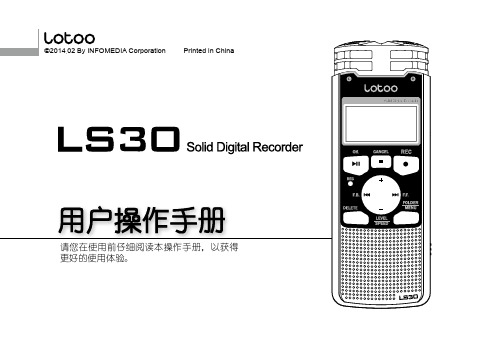
19202116171814151准备课堂模式 口袋模式 无损PCM 高质量 标准质量AGC/声控录音 AGC 声控录音低切降噪输入设备 内置麦克 外置麦克 线路输入当前选定文件夹 ~ A~H文件夹共8个文件夹可选循环模式顺序播放无标志 单曲循环全部循环A-B循环模式电池电量信息(录音)当前时间(播放)文件创建时间已录音/播放时长文件名称(录音)剩余可录音时间(播放)文件剩余播放时间状态标志 课堂模式标志 口袋模式标志 录音 暂停录音停止状态正常播放 暂停播放 ~ 变速播放 / 快退/快进录音/播放电平1准备安装电池如图所示,滑动并打开电池仓盖。
按照电池仓盖内极性所示插入两节AAA型号电池。
关闭电池仓盖。
3 使用电池LS30通过两节AAA型号干电池或充电电池供电。
【系统设置>电池类型】选项可设置电池类型,请根据电池选择正确的电池类型,以便更精确的指示电池电量。
打开电池仓安装电池关闭电池仓• 首次使用或长时间放置后重新使用录音机,可能需要设定时间信息。
• 更换电池时,时间信息将保持一段时间。
若长时间不插入电池,这些信息可能丢失。
电池组电量显示• 当电池电量耗尽,出现“电量不足”的提示时,请您及时更换电池组,以保证录音机正常使用。
取出电池滑动并打开电池仓盖。
取出两节电池。
关闭电池仓盖。
• 不使用录音机时,请取出电池组,以免电池漏液腐坏LS30。
• 请使用两个相同型号电池,并且请勿新旧电池混用,否则可能造成损坏。
• HOLD向上拨动:按键被锁定。
• HOLD向下拨动:按键解锁。
向上拨动HOLD开关可以锁定所有按键,防止在录音或播放过程中由于误碰而引发错误。
当键盘锁定后,无论您触碰任何按键均无法生效,屏幕出现提示:“已锁定”。
若您需要进行操作,请将HOLD开关向下拨动,并重新尝试。
开机状态下长按POWER键,可以关闭录音机。
关机状态下长按POWER键,可以打开录音机。
• 本操作手册中其他操作均假设在开机状态下进行。
若HOLD开关为锁定状态,无法执行开关机或其他操作,屏幕会提示“已锁定”。
请将HOLD开关解锁并重新操作。
1准备请在首次开机或长时间没有插入电池重新使用时,设置系统时间日期。
设置正确的系统时间日期,可以保证在录音中记录的时间信息的准确性。
• 录音状态下,屏幕显示当前日期时间。
• 播放状态下,屏幕显示文件创建的日期时间。
信息可能丢失。
停止状态下长按<FOLDER/MENU>键,进入设置菜单。
按< / >键选择【系统设置】,按< >或< >键进入。
按< / >键选【日期时间】,按< >键确认。
按< >< >键选择需要更改的时间日期信息,按< / >键设置数值,设置完毕按< >键。
按< >或<■>键返回上级菜单,或直接按<FOLDER/MENU>键退出设置菜单。
录音21 录音基本操作开始录音• 将麦克风指向声源方向。
• 按<●>键开始录音。
• 屏幕状态图标显示为 ●,同时录音提示灯闪烁,表 示录音正在进行。
暂停录音• 录音过程中按< >键暂停录音。
• 再次按< >键,将继续录音。
停止录音• 长按<■>键直至停止录音。
选择录音文件夹• 按<FOLDER/MENU>键,弹出文件夹列表。
• 按< / >键选择目标文件夹,按< >键确认。
• 按<■>或< >键退出。
停止状态下长按<●>键,可直接进入【课堂模式】录音。
• 录音过程中,请尽量不要在话筒周围频繁活动,否则可能录入不必要的噪音。
• 录音前请检查电池电量,确认有充足电量以保证录音正常进行。
• LS30内置A、B、C、D、E、F、G、H共8个文件夹。
您可以选择其中一个作为录音文件的存储文件夹,录音机默 认文件夹为【A文件夹】。
• LS30不支持新建文件夹,同时无法识别从计算机复制的文件夹。
若您需要从计算机外部拷贝音乐文件并通过录 音机听取,请放置于以上8个文件夹的根目录内。
• 录音机可以显示文件夹中的前1000个录音文件。
• 录音文件默认命名规则为从USER0001开始依次递增,若有已存在的文件名将自动跳过。
当USER0001~USER9999完全使用后,当前文件夹将无法保存新录音。
• 文件按文件名的字母顺序排列,开机或录音结束后自动显示文件夹内默认命名规则下序号最大的录音文件。
• 录音过程中,通过耳机听取声音,即为真实的录音效果。
您可以根据效果调节增益等设置。
2 录音模式一种适合课堂录音的自动录音模式,可以根据当前课堂环境,自动调节录音设置。
捕捉老师话语中的每一个细节,最好的还原课堂效果。
• 长按<●>键,可直接开始【课堂模式】录音。
【课堂模式】录音。
• 【课堂模式】录音文件为MP3格式。
• 【课堂模式】录音为自动录音模式,自动根据环境进行参数调节。
课堂模式 (长按REC键直接进入)口袋模式每当将录音笔放置在口袋或衣袋中进行隐蔽录音,声音总是干瘪枯燥,甚至模糊不清。
而LS30专门针对口袋模式进行了自动优化,有别于普通录音模式,能够有效提升隐蔽录音时的效果。
• 【口袋模式】录音文件为MP3格式。
• 【口袋模式】录音为自动录音模式,自动根据环境进行参数调节。
以下三种录音模式,为手动调节模式。
在这种模式下,可手动调节录音参数:LEVEL、AGC、声控录音、低切降噪、外置输入设备等。
【无损PCM】LS30支持CD音质的PCM无损文件录音,这种高品质录音格式使用无损失编码方式,适合更加丰富多样的重要场合,保留更多丰富细节和真实度。
无损PCM格式:WAV-16bit-44.1KHz【高质量】高质量格式:MP3-48KHz-256kbps【标准质量】标准质量格式:MP3-48KHz-128kbps 手动录音模式• 课堂模式、口袋模式是自动录音模式。
在这两种模式下,【LEVEL】【AGC】【声控录音】【低切降噪】【外置输入设备】这些参数设置不能生效。
屏幕显示标志为录音模式标志>键返回上级菜单,或直接按<FOLDER/MENU>按<●>键开始录音。
长按<■>键停止录音。
• AGC功能开启时,无法手动调节输入增益。