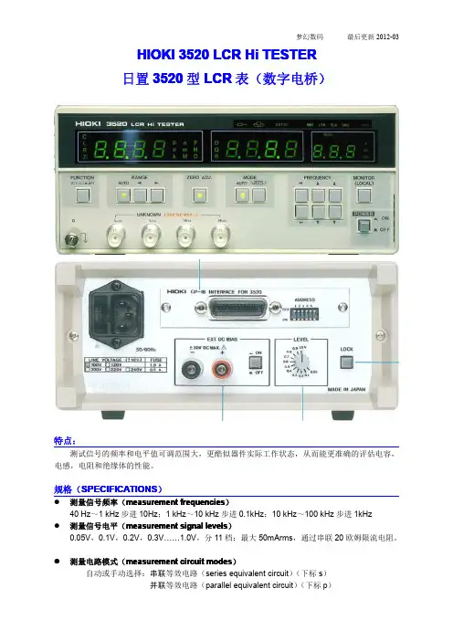
GL3520方案测试报告
- 格式:doc
- 大小:132.50 KB
- 文档页数:3
METHOD 3520CCONTINUOUS LIQUID-LIQUID EXTRACTION1.0SCOPE AND APPLICATION1.1This method describes a procedure for isolating organic compounds from aqueous samples. The method also describes concentration techniques suitable for preparing the extract for the appropriate determinative steps described in Sec. 4.3 of Chapter Four.1.2This method is applicable to the isolation and concentration of water-insoluble and slightly soluble organics in preparation for a variety of chromatographic procedures.1.3Method 3520 is designed for extraction solvents with greater density than the sample. Continuous extraction devices are available for extraction solvents that are less dense than the sample. The analyst must demonstrate the effectiveness of any such automatic extraction device before employing it in sample extraction.1.4This method is restricted to use by or under the supervision of trained analysts. Each analyst must demonstrate the ability to generate acceptable results with this method.2.0SUMMARY OF METHOD2.1 A measured volume of sample, usually 1 liter, is placed into a continuous liquid-liquid extractor, adjusted, if necessary, to a specific pH (see Table 1), and extracted with organic solvent for 18 - 24 hours.2.2The extract is dried, concentrated (if necessary), and, as necessary, exchanged into a solvent compatible with the cleanup or determinative method being employed (see Table 1 for appropriate exchange solvents).3.0INTERFERENCES3.1Refer to Method 3500.3.2The decomposition of some analytes has been demonstrated under basic extraction conditions required to separate analytes. Organochlorine pesticides may dechlorinate, phthalate esters may exchange, and phenols may react to form tannates. These reactions increase with increasing pH, and are decreased by the shorter reaction times available in Method 3510. Method 3510 is preferred over Method 3520 for the analysis of these classes of compounds. However, the recovery of phenols may be optimized by using Method 3520 and performing the initial extraction at the acid pH.4.0APPARATUS AND MATERIALS4.1Continuous liquid-liquid extractor - Equipped with polytetrafluoroethylene (PTFE) or glass connecting joints and stopcocks requiring no lubrication (Kontes 584200-0000, 584500-0000, 583250-0000, or equivalent).CD-ROM3520C - 1Revision 3December 19964.2Drying column - 20 mm ID Pyrex® chromatographic column with Pyrex® glass wool at bottom and a PTFE stopcock.NOTE:Fritted glass discs are difficult to decontaminate after highly contaminated extracts have been passed through. Columns without frits may be purchased.Use a small pad of Pyrex® glass wool to retain the adsorbent. Prewash theglass wool pad with 50 mL of acetone followed by 50 mL of elution solvent priorto packing the column with adsorbent.4.3Kuderna-Danish (K-D) apparatus4.3.1Concentrator tube - 10-mL graduated (Kontes K-570050-1025 or equivalent).A ground glass stopper is used to prevent evaporation of extracts.4.3.2Evaporation flask - 500-mL (Kontes K-570001-500 or equivalent). Attach toconcentrator tube with springs, clamps, or equivalent.4.3.3Snyder column - Three-ball macro (Kontes K-503000-0121 or equivalent).4.3.4Snyder column - Two-ball micro (Kontes K-569001-0219 or equivalent).4.3.5Springs - 1/2 inch (Kontes K-662750 or equivalent).NOTE:The following glassware is recommended for the purpose of solvent recovery during the concentration procedures requiring the use of Kuderna-Danishevaporative concentrators. Incorporation of this apparatus may be requiredby State or local municipality regulations that govern air emissions of volatileorganics. EPA recommends the incorporation of this type of reclamationsystem as a method to implement an emissions reduction program. Solventrecovery is a means to conform with waste minimization and pollutionprevention initiatives.4.4Solvent vapor recovery system (Kontes K-545000-1006 or K-547300-0000, Ace Glass 6614-30, or equivalent).4.5Boiling chips - Solvent-extracted, approximately 10/40 mesh (silicon carbide or equivalent).4.6Water bath - Heated, with concentric ring cover, capable of temperature control (± 5E C). The bath should be used in a hood.4.7Vials - 2-mL, glass with PTFE-lined screw-caps or crimp tops.4.8pH indicator paper - pH range including the desired extraction pH.4.9Heating mantle - Rheostat controlled.4.10Syringe - 5-mL.CD-ROM3520C - 2Revision 3December 1996CD-ROM 3520C - 3Revision 3December 19965.0REAGENTS5.1Reagent grade chemicals shall be used in all tests. Unless otherwise indicated, it isintended that all reagents shall conform to the specifications of the Committee on AnalyticalReagents of the American Chemical Society, where such specifications are available. Other gradesmay be used, provided it is first ascertained that the reagent is of sufficiently high purity to permit itsuse without lessening the accuracy of the determination. Reagents should be stored in glass toprevent the leaching of contaminants from plastic containers.5.2Organic-free reagent water - All references to water in this method refer to organic-freereagent water, as defined in Chapter One.5.3Sodium hydroxide solution (10N), NaOH. Dissolve 40 g NaOH in organic-free reagentwater and dilute to 100 mL. Other concentrations of hydroxide solutions may be used to adjustsample pH, provided that the volume added does not appreciably change (e.g., <1%) the totalsample volume.5.4Sodium sulfate (granular, anhydrous), Na SO . Purify by heating at 400E C for 4 hours24in a shallow tray, or by precleaning the sodium sulfate with methylene chloride. If the sodium sulfateis precleaned with methylene chloride, a method blank must be analyzed, demonstrating that thereis no interference from the sodium sulfate.5.5Sulfuric acid solution (1:1 v/v), H SO . Slowly add 50 mL of H SO (sp. gr. 1.84) to 5024 24mL of organic-free reagent water. Other concentrations of acid solutions may be used to adjustsample pH, provided that the volume added does not appreciably change (e.g., <1%) the totalsample volume.5.6Extraction/exchange solvents - All solvents must be pesticide quality or equivalent.5.6.1Methylene chloride, CH Cl , boiling point 39E C. 225.6.2Hexane, C H , boiling point 68.7E C.6145.6.32-Propanol, CH CH(OH)CH , boiling point 82.3E C. 335.6.4Cyclohexane, C H , boiling point 80.7E C. 6125.6.5Acetonitrile, CH CN, boiling point 81.6E C.36.0SAMPLE COLLECTION, PRESERVATION, AND HANDLINGSee the introductory material to this chapter, Organic Analytes, Sec. 4.1.7.0PROCEDURE7.1Using a 1-liter graduated cylinder, measure 1 liter (nominal) of sample. Alternatively, ifthe entire contents of sample bottle are to be extracted, mark the level of sample on the outside ofthe bottle. If high concentrations are anticipated, a smaller sample volume may be taken and dilutedto 1-L with organic-free reagent water. It is recommended that if high analyte concentrations areanticipated, samples should be collected in smaller sample bottles and the whole sample used.7.2Pipet 1.0 mL of the surrogate spiking solution into each sample in the graduated cylinder (or sample bottle) and mix well. (See Method 3500 and the determinative method to be used for details on the surrogate standard solution and matrix spiking solution).7.2.1For the sample in each batch (see Chapter One) selected for use as a matrixspike sample, add 1.0 mL of the matrix spiking standard.7.2.2If Method 3640, Gel-Permeation Cleanup, is to be employed, add twice thevolume of the surrogate spiking solution and the matrix spiking standard, since half of the extract is not recovered from the GPC apparatus. (Alternatively, use 1.0 mL of the spiking solutions and concentrate the final extract to half the normal volume, e.g., 0.5 mL instead of1.0 mL).7.3Check the pH of the sample with wide-range pH paper and adjust the pH, if necessary, to the pH indicated in Table 1, using 1:1 (v/v) sulfuric acid or 10 N sodium hydroxide. Lower concentrations of acid or base solution may be employed, provided that they do not result in a significant change (<1%) in the volume of sample extracted (see Secs. 5.3 and 5.5).7.4Add 300 - 500 mL of methylene chloride to the distilling flask of the extractor. Add several boiling chips to the flask.7.5Quantitatively transfer the sample from the graduated cylinder (or sample bottle) to the extractor. Use a small volume of methylene chloride to rinse the cylinder (or bottle) and transfer this rinse solvent to the extractor. Add organic-free reagent water to the extractor, if needed, to ensure proper operation and extract for 18-24 hours. If the sample was transferred directly from the sample bottle, refill the bottle to the mark made in Sec. 7.1 with water and then measure the volume of sample that was in the bottle.7.6Allow the extractor to cool, then detach the boiling flask. If extraction at a secondary pH is not required (see Table 1), the extract is dried and concentrated using one of the techniques described in Secs. 7.10 - 7.11.7.7If a pH adjustment and second extraction is required (see Table 1), carefully, while stirring, adjust the pH of the aqueous phase to the second pH indicated in Table 1. If the extracts are to be analyzed separately (see Sec. 7.8), attach a clean distilling flask containing 500 mL of methylene chloride to the continuous extractor. Extract for 18-24 hours, allow to cool, and detach the distilling flask. If the extracts are not to be analyzed separately, then the distilling flask and solvent need not be changed and may be used for the second pH extraction.7.8If performing GC/MS analysis (Method 8270), the acid/neutral and base extracts may be combined prior to concentration. However, in some situations, separate concentration and analysis of the acid/neutral and base extracts may be preferable (e.g., if for regulatory purposes the presence or absence of specific acid/neutral and base compounds at low concentrations must be determined, separate extract analyses may be warranted).7.9Perform concentration (if necessary) using the Kuderna-Danish technique (Secs. 7.10.1 through 7.10.6).7.10K-D technique7.10.1Assemble a Kuderna-Danish (K-D) concentrator (Sec. 4.3) by attaching a 10-mLconcentrator tube to a 500-mL evaporation flask.CD-ROM3520C - 4Revision 3December 19967.10.2Attach the solvent vapor recovery glassware (condenser and collection device)(Sec. 4.4) to the Snyder column of the K-D apparatus following manufacturer's instructions.7.10.3Dry the extract by passing it through a drying column containing about 10 cm ofanhydrous sodium sulfate. Collect the dried extract in a K-D concentrator. Rinse the Erlenmeyer flask, which contained the solvent extract, with 20 - 30 mL of methylene chloride and add it to the column to complete the quantitative transfer.7.10.4Add one or two clean boiling chips to the flask and attach a three-ball Snydercolumn. Prewet the Snyder column by adding about 1 mL of methylene chloride to the top of the column. Place the K-D apparatus on a hot water bath (15 - 20E C above the boiling point of the solvent) so that the concentrator tube is partially immersed in the hot water and the entire lower rounded surface of the flask is bathed with hot vapor. Adjust the vertical position of the apparatus and the water temperature, as required, to complete the concentration in 10 -20 minutes. At the proper rate of distillation the balls of the column will actively chatter, butthe chambers will not flood. When the apparent volume of liquid reaches 1 mL, remove the K-D apparatus from the water bath and allow it to drain and cool for at least 10 minutes.7.10.5If a solvent exchange is required (as indicated in Table 1), momentarily removethe Snyder column, add 50 mL of the exchange solvent, a new boiling chip, and reattach the Snyder column. Alternatively, pour the exchange solvent into the top of the Snyder column while the concentrator remains on the water bath in Sec. 7.10.4. Concentrate the extract, as described in Sec. 7.10.4, raising the temperature of the water bath, if necessary, to maintain proper distillation.7.10.6Remove the Snyder column and rinse the flask and its lower joints into theconcentrator tube with 1 - 2 mL of methylene chloride or exchange solvent. If sulfur crystals are a problem, proceed to Method 3660 for cleanup. The extract may be further concentrated by using the techniques outlined in Sec. 7.11 or adjusted to 10.0 mL with the solvent last used.7.11If further concentration is indicated in Table 1, either the micro-Snyder column technique (7.11.1) or nitrogen blowdown technique (7.11.2) is used to adjust the extract to the final volume required.7.11.1Micro-Snyder column techniqueAdd another one or two clean boiling chips to the concentrator tube and attacha two-ball micro-Snyder column. Prewet the column by adding 0.5 mL of methylenechloride or exchange solvent to the top of the column. Place the K-D apparatus in a hotwater bath so that the concentrator tube is partially immersed in the hot water. Adjustthe vertical position of the apparatus and the water temperature, as required, to completethe concentration in 5 - 10 minutes. At the proper rate of distillation the balls of thecolumn will actively chatter, but the chambers will not flood. When the apparent volumeof liquid reaches 0.5 mL, remove the K-D apparatus from the water bath and allow it todrain and cool for at least 10 minutes. Remove the Snyder column, rinse the flask andits lower joints into the concentrator tube with 0.2 mL of methylene chloride or theexchange solvent, and adjust the final volume as indicated in Table 1, with solvent. CD-ROM3520C - 5Revision 3December 19967.11.2Nitrogen blowdown technique7.11.2.1Place the concentrator tube in a warm bath (35E C) and evaporate thesolvent to the final volume indicated in Table 1, using a gentle stream of clean, drynitrogen (filtered through a column of activated carbon).CAUTION:New plastic tubing must not be used between the carbon trap andthe sample, since it may introduce contaminants.7.11.2.2The internal wall of the tube must be rinsed several times withmethylene chloride or appropriate solvent during the operation. During evaporation, thetube must be positioned to avoid water condensation (i.e., the solvent level should bebelow the level of the water bath). Under normal procedures, the extract must not beallowed to become dry.CAUTION:When the volume of solvent is reduced below 1 mL, semivolatileanalytes may be lost.7.12The extract may now be analyzed for the target analytes using the appropriate determinative technique(s) (see Sec. 4.3 of this chapter). If analysis of the extract will not be performed immediately, stopper the concentrator tube and store refrigerated. If the extract will be stored longer than 2 days it should be transferred to a vial with a PTFE-lined screw-cap or crimp top, and labeled appropriately.8.0QUALITY CONTROL8.1Any reagent blanks, matrix spikes, or replicate samples should be subjected to exactly the same analytical procedures as those used on actual samples.8.2Refer to Chapter One for specific quality control procedures and Method 3500 for extraction and sample-preparation procedures.9.0METHOD PERFORMANCERefer to the determinative methods for performance data.10.0REFERENCESNone.CD-ROM3520C - 6Revision 3December 1996CD-ROM 3520C - 8Revision 3December 1996METHOD 3520CCONTINUOUS LIQUID-LIQUID EXTRACTION。
长安供应商技术方案评审报告长安供应商技术方案评审报告一、引言作为长安汽车的供应商技术方案评审报告的撰写者,我将详细评估长安汽车的供应商技术方案,并向您提供一份全面、深度和广度兼具的报告。
在此报告中,我将根据您提供的主题,对长安汽车的供应商技术方案进行评估和分析,同时分享我个人对这个主题的观点和理解,以帮助您全面、深刻和灵活地理解此方案。
二、评估和分析1. 背景介绍长安汽车作为中国汽车行业的领导者之一,一直致力于提供高质量、创新的汽车产品。
为了实现这一目标,长安汽车与各种供应商合作,共同推动汽车技术的进步和发展。
此次评估的主题是长安汽车的供应商技术方案,我们将重点关注该方案的深度和广度,以及对长安汽车产品质量和性能的贡献。
2. 深度评估长安汽车的供应商技术方案在深度上表现出色。
长安汽车与供应商建立了紧密的合作关系,共同制定产品开发和技术创新计划。
长安汽车鼓励供应商进行技术研发,并提供相应的资源和支持。
这种深入合作使得供应商技术方案能够充分满足长安汽车产品的要求,并为产品的研发和生产提供了坚实的基础。
3. 广度评估长安汽车的供应商技术方案在广度上也表现出色。
长安汽车与多家供应商合作,在不同领域、不同环节上进行技术创新和合作。
供应商技术方案涵盖了汽车设计、材料选择、生产工艺、零部件制造等各个环节,确保了长安汽车产品的全面优质。
4. 总结和回顾通过对长安汽车的供应商技术方案的评估和分析,我们可以得出以下结论:(1)长安汽车与供应商建立了紧密的合作关系,深化了两者之间的技术合作和研发能力。
(2)长安汽车的供应商技术方案在深度和广度上都表现出色,满足了长安汽车产品的要求。
(3)供应商技术方案的实施为长安汽车的产品质量和性能提供了坚实的保障。
五、个人观点和理解从个人角度来看,长安汽车与供应商的合作模式是其他汽车厂商可以借鉴的典范。
长安汽车通过深入合作,使得供应商技术方案能够充分满足产品的要求,并为产品的研发和生产提供了坚实的基础。
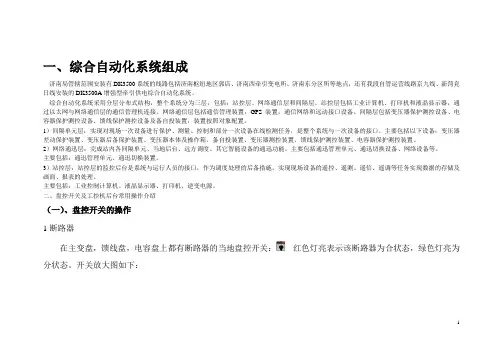
GL3520-22USB 3.0 Hub ControllerDatasheetRevision 1.07 Apr. 21, 2016CopyrightCopyright ©2016 Genesys Logic, Inc. All rights reserved. No part of the materials shall be reproduced in any form or by any means without prior written consent of Genesys Logic, Inc.Ownership and TitleGenesys Logic, Inc. owns and retains of its right, title and interest in and to all materials provided herein. Genesys Logic, Inc. reserves all rights, including, but not limited to, all patent rights, trademarks, copyrights and any other propriety rights. No license is granted hereunder.DisclaimerAll Materials are provided “as is”. Genesys Logic, Inc. makes no warranties, express, implied or otherwise, regarding their accuracy, merchantability, fitness for any particular purpose, and non-infringement of intellectual property. In no event shall Genesys Logic, Inc. be liable for any damages, including, without limitation, any direct, indirect, consequential, or incidental damages. The materials may contain errors or omissions. Genesys Logic, Inc. may make changes to the materials or to the products described herein at anytime without notice. Genesys Logic, Inc.12F., No. 205, Sec. 3, Beixin Rd., Xindian Dist. 231,New Taipei City, TaiwanTel :(886-2) 8913-1888Fax : (886-2) 6629-6168Revision HistoryTable of ContentsCHAPTER 1 GENERAL DESCRIPTION (7)CHAPTER 2 FEATURES (8)CHAPTER 3 PIN ASSIGNMENT (10)3.1 Pinout (10)3.2 Pin Descriptions (13)CHAPTER 4 FUNCTION DESCRIPTION (16)4.1 Block Diagram (16)4.2 General Description (17)4.2.1 USB 2.0 USPORT Transceiver (17)4.2.2 USB 3.0 USPORT Transceiver (17)4.2.3 PLL (Phase Lock Loop) (17)4.2.4 Regulator (17)4.2.5 SPI Engine (17)4.2.6 RAM/ROM/CPU (17)4.2.7 UTMI (USB 2.0 Transceiver Microcell Interface) (17)4.2.8 SIE (Serial Interface Engine) (17)4.2.9 Control/Status Register (17)4.2.10 Power Management Engine (17)4.2.11 Router/Aggregator Engine (18)4.2.12 REPEATER (18)4.2.13 TT (18)4.2.14 CDP Control Logic (19)4.2.15 USB 3.0/USB 2.0 DSPORT Transceiver (19)4.3 Configuration and I/O Settings (20)4.3.1 RESET Setting (20)4.3.2 PGANG Setting (21)4.3.3 SELF/BUS Power Setting (22)4.3.4 LED Connections (22)4.3.5 Power Switch (22)4.3.6 Port Number Configuration (22)4.3.7 Non-removable Port Configuration (22)CHAPTER 5BATTERY CHARGING SPECIFICATION REV.1.2 SUPPORT (23)5.1 Background (23)5.2 Standard Downstream Port (SDP) (23)5.3 Charging Downstream Port (CDP) (23)5.4 Dedicated Charging Port (DCP) (24)5.5 ACA-Dock (24)5.6 Apple and Samsung Devices (24)5.7 Port Numbers of Charging Downstream Port Configuration (24)CHAPTER 6 ELECTRICAL CHARACTERISTICS (25)6.1 Maximum Ratings (25)6.2 Operating Ranges (25)6.3 DC Characteristics (26)6.3.1 DC Characteristics except USB Signals (26)6.3.2 USB 2.0 Interface DC Characteristics (26)6.3.3 USB 3.0 Interface DC Characteristics (26)6.4 Power Consumption (27)6.5 On-Chip Power Regulator (28)6.6 External Clock (28)CHAPTER 7 PACKAGE DIMENSION (29)CHAPTER 8 ORDERING INFORMATION (31)List of FiguresFigure 3.1 - GL3520-22 QFN 88 Pin out Diagram (10)Figure 3.2 - GL3520-22 QFN64 (OS3) Pin out Diagram (Gang) (11)Figure 3.3 - GL3520-22 QFN64 (OS8) Pin out Diagram (Individual) (12)Figure 4.1 - Block Diagram (16)Figure 4.2 - Operating in USB 1.1 Schemes (18)Figure 4.3 - Operating in USB 2.0 Schemes (19)Figure 4.4 - Power on Reset Diagram (20)Figure 4.5 - Power on Sequence of GL3520-22 (20)Figure 4.6 - Timing of PGANG Strapping (21)Figure 4.7 - GANG Mode Setting (21)Figure 4.8 - SELF/BUS Power Setting (22)Figure 4.9 - LED Connection (22)Figure 6.1 - Vin(V5) vs Vout(V33)* (28)Figure 7.1 – GL3520-22 88 Pin QFN Package (29)Figure 7.2 – GL3520-22 64 Pin QFN Package (30)List of TablesTable 6.1 - Maximum Ratings (25)Table 6.2 - Operating Ranges (25)Table 6.3 - DC Characteristics except USB Signals (26)Table 8.1 - Ordering Information (31)CHAPTER 1 GENERAL DESCRIPTIONGenesys GL3520-22 is a 4-port, low-power, and configurable hub controller. It is compliant with the USB3.0 specification. GL3520-22 integrates Genesys Logic self-developed USB 3.0 Super Speed transmitter/receiver physical layer (PHY) and USB 2.0 High-Speed PHY. It supports Super Speed, Hi-Speed, and Full-Speed USB connections and is fully backward compatible to all USB 2.0 and USB 1.1 hosts. GL3520-22 also implements multiple TT* (Note1) architecture providing dedicated TT* to each downstream (DS) port, which guarantees Full-Speed(FS) data passing bandwidth when multiple FS devices perform heavy loading operations. Furthermore, GL3520-22 has built-in 5V to 3.3V regulator, which saves customers’ BOM cost, and eases for PCB design.GL3520-22 features the native fast-charging and complies with USB-IF battery charging specification rev1.2, it could fast-charge Apple, Samsung Galaxy devices, and any device complaint with BC1.2/1.1. It also allows portable devices to draw up to 1.5A from GL3520-22 charging downstream ports (CDP1) or dedicated charging port (DCP2). It can enable systems to fast charge handheld devices even during “Sleep”and “Power-off” modes. Available package: QFN88 (10x10 mm), QFN64 (8x8 mm). Summarize as below tableGL3520-22 Package – Feature Summary*Note: TT (transaction translator)implements the control logic defined in section 11.14 ~ 11.22 of USB specification revision 2.0. TT basically handles the unbalanced traffic speed between the USPORT (operating in HS) and DSPORTS (operating in FS/LS) of hub.1CDP, charging downstream port, the Battery Charging Rev.1.2-compliant USB port that does data communication and charges device up to 1.5A.2DCP, dedicated charging port, the Battery Charging Rev.1.2-compliant USB port that only charges devices up to 1.5A, similar to wall chargers.CHAPTER 2 FEATURES∙Compliant with USB Specification Revision 3.0-Upstream port supports super speed(SS) high speed(HS) and full speed(FS) traffic-Downstream ports support SS, HS, FS, and low speed(LS) traffic- 1 control pipe and 1 interrupt pipe-Backward compatible to USB specification Revision 2.0/1.1∙Featuring fast-charging on all downstream ports and upstream port-Compliant with USB Battery Charging Revision v1.2, supporting CDP, DCP, and ACA-Dock-Downstream ports can be turned from a Standard Downstream Port (SDP) into Charging Downstream Port (CDP) or Dedicated Charging Port (DCP)-Downstream devices can be charged while upstream VBUS is not present, which can be applied on wall charger applications-Upstream port is capable of charging and data communicating simultaneously for portable devices supporting ACA-Dock or proprietary charging protocols, such as Sony Z1 and ZL -Supporting Apple 2.4A and Samsung Galaxy devices fast-charging∙On-chip 8-bit micro-processor-RISC-like architecture-USB optimized instruction set- 1 cycle instruction execution (maximum)-Performance: 12 MIPS @ 12MHz (maximum)-With 256-byte RAM, 20K-byte internal ROM, and 20K-byte SRAM∙Multiple Transaction Translator(TT) architecture-Providing dedicated TT control logics for each downstream port-Superior performance when multiple FS devices operate concurrently∙Integrated USB transceiver-Improving output drivers with slew-rate control for EMI reduction-Internal power-fail detection for ESD recovery∙Advanced power management and low power consumption-Supporting USB3.0 U0/U1/U2/U3 power management states-Supporting USB Link Power Management (LPM) L0/L1/L2-Supporting individual/gang mode over-current detection for all downstream ports-Supporting low active power switch-Patented Smart Power Management∙Configurable settings by SPI-flash/EEPROM/pin strapping-Configurable charging port-Configurable 4/3/2 downstream ports-Configurable Poly-fuse/Power-switch-Supporting full in-system programming firmware upgrade by SPI-flash and EEPROM-Supporting compound-device (non-removable setting on downstream ports)-Supporting customization VID/PID∙Flexible design-Automatic switching between self-powered and bus-powered modes-Supporting PHY tuning-Supporting register setting by firmware-Supporting vendor command and SMBUS-Allow downstream ports to connect up to 8 devices, 4 x USB3.0 non-removable devices with 4 x USB2.0 non-removable devices or exposed ports∙Low BOM cost-Single external 25 MHz crystal / Oscillator clock input-Built-in upstream port 1.5KΩ pull-up and downstream port 15KΩ pull-down resistors-Built-in 5 to 3.3V regulator∙Available package type-QFN 88 (10x10mm)-QFN 64 (8x 8 mm)∙Applications-Standalone USB hub/Docking station-Tablet/Ultrabook/NB-Motherboard-Monitor built-in hub, GL3520-22 GPIOs can be programmed as I2C interface to easily update scalar firmware through USB interface-TV built-in hub-Compound device, such as hub-reader application-USB wall charger-Other consumer electronics-Customized applications▪Dynamically disable/enable ports▪GPIO signaling of ambient light sensor or rotation/position sensorCHAPTER 3 PIN ASSIGNMENT3.1 PinoutDVDD12VP12RXP_DS4RXN_DS4GNDTXP_DS4TXN_DS4VP12VP12RXP_DS3RXN_DS3GNDTXP_DS3TXN_DS3VP12VP12RXP_DS2RXN_DS2GNDTXP_DS2TXN_DS2VP12P A M B E R 4P W R E N 4J R T E R M N C N C X 1X 2N C T X N _U P T X P _U P G N D R X N _U P R X P _U P V P 12V P 12T X N _D S 1T X P _D S 1G N D R X N _D S 1R X P _D S 1V P 12N C A V D D 1D P 2D M 2A V D D D P 1D M 1D P 0D M 0D V D D D V D D 12P A M B E R 3V B U S O V C U R 4J P W R E N 1J P A M B E R 1P _S P I _C Z P _S P I _C K D V D D 12P G R E E N 3P W R E N 3J P W R E N 2J O V C U R 2JGND DM3DP3AVDD DM4DP4DVDD PGANG DVDD12TEST OVCUR3J OVCUR1J PGREEN1P_SPI_DO P_SPI_DI PSELF RESETJ PGREEN2V33V5PAMBER2PGREEN4GL3520Figure 3.1 - GL3520-22 QFN 88 Pin out DiagramDM3DP3AVDD DM4DP4DVDD PGANG DVDD12OVCUR1J P_SPI_DO P_SPI_DI PSELF RESETJ DVDD12V33V5R T E R MN CX 1X 2N CT X N _U PT X P _U PR X N _U PR X P _U PV P 12N CT X N _D S 1T X P _D S 1R X N _D S 1R X P _D S 1V P 12RXN_DS4TXP_DS4TXN_DS4NC VP12RXP_DS3RXN_DS3TXP_DS3TXN_DS3NC VP12RXP_DS2RXN_DS2TXP_DS2TXN_DS2NCA V D D 1D P 2D M 2A V D DD P 1D M 1D P 0D M 0D V D DD V D D 12V B U SP W R E N 1JP _S P I _C ZP _S P I _C KV P 12R X P _D S 4GL3520Figure 3.2 - GL3520-22 QFN64 (OS3) Pin out Diagram (Gang)AVDD1DM3DP3AVDD DM4DP4PGANG DVDD12TEST OVCUR3J OVCUR1J P_SPI_DO P_SPI_DI PSELF RESETJNCV 33V 5P W R E N 4JR T E R MX 1X 2T X N _U PT X P _U PR X N _U PR X P _U PV P 12T X N _D S 1T X P _D S 1R X N _D S 1R X P _D S 1V P 12OVCUR2J VP12RXP_DS4RXN_DS4TXP_DS4TXN_DS4VP12RXP_DS3RXN_DS3TXP_DS3TXN_DS3VP12RXP_DS2RXN_DS2TXP_DS2TXN_DS2D P 2D M 2A V D DD P 1D M 1D P 0D M 0D V D DV B U SO V C U R 4JP W R E N 1JP _S P I _C ZP _S P I _C KD V D D 12P W R E N 3JP W R E N 2JGL3520Figure 3.3 - GL3520-22 QFN64 (OS8) Pin out Diagram (Individual)3.2 Pin DescriptionsNote: Analog circuits are quite sensitive to power and ground noise. PCB layout must take care the power routing and the ground plane. For detailed information, please refer to USB 3.0 Hub Design Guide. Notation:Type O OutputI InputB Bi-directionalP Power / GroundA Analogpu Internal pull uppd Internal pull downCHAPTER 4 FUNCTION DESCRIPTION 4.1 Block DiagramFigure 4.1 - Block Diagram4.2 General Description4.2.1 USB 2.0 USPORT TransceiverUSB 2.0 USPORT (upstream port) transceiver is the analog circuit that supports both full-speed and high-speed electrical characteristics defined in chapter 7 of USB specification revision 2.0. USPORT transceiver will operate in full-speed electrical signaling when GL3520-22 is plugged into a 1.1 host/hub. USPORT transceiver will operate in high-speed electrical signaling when GL3520-22 is plugged into a 2.0 host/hub.4.2.2 USB 3.0 USPORT TransceiverUSB 3.0 USPORT (upstream port) transceiver is the analog circuit that has elastic buffer and supports receiver detection, data serialization and de-serialization. Besides, it has PIPE interface with SuperSpeed Link Layer4.2.3 PLL (Phase Lock Loop)PLL generates the clock sources for the whole chip. The generated clocks are proven quite accurate that help in generating high speed signal without jitter.4.2.4 RegulatorGL3520-22 build in internal regulator converts 5V input to 3.3V output.4.2.5 SPI EngineSPI engine is to move code from external flash to the internal RAM.4.2.6 RAM/ROM/CPUThe micro-processor unit of GL3520-22 is an 8-bit RISC processor with 16K-byte ROM and 256-bytes RAM. It operates at 12MIPS of 12 MHz clock( maximum) to decode the USB command issued from host and then prepares the data to respond to the host.4.2.7 UTMI (USB 2.0 Transceiver Microcell Interface)UTMI handles the low level USB protocol and signaling. It’s designed based on the Intel’s UTMI specification 1.01. The major functions of UTMI logic are to handle the data and clock recovery, NRZI encoding/decoding, Bit stuffing /de-stuffing, supporting USB 2.0 test modes, and serial/parallel conversion.4.2.8 SIE (Serial Interface Engine)SIE handles the USB protocol defined in chapter 8 of USB specification revision 2.0. It co-works with μC to play the role of the hub kernel. The main functions of SIE include the state machine of USB protocol flow, CRC check, PID error check, and timeout check. Unlike USB 1.1, bit stuffing/de-stuffing is implemented in UTMI, not in SIE.4.2.9 Control/Status RegisterControl/Status register is the interface register between hardware and firmware. This register contains the information necessary to control endpoint0 and endpoint1 pipelines. Through the firmware based architecture, GL3520-22 possesses higher flexibility to control the USB protocol easily and correctly.4.2.10 Power Management EngineThe power management of GL3520-22 is compliant with USB 3.0 specification. When operates in SuperSpeed mode, GL3520-22 supports U0, U1, U2 and U3 power states. U0 is the functional state. U1 and U2 are lower power states compared to U0. U1 is a low power state with fast exit to U0; U2 is a low power state which saves more power than U1, with slower exit to U0. U3 is suspend state, which is the most power-saving state, with tens of milliseconds exit to U0. Unlike USB 2.0, SuperSpeed packet traffic is unicast rather than broadcast. Packet only travels the direct path in-between host and the target device.SuperSpeed traffic will not reach an unrelated device. When enabled for U1/U2 entry, and there is no pending traffic within comparable exit latency, GL3520-22 will initiate U1/U2 entry to save the power. On the other hand, the link partner of GL3520-22 may also initiate U1/U2 entry. In this case, GL3520-22 will accept or reject low power state entry according to its internal condition.4.2.11 Router/Aggregator EngineRouter/Aggregator Engine implements the control logic defined in Ch10 of USB3.0 specification. Router/Aggregator Engine use smart method for route packet to device or aggregate packet to host.4.2.12 REPEATERRepeater logic implements the control logic defined in section 11.4 and section 11.7 of USB specification revision 2.0. REPEATER controls the traffic flow when upstream port and downstream port are signaling in the same speed. In addition, REPEATER will generate internal resume signal whenever a wakeup event is issued under the situation that hub is globally suspended.4.2.13 TTTT(Transaction Translator) implements the control logic defined in section 11.14 ~ 11.22 of USB specification revision 2.0. TT basically handles the unbalanced traffic speed between the USPORT (operating in HS) and DSPORTS (operating in FS/LS) of hub. GL3520-22 adopts multiple TT architecture to provide the most performance effective solution. Multiple TT provides control logics for each downstream port respectively.4.2.13.1 Connected to 1.1 Host/HubIf an USB 2.0 hub is connected to the downstream port of an USB 1.1 host/hub, it will operate in USB 1.1 mode. For an USB 1.1 hub, both upstream direction traffic and downstream direction traffic are passing through REPEATER. That is, the REPEATER/TT routing logic will route the traffic channel to the REPEATER.Figure 4.2 - Operating in USB 1.1 Schemes4.2.13.2 Connected to USB 2.0 Host/HubIf an USB 2.0 hub is connected to an USB 2.0 host/hub, it will operate in USB 2.0 mode. The upstream port signaling is in high speed with bandwidth of 480 Mbps under this environment. The traffic channel will then be routed to the REPEATER when the device connected to the downstream port is signaling also in high speed. On the other hand, the traffic channel will then be routed to TT when the device connected to the downstream port is signaling in full/low speed.Figure 4.3 - Operating in USB 2.0 Schemes4.2.14 CDP Control LogicCDP (charging downstream port) control logic implements the logic defined in USB Battery charging specification revision 1.2. The major function of it is to control DSPORT Transceiver to make handshake with a portable device which is compliant with USB Battery charging spec rev1.2 as well. After recognizing charging detection each other, portable device will draw up to 1.5A from VBUS to fast charge its battery. 4.2.15 USB 3.0/USB 2.0 DSPORT TransceiverDSPORT transceiver is the analog circuit that supports high-speed, full-speed, and low-speed electrical characteristics. In addition, each DSPORT transceiver accurately controls its own squelch level to detect the detachment and attachment of devices.4.3 Configuration and I/O Settings 4.3.1 RESET SettingGL3520-22’s power on reset can either be triggered by external reset or internal power good reset circuit. The external reset pin, RESETJ, is connected to upstream port Vbus (5V) to sense the USB plug / unplug or 5V voltage drop. The reset trigger voltage can be set by adjusting the value of resistor R1 and R2 (Suggested value refers to schematics) GL3520-22’s internal reset is designed to monitor silicon’s internal core power (1.2V) and initiate reset when unstable power event occurs. The power on sequence will start after the power good voltage has been met, and the reset will be released after approximately 40 μS after power good. GL3520-22’s reset circuit as depicted in the picture.GlobalReset#V BUS“Figure 4.4 - Power on Reset DiagramTo fully control the reset process of GL3520-22, we suggest the reset time applied in the external reset circuit should longer than that of the internal reset circuit. Timing of POR is illustrated as below figure.External resetVCC(3.3V) (1.2V)Figure 4.5 - Power on Sequence of GL3520-224.3.2 PGANG SettingTo save pin count, GL3520-22 uses the same pin to decide individual/gang mode as well as to output the suspend flag. The individual/gang mode is decided within 21us after power on reset. Then, about 50ms later, this pin is changed to output mode. GL3520-22 outputs the suspend flag once it is globally suspended. For individual mode, a pull low resister greater than 100KΩshould be placed. For gang mode, a greater than 100KΩpull high resister should be placed. In figure 4.7, we also depict the suspend LED indicator schematics. It should be noticed that the polarity of LED must be followed, otherwise the suspend current will be over spec limitation (2.5mA).Figure 4.6 - Timing of PGANG StrappingIndividualModeFigure 4.7 - GANG Mode Setting4.3.3 SELF/BUS Power Setting4.3.4 LED ConnectionsGL3520-22 controls the LED lighting according to the flow defined in section 11.5.3 of Universal Serial Bus Specification Revision2.0. Both manual mode and Automatic mode are supported in GL3520-22. WhenDGNDFigure 4.9 - LED Connection4.3.5 Power SwitchGL3520 supports low active power switch. Please refer to the reference schematic for power switch control.4.3.6 Port Number ConfigurationNumber of downstream port can be configured as 4/3/2 ports by firmware configuration, EEPROM, and pin strapping. Please refer to Genesys USB 3.0 Hub FW ISP Tool User Guide for the detailed setting information.4.3.7 Non-removable Port ConfigurationFor compound application or embedded system, downstream ports that always connect inside the system can be set as non-removable by firmware configuration, EEPROM, and pin strapping. Please refer to Genesys USB 3.0 Hub FW ISP Tool User Guide for the detailed setting information.CHAPTER 5 BATTERY CHARGING SPECIFICATION REV.1.2 SUPPORT5.1 BackgroundThe USB ports on personal computers are convenient places for portable devices to draw current for charging their batteries. This convenience has led to the creation of dedicated chargers that simply expose a USB standard-A receptacle. This allows portable devices to use the same USB cable to charge from either a PC or from a dedicated charger.If a portable device is attached to a USB host or hub, then the USB 2.0 specification requires that after connecting, a portable device must draw less than:∙ 2.5 mA average if the bus is suspended∙100 mA maximum if bus is not suspended and not configured∙500 mA maximum if bus is not suspended and configured for 500 mAIf a portable device is attached to a charging host or hub, it is allowed to draw a current up to 1.5A, regardless of suspend. In order for a portable device to determine how much current it is allowed to draw from an upstream USB port, the USB-IF Battery Charging specification defines the mechanisms that allow the portable device to distinguish between a USB standard host, hub or a USB charging host. Since portable devices can be attached to USB charging ports from various manufactures, it is important that all USB charging ports behave the same way. This specification also defines the requirements for a USB chargers and charging downstream ports.5.2 Standard Downstream Port (SDP)GL3520-22 complies with Battery Charging Specification rev1.2, which defines three charging ports: SDP, CDP and DCP. The SDP is a standard USB port which can transfer data and provide maximum 500mA current.5.3 Charging Downstream Port (CDP)GL3520-22 supports battery charging detection, turning its downstream port from a standard downstream port (SDP) into charging downstream port (CDP). GL3520-22 will make physical layer handshaking when a portable device that complies with BC rev1.2 attaches to its downstream port. After physical layer handshaking, a portable device is allowed to draw more current up to 1.5A.Once the charging downstream port of GL3520-22 is enabled, it will monitor the V DP_SRC on D+ line anytime. When a portable device, which is compliant with BC rev1.2, is attached to the downstream port, it will drive V DP_SRC on D+ line to initiate the handshake with charging downstream port. GL3520-22 will response on its D- line by V DM_SRC and keep in a certain period of time and voltage level. The portable device will accept this handshaking on its D- line in correct timing period and voltage level, and then turns off its V DP_SRC on D+ line. GL3520-22 will recognize that charging negotiation is finished by counting time between the portable device turning on and off its V DP_SRC. After that, the portable device can start to draw more current from VBUS to charge its battery more rapidly. It can draw current up to 1.5A.If there is no response from D- line, the portable device will recognize that it is attached to a standard downstream port, not a charging port.5.4 Dedicated Charging Port (DCP)GL3520-22 also supports dedicated charging port, which is a downstream port on a device that outputs power through a USB connector, but it is not capable of enumerating a downstream device. With the adequate system circuit design, GL3520-22 will turn its downstream port from a standard downstream port (SDP) into dedicated charging port (DCP), i.e short the D+ line to the D- line, to let the portable device draws current up to 1.5A. Please refer to the USB 3.0 Hub Design Guide document for the detailed information.5.5 ACA-DockAn ACA-Dock is a docking station that has one upstream port, and zero or more downstream ports. The upstream port can be attached to a portable device (PD), and is capable of sourcing ICDP to the PD, which means that the upstream port can charge and have data communication with the PD at the same time. Please refer to Battery Charging Spec v1.2 for more details.5.6 Apple and Samsung DevicesExcept BC rev1.2-complied portable devices, GL3520-22 also supports the fast charging of Apple and Samsung devices.- Apple: iPhone, iPad series.- Samsung: Galaxy Tab series, Galaxy Mobile Phones series.5.7 Port Numbers of Charging Downstream Port ConfigurationNumber of charging downstream port can be configured as 1/2/3/4 ports by firmware configuration. Please refer to the Genesys USB 3.0 Hub FW ISP Tool User Guide document for the detailed setting information.CHAPTER 6 ELECTRICAL CHARACTERISTICS 6.1 Maximum RatingsTable 6.1 - Maximum Ratings*Please refer to the reference design schematic.6.2 Operating RangesTable 6.2 - Operating Ranges6.3 DC Characteristics6.3.1 DC Characteristics except USB SignalsTable 6.3 - DC Characteristics except USB Signals* Schmitt trigger pads are VBUS, RESET6.3.2 USB 2.0 Interface DC CharacteristicsThe GL3520-22 conforms to DC characteristics for Universal Serial Bus specification rev. 2.0. Please refer to this specification for more information.6.3.3 USB 3.0 Interface DC CharacteristicsThe GL3520-22 conforms to DC characteristics for Universal Serial Bus specification rev.3.0. Please refer to this specification for more information.6.4 Power ConsumptionTest result represents silicon level operating current, without considering additional powerconsumption contributed by external over-current protection circuit such as power switch orpolyfuse. The power consumption measured by 5V is based on Genesys’ evaluation board. It maybe diverse with regulator power transfer efficiency and firmware configurations.6.5 On-Chip Power RegulatorGL3520-22 requires 3.3V source power for normal operation of internal core logic and USB physical layer (PHY). The integrated low-drop power regulator converts 5V power input from USB cable (Vbus) to 3.3V voltage for silicon power source. The 3.3V power output is guaranteed by an internal voltage reference circuit to prevent unstable 5V power compromise USB data integrity. The regulator’s maximum current loading is 250mA, which provides enough tolerance for normal GL3520-22 operation (below 100mA).On-chip Power Regulator Features: ● 5V to 3.3V low-drop power regulator● 250mA maximum output driving capability●Provide stable 3.3V output when Vin = 3.4V~5.5V ● 125uA maximum quiescent current (typical 80uA).Figure 6.1 - Vin(V5) vs Vout(V33)**Note: Measured environment: Ambient temperature = 25℃ / Current Loading = 250mA6.6 External ClockXOUT: 25MHz crystal oscillator output. It should be left open if an external clock source is used.XIN:25MHz crystal oscillator input. If an external 3.3V clock source is used, its frequency has to be 25MHz +/-300ppm with a peak-to-peak jitter less than 50ps.。
中国移动检测车研究报告中国移动检测车研究报告一、概述中国移动检测车是中国移动通信集团公司自主研发的一款移动通信网络质量监测设备。
该车配备了先进的测试仪器及设备,可以对移动通信网络进行全面的监测、诊断和分析,用于提升网络质量、优化网络结构和提供更好的通信服务。
二、技术参数1. 车辆参数:中国移动检测车采用了高性能的载重平台,车身宽敞稳定,可适应不同地形和路况。
2. 检测设备:中国移动检测车配备了各种各样的测试仪器和设备,包括无线网络测试设备、光纤测试设备、网络监控设备等。
这些设备可以实时监测网络质量、信号强度、传输速率等参数,并生成相应的测试报告。
3. 数据分析:中国移动检测车还配备了数据分析软件,可以对采集到的测试数据进行分析和处理,提供网络质量优化和网络结构优化的建议。
三、应用场景1. 网络问题排查:中国移动检测车可以快速定位和解决网络故障,提供精确的网络问题排查和诊断服务。
2. 网络优化:通过对移动通信网络进行全面的监测和分析,中国移动检测车能够提供网络优化的建议,帮助提升网络质量和用户体验。
3. 业务支持:中国移动检测车可以监测各种业务的质量,包括语音、短信、数据等,为移动通信网络的业务提供支持和改进。
四、成果与优势1. 提升网络质量:中国移动检测车通过实时监测和分析,能够及时发现和解决网络问题,帮助提升移动通信网络的质量。
2. 优化网络结构:中国移动检测车可以提供网络结构优化的建议,帮助改善网络的覆盖范围和容量,提升用户的满意度。
3. 改进用户体验:通过监测业务质量和提供相关建议,中国移动检测车可以改善用户的通信体验,提供更好的服务。
五、未来展望中国移动检测车将继续不断改进和升级,以适应移动通信网络技术的发展,并提供更加优质的服务。
相信在中国移动的努力下,中国移动检测车将为移动通信网络的建设和发展做出更大的贡献。
军用装备低温试验报告
一、试验目的
本试验旨在评估军用装备在低温环境下的性能表现,以确保其在极端温度条件下能够正常工作并满足作战需求。
二、试验设备与条件
1.试验设备:低温试验箱、军用装备样品、数据采集与分析系统
2.试验条件:低温范围:-40℃至-60℃;温度稳定时间:2小时;
测试时间:24小时
三、试验过程
1.将军用装备样品放置在低温试验箱内,确保装备处于正常工作
状态;
2.设定低温试验箱温度为-40℃、-50℃和-60℃,并保持2小时,使
装备充分适应低温环境;
3.在每个温度点下,对装备进行性能测试,记录各项性能参数;
4.观察装备在低温下的工作状态,记录异常情况;
5.持续测试24小时,评估装备的低温稳定性。
四、试验结果与分析
1.在-40℃、-50℃和-60℃下,军用装备的启动时间分别为x秒、y
秒和z秒,均满足技术要求;
2.在低温条件下,装备的各项性能参数表现稳定,未出现明显波
动;
3.在测试过程中,装备未出现工作异常、死机或性能下降等现象;
4.通过24小时持续测试,证明军用装备具有良好的低温稳定性。
五、结论
本试验表明,军用装备在低温条件下表现出良好的性能和工作稳定性,能够满足作战需求。
建议在后续使用中,加强装备的维护与保养,以保证其在各种环境下的稳定工作。
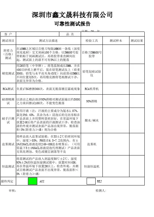
抗雾霾神器车载净化器车载测试报告
近日,雾霾问题再度成为公众关注热点。
雾霾中的主要成分PM2.5,这种
可吸入的微粒对健康造成威胁。
对于汽车的驾乘者来说,车内还有各种化学污
染物,如甲醛、甲苯,此时,PM2.5又会成为它们的载体,附着着各种有害物
质被吸入人体,产生更为严重的危害。
车载空气净化器市场再度火爆,而鱼龙混杂的市场销售,品种繁多的净化技术,令消费者应接不暇,陷入被动消费境地。
鉴于此,小编对市场上5款主流
品牌车载空气净化器:沃讯V9,飞利浦Compact200,3M-PN3880.夏普IG- BC2S-B和慑力H3S进行对比测试,为各位车主在选购车载空气净化器时提供
权威参考。
净化能力是关键
对PM2.5细微颗粒、甲醛/甲苯、TVOC等有害物质的实际净化效率是车载
空气净化器的核心功能,对这些有害物质的实际净化效率,也是鉴定一款车载
空气净化器是否有用的最重要指标。
此次测试过程中特别委托了上海市环保产
品质量监督检验总站进行了PM2.5细微颗粒、甲醛/甲苯、TVOC等有害物质
的实际净化效率进行检测。
以上检测参照GB/T18883-2002标准检测环境为1立方米。
在化学污染物去除率方面,飞利浦Compact200的成绩可以说是遥遥领先,
甲醛甲苯的净化率均超过其他品牌,TVOC的去除率更是超过了99%;同样作为国际品牌的3M,甲醛的净化效率为86%,而另外的3款产品基本对于化学污
染没有明显的去除效果。
在PM2.5颗粒净化效率方面,飞利浦Compact200和沃讯V9相比不相上下,3M产品虽然去除率也达到了92%,但是比起>99%的净化效能,还是稍显欠缺。
大众公司汽车部件EMC测试方案大众汽车电子零部件emc预测试解决方案从大众汽车标准的分析来看,大众汽车在emc测试中,基本使用gspr25、iso11452、iso7637、iso10605。
下表列出主要对应关系:大众标准tl965国际标准cispr25采用方案传导滋扰人工电源网络tem小室整车电波暗室频率范围/选件150khz-108mhz150khz-200mhz70khz-2500mhz附注最好采用半电波暗室,tem小室上限频率只有200mhz最出色能顺利完成12v,24v,42v供电的测试自由选择一种女团全面覆盖1m-1000mhz,本方案中使用bci协调半电波暗室iso7637-3采用耦合钳阻抗试验配置同tl82066tl82166iso7637-2iso11452传导暂态阻碍测量暂态阻碍抗扰度iso11452-2iso11452-3iso11452-4iso11452-5半电波暗室80m-1000mtem小室1-400mbci1-1000m带状线1-400m1m-400m3a与3b波形协调耦合钳子协调电阻电容模块tl82366tl82466传感器电缆与掌控电iso11452-4缆测试iso7637-3iec61000-4-2静电振动iso10605r=330ω,r=2000ω,iecc61000-4-2估计很c=330pf,c=150pf快会采用iso10605根据上述分析,用户可以使用两种方案:一种为有电波暗室的方案,这种方案是最佳考虑,如果只做元器件测试,7×3×3(m3)的电波暗室就可以完全满足预测试的要求另一种,不使用电波暗室,但频率范围受到限制,满足用户初期预测先行须要,在这种现象中,不须要测量天线及电波暗室,但是在系统结果比对,实验结果的重复,这里不提供更多这类非电波暗室布局。
用户可以精简在电波暗室中的测试,自行布局,布局中须要在电波暗室中顺利完成的项目以篮色字体标示出。
大华产品检测报告1. 引言在现代社会,技术的快速发展和普及使得各种产品在市场上层出不穷。
然而,为了确保产品的质量和可靠性,对这些产品进行检测是非常重要的。
本报告旨在对大华公司的产品进行全面的检测,评估其性能和质量。
2. 检测目的本次检测旨在评估大华公司生产的产品的质量和性能,以确保其符合国家和行业标准。
通过对产品进行全面的检测,我们可以更好地了解其可靠性、稳定性和耐用性,以及是否存在任何安全隐患。
3. 检测方法3.1 产品外观检测:通过对产品外观进行详细检查,评估其外观质量和加工工艺。
包括产品的外部结构、表面涂层、标识等方面的检测。
3.2 功能性能检测:通过对产品的各项功能进行测试,评估其性能是否符合规定要求。
包括产品的传感器、控制系统、通讯功能等方面的检测。
3.3 可靠性测试:通过对产品在长时间使用或恶劣环境下的运行测试,评估其可靠性和稳定性。
包括产品的耐用性、温度适应性、防水性能等方面的测试。
3.4 安全性评估:通过对产品的安全性能进行评估,确保产品在正常使用过程中不会对用户造成伤害。
包括产品的电气安全、防火性能、电磁兼容性等方面的评估。
4. 检测结果4.1 外观检测结果:大华公司的产品外观质量较好,加工工艺精细。
产品表面涂层均匀,标识清晰可辨。
4.2 功能性能检测结果:大华公司的产品功能性能符合规定要求。
传感器反应灵敏,控制系统运行稳定,通讯功能正常。
4.3 可靠性测试结果:大华公司的产品在长时间使用和恶劣环境下的运行测试中表现良好。
产品耐用性较高,温度适应性强,防水性能可靠。
4.4 安全性评估结果:大华公司的产品通过了安全性评估。
产品的电气安全符合标准要求,防火性能良好,电磁兼容性合格。
5. 结论通过本次检测,我们得出以下结论:5.1 大华公司的产品外观质量好,加工工艺精细。
5.2 大华公司的产品功能性能符合规定要求。
5.3 大华公司的产品具有较高的可靠性和稳定性。
5.4 大华公司的产品安全性能良好,能够保证用户的使用安全。
铝箔软管检测报告
铝箔软管检测范围
遮光铝箔,铝箔袋,亲水铝箔,高压铝箔,铝箔伸缩软管,铝箔胶带,铝箔封口等。
铝箔软管检测项目
质量检测,强度检测,老化检测,阻菌性,防火性能检测,易氧化物检测,微生物检测,reach检测等。
铝箔软管检测标准
1GB/T 3615-2016电解电容器用铝箔
2GB/T 22638.1-2016铝箔试验方法第1部分: 厚度的测定
3GB/T 22638.2-2016铝箔试验方法第2部分:针孔的检测
4GB/T 22638.3-2016铝箔试验方法第3部分:粘附性的检测5GB/T 22638.4-2016铝箔试验方法第4部分:表面润湿张力的测定
6GB/T 22638.5-2016铝箔试验方法第5部分:润湿性的检测7GB/T 22638.6-2016铝箔试验方法第6部分:直流电阻的测定
8GB/T 22638.7-2016铝箔试验方法第7部分:热封强度的测定
9GB/T 22638.8-2016铝箔试验方法第8部分:立方面织构含量的测定
10GB/T 22638.9-2016铝箔试验方法第9部分:亲水性的检测
11GB/T 22638.10-2016铝箔试验方法第10部分:涂层表面密度的测定
12GB/T 22642-2008电子、电力电容器用铝箔
13GB/T 26492.4-2011变形铝及铝合金铸锭及加工产品缺陷第4部分:铝箔缺陷
14GB/T 28118-2011食品包装用塑料与铝箔复合膜、袋
15GB/T 31942-2015金属蜂窝载体用铁铬铝箔材。
2015年分组微波设备采购项目现场测试报告(京信)中国移动通信集团湖南有限公司2015年4月目录1前言 (3)1.1测试规范(重要) (3)1.2测试仪表 (3)1.3测试条目 (3)2测试项目 (4)2.1空口容量(吞吐量) (4)2.2吞吐量测试(帧头压缩) (6)2.3丢包率 (7)2.4发射功率测试 (9)2.5与PTN组网保护倒换测试(不测) (9)2.6时延测试 (10)2.7以太网、E1业务测试及业务配置无损伤动态容量分配测试 (13)2.8AM自适应模式调整(参考) (13)3其他要求.................................................................................................. 错误!未定义书签。
3.1样品送货及时性 ........................................................................... 错误!未定义书签。
3.2安装调试的简便性 ....................................................................... 错误!未定义书签。
1 前言1.1 测试规范(重要)●在一个测试项目开始测试之前,记录设备版本信息,测试期间版本不做更改。
●测试过程按步骤执行,任何反馈都应被记录。
●被测系统初始化后,应尽量通过网管系统进行配置操作。
●不可见的激光辐射对无防护的肉眼有害。
为保障个人眼部安全,请在使用有激光发射功能设备时,避免直视激光发射接口或使用特定设备对眼部进行保护。
1.2 测试仪表1.3 测试条目PTN微波测试条目是依据中国移动分组数字微波通信设备测试规范要求,针对PTN微波制定的测试条目。
该条目包括微波链路功能测试,以太性能指标测试以及以太网QoS测试等。
基于Hi3520D的车载监控系统设计与实现邵泽靖;胡静;宋铁成;黄秦【摘要】结合车载视频监控发展实际情况,文章设计了一种基于Hi3520D的车载监控视频终端.使用基于嵌入式Linux操作系统的Hi3520D作为核心芯片,通过NVP6114采集视频,并将车载终端作为流媒体服务器.远程监控客户端通过网络访问终端查看监控视频.实验表明,该终端可实现视频采集并能稳定运行,本地WiFi测试播放速率达25帧/s.【期刊名称】《无线互联科技》【年(卷),期】2018(015)019【总页数】5页(P131-134,137)【关键词】Hi3520D;NVP6114;视频监控;流媒体服务器【作者】邵泽靖;胡静;宋铁成;黄秦【作者单位】东南大学信息科学与工程学院,江苏南京 210096;东南大学信息科学与工程学院,江苏南京 210096;东南大学信息科学与工程学院,江苏南京210096;东南大学信息科学与工程学院,江苏南京 210096【正文语种】中文随着社会经济的发展,交通运输业成为国民经济发展重要经济命脉。
移动通信技术的发展,为物联网技术提供了强有力的支持,在交通运输行业催生了车联网这一概念。
车联网概念引申自物联网(Internet of Things,IoT)。
行业背景不同,对车联网的定义也不相同。
传统的车联网定义是指装载在车辆上的电子标签,通过无线射频等识别技术实现在信息网络平台上,对所有车辆的属性信息和静、动态信息进行提取和有效利用。
根据不同的功能需求,对所有车辆的运行状态,进行有效的监管并提供综合服务的系统。
车载视频监控是车联网领域的一个重要研究课题,它能方便用户实时、直观地监控车辆安全情况[1]。
为了更有效地对车辆情况进行监管,本设计使用Hi3520D作为车载终端核心芯片,基于Linux嵌入式进行程序设计,实现采集、显示、存储视频数据功能,将车载终端作为流媒体服务器,供远程视频监控软件查看视频终端内的视频文件。