无损金属磁记忆检测技术试验研究方法
- 格式:pdf
- 大小:599.94 KB
- 文档页数:10

1 .什么叫磁记忆效应?在具有外磁场(地球磁场)存在的条件下,承载的铁磁部件中会产生应力集中,并在应力集中部位出现导磁率减小,工件表面的漏磁场增大的现象,铁磁性金属部件所具有的这一特性称之为“磁机械效应”。
由于这一增强了的磁场“记忆”着部件的缺陷或应力集中的位置,故又称“磁记忆”效应。
2 .什么叫金属磁记忆检测?金属的磁记忆检测(M MT )是利用金属磁记忆效应来检测部件应力集中部位的一种快速无损检测方法。
该方法对铁磁性部件由于疲劳、形变、损伤而产生的微裂纹可进行早期诊断。
3 .简述磁记忆检测的原理。
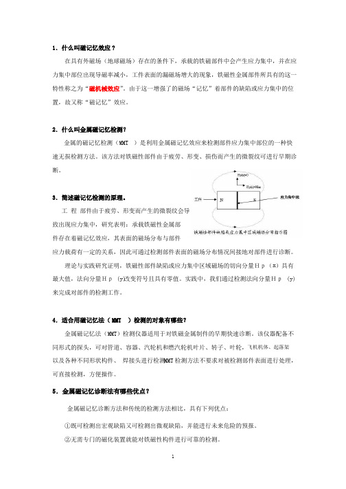
工程部件由于疲劳、形变而产生的微裂纹会导致出现应力集中,研究表明:承载铁磁性金属部件存在着磁记忆效应,其表面的磁场分布与部件应力载荷有一定的关系,因此可通过检测部件表面的磁场分布情况间接地对部件进行诊断。
x 理论与实践研究证明,铁磁性部件缺陷或应力集中区域磁场的切向分量Hp()具有最大值,法向分量Hp(y) 改变符号且具有零值。
实践中,我们通过检测法向分量Hp (y) 来完成对部件的检测工作。
4 .适合用磁记忆法(MMT )检测的对象有哪些?金属磁记忆法(M MT )检测仪器适用于对铁磁金属制件的早期快速诊断。
该仪器配备不同形式的探头,可对管道、容器、汽轮机和燃汽轮机叶片、转子、叶轮,飞机机体、起落架以及各种不同形状构件、焊接头进行检测。
MMT 检测方法不要求对被检测部件表面进行处理,可直接检测,方便操作。
5 .金属磁记忆诊断法有哪些优点?金属磁记忆诊断方法和传统的检测方法相比,具有下列优点:①既可检测出宏观缺陷又可检测出微观缺陷,并能进行未来危险的预报。
②无需专门的磁化装置就能对铁磁性构件进行可靠的检测。
③不需对被检金属表面进行清理或其它预处理。
④提离效应影响很小。
⑤设备轻便、自带电源、有记录装置,操作简单、灵敏度高、重复性与可靠性好。
⑥在检测过程中确定零件的应力集中线,实现早期诊断。
6 .简述《磁记忆检测数据分析软件》的用途。

金属磁记忆检测技术机理、概况及应用2006年6月2日摘要:介绍金属磁记忆检测技术的机理、发展、现状、目的和意义,用一个应用实例初步评价了磁记忆检测技术的有效性,提出了磁记忆技术发展的近期和远期目标,展望了应用前景。
金属磁记忆检测技术可以准确可靠地探测出铁磁构件以应力集中为特征的危险部位,是迄今为止对金属构件进行早期诊断的唯一可行的无损检测方法。
金属磁记忆检测法利用处于地球磁场中的铁磁性金属的磁性能在应力和变形集中区内产生不可逆变化,在金属与空气边界出现磁导率跃变,其表面产生漏磁场,测试该漏磁场便可无损、快速、便捷、准确地确定铁磁性金属结构上的应力和变形集中区即设备上最危险的区段和部位,进行强度和寿命的诊断。
这种技术弥补了传统无损检测方法的不足,具有以下显著的特点,①是一种能以高准确度确定检测对象上以应力和变形集中区为标志的最危险区域的唯一无损检测方法,可以通过早期诊断较为准确地评价设备的安全性。
②对设备外露部分的检测无需设备停止工作。
③无需对被检测对象表面进行去除涂层、打磨等预处理,降低了成本。
④原理可靠,特征信号明显,去除人为因素,结果准确性高。
⑤能够实现快速检测 (1OOm/h)和检测自动化,以便对设备进行 i00 快速扫查,提高效率,避免漏检。
⑥利用地球磁场,无需专门的磁化装置,从而使检测设备体积小、重量轻、成本低,同时能改善劳动条件,降低劳动强度。
金属磁记忆检测技术的机理磁记忆原理可以表述为:处于地磁环境下的铁构件受工作载荷的作用,其内部会发生具有磁致伸缩性质的磁畴组织定向的和不可逆的重新取向,并在应力与变形集中区形成最大的漏磁场 H的变化。
即磁场的切向分量 H (z)具有最大值.而法向分量 H (y)改变符号且具有零值点。
这种磁状态的不可逆变化在工作载荷消除后继续保留。
从而通过漏磁场法向分量 H (y)的测定,便可准确推断工件的应力集中部位。
磁记忆检测原理可以由拉伸试验得到验证。
研究证明,产生金属磁记忆的原理是磁弹性效应。

华中科技大学硕士学位论文金属磁记忆检测方法及试验研究姓名:王欢申请学位级别:硕士专业:机械电子工程指导教师:康宜华;武新军20050429摘 要设备的零部件和金属构件发生的损坏,80%是由于各种微观和宏观机械应力集中所导致的疲劳失效。
金属磁记忆检测方法可以实现对铁磁性构件应力集中损伤的早期诊断,对防止突发性的疲劳损伤事故具有非常重要的意义。
本文首先总结了铁磁性构件的各种应力检测方法,对比了国内外的相关研究现状,且从铁磁性材料的磁化理论和基本现象出发研究了磁记忆检测的原理,并在此基础上介绍了用于本课题试验研究的磁记忆检测系统;然后根据金属磁记忆检测原理可以由拉伸试验得到验证的理论,预制了一批钢棒试件进行静拉伸试验过程中的磁记忆信号分布变化与应力场关系的初步定性研究,总结其磁记忆现象的特点,并通过试验分析了磁记忆检测的影响因素;由于钢丝绳受力和结构制造等的复杂性其疲劳检测一直以来很难开展,最后建立了模拟钢丝绳的实际工作状态的试验装置,尝试检测三个不同工作段疲劳循环过程中的磁记忆信号,通过MATLAB软件进行去噪处理后进行分析比较,得到钢丝绳疲劳循环过程中的磁记忆现象的特点。
通过试验可以发现,磁记忆检测根据磁性的变化来判断应力集中和缺陷的存在,大部分零值点和磁场畸变处均对应了应力集中和缺陷。
因此,作为一种新的无损检测方法,无论从理论上还是实践中都是切实可行的。
关键词:铁磁性磁记忆检测应力集中动疲劳静拉伸 MATLABAbstractThe fatigue invalidation made by the kind of microcosmic and macroscopical mechanical stress concentrate 80% resulted in equipment part and metal components damage. The metal magnetic memory testing method can diagnose stress concentrate zone of the ferromagnetic which the damage is going to appear in advance, thus realize to predict destruction. So it is very important to avoid the unplanned fatigue failure.First, the thesis expounded the kind of stress testing of ferromagnetic part and the current developing status around the world, the devise of metal magnetic memory testing system was introduced basing on the elements of metal magnetic memory testing being studied from the quest for the magnetization theory and basic phenomenon of ferromagnetic material. Second, according to the theory of magnetic memory testing can be validated by tension experiment, a passel of steal bar had been made to primary discuss the relation of magnetic signal distributing and stress field under static tension experiment, then summarized the characteristic of magnetic memory phenomenon during the static tension course and analyzed the influencing factor. Finally, because wire ropes fatigue testing is very hard to develop for its characteristic of being forced and construct, so experiment equipment simulating wire ropes actual working estate was been set up to test the magnetic memory signal distributing of three inspected segment during the fatigue circling course at last, the yawp of signal is been eliminated by MATLAB, then attained the characteristic of magnetic memory phenomenon during the circling course by analyzing and comparing the signal .We can find that stress concentrate and flaw can be judged basing the change of their magnetism with metal magnetic memory testing by analyzing the signal, much of point of zero and exception magnetic field is corresponding to them. So metal magnetic memory testing is feasible from theory and practice as a new non-destructive testing.Keywords: ferromagnetic magnetic memory testing stress concentrate dynamic fatigue static tension MATLAB√独创性声明本人声明所呈交的学位论文是我个人在导师的指导下进行的研究工作及取得的研究成果。
金属磁记忆检测技术研究1金属磁记忆检测技术金属磁记忆检测技术是上世纪俄罗斯杜波夫教授提出的一种新型无损检测技术,其基本原理是记录在工作载荷作用下铁磁性构件局部应力集中区域中产生的漏磁场,根据漏磁场来判断应力集中及损伤。
机械零部件和金属构件发生损坏的主要根源是各种微观和宏观机械应力集中,在应力集中区域,腐蚀、疲劳和蠕变过程的发展最为激烈。
机械应力同铁磁材料的自磁化现象和残磁状况有着直接的联系。
在地磁作用的条件下,铁磁性构件缺陷处的导磁率减小,工件表面的漏磁场增大,称为铁磁性材料的磁机械效应。
该效应可增强铁磁性构件的表面磁场,增强的磁场“记忆”着部件缺陷或应力集中位置,称为金属的“磁记忆”效应。
理论和试验均表明,金属构件的损坏与其先天的“遗传”特性和后天的在役工作负荷相关,在缺陷的发生、发展过程中,应力集中是根源,是构件损坏的早期表现。
工程部件因为疲劳、蠕变而产生的微裂纹会导致缺陷处出现应力集中。
试验研究表明:铁磁性金属部件存有着磁机械效应,其表面上的磁场分布与部件应力载荷有一定的关系。
铁磁性部件缺陷或应力集中区域磁场的切向分量Hp(x)具有最大值,法向分量Hp(y)改变符号且具有零值,如图1所示。
金属磁记忆检测技术具有以下显著的特点:①既可检测出宏观缺陷,又可检测出微观缺陷,并进行未来危险预报,准确度高,可通过早期诊断对设备的安全性进行准确评价;②无需专门的磁化装置就能对铁磁性构件进行可靠检测;③提离效应影响小;④无需去除被检测对象表面涂层,就能检测橡胶等蒙皮下的缺陷;⑤无需对被测设备进行清洗、打磨等表面预处理,检测方便,成本低;⑥无需系统、专业的培训,原理可靠,特征信号明显,判据简单;⑦检测快速,能够实现快速检测(100m/h),效率高;⑧检测设备体积小、重量轻,便于携带,可实现单人作业;⑨对设备外露部分检测时,无需设备停机。
在实际应用中,金属磁记忆检测技术可通过检测部件表面的磁场分布情况间接地对部件缺陷或应力集中位置进行诊断。
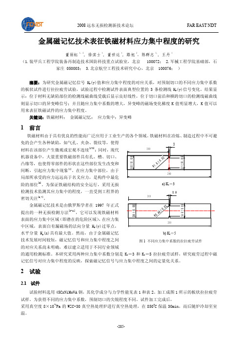
金属磁记忆技术表征铁磁材料应力集中程度的研究董丽虹1,2, 徐滨士1, 董世运1, 路旭2,陈群志3,, 王丹1(1.装甲兵工程学院装备再制造技术国防科技重点试验室,北京 100072; 2.军械工程学院基础部,石家庄 050003; 3.北京航空工程技术研究中心,北京 100076; )摘要:为研究金属磁记忆信号H p (y)值和应力集中程度的对应关系,对预制切口的不同应力集中系数的板状试件进行拉拉疲劳试验,试验过程中检测试件表面典型位置的3条检测线H p (y)信号变化。
结果显示:位于材料无缺陷部位的检测线磁曲线受载后显示良好线性,位于切口前沿和横跨切口的检测线磁曲线则显示切口的异变峰信号;并且随应力集中系数的增大,异变峰的磁场变化梯度K 值明显增大,K 值可以用来表征铁磁试件的应力集中程度。
关键词:铁磁材料; 金属磁记忆; 应力集中;异变峰1 前言铁磁材料由于具有优良的性能而广泛应用于工业生产的各个领域。
铁磁材料在冶炼、制造过程中不可避免的会产生各种缺陷,如气孔、夹杂、裂纹等,使得材料在该部位产生微观或宏观不连续[1-3];同时,现代机器设备中,大量重要铁磁部件具有孔、槽、切口、凸缘等,也使得零部件的形状在这些部位发生改变和间断,引起应力集中现象[4]。
在应力集中部位,由于局部所承受的应力远远高于名义应力,是构件中最危险的部位[5]。
为保证铁磁结构的安全运行,采用无损检测技术监测其应力集中的程度,一直受到工程界的密切关注[6,7]。
金属磁记忆技术是由俄罗斯学者在1997年正式提出的一种无损检测方法[8-11],它可以发现铁磁材料表面的应力集中区域(即潜在的危险区域),在应力集中区域,表面自有漏磁场的法向分量H p (y)过零点,水平分量H p (x)具有最大值。
然而,由于金属磁记忆技术发展时间较短,磁记忆信号和应力集中程度之间的对应关系尚未明确,难以建立适用于不同行业领域的通用检测标准。
本研究采用两种应力集中系数分别是K t =3和K t =5拉拉疲劳试样,研究疲劳过程中磁记忆信号对应力集中程度的反映,探索磁记忆信号与应力集中程度之间的定量化关系。


第28卷 第5期2008年10月 航 空 材 料 学 报JOURNAL OF AERONAUTI CA L MATER I ALSVol 128,No 15 Oct obe r 2008磁记忆检测力2磁效应微观机理的试验研究任吉林1, 陈 晨1, 刘昌奎2, 陈 曦1, 舒铭航1, 陈 星1,2(1.南昌航空大学无损检测技术教育部重点实验室,南昌330063;2.北京航空材料研究院中国航空工业失效分析中心,北京100095)摘要:铁磁材料在地磁场环境中受载荷的作用,其内部会发生具有磁致伸缩性质的磁畴组织定向和不可逆的重新取向。
将去应力退火后的20钢和45钢压缩试件分别施加不同载荷并制作成金相观察试样,利用粉纹法观察受力程度不同的试件的磁畴结构,然后,对比同种材料不同载荷试样的磁畴结构照,分析不同残余应力对磁畴的影响。
试验表明:未受力或应力集中较小时,晶粒内磁畴以片状畴为主,同一晶粒内畴壁相互平行,随着应力集中程度的增加,磁畴结构出现迷宫畴。
且应力集中程度越大,迷宫畴个数越多,同时畴壁长度和间距发生改变。
关键词:金属磁记忆;磁畴;畴壁;迷宫畴;片状畴中图分类号:T G142177 文献标识码:A 文章编号:100525053(2008)0520041204收稿日期:2008203224;修订日期:2008206227基金项目:教育部无损检测技术重点实验室开放基金(Z D200729012);江西省教育厅重点实验室重点课题(06-3);国防科技工业基础科研项目(636)作者简介任吉林(5—),男,教授,(2)j @1。
金属磁记忆检测是一种新的无损检测方法,它利用受载铁磁构件的磁记忆信号可以确定在被测对象上以应力集中为特征的危险部位,从而被认为是迄今为止,唯一能够对铁磁部件的损伤进行早期诊断的无损检测方法。
其基本原理是由于金属内部存在着多种内耗效应(如粘弹性内耗、位错内耗等),造成在动态载荷消除之后,加载时在金属内部形成的应力集中区得以保留。
21世纪ND T 新技术——金属磁记忆诊断法21st Cen tu ry 2O rien ted N ondestructive T esting T echno logy ——M agneticM em o ry M etal D iagno stic T echn ique爱德森电子有限公司(福建厦门361001) 林俊明摘 要:传统的无损检测方法(超声、射线、涡流、磁粉、渗透、着色等)只能检测出业已出现的缺陷,不能解决在役金属构件意外疲劳损伤的问题。
而疲劳损伤的发展和破坏性往往与应力集中密切有关。
金属磁记忆诊断技术能利用应力集中区漏磁场改变的特点,通过对工件表面漏磁场法向分量的扫描,实现对金属早期损伤的诊断。
为此介绍E M S 22000智能化磁记忆金属诊断仪的工作原理、特性和应用。
关键词:磁记忆;故障早期诊断;无损检测中图分类号:T G 115127+2文献标识码:A文章编号:100329171(2000)0920044202利用铁磁性部件缺陷在外部强磁场作用下产生漏磁的现象来检测部件缺陷的漏磁检测法,已作为常规检测技术应用于各种铁磁性部件的质量检验中。
其作用机理是缺陷在强磁场作用下・被・动・地产生・磁・泄・漏,从而让磁敏元件・方・便・地逮着,进而判断其缺陷的大小以及性质等。
这种方法必须采用笨重的磁化设备,且耗能大,检测过后往往需要对部件进行退磁。
对一些在役设备、部件,或者复杂结构的部件,常规漏磁法往往难以实施。
众所周知,地磁在人们生活的空间中几乎无所不在。
任何铁磁性设备、部件,同样也处在地磁的包围之中,因此也会被地磁磁化。
通常,人们未觉察到铁磁性部件的“磁性”,并非是不存在“磁性”,而是其磁性强度较弱罢了。
事实上,在役部件在周期性或振动性负载条件下,由于磁弹性和磁机械效应的作用,金属磁化强度将显著增加。
第二世界大战期间,俄国军舰遭到德国磁性水雷的破坏,亚历山大罗夫院士等俄国科学家就专门解释了这样一种现象,即在振动负载作用下,处于地球磁场中的军舰壳体金属磁化率增长的原因。
用金属磁记忆法测评焊接接头质量李衍(无锡锅炉压力容器学会无损检测专委会,江苏无锡214026)摘要:介绍用金属磁记忆(MMM)效应,测评承压设备焊接接头质量的新方法。
此法已在我国电力工业上成功应用。
MMM法是基于自漏磁场(SMLF)分布分析的无损检测(NDT)法,自漏磁场是在焊接和设备运行期间自然形成的。
SMLF读数能以快检方式完整测评实际焊接状态,因其含结构力学不均匀性、残余应力分布和焊接缺陷等信息。
施检前,焊缝金属表面一般无需清理。
这里给出了对不同类型、尺寸的管道焊接接头,用MMM法和常规NDT 法(RT、UT)检测的案例,比照了检测结果,意在为推广MMM技术在承压设备在制在用检测上的应用,抛砖引玉。
关键词:金属磁记忆(MMM);自漏磁场;应力集中区;焊接质量测评1.金属磁记忆检测概述1.1现状和问题各种焊接接头质量现代无损检测(NDT)一个重要而复杂的问题,是搜索和探测成套复杂系统中的“薄弱环节”一括结构力学不均匀性、焊接缺陷、结构和过程应力集中体,即高应力应变状态异质区或应力集中区(SCZ)。
这对焊接接头的制作、焊后直接生产、工艺流程的优化及产品的运行都很重要。
焊接在世界上已有100多年历史,但长期以来,因缺乏适于广泛实用的NDT方法,要诊断影响焊接接头可靠性的至要因素,即测评残余焊接应力分布,一直未妥善解决。
传统的缺陷检测方法只针对焊接接头的不连续性缺陷进行检测,不能保证对焊接接头质量作真实评价。
焊接工程技术人员单凭探伤结果难以揭示焊接缺陷产生原因,难以改进焊接工艺。
在焊接接头可靠性受多种因素影响的情况下,就很需要一种能综合评价焊接接头金属状态的NDT方法。
1.2MMM新法利用金属磁记忆(MMM)效应,开发了产品和焊接接头金属诊断的新方法。
首创国是俄罗斯(上世纪90年代中期),首创者是A.A. Dubov教授(莫斯科动力诊断公司)。
目前,此法已在俄罗斯和其他国家多种工业上成功应用。
9年前,我国国家能源局也已发布了DL/T 370-2010等三个系列标准,为承压设备焊接接头MMM检测提供技术支撑。

研究金属磁性的实验方法及数据分析技巧近年来,随着人们对材料科学的不断深入研究,金属磁性作为一种重要的物性研究方向备受关注。
金属磁性的实验方法以及数据分析技巧,对于我们深入了解金属材料的本质特性具有重要意义。
首先,研究金属磁性的实验方法是我们了解金属磁性本质的基础。
最常见的方法是通过磁化曲线的测量和分析。
磁化曲线是指对材料施加不同磁场强度后,测量其磁化强度的曲线。
该实验常用的装置是霍尔差分法、霍尔效应法以及磁力计法。
实验中,首先将金属样品放置在所选定的磁场中,记录施加不同磁场强度时的磁感应强度,并绘制磁化曲线。
通过对磁化曲线的分析,我们可以得到材料的磁滞回线、剩余磁场等参数,进而了解金属磁性的性质。
其次,数据分析技巧在研究金属磁性中扮演着重要角色。
数据分析技巧可以帮助我们理解实验结果,发现隐藏在海量数据背后的意义。
例如,在研究金属磁性时,我们常常需要将实验数据进行拟合。
拟合是一种将实验结果与理论模型进行对比的方法,通过优化拟合参数,提高数据与模型的拟合度。
常见的拟合方法包括线性拟合、非线性拟合和曲线拟合等。
通过拟合技巧,我们可以找到合适的模型来解释实验数据,并进一步验证我们对金属磁性的理解和假设。
此外,为了更准确地进行研究,我们还需要考虑材料的结构和成分对磁性的影响。
例如,金属的晶格结构、晶体缺陷以及杂质掺杂等因素都会对磁性产生影响。
因此,在实验中,我们需要研究金属样品的微观结构,并进行相关分析。
最常见的方法是通过X射线衍射、透射电子显微镜(TEM)等技术来观察金属的晶体结构以及晶界的特点。
通过这些观察,我们可以建立起磁性和材料微观结构之间的关系。
最后,要想深入研究金属磁性,还需要借助计算方法。
计算方法可以通过建立理论模型,利用电子结构计算和磁力学模拟等手段来研究材料的磁性。
通过计算方法,我们可以预测材料的磁性行为以及反应机理,为实验提供有针对性的指导。
综上所述,研究金属磁性的实验方法及数据分析技巧对于我们深入了解物质的磁性行为具有重要意义。

《》2010年第2期摘要:检测系统由霍尼韦尔HMC1021传感器、信号调理电路、单片机、4-20mA 电流变送器、上位机构成。
文章设计了新颖的检测装置结构,在软件中自动置位———复位设计可消除传感器上历史磁场的影响,提高了传感器的测量精度。
实验表明:金属磁记忆检测方法可以有效检测钢丝绳的损伤,对于防止事故发生具有重要的现实意义。
关键词:金属磁记忆;钢丝绳;无损检测中图分类号:TP277文献标识码:A文章编号:1672-0547(2010)02-0079-021.引言索道具备旅游、观光、交通运输功能,它以其地形适应能力强、运行安全、舒适快捷、经济环保的优点,在山岳型风景旅游区发挥着十分重要的作用。
钢丝绳是索道承载和牵引的主要构件,一旦发生断裂将导致灾难性的设备与人身事故。
因此,对钢丝绳进行无损检测,及时发现安全隐患是避免重大事故发生的有力手段。
目前钢丝绳的无损检测方法包括磁检测、声发射、电涡流、射线、光学及超声波等方法,其中只有磁检测法得到了实践和推广。
磁检测方法有磁通门检测法[1]、磁致伸缩检测法[2]、磁感线圈检测法[3]和霍尔元件检测法[4]。
当前磁检测方法存在的不足是:1.需要利用专门的磁化激励设备,这增加了户外检测的难度;2.只能实现对已经存在损伤的钢丝绳进行探伤检测,无法对钢丝绳的疲劳损伤进行早期诊断。
针对钢丝绳无损检测这一课题,本文提出一种基于金属磁记忆无损检测技术的钢丝绳安全预警新方法。
提供一种有效的钢丝绳应力状况检测手段,分析判断钢丝绳疲劳损伤状态,发现并及时更换疲劳破坏严重的钢丝绳,以防止事故的发生。
2.检测原理2.1金属磁记忆检测技术金属磁记忆技术基本原理[5]为:处于工作负荷下的金属工件在地磁场的作用下,其内部会发生具有磁致伸缩性质的磁畴组织定向和不可逆的重新取向,并在应力与变形集中区形成最大的漏磁场H P 变化。
即磁场的切向分量H P (X )具有最大值,而法向分量H P (Y )改变符号且具有零值点,这种磁状态的不可逆变化在工作载荷消除后继续保留。
Experimental Research on Metal Magnetic Memory Method K.Yao&Z.D.Wang&B.Deng&K.ShenReceived:12December2010/Accepted:9March2011#Society for Experimental Mechanics2011Abstract Metal magnetic memory(MMM)method is a novel,passive magnetic method for inspecting mechanical degradation of ferromagnetic components.To promote a further understanding of the relation between the magnetic characteristics and mechanical deformation,the normal spontaneous stray field component and its gradient of Q235-steel specimens were measured during uniaxial tensile and compressive loading processes.The results show that the normal spontaneous stray field component and its gradient are effective in capturing different deformation stages under tensions,but no detectable change can be found during the whole compressive loading pared with the amplitude of the normal spontaneous stray field component,the gradient is a more sensitive parameter.In addition,the result demonstrates that it is easy to differentiate macro-crack and plastic deforma-tion because the differences among measured spontaneous stray field signals are obvious.Moreover,various factors affecting test results were also considered.Keywords MMM method.Spontaneous stray field signal. Elastic deformation.Plastic deformation.Lift-off value IntroductionFerromagnetic materials consist of numerous magnetic domains.An internal or applied stress can change the macro-magnetic properties of ferromagnetic materials due to the magnetic moments rotation and domain wall displacement under mechanical loading[1,2].Such a magnetic/mechanical coupled effect is the physical basis for developing various magnetic non-destructive techniques for assessing mechanical properties of ferromagnetic structures. Traditional magnetic techniques[3–9],such as magnetic particle inspection(MPI),magnetic flux leakage(MFL),are effective in diagnosing fully developed defects,but provid-ing little information about the mechanical degradation and early damage of the objects under test.Meanwhile,the traditional magnetic techniques usually require magnetic saturation of the objects,which is time-consuming and even impractical on some conditions.Therefore,it is of great interest and necessary to develop more simple and effective non-destructive magnetic techniques.Recently,a novel magnetic testing method,named metal magnetic memory(MMM)method,was introduced[10,11] and has received much attention[12–16].The MMM method presents several advantages over other magnetic test methods[17].For example,it is a passive test method where the self-magnetic-flux-leakage(SMFL)signal of objects is measured.The Earth’s magnetic field instead of an applied strong field is used as the stimulus source.In addition,it is regarded to be effective in assessing the early damage as well as fully developed defects,and it is time-saving and the maximum measurement velocity can be up to several meters per-second.The MMM method has received great interest due to these primary advantages.However,up to now this method is still in its infancy.Theoretically,the developed magneto-elastic models[18–21]cannot provide a mechanism explanation of such a plastic-based magnetic/stress cou-pling phenomenon.Experimentally,no systematic data were collected to provide enough information about the relation between the SMFL signal and deformationfeature K.Yao:Z.D.Wang(*):B.Deng:K.ShenDepartment of Mechanics,School of Civil Engineering,BeijingJiao-Tong University,Beijing100044,Chinae-mail:zhdwang@Experimental MechanicsDOI10.1007/s11340-011-9490-3of ferromagnetic materials.The proposal of this paper is to present an experimental research on the MMM method.ExperimentalThe test material is Q235low-carbon steel,which is commonly used in engineering structures.Uniaxial tensile and compressive tests were performed.Figure 1(a)and (b)illustrate the shapes and sizes of tensile and compressive specimens,respectively.The thickness of the tensile specimen is 5mm,which is not labeled in Fig.1(a).As shown in Fig.1,small holes (1mm for tension and 2mm for compression)were machined in the middle of the specimens to produce a local stress-concentration during the loading process.The static tensile and compressive tests were performed with a home-made testing machine named SANS-100kN,whose load error is within ±0.5%.The normal component of SMFL signal,H p (y),was measured by a commercial EMS2003magnetic memory device.During the experi-ments,the specimen was firstly loaded to a pre-determined value,and then it was taken out from the grip holder.The measurement of H p (y)values was performed along the three dashed lines [see Fig.1(a)],which are about 1mm,3mm and 5mm away from the hole edge,respectively.After that,the specimen was loaded again to a higher pre-determined stress,and the above procedures were repeated until the specimen was failed.Results and DiscussionsFigure 2(a)and (b)present the experimental tensile and compressive results of the force versus displacement,respectively.According to the results,the tensile specimen was yielded at about 12kN,and then experienced a plastic deformation.When the applied load reaches 16.5kN,it was broken.Meanwhile,the compressive specimen was yielded at about 75kN,and then experienced a significant plastic deformation without much increase of the applied load.No critical broken point was measured during this process.Figure 3shows the variations of spontaneous magnetic signals,H p (y),along the three measured lines under different tensile loads,where the variable,d ,is defined as the lift-off value of the sensor representing the distance between the sensor and the specimen.In the initial state without the applied load [see Fig.3(a)],the H p (y)signal does not keep a constant value and shows an approximately linear change along the test lines.It is due to the re-arrangement of the domain structure during the specimen fabrication.During the elastic deformation stage [Fig.3(b)and (c)],all measured curves become more regular and are linearly coincident along the loading direction.Such a phenomenon is due to the piezomagnetic effect [22].It is known that an applied stress can lead to the reorientation of magnetic domains along the tensile direction or perpendic-ular to the compressive direction [23].Obviously,the results in Fig.3(b)and (c)indicate a magnetic ordering state to some extent after the elastic deformation.F o r c e (k N )Displacement (mm)F o r c e (k N )Displacement (mm)Tension(b)(a)Fig.2Tensile and compressive force-displacement curvesTensionCompression(a)(b)Fig.1Geometry and dimen-sions of the specimen (in mm)Exp MechDifferent from that of the elastic deformation,the H p (y)signal in the stress concentration zone departs from the linear change and decreases more quickly when the specimen is plastically deformed [Fig.3(d),(e)and (f)].For example,small non-linear changes of the H p (y)value along the three lines were shown in the stress concentration zone in the case of 12kN.When further increasing the load to be 15kN,obvious non-linear changes along lines 1and 2were measured in the stress concentration zone.When the force reaches 17kN,all of the three measured lines show non-linear change in the stress concentration zone.The above result clearly indicates the stress-concentration location and plastic-deformation development.Figure 3also shows further interesting results.The change of the H p (y)value in the test range (−30~+30mm)increases with the increase of elastic deformation [Fig.3(a-c)],0H p (y ) (A /m )H p (y ) (A /m )H p (y ) (A /m )H p (y ) (A /m )H p (y ) (A /m )H p (y ) (A /m )X (mm)X (mm)X (mm)X (mm)X (mm)X (mm)(a) (b)(c) ()Fig.3Variations of H p (y)signals on the three measured lines of the specimen during the tensile testExp Mechbut decreases with the increase of plastic deformation[Fig.3 (d–f)].Such phenomena can be explained by the different acting mechanisms of the elastic and plastic deformations on the domain structure of ferromagnetic materials.As mentioned above,elastic deformation promotes the domain-wall movement and magnetic-moment rotation along the tensile stress direction.However,the plastic deformation leads to the accumulation of the dislocation density.The dislocation plays the role of pinning sites to block the movement of domains and decrease the magnetization[24,25].Hence,the elastic deformation increases the amplitude of H p(y),but the plastic deforma-tion decreases it.Figure4presents a comparison of H p(y)values along three measured lines at F=15kN,d=1mm.Significant non-linear change of H p(y)signal in the stress concentration zone can be observed along line1.However,the non-linear change becomes weak with the increase of the distancebetween the measured lines and the hole edge(lines2and 3).This result clearly indicates the maximum stress concentration location along the perpendicular loading direction.In engineering practices,we can determine the maximum stress concentration location by comparing the results along different measured lines.Figure5presents a comparison of H p(y)signals when the specimen is plastically deformed and broken.After theHp(y)(A/m)X (mm)Fig.5Comparison of H p(y)signals on the plastic deformation andfractureHp(y)(A/m)Hp(y)(A/m)Hp(y)(A/m)X (mm)X (mm)X (mm)(a)(c)(b)Fig.4Comparison of H p(y)signals on the three measured lines at F=15kN,d=1mmExp Mechfracture,two broken parts were taken carefully from the testing machine,respectively,and then connected up.The results in Fig.5show that the H p (y)curve in the case of the fracture is significantly different from that of the plastic deformation.Only a little non-linear change in the local stress concentration zone appears during the plastic defor-mation process,but H p (y)changes positive –negative symbols and has a zero in the maximum stress concentra-tion zone after the fracture.Moreover,the amplitude of the H p (y)signal at failure is about one order larger than that of the plastic deformation.The MMM method was firstly proposed by Prof.Doubov in 1997and two basic criteria were introduced [10]:the tangential component H p (x)reaches to the maximum value,the normal component H p (y)changes positive –negative symbols and has a zero in the maximum stress concentration zone.Prof.Doubov also reported extensive engineering test results based on the MMM method [26].However,most of the detected defects in Prof.Doubov ’s reports are cracks,not the plastic deformation.When the specimen is plastically deformed,some recent experimental reports [27–30]confirmed that there is no peak-peak change of H p (y)signals in the maximum stress concentration zone.Therefore,the results of Fig.5at least indicate two points.First,the different characters of H p (y)curves in the cases of the plastic deformation and fracture might be due to different deformation mechanisms of the domain structure in ferromagnetic materials,and thus more accurate criteria for inspecting the plastic deformation are required in the MMM method.Second,it is easy in engineering practices to differentiate the plastic deformation from maroc-crack based on the different features of H p (y)curves.The lift-off value is a crucial parameter affecting MMM test results.Figure 6shows the effect of lift-off value on H p (y)signals when the specimen is plastically deformed.As the lift-off value,d ,is 1mm,significant non-linear changes of H p (y)signals in the stress concentration zone can be found along the three lines.However,further increase of the lift-off value leads to weaker non-linear changes.When the lift-off value increases to be 5mm,non-linear changes are hardly detectable.Figure 7shows the effect of the lift-off value on H p (y)signals when the specimen is broken.Obviously,large lift-off values decrease the peak-peak amplitude and increase its width.The detailed results of the peak-peak amplitudeH p (y ) (A /m )H p (y ) (A /m )H p(y ) (A /m )X (mm)X (mm)X (mm)(c) Fig.6Comparison of H p (y)signals on different lift-off values after the plastic deformationExp Mechand width with different lift-off values are shown in ually we pay more attention on the peak-peak amplitude of H p (y)signals than its width in the MMM method.In fact,the peak-peak width of H p (y)signals can also provide vital information in characterizing the features of structure defects.For example,previous numerical simulations [31,32]have confirmed that the peak-peak width is sensitive to the size of defects,but insensitive to the defect location (surface or inner defects).Figure 9presents a comparison of the H p (y)amplitude and its gradient when the specimen is plastically deformed,where the gradient is calculated via the amplitude divided123481216w (m m )Line 123400800120016002000H p (y ) (A /m )LineWidth Amplitude(a)(b)Fig.8Width and amplitude of peak-peak H p (y)signals on the three measured lines after the fractureH p (y ) (A /m )X (mm)-800-600-400-2000200400600H p (y ) (A /m )X (mm)-600-400-200200400H p (y ) (A /m )X (mm)(a)(c)(b)Fig.7Comparison of H p (y)signals on different lift-off values after the fractureExp Mechby the distance of two adjacent measured points along the axis of the pared with the amplitude of the H p (y)signal,the gradient seems to present a more clear indication about the maximum stress concentration loca-tion.Similar results can be found in Fig.10.Hence,the gradient of the H p (y)signal might be a more useful parameter in the MMM method compared with the H p (y)amplitude.It is known that the SMFL signal developed on the surfaces of ferromagnetic materials is due to the irreversible movement of the domain structure under the action of stress and the Earth ’s magnetic field.However,the Earth ’s magnetic field is a vector field with a fixed direction.Theoretically,the influence of the Earth ’s magnetic field along different test directions is different.Thus,it is an interesting topic that how to compare the test data collected in different directions and present a unified result.Figure 11shows the curves of the H p (y)amplitude and its gradient under different directions for a same specimen,where E-W-line1denotes the test result of line 1along the east –west axis and S-N-line1denotes the test result of line 1along the south-north axis.Since the Earth ’s magnetic field is a fixed vector field,its influence can be eliminated by differenti-ating the H p (y)amplitude.According to Fig.11,it is clearly that the test direction affects the amplitude of the H p (y)signal,but no significant influence on its gradient.All of the above results are based on the tension.When the specimen is compressed,the variations of H p (y)signals along the loading direction are shown in Fig.12.Different from the tensile results,H p (y)signals change linearly during the whole loading process.No significant change can be found even if the applied load is higher than the yield strength of the material (~75kN).Hence,the H p (y)signal and its gradient cannot provide the information about when and where to be plastically deformed in the case of the compression.Previous reports [33,34]have confirmed that the compression in the field direction makes the magnetization of ferromagnetic materials harder,but the tension makes it easier.Such phenomena have been explained by magneto-elastic theory that the tension primarily affected the-300-200-100100H p (y ) (A /m )X (mm)510152025d H p (y )/d x (X 103A /m 2)X (mm)Amplitude(a)(b)Fig.10Amplitude and gradient of H p (y)signals on the three measured lines at F=17kN,d =1mmH p (y ) (A /m )X (mm)510152025d H p (y )/d x (X 103A /m 2)X (mm)Gradient(a)(b)Fig.9Amplitude and gradient of H p (y)signals on the three measured lines at F =15kN,d =1mmExp Mechmovement of 180°domains,but the compression mainly affected the movement of 90°domains.However,so far reported magneto-plastic models are based on the pinning theory.Obviously,such theory cannot explain the different results of the tension and compression in this study.New magneto-plastic theory is required.Another indication based on our test results is that new parameters are needed to evaluate the deformation state of the compressed objects since the H p (y)signal and its gradient cannot provide enough information in that case.H p (y ) (A /m )X (mm)-60-30306090H p (y ) (A /m )X (mm)-120-80-4004080120H p (y ) (A /m )X (mm)-90-60-300306090120H p (y ) (A /m )X (mm)(a)(c)(b)(d)Fig.12Variations of H p (y)signals on the three measured lines of specimen during the compressive test-400-300-200-1000100H p (y ) (A /m )X (mm)3691215d H p (y )/d x (X 103A /m 2)X (mm)Amplitude(a)(b)Fig.11Measurement directions affecting the amplitude and gradient of H p (y)signals on the three measured lines at F =14kN,d =3mmExp MechConclusionsExperimental results were shown in this study to capture the features of the normal spontaneous stray field component when ferromagnetic specimens were deformed from elastic, plastic deformations and up to fracture.The H p(y)amplitude and its gradient were measured.Various factors,e.g.loading modes,test location,lift-off value,were considered.Conse-quently the following results were obtained:1)The variations of H p(y)amplitude and its gradient canclearly differentiate the different deformation stages and determine the maximum stress concentration location on the condition of the tension.During the elastic stage,theH p(y)amplitude changes linearly along the tensiledirection.When the deformation proceeds into the plastic stage,the H p(y)amplitude changes quickly in the local stress concentration zone and a non-linear curve is observed,which causes a peak change of H p(y) gradient in the maximum stress concentration location.After the fracture,H p(y)changes positive–negative symbols and has a zero in the maximum stress-concentration location,and its value is about one order larger than that of the plastic pared with the H p(y)amplitude,its gradient seems to be more sensitive to the deformation state.2)The test location and lift-off value of the sensor havestrong influences on test results.More significant change of the H p(y)signal can be observed when the measured point is close to the maximum stress concentration location.Hence,the maximum stress concentration location can be determined by comparing the testing results along different measured lines.Meanwhile,a higher lift-off value decreases the test sensitivity in the MMM method.During the plastic tensile deformation stage,the non-linear change of theH p(y)amplitude is decreased with increase of the lift-off value.After the fracture,higher lift-off values decrease the peak-peak amplitude of the H p(y)signal and increase its width.3)Different from tensile test results,no detectable changeabout the H p(y)signal can be found when specimens are compressed from the elastic to plastic deformation.Such phenomenon cannot be explained by the present accepted pinning theory.New magneto-plastic theory should be proposed.Moreover,new criteria in the MMM method are required to evaluate the compressive deformation state of ferromagnetic materials. Acknowledgements This work was funded by Natural Science Foundations of China(No11072027,10872025),the Fundamental Research Funds for the Central Universities and Ministry of Education of the People’s Republic of China(NECT).References1.Bozorth RM,Williams HJ(1945)Effect of small stress onmagnetic.Properties Rev Mod Phys17:72–802.Chikazumi S(1964)Physics of magnetism.Wiley,New York3.ASTM international(1989)Nondestructive evaluation and qualitycontrol.V ol.17.ASM Handbook4.Blitz J(1991)Electrical and magnetic methods of nondestructivetesting.Adam Hilger IOP Publishing,Ltd.,Bristol5.Jiles D(1998)Introduction to magnetism and magnetic materials.2nd edition.Chapman and Hall6.Jagadish C,Clapham L,Atherton DL(1990)Influence of uniaxialelastic stress on power spectrum and pulse height distribution of surface Barkhausen noise in pipeline steel.IEEE Trans Magn26(3):1160–11637.Lindgren M,LepistöT(2003)Relation between residual stressand Barkhausen noise in a duplex steel.NDT&E Int36:279–288 8.Sablik MJ,Augustyniak B(2000)Modeling the magnetic fielddependence of magnetoacoustic emission.Mater Eval58:655–660 9.Tomas I(2004)Non-destructive magnetic adaptive testing offerromagnetic materials.J Magn Magn Mater268:178–185 10.Doubov AA(1998)Screening of weld quality using the metalmagnetic memory.Weld world41:196–19911.Doubov AA(1999)Diagnostics of metal items and equipment bymeans of metal magnetic memory,in:Proc of CHSNDT7th Conference on NDT and International Research Symposium.Non-Destructive Testing Institution,CEMS,Shantou China,pp181–18712.Ren JL,Song K,Wu GH,Lin JM(2001)Mechanism study ofmetal magnetic memory testing,Proceedings of the10th Asia-Pacific Conference on Non-Destructive Testing Brisbane,Aus-tralia,17–21September13.Iordache VE,Hug E,Buiron N(2003)Magnetic behaviour versustensile deformation mechanisms in a non-oriented Fe-(3wt.%)Si steel.Mater Sci Eng A359(1–2):62–7414.Dong LH,Xu BS,Dong SY,Chen QZ,Wang YY,Zhang L(2005)Metal magnetic memory testing for early damage assessment in ferromagnetic materials.J Cent South Univ Technol12(S2):102–10615.Wang X,Chen M,Xu BS(2007)Change of magnetic memorysignals during the tension–compression fatigue of48MnV steel.China Mech Eng18(15):1862–186416.Roskosz M,Gawrilenko P(2008)Analysis of changes in residualmagnetic field in loaded notched samples.NDT&E Int41:570–57617.Doubov AA(2004)Principal features of metal magnetic memorymethod and inspection tools as compared to known magnetic NDT methods.Proceedings of the16th Annual World Conference on Non-Destructive Testing.Montreal,Canada18.Cullity BD(1972)Introduction to magnetic marerials.Addison-Wesley Publishing company,New York19.Jiles DC,Atherton DL(1986)Theory of ferromagnetic hysteresis.J Magn Magn Mater61:48–6020.Sablik MJ,Burkhardt GL,Kwun H,Jiles DC(1988)A model forthe effect of stress on the low frequency harmonic content of the magnetic induction in ferromagnetic materials.J Appl Phys 63:3930–393221.Kaminski DA,Jiles DC,Sablik MJ(1992)Angular dependence ofthe magnetic properties of polycrystalline iron under the action of uniaxial stress.J Magn Magn Mater104:382–38422.Richard HM,Harvey R,Robert JS(1971)Magnetostrictivephenomena in metallic materials and some of their device applications.IEEE Trans Mag7(1):29–4823.Gatelier-Rothea C,Chicois J,Fougeres R,Fleischmann P(1998)Characterization of pure iron and(130P.P.M.)carbon–ExpMechiron binary alloy by Barkhausen noise measurements:study of the influence of stress and microstructure.Acta Mater46(14):4873–488224.Stefanita CG,Atherton DL,Clapham L(2000)Plastic versuselastic deformation effects on magnetic Barkhausen noise in steel.Acta Mater48:3545–355125.Wang ZD,Deng B,Yao K Physical model of plastic deformationon magnetization in ferromagnetic materials.J Appl Phys D (accepted)26.Doubov AA,Vstovsky GV(2000)Physical base of the method ofmetal magnetic memory.Moscow27.Dong LH,Xu BS,Dong SY,Chen QZ,Wang YY,Zhang L(2009)Stress dependence of the spontaneous stray field signals of ferromagnetic steel.NDT&E Int42:323–32728.Leng JC,Xu MQ,Xu MX,Zhang JZ(2009)Magnetic fieldvariation induced by cyclic bending stress.NDT&E International 42:410–41429.Shi CL,Dong SY,Xu BS,He P(2010)Metal magnetic memoryeffect caused by static tension load in a case-hardened steel.J Magn Magn Mater322(4):413–41630.Shi CL,Dong SY,Xu BS,He P(2010)Stress concentrationdegree affects spontaneous magnetic signals of ferromagnetic steel under dynamic tension load.NDT&E Int43(1):8–1231.Wang ZD,Yao K,Ding KQ(2010)Theoretical studies of metalmagnetic memory technique on magnetic flux leakage signals.NDT&E Int43(4):354–35932.Wang ZD,Yao K,Ding KQ(2010)Quantitative study of metalmagnetic memory signal versus local stress concentration.NDT&E Int43(6):513–51833.Birss RR,Faunce CA,Isaac ED(1971)Magnetomechanicaleffects in iron and iron-carbon alloys.J Phys D4:1040–1048 34.Banks PJ(1975)The effects of some complex systems of stress ondynamic magnetostriction in oriented silicon iron.Ph.D.disserta-tion,Liverpool Polytechnic,England,pp81–92ExpMech。