lifting based wavelet
- 格式:pdf
- 大小:139.70 KB
- 文档页数:8
5/3提升小波变换的仿真与FPGA实现作者:王北镇,郭志强来源:《电脑知识与技术》2010年第02期摘要:介绍了5/3提升小波变换相对于传统小波变换的优点,设计了一种基于FPGA技术的图像小波变换方法。
相对于传统的小波变换,提升算法不依赖于傅立叶变换,降低了运算复杂度,非常适合硬件实现。
采用基于Matlab和Simulink的设计工具DSP Builder,设计5/3提升小波变换Model,并在Quartus II工具下进行综合、仿真和下载,在Altera CycloneII系列FPGA(型号为EP2C35F484C8)上实现了5/3提升小波变换的功能。
关键词:提升小波变换图像处理FPGADSP Builder中图分类号:TP391文献标识码:B文章编号:1009-3044(2010)02-397-03Simulation and FPGA Implementation for 5/3 Lifting Wavelet TransformWANG Bei-zhen, GUO Zhi-qiang(Engineering College, Ocean University of China, Qingdao 266100, China)Abstract: The advantages of 5/3 lifting wavelet transform relative to the traditional wavelet transform are introduced in the paper. A method of FPGA-based image wavelet transform is designed. Lifting algorithm does not depend on the Fourier transform, reduces the computational complexity, and it's very suitable for hardware implementation. With digital signal process(DSP) Builder based on Matlab and Simulink, the model of 5/3 lifting wavelet transform is designed, and then it was synthesized, simulated and configured to FPGA chip with Quartus II. In the Altera Cyclone II series FPGA (model EP2C35F484C8), the function of 5/3 lifting wavelet transform is achieved.Keywords: Lifting wavelet transform, image processing, FPGA,DSP Builder相对于传统的小波变换,提升小波变换具有良好的、适合硬件实现的特点。

前言:最近由于工作的关系,接触到了很多篇以前都没有听说过的经典文章,在感叹这些文章伟大的同时,也顿感自己视野的狭小。
想在网上找找计算机视觉界的经典文章汇总,一直没有找到。
失望之余,我决定自己总结一篇,希望对 CV领域的童鞋们有所帮助。
由于自
己的视野比较狭窄,肯定也有很多疏漏,权当抛砖引玉了
1990年之前
1990年
1991年
1992年
1993年
1994年
1995年
1996年
1997年
1998年
1998年是图像处理和计算机视觉经典文章井喷的一年。
大概从这一年开始,开始有了新的趋势。
由于竞争的加剧,一些好的算法都先发在会议上了,先占个坑,等过一两年之后再扩展到会议上。
1999年
2000年
世纪之交,各种综述都出来了
2001年
2002年
2003年
2004年
2005年
2006年
2007年
2008年
2009年
2010年
2011年
2012年。
介绍dbf测角方法及ti的实现方法DBF测角方法是一种用于测量方向和角度的技术。
其中DBF 是Directional Beamforming的缩写,也叫做方向性波束形成。
TI是Time-of-Arrival的缩写,也叫做到达时间。
在无线通信中,测量方向和角度非常重要,因为它可以用来定位移动设备、识别信号源、进行干扰抑制等。
DBF测角方法是通过控制天线阵列的相位来聚焦信号,从而实现定向接收或发送。
而TI方法则是通过测量信号到达不同天线的时间差来推断出信号的来源方向。
DBF测角方法的基本原理是根据天线阵列的几何形状和阵列元的相位差来实现信号的波束形成。
波束形成是指将天线的接收或发射能量聚焦到一定方向上,抑制其他方向的信号。
常见的DBF算法包括波达角估计(DoA estimation)和波束形成算法。
波达角估计算法是一种基于接收信号的相位差推导信号入射角度的方法。
这种方法通过测量天线阵列中不同天线之间的信号到达的相位差,可以推测信号的入射角度。
常用的波达角估计算法包括最大似然估计(Maximum LikelihoodEstimation,MLE)、最小二乘法(Least Squares,LS)和协方差矩阵分解(Covariance Matrix Decomposition)等。
波束形成算法是利用波达角估计得到的信号入射角度来调整天线阵列的相位,实现波束的形成。
常见的波束形成算法包括波数域处理(Spatial Spectrum Estimation)、最小方差无约束(Minimum Variance Unconstraint,MVU)和线性约束最小方差(Linear Constrained Minimum Variance,LCMV)等。
TI方法是另一种测角方法,它通过测量信号到达不同天线的时间差来推断出信号的来源方向。
计算时间差的方法包括互相关(Cross-Correlation)、互谱密度(Cross-Spectral Density)和希尔伯特变换(Hilbert Transform)等。
微束分析聚焦离子束透射电镜样品制备1 范围本文件规定了聚焦离子束法制备透射电镜样品的分析方法原理、分析环境要求、仪器、分析样品、分析步骤、结果报告和安全注意事项。
本文件适用于金属、非金属、矿物和生物样品等固态材料的透射电镜样品制备。
当固态样品尺寸小于100纳米时,可直接进行透射电镜观测无需制样。
2 规范性引用文件本文件没有规范性引用文件。
3 术语和定义下列术语和定义适用于本文件。
3.1聚焦离子束系统 focused ion beam system FIB采用聚焦的离子束对样品表面进行轰击,并由计算机控制离子束的扫描或加工轨迹、步距、驻留时间和循环次数,以实现对材料的成像、刻蚀、诱导沉积和注入的分析加工系统。
3.2电子束诱导沉积 electron beam induced deposition采用聚焦状态的电子束轰击样品表面,诱导沉积物前驱气体在样品表面分解沉积形成固态结构。
3.3离子束诱导沉积 ion beam induced deposition采用聚焦状态的离子束轰击样品表面,诱导沉积物前驱气体在样品表面分解沉积形成固态结构。
3.4离子束刻蚀 ion beam milling采用高能离子束轰击样品表面,将样品的原子溅射出表面,形成固态结构。
3.5粗切 coarse milling采用高能大束流(通常为0.5nA-150nA)离子束轰击样品表面,将样品的原子溅射出表面,形成固态结构。
3.6细切 thin milling采用高能小束流(通常为0.2nA-10nA)离子束轰击样品表面,将样品的原子溅射出表面,形成表面平整光滑的固态结构。
3.7分级减薄 granded milling采用离子束轰击样品表面,将样品的原子溅射出表面形成固态结构时,采用逐级递减的电压或电流对固体结构顺次加工。
3.8非晶损伤 amorphous damage在高能离子束的作用下,样品表面发生非晶化的现象。
3.9低能清洗 low-energy modification使用低能的离子束对样品表面进行加工,减小非晶损伤的技术。
物联网技术 2023年 / 第11期240 引 言温度作为反映系统状态的重要特征,是监测系统运行状况和工业生产情况的重要指标[1],但是目前常用的温度监测系统在实际应用中还存在着诸多问题。
一是传统测温设备大多存在可靠性差、准确度低的缺点,并难以在腐蚀、高压、狭窄空间和强电磁干扰的环境中使用[2]。
应用最为广泛的热电偶、热电阻接触式测温技术,通过电信号获得温度值,但在强电磁干扰环境中使用受限[3];红外测温等非接触式测温技术基于红外线在不同温度下的折射光线强度不同进行测温,但对工作环境有较高要求[4]。
二是目前常见的监测方案存在信息滞后、通信不便的“信息孤岛”问题,缺乏远距离实时多源监测的手段。
三是多数监测系统应用场景单一,智能化程度低。
传统的系统监控及运行一般以集中式或者分布式的SCADA 系统应用为主,在区域广、布线困难的区段,数据的获取会变得困难。
针对以上关键问题,本文基于光纤荧光测温技术,设计一种光纤荧光温度传感器,利用其耐腐蚀、强绝缘、免维护、抗电磁干扰和稳定性较好等特点[5],提高测温的精度和准度,并解决其恶劣环境应用受限问题;通过无线桥接的方法,利用WiFi 模块对传感器进行组网,并基于“一套系统+N 个场景”的智慧系统设计框架,从感知层、传输层和应用层三方面进行创新,设计出一种使用范围广、集成化程度高的温度监测云平台系统。
1 系统总体设计基于光纤荧光技术的温度监测系统总体架构如图1所示,包括感知层、网络层和应用层。
感知层采用优化设计的光纤荧光测温传感器;网络层由网络管理系统、有线或无线数据网络组成,将传感器采集的温度信息通过网络传输给应用层;应用层由PC 端和云平台构成。
图1 温度监测系统总体架构1.1 感知层基于荧光光纤测温技术,优化设计一种小体积测温传感器,温度检测范围为-50~150 ℃,检测精度为±0.5 ℃。
着重进行光路和电路两方面设计,前者包括探头、光路耦合和光电探测器的选型和设计,后者着重对光源驱动电路和光电转换电路进行设计。
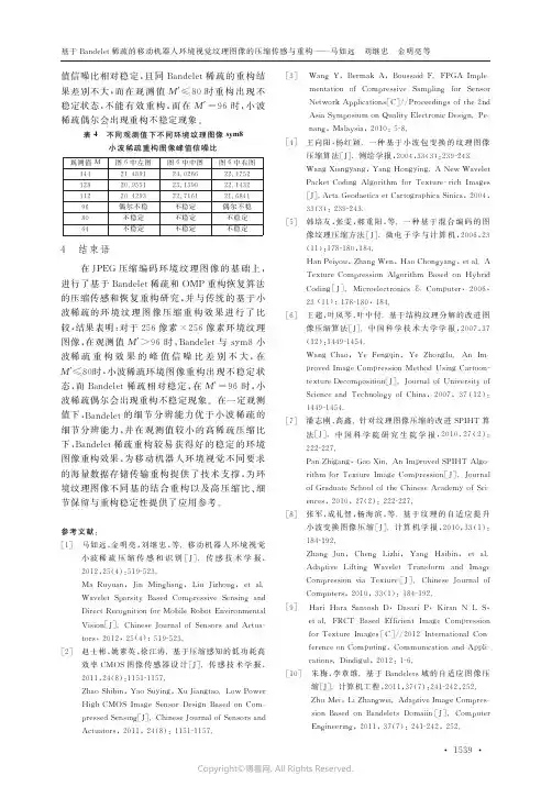
值信噪比相对稳定,且同B a n d e l e t稀疏的重构结果差别不大,而在观测值M'≤80时重构出现不稳定状态,不能有效重构,而在M'=96时,小波稀疏偶尔会出现重构不稳定现象㊂表4 不同观测值下不同环境纹理图像s y m8小波稀疏重构图像峰值信噪比观测值M图6中左图图6中中图图6中右图14421.489124.026622.475212820.955123.139022.143211220.429322.716121.684196偶尔不稳不稳定偶尔不稳80不稳定不稳定不稳定64不稳定不稳定不稳定4 结束语在J P E G压缩编码环境纹理图像的基础上,进行了基于B a n d e l e t稀疏和OM P重构恢复算法的压缩传感和恢复重构研究,并与传统的基于小波稀疏的环境纹理图像压缩重构效果进行了比较,结果表明:对于256像素×256像素环境纹理图像,在观测值M'>96时,B a n d e l e t与s y m8小波稀疏重构效果的峰值信噪比差别不大,在M'≤80时,小波稀疏环境图像重构出现不稳定状态,而B a n d e l e t稀疏相对稳定,在M'=96时,小波稀疏偶尔会出现重构不稳定现象㊂在一定观测值下,B a n d e l e t的细节分辨能力优于小波稀疏的细节分辨能力,并在观测值较小的高稀疏压缩比下,B a n d e l e t稀疏重构较易获得好的稳定的环境图像重构效果,为移动机器人环境视觉不同要求的海量数据存储传输重构提供了技术支撑,为环境纹理图像不同基的结合重构以及高压缩比㊁细节保留与重构稳定性提供了应用参考㊂参考文献:[1] 马如远,金明亮,刘继忠,等.移动机器人环境视觉小波稀疏压缩传感和识别[J].传感技术学报,2012,25(4):519‐523.M a R u y u a n,J i n M i n g l i a n g,L i u J i z h o n g,e ta l.W a v e l e tS p a r s i t y B a s e d C o m p r e s s i v e S e n s i n g a n dD i r e c tR e c o g n i t i o n f o rM o b i l eR o b o tE n v i r o n m e n t a lV i s i o n[J].C h i n e s eJ o u r n a lo fS e n s o r sa n d A c t u a-t o r s,2012,25(4):519‐523.[2] 赵士彬,姚素英,徐江涛.基于压缩感知的低功耗高效率C MO S图像传感器设计[J].传感技术学报,2011,24(8):1151‐1157.Z h a oS h i b i n,Y a oS u y i n g,X u J i a n g t a o.L o wP o w e rH i g hC MO SI m a g eS e n s o rD e s i g nB a s e do nC o m-p r e s s e dS e n s i n g[J].C h i n e s e J o u r n a l o f S e n s o r s a n dA c t u a t o r s,2011,24(8):1151‐1157.[3] W a n g Y,B e r m a k A,B o u s s a i d F.F P G AI m p l e-m e n t a t i o n o f C o m p r e s s i v e S a m p l i n g f o r S e n s o rN e t w o r kA p p l i c a t i o n s[C]//P r o c e e d i n g so f t h e2n dA s i aS y m p o s i u mo nQ u a l i t y E l e c t r o n i cD e s i g n.P e-n a n g,M a l a y s i a,2010:5‐8.[4] 王向阳,杨红颖.一种基于小波包变换的纹理图像压缩算法[J].测绘学报,2004,33(3):239‐243.W a n g X i a n g y a n g,Y a n g H o n g y i n g.A N e w W a v e l e tP a c k e tC o d i n g A l g o r i t h m f o rT e x t u r e‐r i c hI m a g e s[J].A c t aG e o d a e t i c a e tC a r t o g r a p h i c aS i n i c a,2004, 33(3):239‐243.[5] 韩培友,张雯,郝重阳,等.一种基于混合编码的图像纹理压缩方法[J].微电子学与计算机,2006,23(11):178‐180,184.H a nP e i y o u,Z h a n g W e n,H a oC h o n g y a n g,e t a l.AT e x t u r eC o m p r e s s i o n A l g o r i t h m B a s e do n H y b r i dC o d i n g[J].M i c r o e l e c t r o n i c s&C o m p u t e r,2006,23(11):178‐180,184.[6] 王超,叶凤琴,叶中付.基于结构纹理分解的改进图像压缩算法[J].中国科学技术大学学报,2007,37(12):1449‐1454.W a n g C h a o,Y e F e n g q i n,Y e Z h o n g f u.A nI m-p r o v e d I m a g eC o m p r e s s i o n M e t h o dU s i n g C a r t o o n‐t e x t u r eD e c o m p o s i t i o n[J].J o u r n a l o fU n i v e r s i t y o f S c i e n c ea n d T e c h n o l o g y o fC h i n a,2007,37(12): 1449‐1454.[7] 潘志刚,高鑫.针对纹理图像压缩的改进S P I H T算法[J].中国科学院研究生院学报,2010,27(2): 222‐227.P a nZ h i g a n g,G a oX i n.A n I m p r o v e dS P I H T A l g o-r i t h mf o rT e x t u r eI m a g eC o m p r e s s i o n[J].J o u r n a l o fG r a d u a t eS c h o o l o f t h eC h i n e s eA c a d e m y o fS c i-e n c e s,2010,27(2):222‐227.[8] 张军,成礼智,杨海滨,等.基于纹理的自适应提升小波变换图像压缩[J].计算机学报,2010,33(1): 184‐192.Z h a n g J u n,C h e n g L i z h i,Y a n g H a i b i n,e t a l.A d a p t i v e L i f t i n g W a v e l e t T r a n s f o r m a n d I m a g eC o m p r e s s i o nv i a T e x t u r e[J].C h i n e s eJ o u r n a lo fC o m p u t e r s,2010,33(1):184‐192.[9] H a r i H a r aS a n t o s h D,D a s a r iP,K i r a n N L S,e t a l.F R C T B a s e d Ef f i c i e n tI m ag e C o m p r e s s i o nf o rT e x t u r eI m ag e s[C]//2012I n t e r n a t i o n a lC o n-f e r e n c e o nC o m p u t i n g,C o mm u n i c a t i o na n d A p p l i-c a t i o n s.D i nd i g u l,2012:1‐6.[10] 朱梅,李章维.基于B a n d e l e t s域的自适应图像压缩[J].计算机工程,2011,37(7):241‐242,252.Z h u M e i,L i Z h a n g w e i.A d a p t i v e I m a g eC o m p r e s-s i o nB a s e do n B a n d e l e t s D o m a i i n[J].C o m p u t e rE n g i n e e r i n g,2011,37(7):241‐242,252.㊃9351㊃基于B a n d e l e t稀疏的移动机器人环境视觉纹理图像的压缩传感与重构 马如远 刘继忠 金明亮等Copyright©博看网. All Rights Reserved.[11] 田润澜,肖卫华,齐兴龙.几种图像变换算法性能比较[J ].吉林大学大学报:信息科学版,2010,28(5):439‐444.T i a n R u n l a n ,X i a o W e i h u a ,Q iX i n g l o n g .C o m -p a r i o no f S e v e r a l I m a geT r a n s f o r m [J ].J o u r n a l o f J i l i n U n i v e r s i t y (I n f o r m a t i o n S c i e n c e E d i t i o n ),2010,28(5):439‐444.[12] 金坚,谷源涛,梅顺良.压缩采样技术及其应用[J ].电子与信息学报,2010,32(2):470‐475.J i nJ a n ,G u Y u a n t a o ,M e iS h u n l i a n g .A nI n t r o -d u c t i o n t oC o m p r e s s i v eS a m p l i n g a n d I t sA p p l i c a -t i o n s [J ].J o u r n a lo f E l e c t r o n i c s &I n f o r m a t i o n T e c h n o l o g y,2010,32(2):470‐475.[13] I q b a lM ,C h e nJ .C o m p r e s s i v eS a m p l i n g o fN a t u -r a l I m a g e sU s i n g B a n d e l e t B a s i s [C ]//20114t h I n -t e r n a t i o n a lC o n f e r e n c eo nI m a g ea n d S i g n a lP r o -c e s s i n g .S h a n gh a i ,2011:958‐962.[14] D o n o h oDL ,H u oX M.U n c e r t a i n t y P r i n c i pl e s a n d I d e a lA t o m i c D e c o m p o s i t i o n [J ].I E E E T r a n s a c -t i o n so nI n f o r m a t i o n T h e o r y,2001,47:2845‐2862.[15] D o n o h oDL ,T s a i g Y.E x t e n s i o n so fC o m pr e s s e d S e n s i n g [J ].S i g n a lP r o c e s s i n g,2006,47:549‐571.(编辑 袁兴玲)作者简介:马如远,女,1973年生㊂浙江工业大学机械工程学院博士研究生,嘉兴学院数理与信息工程学院讲师㊂主要研究方向为机器人视觉与模式识别㊂刘继忠(通信作者),男,1974年生㊂南昌大学机器人研究所副教授㊁博士㊂金明亮,男,1988年生㊂南昌大学机器人研究所硕士研究生㊂柴国钟,男,1957年生㊂浙江工业大学机械工程学院教授㊂王光辉,男,1968年生㊂南昌大学机器人研究所教授㊂负泊松比蜂窝芯非线性等效弹性模量研究鲁 超 李永新 吴金玺 刘 明 李天齐中国科学技术大学,合肥,230027摘要:设计并加工了一种负泊松比蜂窝结构,采用柔性悬臂梁模型,对蜂窝壁板大变形条件下的弯曲变形进行分析,给出了蜂窝芯面内等效弹性模量理论计算公式㊂通过有限元仿真和力学实验的对比分析,验证了非线性理论计算公式的正确性㊂得出了等效弹性模量的非线性特性及相同方向和不同方向弹性模量的变化特性㊂研究结果为柔性蜂窝芯层的工程实用化提供了参考㊂关键词:蜂窝芯;负泊松比;非线性;等效弹性模量中图分类号:T B 383 D O I :10.3969/j.i s s n .1004-132X.2014.11.022R e s e a r c ho nN o n ‐l i n e a rE q u i v a l e n tE l a s t i cM o d u l u s o fN e ga t i v e P o i s s o n ’sR a t i oH o n e y c o m bC o r e ‐l a ye r L uC h a o L iY o n g x i n W u J i n x i L i u M i n g L iT i a n qi U n i v e r s i t y o f S c i e n c e a n dT e c h n o l o g y ofC h i n a ,H e f e i ,230027A b s t r a c t :An e g a t i v eP o i s s o n ’s r a t i oh o n e y c o m bs t r u c t u r ew a sd e s i gn e da n d f a b r i c a t e dh e r e i n ,a f l e x i b l e c a n t i l e v e rm o d e lw a su s e d t oa n a l y z e t h eb e n d i n g d e f o r m a t i o no f t h eh o n e yc o m b p a n e l u nde r t h e s i t u a t i o nof l a rg e d e f o r m a t i o n ,th e nd e d u c e d a t h e o r e ti c a l f o r m u l au s e d t o c a l c u l a t e t h e e qu i v a l e n t e l a s t i cm o d u l u s .T h r o u g ht h ee x p e r i m e n t a l c o m pa r i s o no f f i n i t ee l e m e n ts i m u l a t i o na n d m e c h a n i c a l a n a l y s i s ,t h e p a p e r v e r i f i e d t h e c o r r e c t n e s s o f t h e n o n ‐l i n e a r t h e o r y f o r m u l a ,ob t a i n e dn o n l i n e a rc h a r -a c t e r i s t i c so f t h e e q u i v a l e n t e l a s t i cm o d u l u s a n d t h e v a r i a t i o n c h a r a c t e r i s t i c o f t h em o d u l u s o f e l a s t i c i t y o f t h e s a m e d i r e c t i o n a n d i n d i f f e r e n t d i r e c t i o n s .I t p r o v i d e s r e f e r e n c e f o r f l e x ib l e h o n e yc o m b c o r e ‐l a y e r s t r u c t u r e o f t h e e n g i n e e r i n gpr a c t i c e s .K e y wo r d s :h o n e y c o m bc o r e ‐l a y e r ;n e g a t i v eP o i s s o n ’sr a t i o ;n o n ‐l i n e a r i t y ;e q u i v a l e n te l a s t i c m o d u l u s0 引言如何设计既能大幅度连续光滑变形,又有足收稿日期:2013 01 10基金项目:国家自然科学基金资助项目(51075380);国家自然科学基金资助重点项目(90816026)够刚度和强度的轻质可变形蒙皮[1‐2]结构已成为智能变形飞行器的关键技术之一[3‐5]㊂目前,对于弹性蒙皮[1]的研究主要集中在以下两个方面:一种是波纹板式复合材料弹性蒙皮[5],该蒙皮利用波纹扩张或收缩产生的变形累积效应实现沿波纹方向的大变形,但是该蒙皮表面并不连续平滑,同㊃0451㊃中国机械工程第25卷第11期2014年6月上半月Copyright ©博看网. All Rights Reserved.时垂直于波纹方向的纵向承载能力很弱;另一种是采用柔性较大的橡胶类材料制作的蒙皮,这种蒙皮虽能满足机翼变形和气密性的要求,但驱动方式和变形控制很复杂,而且机翼的整体承载能力不高[6]㊂本文提出了基于柔性蜂窝结构的超弹性蒙皮结构设计理念,以期得到变形柔度㊁承载刚度㊁轻质三方面性能俱佳的可变形蒙皮结构㊂蜂窝芯柔性大变形问题的研究是柔性蜂窝芯超弹性蒙皮研制的基础㊂在单一规则蜂窝结构的研究中,宏观上将其视为匀质连续材料,选取其中的一个单元进行宏观结构上的等效力学和变形分析,进而得到结构的等效弹性模量㊂G i b s o n等[7]运用E u l e r梁模型,对蜂窝结构的力学行为进行分析研究,得出了蜂窝结构弹性模量的经典计算公式(G i b s o n公式)㊂富明慧等[8]在考虑蜂窝壁板伸缩变形的情况下,对G i b s o n公式进行了修正㊂W a r-r e n等[9]依据蜂窝结构中单元周期性重复排列的特点,取其代表单元进行分析,建立了宏观的弹性本构方程,得出了W‐K公式㊂王飞等[10]根据均匀化理论,并结合有限元方法得出了不同相对密度下蜂窝结构的等效弹性参数㊂以上研究多以小变形性为前提假设,但小变形性难以满足超弹性蒙皮的大变形要求[7,11]㊂柯映林等[12]将蜂窝壁板的变形归属于薄板大挠度变形问题,得出了具有非线性响应的蜂窝芯材料等效面内弹性模量㊂H u等[13]通过分析蜂窝壁板的扭转变形,发现弹性模量随应变的变化已经不再是常数㊂祝涛等[14]考虑蜂窝壁板面内荷重对壁板弯曲的影响,对G i b s o n公式进行了修正,提出了一种蜂窝芯层的非线性等效拉伸弹性模量的拟合方法㊂目前,对蜂窝结构非线性大变形问题的研究尚无成熟的理论体系形成,实验研究则更为有限㊂本文设计并加工了内六角形负泊松比蜂窝结构,通过理论建模㊁有限元仿真和力学实验3种方式对这种蜂窝结构大变形下的面内弹性模量进行了分析,建立了弹性模量的理论计算公式,得出了等效弹性模量的非线性特性及相同方向和不同方向弹性模量的变化特性㊂1 蜂窝结构变形力学建模1.1 Y方向单向压缩变形图1为超弹性柔性蜂窝芯蒙皮结构原理示意图和蜂窝单元图㊂其中,a为横壁板长,b为斜壁板长,t为斜壁板厚度,w为横壁板厚度,θ为斜壁板与横壁板的夹角㊂假设横壁板为刚性(w≥2t),蜂窝结构的变(a)超弹性柔性蜂窝芯蒙皮结构原理示意图(b)蜂窝单元图图1 超弹性柔性蜂窝芯蒙皮结构原理示意图和蜂窝单元图形由斜壁板的弹性变形引起㊂选取斜壁板O C B 为研究对象,将其视为一端固支(O点),一端限制其转角(B点)的细长杆(t/b≤0.015),其受力变形图见图2a㊂由于整个壁板的受力变形成反对称性,故取其一半建立柔性悬臂梁模型进行分析(图2b)㊂图2b中γ为任意截面的转角,s*为斜壁板变形后的弧长,α为载荷P(与Y轴平行)与X*轴的夹角㊂(a)斜壁板受力变形图(b)半壁板受力变形图图2 斜壁板受Y方向单向压力变形图悬臂梁的挠曲线方程为E s I d2γd s*2=-P s i n(α+γ)(1)式中,E s为材料本身的弹性模量;I为斜壁板的惯性矩㊂引入ξ=P/P c r,s=s*/b(P c r=π2E s I/b2, 0≤s≤0.5),并代入边界条件(C点的弯矩为零)可得dγd s=2πξs i n2(α2+γ12)-s i n2(α2+γ2)(2)令s i nη=s i n(α/2+γ/2)s i n(α/2+γ1/2),γ1为壁板的最大转角(即C点处的转角),则d s=dγ2πξs i n(α/2+γ1/2)c o sη=dηπξc o s(α/2+γ/2)(3)对s进行积分和坐标转换,可得其在X㊁Y方向上的投影为XéëêêùûúúY=4ξπp c o s m[E(p)-E(m,p)]-12[F(p)-F(m,péëêêêùûúúú)](4)㊃1451㊃负泊松比蜂窝芯非线性等效弹性模量研究 鲁 超 李永新 吴金玺等Copyright©博看网. All Rights Reserved.p =si n α+γ12m =a r c s i n s i n (α/2)s i n (α/2+γ1/2[])F (m ,p )=∫m011-p 2s i n 2ηd ηF (p )=∫π/211-p 2s i n 2ηd ηE (m ,p )=∫m01-p 2s i n 2ηd ηE (p )=∫π/21-p 2si n 2ηd η1.2 Y 方向单向拉伸变形Y 方向单向拉伸时,斜壁板受力变形如图3所示㊂(a)斜壁板受力变形图(b)半壁板受力变形图图3 斜壁板受Y 方向单向拉力变形图悬臂梁的挠曲线方程为E s I d 2γd s*2=-P s i n (α-γ)(5)采用上一节同样的方法进行推导可得量纲一杆长s 在X ㊁Y 方向上的投影为X éëêêùûúúY =4ξπp c o s m 12[F (p )-F (m ,p )]-[E (p )-E (m ,p éëêêêùûúúú)](6)p =co s α-γ12m =π-a r c s i nc o s (α/2)c o s (α/2-γ1/2[])对于斜壁板X 方向的受力变形情况,可依照斜壁板Y 方向受力分析的方法进行分析㊂2 蜂窝芯等效弹性模量利用上节的结论,可求得相应大变形的格林应变,进而求得等效弹性模量㊂分别用上标1㊁2表示蜂窝材料单向压缩和拉伸的受力状态,下标x ㊁y 表示受力方向分别为X ㊁Y 向,则等效弹性模量公式为E (1)xE (2)x E (1)y E (2)éëêêêêêùûúúúúúy=π2ξ2E s 12(t b )3㊃1s i n θ[X (1)x -c o s θa /b -c o s θ+12(X (1)x -c o s θa /b -c o s θ)2]1s i n θ[X (2)x -c o s θa/b -c o s θ+12(X (2)x -c o s θa /b -c o s θ)2]1(a /b -c o s θ)[Y (1)y -s i n θs i n θ+12(Y (1)y -s i n θs i n θ)2]1(a /b -c o s θ)[Y (2)y -s i n θs i n θ+12(Y (2)y -s i n θs i n θ)2éëêêêêêêêêêêêêêêùûúúúúúúúúúúúúúú](7)3 理论计算㊁A N S Y S 仿真㊁模型实验结果分析采用65M n 弹簧钢加工出单个单元实验模型,在弹性变形范围内进行了X 方向和Y 方向的拉伸㊁压缩实验,模型受力变形如图4所示㊂通过测量载荷力和位移计算出应力和应变,进而求得等效弹性模量㊂选择满足超弹性大挠度和大应变能力的S o i l d 187单元对蜂窝结构进行有限元仿真分析㊂根据实验模型的材料㊁尺寸参数和载荷,设定有限元模型的材料㊁尺寸参数和载荷量级,通过数值模拟计算出应变,进而求得等效弹性模量㊂模型的参数为:E s =196.2G P a ㊁a =55mm ㊁b =43mm ㊁t =0.4mm ㊁h =18.5mm (蜂窝芯层的厚度)㊁θ=70°㊂并将理论计算(式(7)计算结果)㊁A N S Y S 有限元仿真㊁模型实验㊁线性计算的结果[7,15]进行比较分析,给出应力应变㊁等效弹性模量应变关系,如图5~图8所示㊂线性计算公式为E x =E s (t b )3(a /b -c o sθ)s i n 3θE y =E s (t b )3s i n 2θc o s θ(c o s θ-a /b üþýïïïï)(8) (a )X 方向单向拉伸(b )Y 方向单向压缩图4 模型实验受力变形图由图5~图8可得如下结论:①图5~图8表明,理论㊁仿真㊁实验三条曲线吻合程度良好,证明了等效弹性模量计算公式的正确性和有效性;②从图5㊁图6可以看出,Y 方向的等效弹性模量非㊃2451㊃中国机械工程第25卷第11期2014年6月上半月Copyright ©博看网. All Rights Reserved.(a )应力应变关系图(b)等效弹性模量应变关系图图5 Y 方向单向压缩加载应力应变和等效弹性模量应变图(a )应力应变关系图(b)等效弹性模量应变关系图图6 Y 方向单向拉伸加载应力应变和等效弹性模量应变图线性特征明显㊂单向压缩㊁拉伸应变趋于零时等效弹性模量趋于线性计算的固定值;③从图7㊁图8可以看出,X 方向等效弹性模量近似于线性变化,应变趋于零时等效弹性模量趋于线性计算的(a)应力应变关系图(b)等效弹性模量应变关系图图7 X 方向单向压缩加载应力应变和等效弹性模量应变图(a)应力应变关系图(b)等效弹性模量应变关系图图8 X 方向单向拉伸加载应力应变和等效弹性模量应变图固定值,随应变的增大等效弹性模量和线性计算值的差值增大,因此,大变形条件下柔性蜂窝芯X 方向等效弹性模量的计算应选用更为精确的非线性计算公式;④图5~图8表明,同一方向单向拉㊃3451㊃负泊松比蜂窝芯非线性等效弹性模量研究鲁 超 李永新 吴金玺等Copyright ©博看网. All Rights Reserved.。
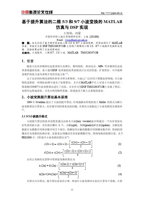
基于提升算法的二维5/3和9/7小波变换的MATLAB仿真与DSP 实现王靖琰,刘蒙中国科学院上海应用物理研究所,上海 (201800)E-mail :wjycas@摘 要:本文讨论了基于提升算法的二维5/3和9/7小波的原理,对算法进行了MATLAB 仿真,并在浮点型DSP TMS320C6713B 上实现了图像的二维5/3、9/7小波提升变换和逆变换。
实验结果证明了方法的有效性。
关键词:小波提升,二维9/7、5/3小波,MATLAB ,TMS320C6713B1.引言随着人们对多媒体信息需求的日益增长,数码相机、移动电话、MP4 等多媒体信息处理系统蓬勃发展。
基于通用DSP 处理器的此类系统设计以灵活性强、扩展性好、可升级和易维护的优点成为系统开发的首选方案 [1]。
由于良好的时频局部特性和多分辨分析特性,小波已广泛应用于图像处理领域,并且被吸收进新的一些国际标准中成为了标准算法。
文中在MATLAB 平台上对基于小波提升的二维离散5/3和9/7小波变换算法进行了仿真,并在浮点型DSP TMS320C6713B 上实现了算法,该程序运算速度快,可充分利用硬件资源,特别适用于嵌入式系统的需求。
2.小波变换提升算法基本原理1994年Sweldens 提出了小波的提升算法,有效地解决传统的基于Mallat 的塔式分解小波变换算法计算量大、对存储空间的要求高的问题,从算法方面提高了小波变换的实现效率[2]。
2.1 5/3小波提升格式小波提升算法的基本思想是通过由基本小波(lazy wavelet)逐步构建出一个具有更加良好性质的新小波,其实现步骤有3个:分解(split)、预测(predict)和更新(update)。
分解是将数据分为偶数序列和奇数序列2个部分,预测是用分解的偶数序列预测奇数序列,得到的预测误差为变换的高频分量,更新是由预测误差来更新偶数序列,得到变换的低频分量。
在J PEG2000中,5/3提升小波变换的算法为[3]:(2)(22)(21)(21)(1)2(21)(21)2(2)(2)(2)4x n x n c n x n c n c n d n x n ++⎡⎤+=+−⎢⎥⎣⎦−+++⎡⎤=+⎢⎥⎣⎦由其正变换的反置即可得到逆变换的算法为 c(2n-1) + c(2n+1)+2x (2n) = d (2n) - (3)4x(2n)+x(2n+2)x(2n+1)=c(2n)+(4)2⎡⎤⎢⎥⎣⎦⎡⎤⎢⎥⎣⎦ 从算式可以得出,提升算法是原位计算,即进行小波变换时在原位计算各个系数,计算的系数可以直接替代原始数据而不需要附加数据存储空间。
专利名称:Wavelet based feature extraction anddimension reduction for the classification ofhuman cardiac electrogram depolarizationwaveforms发明人:Christopher S. de Voir申请号:US11933924申请日:20071101公开号:US07751873B2公开日:20100706专利内容由知识产权出版社提供专利附图:摘要:A depolarization waveform classifier based on the Modified lifting line waveletTransform is described. Overcomes problems in existing rate-based event classifiers. A task for pacemaker/defibrillators is the accurate identification of rhythm categories so correct electrotherapy can be administered. Because some rhythms cause rapid dangerous drop in cardiac output, it's desirable to categorize depolarization waveforms on a beat-to-beat basis to accomplish rhythm classification as rapidly as possible. Although rate based methods of event categorization have served well in implanted devices, these methods suffer in sensitivity and specificity when atrial/ventricular rates are similar. Human experts differentiate rhythms by morphological features of strip chart electrocardiograms. The wavelet transform approximates human expert analysis function because it correlates distinct morphological features at multiple scales. The accuracy of implanted rhythm determination can then be improved by using human-appreciable time domain features enhanced by time scale decomposition of depolarization waveforms.申请人:Christopher S. de Voir地址:Tigard OR US国籍:US代理机构:ARC IP Law, PC代理人:Joseph J. Mayo更多信息请下载全文后查看。
第31卷第1期2021年3月洛阳理工学院学报(自然科学版)Journal of Luoyang Institute of Science and Technology(Natural Science Edition)Vol.31No.1Mar.2021基于LWT-SVD-DCT算法的水印技术李伟1,孙云娟2(1.河南师范大学电子与电气工程学院,河南新乡453007;2.河南师范大学新联学院,河南新乡453007)摘要:基于提升小波变换(LWT)、奇异值分解(SVD)和离散余弦变换(DCT),提出一种新的盲水印技术方案。
首先,将原始图像进行LWT变换,提取LL子带;然后,将子带划分成互不相交的模块进行SVD分解;最后,将正交向量色进行一维DCT变换得到毎,再把二进制水印的每一位嵌入到逐的中频系数中。
仿真实验表明:该算法运算速度快,重构图像精确,具有鲁棒性和透明性。
关键词:盲水印技术;提升小波变换;奇异值分解;离散余弦变换D0I:10.3969/j.issn.1674—5043.2021.01.015中图分类号:TP317.4文献标识码:A文章编号:1674-5043(2021)01-0077-05因特网改变了人们的生活方式,在因特网上人们可以交互多媒体文本和数据,女口:语音、数据和图像等。
然而,一个必须面对的突出问题是版权保护,即抑制非法复制和传播。
近些年,数字图像水印技术已经应用于多媒体文本和数据的版权保护。
Vivekananda等[1]提出了一个具有鲁棒性和透明性的有效水印技术,该技术在DWT域中进行奇异值分解(SVD),缺点是容易产生误判;Run等[2]提出了一种改进算法,在DWT域中嵌入主值分量;为了进一步提高鲁棒性和透明性,有人引入优化算法计算嵌入水印强度系数[3-5],有人提出LWT算法水印技术[6-8]。
本文提出了基于提升小波理论的LWT-SVD-DCT水印技术,提升小波变换计算效率高,在整数域图像重构精确,SVD技术是一个强有力的工具用于图像压缩和数据隐藏,DCT变换对于高相关性图像数据具有好的能量堆栈特性。
旋转机械轴承振动信号分析方法研究重庆大学博士学位论文学生姓名:彭*指导教师:柏林教授专业:机械电子工程学科门类:工学重庆大学机械工程学院二O一四年三月Vibration signal analysis of bearings in therotating machineryA Thesis Submitted to Chongqing Universityin Partial Fulfillment of the Requirement for theDoctor‟s Degree of EngineeringByPeng ChangSupervised by Prof. Bo LinSpecialty:Mechatronics EngineeringCollege of Mechanical Engineering of Chongqing University,Chongqing, ChinaMarch 2014中文摘要摘要轴承作为旋转机械中广泛使用的关键零部件之一,其运行状态直接关系整台机械设备的工作性能,开展基于振动信号分析的轴承状态监测与故障诊断的相关研究并及时准确地识别故障萌发与演变,对确保设备平稳运行、减少甚至避免重大安全事故具有相当重要的意义。
本课题以滚动轴承及滑动轴承故障振动信号为研究对象,针对滚动轴承故障信号易受噪声干扰的影响拓展并丰富了峭度图理论在振动信号降噪以及故障特征提取中的应用,并基于定向循环平稳分析理论研究了滑动轴承在油膜失稳状态下的故障信号特征,最后开发了虚拟式旋转机械轴承测试诊断系统实现了理论创新成果在工程实践中的应用。
本文的具体研究内容介绍如下:本文首先介绍了峭度图理论中涉及的峭度统计理论、谱峭度系数等数学基础,并详细阐述了传统峭度图算法以及基于COT的阶比峭度图算法在故障信号降噪和最优解调频带参数确定方面的优势。
针对传统四阶矩累积量谱峭度系数易受信号奇异点影响而不能真实估计信号峰态程度水平的问题,定义了Moors谱峭度、Hogg 谱峭度以及Crow-Siddiqui谱峭度等三种鲁棒性谱峭度系数,并提出了能消除信号奇异点干扰的鲁棒性峭度图算法。
基于激光雷达资料的小波变换法反演边界层高度的方法李红;马媛媛;杨毅【期刊名称】《干旱气象》【年(卷),期】2015(000)001【摘要】When applying wavelet transformation method in the retrieval of the boundary layer height by using lidar backscatter signals, the different selection of wavelet generating function may get different results. Therefore,the idealized lidar signal profiles during the daytime and nighttime have been built to explore which wavelet generating function will get the best performance. In this study,Haar wavelet covariance transformation has been used for the profiles of lidar backscatter signal,and Morlet and Mexican Hat wavelet trans-formation have been utilized for the gradient profiles of lidar backscatter signal,respectively. The results showed that the Haar function and the Mexican Hat function should be used as wavelet generating functions:the Haar function is more accurate and the Mexican Hat function is more stable. Furthermore,the changed wavelet dilation of the wavelet generating function also has been researched in order to test the sensitivity of the three different wavelet transformation methods to the wavelet dilation. The result show that whatever the ide-alized profile or the profile in which disturbance was added,the larger wavelet dilation can get a more stable and accurate diurnal boundary layer height and nocturnal mixing layer height.%利用小波变换法反演边界层高度时,不同小波母函数的选取可能得到不同的边界层高度。
星上大视场TDICCD相机的多光谱图像无损压缩系统李进;金龙旭;李国宁;韩双丽;张然峰【摘要】提出了一种适于成像谱段数相对较少的多光谱TDICCD图像的无损压缩系统.所提出的压缩系统主要分为两步:第一步采用SPE架构的5/3提升整数小波变换去除空间冗余;第二步根据小波系数统计依赖性模型对小波系数进行预测,来消除残余空间冗余和小波系数的谱段冗余.然后将其与预测值做差进而得到预测残差,同时将预测残差进行熵编码得到最终的压缩码流.最后,使用地检检测设备对多光谱TDICCD图像无损压缩系统进行了试验验证.结果表明,压缩系统能快速、可靠稳定地工作,无损压缩比达到1.544 bits/pixel,比现有压缩系统压缩比提高了0.336 bits/pixel.相机工作在不同的侧摆下,压缩系统可以稳定正常地工作,压缩一帧图像最大耗时仅为26.446 ms.本文所提出的压缩系统有效地解决了多光谱TDICCD图像无损压缩比低和压缩算法整体硬件实现困难的问题.【期刊名称】《发光学报》【年(卷),期】2013(034)004【总页数】10页(P506-515)【关键词】多光谱空间相机;无损压缩;SPE单元;小波系数依赖性;小波系数预测【作者】李进;金龙旭;李国宁;韩双丽;张然峰【作者单位】中国科学院长春光学精密机械与物理研究所,吉林长春130033;中国科学院大学,北京100049;中国科学院长春光学精密机械与物理研究所,吉林长春130033;中国科学院长春光学精密机械与物理研究所,吉林长春130033;中国科学院长春光学精密机械与物理研究所,吉林长春130033;中国科学院长春光学精密机械与物理研究所,吉林长春130033【正文语种】中文【中图分类】TP391.41 引言目前,基于光谱谱段数相对较少的多光谱TDICCD成像技术的空间相机对视场和空间分辨率指标要求的不断提高,使得所采用的CCD拼接片数和读出速率也不断增多和提高,从而使数字化后的CCD图像数据量呈指数增加[1-3],给卫星图像存储和传输带来了巨大的挑战。
A folded multiplierless,lifting based wavelet pipelineM.Martina,G.MaseraAbstractA folded,multiplierless lifting based wavelet pipeline for the9/7and the5/3filters is presented.The proposedpipeline requires a small amount of logic and achieves a100%hardware utilization with a performance loss lower than0.7dB compared to a JPEG2000compliant wavelet stage.I.I NTRODUCTIONThe lifting scheme(LS)based wavelet transform[1]is the decorrelation stage employed in JPEG2000[2],where the9/7and the5/3waveletfilters are used for lossy and lossless compression respectively.It is known that the5/3 waveletfilters can be implemented with a simple multiplierless two steps LS,whereas the9/7waveletfilters require non rational multiplications with four lifting steps and a scaling factorζ.In Fig.1(a)the standard LS for the9/7 waveletfilters is shown where the four lifting coefficientsα,β,γ,δand the scaling factorζare evidenced.Besides in Table I thefirst column summarizes the9/7lifting coefficients values whereas in the third column the5/3lifting coefficients values are given.As a consequence multipliers are required to calculate the9/7wavelet transform. Moreover,since the number of lifting steps is different for the9/7and the5/3waveletfilters,the number of clock cycles required to produce the results is different.In[3]the rational9/7lifting factorization proposed in[4]is combined with theflipping structure[5]to achieve a multiplierless architecture(see Fig.1(b)and Table I second column).The main drawback of the multiplierless lifting-flipping(LF)architecture described in[3]is the scaling factor(ζ=4/5in the normalized form)that ought to be embedded into the successive stage(e.g.the quantizer).In order to embody the5/3computation into the LF architecture some bypass multiplexers are required,leading to a 100%hardware use for the9/7computation and to near50%hardware use for the5/3.In this paper we show that the two lifting steps wavelet derived in[6]achieves near JPEG20009/7performance with a significant complexity reduction.Moreover a multiplierless pipeline that embodies both the9/7and the5/3wavelet transform with100% hardware utilization is shown.II.P ROPOSED ARCHITECTUREAs detailed in[6]the9/7wavelet is a symmetric biorthogonal perfect reconstructionfilter bank.The lifting factorization shown in thefirst column of Table I can be derived by applying the Euclidean algorithm[1]to the analysis low passfilter H(z)=h0+h1(z+z−1)+h2(z2+z−2)+h3(z3+z−3)+h4(z4+z−4).When h3=0a different9/7symmetric biorthogonal perfect reconstruction wavelet is obtained,whereˆH(z)is the analysis low passfilter[6].If we apply the Euclidean algorithm toˆH(z)polyphase representation we obtain only two liftingstepsˆs(z)=116(z+z−2)−916(1+z−1)andˆt(z)=14(z+1)with scaling factorˆζ=1.Let’s defineˆH(z)lifting coefficients:ˆα0=−916,ˆα1=116andˆβ=14so thatˆs(z)=ˆα0(1+z−1)+ˆα1(z+z−2)andˆt(z)=ˆβ(z+1).As it can be observed this factorization allows to share the second lifting step and the scaling factor with the5/3LS(ˆβ≡β(5,3)andˆζ≡ζ(5,3)).Thefirst5/3lifting step can be easily embedded into thefirstˆH(z)lifting step implementingˆα0=−916=−12−116=α(5,3)−116.The simple pipeline shown in Fig.2(a)folds the5/3LS intoˆH(z)LS.Some multiplexers have been added to correctly manage boundary extension when the input pixel is thefirst(P isfirst,U isfirst)or the last(P is last). The S9753n multiplexer allows to select the9/7or the5/3wavelet in thefirst lifting step(predict).III.R ESULTSTo compare the proposed pipeline to the LF solution proposed in[3]we folded the5/3lifting steps into the 9/7LF architecture.As depicted in Fig.2(b)folding the two wavelets requires to implementα(9,7)=−32=−1−12=−1+α(5,3)and seven multiplexers,which select the proper branch(e.g.β(9,7)orβ(5,3))or bypass not common parts(e.g.the third and the fourth9/7lifting steps-Predict2,Update3).For a16bits data-width VHDL implementation of the two solutions,the logical synthesis on a0.13µm standard cells technology shows that the proposed folded pipeline requires near half area(2.4kgates)compared to[3]with folded5/3lifting computation(4.5 kgates)for a200MHz target clock frequency.In order to have a complete,fair comparison we tested the two steps 9/7solution and the four steps LF scheme into openjpeg[7],a Class-1Profile-1JPEG2000codec.Experimental results summarized in Table II show the Peak Signal to Noise Ratio(PSNR)obtained for5standard512×512 images(“lena”-img1,“barbara”-img2,“boat”-img3,“goldhill”-img4,“fingerprint”-img5)at different bitrates (0.25,0.5and1bit per pixel-bpp)varying the number of wavelet decomposition levels(L∈{1,2,3,4}1)with default encoder values for precinct and code-block size.To set up the experiments we implemented into the openjpeg model the two lifting steps and the four lifting steps multiplierless solutions both at the encoder and the decoder side[8].Compared to the original openjpeg results,the four lifting steps multiplierless implementation shows a performance loss lower than0.15dB,whereas the two steps solution,detailed in Section II,grants a performance loss lower than0.7dB.R EFERENCES[1]I.Daubechies and W.Sweldens,“Factoring wavelet transforms into lifting steps,”J.Fourier Anal.Appl.,vol.4,no.3,pp.247–269,1998.[2]M.Boliek,“JPEG2000Final Committee Draft,”2000.[3]K.A.Kotteri,S.Barua,A.E.Bell,and J.E.Carletta,“A comparison of hardware implementations of the biorthogonal9/7DWT:convolutionversus lifting,”IEEE Trans.on Circuits and Systems II,vol.52,no.5,pp.256–260,May2005.[4] D.Tay,“A class of lifting based integer wavelet transform,”in IEEE International Conference on Image Processing,2001,pp.602–605. 1This corresponds toΛ∈{2,3,4,5}wavelet resolution levels[5] C.T.Huang,P.C.Tseng,and L.G.Chen,“Flipping Structure:an efficient VLSI architecture for lifting-based discrete wavelet transform,”IEEE Trans.on Signal Processing,vol.52,no.4,pp.1080–1089,Apr.2004.[6]L.Cheng,D.L.Liang,and Z.H.Zhang,“Popular biorthogonal waveletfilters via a lifting scheme and its application in image compression,”IEE Proc.on Vision,Image and Signal Processing,vol.150,no.4,pp.227–232,Aug.2003.[7]“.”[8]M.Martina,“Low Complexity9/7Wavelet:Modified OpenJPEG model,”downloadable at www.vlsilab.polito.it/∼martina.A UTHORS’AFFILIATIONSM.Martina and G.Masera(Dipartimento di Elettronica,Politecnico di Torino,Corso Duca degli Abruzzi24, I-10129Torino,Italy),maurizio.martina@polito.itFig.1.9/7LS,multiplierless LF scheme proposed in[3].Fig.2.Proposed folded pipeline(a)and[3]multiplierless LF pipeline with folded5/3lifting steps(b). Table I.Lifting coefficients:original9/7,rational9/7[4]and5/3.Table II.Performance analysis:PSNR values for different images at different bitrates(1,0.5,0.25bpp)with different wavelet decomposition levels L∈[1,4]-original openjpeg,openjpeg+[3],openjpeg+Proposed.5−1(a)(b)z lhx 22β(1+z)(1+z)δy y 1/ζζ−1lhx −122β(1+z)1/γγδ(1+z)y y γ/ζζz (1+z )α−1α(1+z )−1γ(1+z )1+z −1Fig.1.(a)(b) Fig.2.original9/7rational9/7[4]5/3α-1.58613434205992-3/2-1/2β-0.05298011857296-1/161/4γ0.882911075530934/50δ0.4435068520439715/320ζ0.812893066115964/51Image L Openjpeg[dB][3][dB]Proposed[dB] 10.50.2510.50.2510.50.25img1138.8934.2530.0038.8634.1029.9438.8134.4830.08 239.9236.7233.1939.9236.6733.1739.8536.6533.09 340.0837.2034.0640.1137.1934.0440.0137.0033.72 440.1237.2434.1340.1137.2334.1040.0136.9833.82img2135.7729.4824.0535.8229.5224.1735.5829.1623.84 237.5632.1627.6937.6032.1627.8637.4431.7827.26 337.8732.7828.7537.8732.8128.7437.5632.2528.08 437.8932.7828.8337.8632.8628.8337.5632.1928.14img3137.6632.6228.2237.5632.5328.2337.9432.7628.11 238.8733.9630.1438.8533.9030.0738.8634.0930.34 339.0434.4630.8839.0634.4530.8938.9434.3030.72 439.0834.5530.9939.0834.5330.9838.9934.3230.74img4135.7731.6827.5535.7231.7227.5135.8231.8127.40 236.3232.8730.1136.3332.9030.1436.1832.8730.12 336.4533.1530.5336.4533.1730.4936.2232.9530.31 436.4533.1930.5236.4633.2030.5036.2132.9330.28img5135.8031.7327.7635.7831.7127.8935.9231.9427.71 236.1832.3629.1436.1532.3229.0736.0932.2329.26 336.2632.4529.4836.2332.4129.4236.0932.2029.29 436.2532.4829.5236.2332.4429.4736.0832.1929.21.。