H3C不同VLAN之间的通讯配置实例
- 格式:docx
- 大小:81.81 KB
- 文档页数:3

H3C交换机vlan配置实例H3C交换机vlan配置实例H3C能够提供业界覆盖最全面的交换机产品。
从园区到数据中心、盒式到箱式、从FE、GE到10G和100G,从L2到L4/7,从IPv4到IPv6,从接入到核心,用户都有最丰富的`选择和灵活的组合。
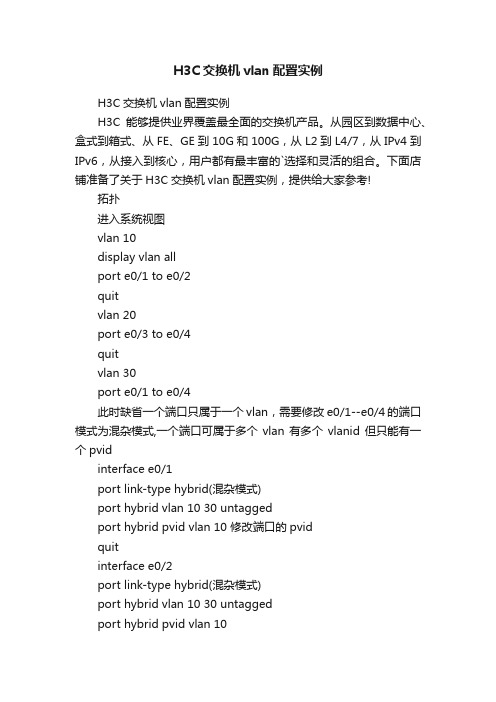
下面店铺准备了关于H3C交换机vlan配置实例,提供给大家参考!拓扑进入系统视图vlan 10display vlan allport e0/1 to e0/2quitvlan 20port e0/3 to e0/4quitvlan 30port e0/1 to e0/4此时缺省一个端口只属于一个vlan,需要修改e0/1--e0/4的端口模式为混杂模式,一个端口可属于多个vlan有多个vlanid 但只能有一个pvidinterface e0/1port link-type hybrid(混杂模式)port hybrid vlan 10 30 untaggedport hybrid pvid vlan 10 修改端口的pvidquitinterface e0/2port link-type hybrid(混杂模式)port hybrid vlan 10 30 untaggedport hybrid pvid vlan 10quitinterface e0/3port link-type hybrid(混杂模式)port hybrid vlan 20 30 untaggedport hybrid pvid vlan 20quitinterface e0/4port link-type hybrid(混杂模式)port hybrid vlan 20 30 untaggedport hybrid pvid vlan 20quitinterface e0/9port link-type hybrid(混杂模式)port hybrid vlan 10 20 30 untaggedport hybrid pvid vlan 30quit;vlan 10 1 2 9;vlan 20 3 4 9;vlan 30 1 2 3 4 9 vlanid配置完成,此时需要确定pvid 是否正确display interface e 0/1 ; 查看端口信息中的缺省pvid项端口untagged 的目的是如果9口接不支持标记的设备如单台服务器的网卡,则不通信,如果9口接上级交换则也可tagged。
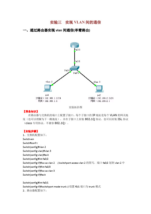
实验三实现VLAN间的通信一、通过路由器实现vlan间通信(单臂路由)实验拓扑图【准备知识】在路由器与交换机的端口上配置子接口,每个子接口的IP地址是每个VLAN的网关地址(也可以理解为下一跳地址),并在子接口上封装802.1Q协议。
也可以封装ISL协议(cisco专用协议,不兼容802.1Q)。
【实验步骤】1、交换机配置如下:Switch>enSwitch#conf tSwitch(config)#vlan 2Switch(config-vlan)#vlan 3Switch(config-vlan)#exitSwitch(config)#int fa0/2Switch(config-if)#sw ac vlan 2 //switchport access vlan 2的简写,端口fa0/2划到vlan 2中Switch(config-if)#int fa0/3Switch(config-if)#sw ac vlan 3Switch(config-if)#exitSwitch(config)#int fa0/1Switch(config-if)#switchport mode trunk //设置f0/1端口为trunk模式2、路由器配置如下:Router>enRouter#conf tRouter(config)#int fa0/0Router(config-if)#no shutdownRouter(config-if)#exitRouter(config)#int f0/0.1Router(config-subif)#encapsulation dot1q 2 //封装协议802.1Q,2为vlan 2 Router(config-subif)#ip address 192.168.1.1 255.255.255.0Router(config-subif)#exitRouter(config)#int f0/0.2Router(config-subif)#encapsulation dot1q 3 //封装协议802.1Q,3为vlan 3 Router(config-subif)#ip address 192.168.2.1 255.255.255.0Router(config-subif)#exitRouter(config)#【检测实验结果】VLAN 2中的pc1能ping 通VLAN 3中的pc2。

H3C交换机VLAN配置实例交换机VLAN基础配置实例一功能需求及组网说明:配置环境参数:产品版本信息: PCA和PCB分别连接到S5600的端口G1/0/2和G1/0/3。
S5600系列交换机采用任何版本皆可。
组网要求:PCA和PCB都属于VLAN2。
二数据配置步骤:1(创建VLAN;2(将相应端口加入VLAN。
三配置命令参考:S5600相关配置:方法一:1(将交换机改名为S5600[Quidway]sysname S56003(创建(进入)VLAN2[S5600]vlan 24(将端口G1/0/2和G1/0/3加入VLAN2[S5600-vlan2]port GigabitEthernet 1/0/2 to GigabitEthernet 1/0/3 方法二:1(将交换机改名为S5600[Quidway]sysname S56002(创建(进入)VLAN2[S5600]vlan 23(退出到系统视图[S5600-vlan3]quit4(进入端口GigabitEthernet1/0/2[S5600]interface GigabitEthernet 1/0/25(将GigabitEthernet1/0/2的PVID更改为2[Quidway-GigabitEthernet1/0/2]port access vlan 26(进入端口GigabitEthernet1/0/3[Quidway-GigabitEthernet1/0/2]interface GigabitEthernet 1/0/37(将GigabitEthernet1/0/3的PVID更改为2[Quidway-GigabitEthernet1/0/3]port access vlan 2四补充说明:1(缺省情况下,交换机有一个默认的VLAN,即VLAN 1,所有端口都默认属于该VLAN。
2(在系统视图下,可以利用命令undo vlan-number以删除相应VLAN,但交换机的默认VLAN 1不能被删除。
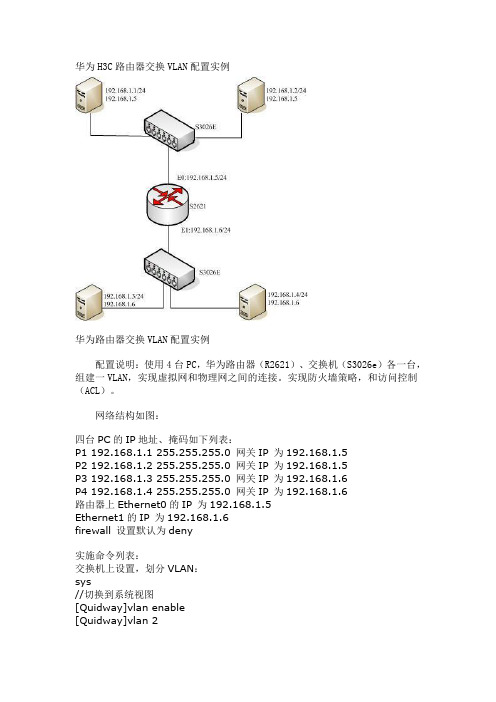
华为H3C路由器交换VLAN配置实例华为路由器交换VLAN配置实例配置说明:使用4台PC,华为路由器(R2621)、交换机(S3026e)各一台,组建一VLAN,实现虚拟网和物理网之间的连接。
实现防火墙策略,和访问控制(ACL)。
网络结构如图:四台PC的IP地址、掩码如下列表:P1 192.168.1.1 255.255.255.0 网关IP 为192.168.1.5P2 192.168.1.2 255.255.255.0 网关IP 为192.168.1.5P3 192.168.1.3 255.255.255.0 网关IP 为192.168.1.6P4 192.168.1.4 255.255.255.0 网关IP 为192.168.1.6路由器上Ethernet0的IP 为192.168.1.5Ethernet1的IP 为192.168.1.6firewall 设置默认为deny实施命令列表:交换机上设置,划分VLAN:sys//切换到系统视图[Quidway]vlan enable[Quidway]vlan 2[Quidway-vlan2]port e0/1 to e0/8[Quidway-vlan2]quit//默认所有端口都属于VLAN1,指定交换机的e0/1 到e0/8八个端口属于VLAN2[Quidway]vlan 3[Quidway-vlan3]port e0/9 to e0/16[Quidway-vlan3]quit//指定交换机的e0/9 到e0/16八个端口属于VLAN3[Quidway]dis vlan all[Quidway]dis cu路由器上设置,实现访问控制:[Router]interface ethernet 0[Router-Ethernet0]ip address 192.168.1.5 255.255.255.0 [Router-Ethernet0]quit//指定ethernet 0的ip[Router]interface ethernet 1[Router-Ethernet1]ip address 192.168.1.6 255.255.255.0 [Router-Ethernet1]quit//开启firewall,并将默认设置为deny[Router]fire enable[Router]fire default deny//允许192.168.1.1访问192.168.1.3//firewall策略可根据需要再进行添加[Router]acl 101[Router-acl-101]rule permit ip source 192.168.1.1 255.255.255.0 destination 192.168.1.3 255.255.255.0[Router-acl-101]quit//启用101规则[Router-Ethernet0]fire pa 101[Router-Ethernet0]quit[Router-Ethernet1]fire pa 101[Router-Ethernet1]quit。
![H3C配置实例]三层交换机VLAN间限制通讯](https://img.taocdn.com/s1/m/4397d73531126edb6f1a10a3.png)
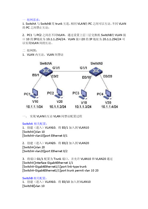
一组网需求:1.SwitchA与Switc hB用tru nk互连,相同VLAN的PC之间可以互访,不同VLAN的PC之间禁止互访;2.PC1与PC2之间在不同V LAN,通过设置上层三层交换机Sw itchB的VLAN接口10的IP地址为10.1.1.254/24,VLAN接口20的IP地址为20.1.1.254/24可以实现V LAN间的互访。
二组网图:1.VLAN内互访,VLAN间禁访一、实现VLAN内互访VLAN间禁访配置过程SwitchA相关配置:1.创建(进入)VLAN10,将E0/1加入到VLA N10[SwitchA]vlan 10[SwitchA-vlan10]port Etherne t 0/12.创建(进入)VLAN20,将E0/2加入到VLA N20[SwitchA]vlan 20[SwitchA-vlan20]port Etherne t 0/23.将端口G1/1配置为Tru nk端口,并允许VLAN10和VLA N20通过[SwitchA]interfa ce Gigabit Ethern et 1/1[SwitchA-Gigabit Ethern et1/1]port link-type trunk[SwitchA-Gigabit Ethern et1/1]port trunk permitvlan 10 20SwitchB相关配置:1.创建(进入)VLAN10,将E0/10加入到VL AN10[SwitchB]vlan 10[SwitchB-vlan10]port Etherne t 0/102.创建(进入)VLAN20,将E0/20加入到VL AN20[SwitchB]vlan 20[SwitchB-vlan20]port Etherne t 0/203.将端口G1/1配置为Tru nk端口,并允许VLAN10和VLA N20通过[SwitchB]interfa ce Gigabit Ethern et 1/1[SwitchB-Gigabit Ethern et1/1]port link-type trunk[SwitchB-Gigabit Ethern et1/1]port trunk permitvlan 10 20二、通过三层交换机实现VLAN间互访通过三层交换机实现VLAN间互访的配置SwitchA相关配置:1.创建(进入)VLAN10,将E0/1加入到VLA N10[SwitchA]vlan 10[SwitchA-vlan10]port Etherne t 0/12.创建(进入)VLAN20,将E0/2加入到VLA N20[SwitchA]vlan 20[SwitchA-vlan20]port Etherne t 0/23.将端口G1/1配置为Tru nk端口,并允许VLAN10和VLA N20通过[SwitchA]interfa ce Gigabit Ethern et 1/1[SwitchA-Gigabit Ethern et1/1]port link-type trunk[SwitchA-Gigabit Ethern et1/1]port trunk permitvlan 10 20SwitchB相关配置:1.创建VLAN10[SwitchB]vlan 102.设置VLAN10的虚接口地址[SwitchB]interfa ce vlan 10[SwitchB-int-vlan10]ip address 10.1.1.254 255.255.255.03.创建VLAN20[SwitchB]vlan 204.设置VLAN20的虚接口地址[SwitchB]interfa ce vlan 20[SwitchB-int-vlan20]ip address 20.1.1.254 255.255.255.05.将端口G1/1配置为Tru nk端口,并允许VLAN10和VLA N20通过[SwitchA]interfa ce Gigabit Ethern et 1/1[SwitchA-Gigabit Ethern et1/1]port link-type trunk[SwitchA-Gigabit Ethern et1/1]port trunk permitvlan 10 20。
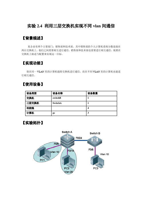
实验2.4 利用三层交换机实现不同vlan间通信【背景描述】某企业有两个主要部门:销售部和技术部,其中销售部的个人计算机系统分散连接在两台交换机上,他们之间需要相互进行通信,销售部和技术部也需要进行相互通信,现要在交换机上做适当配置来实现这一目标。
【实现功能】使在同一VLAN里的计算机能跨交换机进行通信,而在不同VLAN里的计算机也能进行相互通信。
【使用设备】【实验拓扑】【实现步骤】步骤1.在交换机SwitchA上创建vlan 10 ,并将0/5端口划分到vlan 10 中,创建vlan 20 ,并将0/15端口划分到vlan 20 中;SwitchA>enableSwitchA#config tSwitchA(config)#vlan 10SwichA(config-vlan)#name salseSwitchA(config)#interface fa 0/5SwitchA(config-if)#switchport access vlan 10SwitchA(config)#vlan 20SwichA(config-vlan)#name techSwitchA(config-if)#exitSwitchA(config)#interface fa 0/15SwitchA(config-if)#switchport access vlan 20SwitchA(config-if)#exit步骤2.把交换机SwichA和SwichB相连的端口定义为trunk模式SwitchA(config)#interface fa 0/24SwitchA(config-if)#switchport mode trunk!将fa0/24端口定义为tag vlan模式验证测试:验证fa0/24端口已被设为trunk模式SwitchA#show interface fa 0/24 switchportInterface Switchport Mode Access Native Protected VLAN lists---------- ---------- --------- ------- -------- --------- -------fa0/24 Enabled Trunk 1 1 Disabled All步骤3.在交换机SwichB上创建vlan 10,并将0/5端口划分到vlan 10中.SwichB(config)#vlan 10SwichB(config-vlan)#name salseSwichB(config-vlan)#exitSwichB(config)#interface fa 0/5SwichB(config-if)#switchport access vlan 10步骤4.把交换机SwichB和SwichA相连的端口定义为trunk模式SwichB(config)#interface fa 0/24SwichB(config-if)#switchport mode trunk验证测试:验证fa0/24端口已被设置为trunk模式SwichB#show interface fa 0/24 switchportInterface Switchport Mode Access Native Protected VLAN lists ---------- ---------- --------- ------- -------- --------- ----------fa0/24 Enabled Trunk 1 1 Disabled All步骤5.验证PC1与PC3能相互通信,但PC2和PC3不能相互通信。


拓扑图如图所示:本实验是实现pc1(192.168.10.1 vlan 10)与pc2(192.168.20.1 vlan 20)之间的通信。
配置:三层交换机:Switch(config)#interface fastEthernet 0/1Switch(config-if)#switchport trunk encapsulation dot1q(视情况而定)Switch(config-if)#switchport mode trunkSwitch(config-if)#exitSwitch(config)#interface fastEthernet 0/2Switch(config-if)#switchport trunk encapsulation dot1qSwitch(config-if)#switchport mode trunkSwitch(config-if)#exitSwitch(config)#vlan 10Switch(config-vlan)#exitSwitch(config)#vlan 20Switch(config-vlan)#exitSwitch(config)#interface vlan 10 创建相关vlan对应ip的网关地址Switch(config-if)#ip address 192.168.10.254 255.255.255.0Switch(config-if)#no shutdownSwitch(config-if)#exitSwitch(config)#interface vlan 20 创建相关vlan对应ip的网关地址Switch(config-if)#ip address 192.168.20.254 255.255.255.0Switch(config-if)#exitSwitch(config)#ip routing 配置完后开启三层交换机的路由功能。

H3C实验报告大全【含18个实验】4-配置vlan及vlan间路由配置vlan实验目录一.配置vlan、trunk1.配置H3C1的vlan,及vlan查看命令!![H3C1]display vlan[H3C1]display vlan all[H3C1]display port trunk[H3C1]display interface e0/4/32.配置H3C2的vlan3,解决默认只允许vlan1通过trunk链路[H3C1-Ethernet0/4/3]port trunk permit vlan all 4.gvrp相当与Cisco的VTP服务二.vlan间路由1.三层交换trunk和hybrid2.单臂路由一.配置vlan、trunkTotal 2 VLAN exist(s).The following VLANs exist: 1(default), 2详细的查看设备上vlan的情况[H3C1]display vlan allVLAN ID: 1 //vlan1的详细信息VLAN Type: static //vlan属于静态的,也就是说是手工创建的Route Interface: configuredDescription: VLAN 0001 //对vlan的描述Broadcast MAX-ratio: 100% //广播包在vlan链路占的百分比,可改Tagged Ports: none //标记的,如果串行接口不在此vlan中,那个接口将会出现在此处!Untagged Ports: //可以说是属于本vlan的接口Ethernet0/4/0 Ethernet0/4/1 Ethernet0/4/2Ethernet0/4/3 Ethernet0/4/4Ethernet0/4/5Ethernet0/4/6 Ethernet0/4/7VLAN ID: 2 //vlan2的详细信息VLAN Type: staticRoute Interface: configuredDescription: VLAN 0002Broadcast MAX-ratio: 100%Tagged Ports: noneUntagged Ports: none(s): spoofingInterfacePhysical Protocol IP AddressEthernet0/1/0up down unassigned[H3C1]display port trunkInterface PVID VLAN passing Eth0/4/3 1 1Port link-type: trunkVLAN passing : 1(default vlan) //默认只有vlan1通过VLAN permitted: 1(default vlan) //默认只允许vlan1通过Trunk port encapsulation: IEEE 802.1q //封装类型只会是IEEE802.1q%Nov 18 19:59:07:453 2010 H3C1 IFNET/4/LINK UPDOWN:Vlan-interface2: link status is UP%Nov 18 19:59:07:453 2010 H3C1 IFNET/4/UPDOWN:Line protocol on the interface Vlan-interface2 is UP ........................................ Done.[H3C1-Ethernet0/4/3] //此时vlan2接口就开启了[H3C2]interface e0/4/3[H3C2-Ethernet0/4/3]port trunk permit vlan all Please wait...%Nov 18 20:00:16:844 2010 H3C2 IFNET/4/LINK UPDOWN:Vlan-interface2: link status is UP%Nov 18 20:00:16:844 2010 H3C2 IFNET/4/UPDOWN:Line protocol on the interface Vlan-interface2 is UP ........................................ Done.[H3C2-Ethernet0/4/3][H3C1]display vlan allVLAN ID: 1VLAN Type: staticRoute Interface: configuredDescription: VLAN 0001Broadcast MAX-ratio: 100%Tagged Ports: noneUntagged Ports:Ethernet0/4/0 Ethernet0/4/1 Ethernet0/4/2Ethernet0/4/3 Ethernet0/4/4 Ethernet0/4/5Ethernet0/4/6 Ethernet0/4/7VLAN ID: 2VLAN Type: staticRoute Interface: configuredDescription: VLAN 0002Broadcast MAX-ratio: 100%Tagged Ports:Ethernet0/4/3 //本vlan通过哪个接口出去Untagged Ports: none[H3C1]display interface e0/4/3部分显示省略Port link-type: trunkVLAN passing : 1(default vlan), 2 //此时通过的vlanVLAN permitted: 1(default vlan), 2-4094 //此时允许通过的vlan是allTrunk port encapsulation: IEEE 802.1q<H3C1>display gvrp statisticsGVRP statistics on port Ethernet0/4/3GVRPStatus: EnabledGVRPRunning : YESGVRP Failed Registrations : 0GVRP Last Pdu Origin : 0000-5602-0003GVRP Registration Type : Normal二.vlan间路由1.三层交换--trunk和hybrid首先介绍trunk通过trunk使用三层交换实现vlan间路由是很简单的,只需要开启trunk链路并允许相应vlan 通过即可!与Cisco不同,不需要开启路由功能!!!!然后是hybridHybrid是h3c的,下面的实验就是hybrid的应用。

H3C三层交换机VLAN配置实例<H3C><H3C>dis cu#sysname H3C#radius scheme system#domain system#acl number 2011rule 0 denyrule 1 permit source 172.16.11.0 0.0.0.255 acl number 2012rule 0 denyrule 1 permit source 172.16.12.0 0.0.0.255 acl number 2013rule 0 denyrule 1 permit source 172.16.13.0 0.0.0.255 acl number 2021rule 0 denyrule 1 permit source 172.16.21.0 0.0.0.255 acl number 2022rule 0 denyrule 1 permit source 172.16.22.0 0.0.0.255 acl number 2023rule 0 denyrule 1 permit source 172.16.23.0 0.0.0.255 acl number 2031rule 0 denyrule 1 permit source 172.16.31.0 0.0.0.255 acl number 2032rule 0 denyrule 1 permit source 172.16.32.0 0.0.0.255 acl number 2033rule 0 denyrule 1 permit source 172.16.33.0 0.0.0.255 acl number 2041rule 0 denyrule 1 permit source 172.16.41.0 0.0.0.255 acl number 2042rule 0 denyrule 1 permit source 172.16.42.0 0.0.0.255 acl number 2043rule 0 denyrule 1 permit source 172.16.43.0 0.0.0.255 acl number 2080rule 0 denyrule 1 permit source 172.16.80.0 0.0.0.255 #vlan 1#vlan 11#vlan 12#vlan 13#vlan 21#vlan 22#vlan 23#vlan 31#vlan 32#vlan 33#vlan 41#vlan 42#vlan 43#vlan 80#interface Aux1/0/0#interface Ethernet1/0/1port link-type hybridport hybrid vlan 1 11 untaggedport hybrid pvid vlan 11packet-filter inbound ip-group 2011 rule 0packet-filter inbound ip-group 2011 rule 1 #interface Ethernet1/0/2port link-type hybridport hybrid vlan 1 12 untaggedport hybrid pvid vlan 12packet-filter inbound ip-group 2012 rule 0 packet-filter inbound ip-group 2012 rule 1 #interface Ethernet1/0/3port link-type hybridport hybrid vlan 1 13 untaggedport hybrid pvid vlan 13packet-filter inbound ip-group 2013 rule 0 packet-filter inbound ip-group 2013 rule 1 #interface Ethernet1/0/4port link-type hybridport hybrid vlan 1 21 untaggedport hybrid pvid vlan 21packet-filter inbound ip-group 2021 rule 0 packet-filter inbound ip-group 2021 rule 1 #interface Ethernet1/0/5port link-type hybridport hybrid vlan 1 22 untaggedport hybrid pvid vlan 22packet-filter inbound ip-group 2022 rule 0 packet-filter inbound ip-group 2022 rule 1 #interface Ethernet1/0/6port link-type hybridport hybrid vlan 1 23 untaggedport hybrid pvid vlan 23packet-filter inbound ip-group 2023 rule 0 packet-filter inbound ip-group 2023 rule 1 #interface Ethernet1/0/7port link-type hybridport hybrid vlan 1 31 untaggedport hybrid pvid vlan 31packet-filter inbound ip-group 2031 rule 0 packet-filter inbound ip-group 2031 rule 1 #interface Ethernet1/0/8port link-type hybridport hybrid vlan 1 32 untaggedport hybrid pvid vlan 32packet-filter inbound ip-group 2032 rule 0 packet-filter inbound ip-group 2032 rule 1 #interface Ethernet1/0/9port link-type hybridport hybrid vlan 1 33 untaggedport hybrid pvid vlan 33packet-filter inbound ip-group 2033 rule 0 packet-filter inbound ip-group 2033 rule 1 #interface Ethernet1/0/10port link-type hybridport hybrid vlan 1 41 untaggedport hybrid pvid vlan 41packet-filter inbound ip-group 2041 rule 0 packet-filter inbound ip-group 2041 rule 1 #interface Ethernet1/0/11port link-type hybridport hybrid vlan 1 42 untaggedport hybrid pvid vlan 42packet-filter inbound ip-group 2042 rule 0 packet-filter inbound ip-group 2042 rule 1 #interface Ethernet1/0/12port link-type hybridport hybrid vlan 1 43 untaggedport hybrid pvid vlan 43packet-filter inbound ip-group 2043 rule 0 packet-filter inbound ip-group 2043 rule 1 #interface Ethernet1/0/13#interface Ethernet1/0/14#interface Ethernet1/0/15#interface Ethernet1/0/16#interface Ethernet1/0/17interface Ethernet1/0/18#interface Ethernet1/0/19#interface Ethernet1/0/20port link-type hybridport hybrid vlan 1 80 untaggedport hybrid pvid vlan 80packet-filter inbound ip-group 2080 rule 0packet-filter inbound ip-group 2080 rule 1#interface Ethernet1/0/21#interface Ethernet1/0/22port link-type hybridport hybrid vlan 1 11 to 13 21 to 23 31 to 33 41 to 43 80 untagged #interface Ethernet1/0/23port link-type hybridport hybrid vlan 1 11 to 13 21 to 23 31 to 33 41 to 43 80 untagged #interface Ethernet1/0/24port link-type hybridport hybrid vlan 1 11 to 13 21 to 23 31 to 33 41 to 43 80 untagged #interface GigabitEthernet1/1/1#interface GigabitEthernet1/1/2#interface GigabitEthernet1/1/3port link-type hybridport hybrid vlan 1 11 to 13 21 to 23 31 to 33 41 to 43 80 untagged #interface GigabitEthernet1/1/4port link-type hybridport hybrid vlan 1 11 to 13 21 to 23 31 to 33 41 to 43 80 untagged #undo irf-fabric authentication-mode#interface NULL0#user-interface aux 0 7user-interface vty 0 4returnF100-C的设置问题回复方法一:F100-C恢复出厂设置,你以前的配置就会删除了,你可以重新配置你的固定IP配置固定IP配置实例:[H3C]dis cur#sysname H3C#firewall packet-filter enablefirewall packet-filter default permit#insulate#undo connection-limit enableconnection-limit default denyconnection-limit default amount upper-limit 50 lower-limit 20#nat address-group 1 218.94.*.* 218.94.*.*#firewall statistic system enable#radius scheme system#domain system#local-user wjmpassword simple wjmservice-type telnetlevel 3#acl number 2000 match-order autorule 0 permit source 192.168.0.0 0.0.255.255#interface Aux0async mode flow#interface Ethernet0/0ip address 192.168.0.1 255.255.255.0#interface Ethernet0/1#interface Ethernet0/2#interface Ethernet0/3#interface Ethernet1/0ip address 218.94.*.* 255.255.255.240#interface Ethernet1/1#interface Ethernet1/2#interface NULL0#firewall zone localset priority 100#firewall zone trustadd interface Ethernet0/0add interface Ethernet0/1add interface Ethernet0/2add interface Ethernet0/3set priority 85#firewall zone untrustadd interface Ethernet1/0add interface Ethernet1/1add interface Ethernet1/2set priority 5#firewall zone DMZset priority 50#firewall interzone local trust#firewall interzone local untrust#firewall interzone local DMZ#firewall interzone trust untrust#firewall interzone trust DMZ#firewall interzone DMZ untrust#ip route-static 0.0.0.0 0.0.0.0 218.94.*.*preference 60##user-interface con 0user-interface aux 0user-interface vty 0 4authentication-mode scheme#return华为交换机配置命令本文网址:/121555 复制华为QuidWay交换机配置命令手册:1、开始建立本地配置环境,将主机的串口通过配置电缆与以太网交换机的Console口连接。

实验10-三层交换机实现不同vlan间通信案例10 利用三层交换机实现不同vlan间通信【背景描述】某企业有两个主要部门:销售部和技术部,其中销售部的个人计算机系统分散连接在两台交换机上,他们之间需要相互进行通信,销售部和技术部也需要进行相互通信,现要在交换机上做适当配置来实现这一目标。
【实现功能】使在同一VLAN里的计算机系统能跨交换机进行通信,而在不同VLAN里的计算机系统也能进行相互通信。
【使用设备】【实验拓扑】设备名端口及所属VLANIP信息 IP地址网关Switch1 3560 Fa 0/24 默认VLANSwitch0 2960 Fa 0/24 默认VLANPC0 Fa 0/5 VLAN 10 192.168.10.10/24 192.168.10.254/24 PC1 Fa 0/15 VLAN 20 192.168.20.20/24 192.168.20.254/24 PC2 Fa 0/5 VLAN 10 192.168.10.30/24192.168.10.254/24 【实现步骤】步骤1.在交换机Switch1上创建vlan 10 ,并将0/5端口划分到vlan 10 中.Switch1>enableSwitch1#configure terminalSwitch1(config)#vlan 10Switch1(config-vlan)#name salesSwitch1(config-vlan)#exitSwitch1(config)#interface fastEthernet 0/5Switch1(config-if)#switchport access vlan 10Switch1(config-if)#exitSwitch1(config)#vlan 20Switch1(config-vlan)#name technicalSwitch1(config-vlan)#exitSwitch1(config)#interface vlan 20Switch1(config-if)#exitSwitch1(config)#interface fastEthernet 0/15Switch1(config-if)#switchport access vlan 20Switch1(config-if)#exit步骤2.把交换机Swich0和Swich1相连的端口定义为tag vlan模式SwitchA(config)#interface fastEthernet 0/24SwitchA(config-if)#switchport mode trunk!将F0/24端口定义为tag vlan模式验证测试:验证F0/24端口已被设为tag vlan模式 SwitchA#show interfaces fastEthernet 0/24 switchportInterface Switchport Mode Access Native Protected VLAN lists ---------- ---------- --------- ------- -------- --------- -------Fa0/24 Enabled Trunk 1 1 Disabled All步骤3.在交换机Swich1上创建vlan 10,并将0/5端口划分到vlan 10中. SwichB(config)#vlan 10SwichB(config-vlan)#name salseSwichB(config-vlan)#exitSwichB(config)#interface fastEthernet 0/5SwichB(config-if)#switchport access vlan 10步骤4.把交换机Swich0和Swich1相连的端口定义为tag vlan模式SwichB(config)#interface fastEthernet 0/24SwichB(config-if)#switchport mode trunk验证测试:验证F0/24端口已被设置为tag vlan模式SwichB#show interfaces fastEthernet 0/24 switchportInterface Switchport Mode Access Native Protected VLAN lists -------------------- --------- ------- -------- --------- ----------Fa0/24 Enabled Trunk 1 1 Disabled All步骤5.验证PC0与PC2能相互通信,但PC0和PC1不能相互通信。

配置通过VLANIF实现跨设备VLAN内通信组网图[Switch_1] interface gigabitethernet 0/0/1[Switch_1-GigabitEthernet0/0/1] port link-type trunk[Switch_1-GigabitEthernet0/0/1] port trunk allow-pass vlan 10[Switch_1-GigabitEthernet0/0/1] quit[Switch_1] interface gigabitethernet 0/0/2[Switch_1-GigabitEthernet0/0/2] port link-type trunk[Switch_1-GigabitEthernet0/0/2] port trunk allow-pass vlan 30[Switch_1-GigabitEthernet0/0/2] quit# 配置VLANIF10的IP地址为10.10.10.1/24,VLANIF30的IP地址为10.10.30.1/24。
[Switch_1] interface vlanif 10[Switch_1-Vlanif10] ip address 10.10.10.1 24[Switch_1-Vlanif10] quit[Switch_1] interface vlanif 30[Switch_1-Vlanif30] ip address 10.10.30.1 24[Switch_1-Vlanif30] quit# 配置OSPF基本功能。
[Switch_1] router id 1.1.1.1[Switch_1] ospf[Switch_1-ospf-1] area 0[Switch_1-ospf-1-area-0.0.0.0] network 10.10.10.0 0.0.0.255[Switch_1-ospf-1-area-0.0.0.0] network 10.10.30.0 0.0.0.255[Switch_1-ospf-1-area-0.0.0.0] quit2. 配置Switch_2# 创建VLAN10和VLAN30。