燃烧器控制器LFL1说明
- 格式:doc
- 大小:1.29 MB
- 文档页数:11
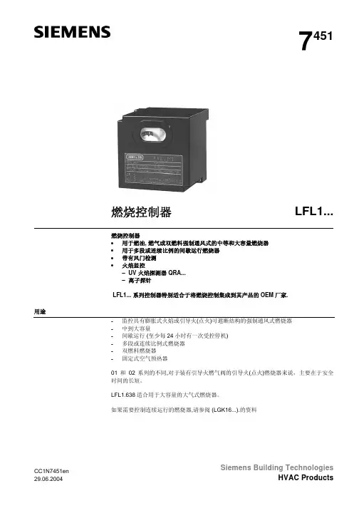
7451燃烧控制器LFL1...燃烧控制器•用于燃油, 燃气或双燃料强制通风式的中等和大容量燃烧器•用于多段或连续比例的间歇运行燃烧器•带有风门检测•火焰监控– UV 火焰探测器 QRA...– 离子探针LFL1... 系列控制器特别适合于将燃烧控制集成到其产品的OEM厂家.用途-监控具有膨胀式火焰或引导火(点火)可遮断结构的强制通风式燃烧器-中到大容量-间歇运行 (至少每24小时有一次受控停机)-多段或连续比例式燃烧器-双燃料燃烧器-固定式空气预热器01和02系列的不同,对于装有引导火燃气阀的引导火(点火)燃烧器来说,主要在于安全时间的长短。
LFL1.638适合用于大容量的大气式燃烧器。
如果需要控制连续运行的燃烧器,请参阅 (LGK16...).的资料Siemens Building Technologies CC1N7451en为避免人员伤害,财产损失和破坏环境,必须遵守以下警告注意事项!不要随意打开、干预或是改动控制器单元!•所有行为(装配、安装和服务工作等)必须由专业人员来完成。
•在LFL1…的连接区域改变任何接线之前,要使控制器单元完全与主要电源隔离(两级断开)。
•要给燃烧控制器的接线柱提供充足的保护,确保控制器不会受到电击危险。
•检查并确保线路连接正确。
•锁定复位按钮仅限手动(所需压力不超过10N),不要使用其他任何工具或是尖状物体。
•按动控制器单元上的锁定复位按钮或是远程锁定复位按钮不要超过10秒,否则会损坏控制器单元内的锁定继电器。
•坠落或撞击会影响到安全功能。
这样的控制器单元不能正常运作,即使外观看起来一点损害也没有。
•在使用UV探测器QRA..进行火焰监测时,必须注意那些发光源,例如卤素灯、焊接设备、特殊灯具、点火火花,还有X射线和伽马射线,会产生错误的火焰信号。
安装指南•确保遵守相关的国家安全规则•使用2个UV探测器QRA..时,要确保探测器彼此不能探测到。
安装注意事项•控制器单元和其他电缆必须与高压点火电缆分开安装排列•不要混淆相线和中线火焰探测器的电气安装排除干扰,在信号传输中避免干扰是很重要的。
燃烧器操作说明一、 初次使用,检查程序:遵循锅炉制造商的使用说明确认系统有足够多的水,油箱满油确认燃烧系统电控柜接线正确检查燃烧器电机转向检查温度、压力等传感器设定油路排气确保无空气检查油箱、油管、油泵充满油,喷嘴选择正确检查油路是否有泄露燃烧器处于开启位置,风门处于关闭位置程控器闭合,程控器处于启动位置二、 油路系统检查断开油路卸下电磁阀和喷嘴间连接启动燃烧器检查是否安程序控制器既定程序运行1、鼓风机气动2、风门伺服电机运行到最大位置3、风压监测正常4、风门伺服电机返回到点火位置5、点火6、油电磁阀打开7、安全时间后报警重新装好连接件三、 比例调节器回油与空气流量调节卸下风门伺服电机与比例调节器上的连接,启动燃烧器,点火后手动设定燃烧器负荷在最小位置,检查燃油和风量配合效果。
顺时针转动= 增加风量逆时针转动= 降低风量注意:燃烧器启动后调节风压开关,如果设定值过高,风压开关会自动保护,设定风压保护值一定要合理。
测量点火位置油消耗量1、通过流量表2、根据供油压力和喷嘴型号按照曲线图测算调节点火位置油量1、若喷油量过低,将伺服电机逐步增大到规定值2、若喷油量过高,现将最低油量限位开关调低,再逐步降低风门伺服电机,直至达到规定值。
调整过程中注意燃烧器的燃烧情况,如有必要从新调整。
调整满负荷耗油量逐步增大风门伺服电机的位置直至满负荷,调整过程中观察火焰燃烧情况,如有必要从新进行调整。
测量满负荷位置油消耗量1、通过流量表2、根据供油压力和喷嘴型号按照曲线图测算调节满负荷油流量若满负荷油量过多,减小风门伺服电机开度,直至达到规定值注意:不允许通过调节连杆降低油流量,以免影响低负荷燃烧状况。
若满负荷油量过低,首先增大限位开关的位置,然后调节伺服电机的开度,直至达到规定值,调节过程中注意观察火焰燃烧情况,如有必要从新进行调整。
风量调节风门伺服电机出厂设定值为:满负荷时全开,低负荷时全关,未达到最佳的燃烧效果,应从低负荷位置逐步调整燃油与风量的配比。
燃烧机控制器说明书一、引言燃烧机控制器是一种用于控制燃烧机的设备,通过对燃烧机的供油、供气、点火和燃烧过程进行监控和调节,确保燃烧过程的安全、高效和可靠。
本说明书将详细介绍燃烧机控制器的组成、工作原理、使用方法以及常见故障处理等内容。
二、组成1. 主控制单元:燃烧机控制器的核心部分,负责接收和处理各种输入信号,并输出控制信号给燃烧机的执行机构。
2. 输入模块:用于接收外部传感器的信号,如温度传感器、压力传感器等,以实时监测燃烧过程的状态。
3. 输出模块:用于输出控制信号给燃烧机的执行机构,如供油阀、供气阀等,以实现对燃烧过程的调节。
4. 显示屏:用于显示燃烧机的工作状态、参数设置和故障信息等,方便操作和维护人员进行监控和调试。
三、工作原理燃烧机控制器的工作原理基于燃烧过程的反馈控制原理,其主要步骤如下:1. 接收输入信号:燃烧机控制器通过输入模块接收外部传感器的信号,如温度传感器监测燃烧室温度、压力传感器监测燃气压力等。
2. 处理信号:主控制单元对接收到的信号进行处理,如与预设的参数进行比较,判断燃烧过程是否正常。
3. 输出控制信号:根据处理结果,主控制单元通过输出模块输出相应的控制信号给燃烧机的执行机构,如打开或关闭供油阀、供气阀等。
4. 监控和调节:燃烧机控制器持续监控燃烧过程的状态,并根据需要对参数进行调节,以确保燃烧过程的安全、高效和可靠。
四、使用方法1. 安装调试:按照燃烧机控制器的安装说明进行安装,并进行相应的调试工作,确保各部分连接正确、传感器灵敏可靠、执行机构正常运行。
2. 参数设置:根据燃烧机的要求和实际工况,设置燃烧机控制器的参数,如温度、压力、燃料比例等。
3. 运行监控:启动燃烧机控制器,并通过显示屏实时监控燃烧过程的状态,如温度、压力、燃烧效率等。
4. 故障处理:当燃烧机控制器显示异常或报警时,及时查找故障原因,并采取相应的措施进行处理,以保证燃烧机的正常运行。
五、常见故障处理1. 传感器故障:当燃烧机控制器接收到的传感器信号异常或失联时,应首先检查传感器的连接是否良好,如有问题则进行修复或更换。

燃烧器操作说明一、 初次使用,检查程序:遵循锅炉制造商的使用说明确认系统有足够多的水,油箱满油确认燃烧系统电控柜接线正确检查燃烧器电机转向检查温度、压力等传感器设定油路排气确保无空气检查油箱、油管、油泵充满油,喷嘴选择正确检查油路是否有泄露燃烧器处于开启位置,风门处于关闭位置程控器闭合,程控器处于启动位置二、 油路系统检查断开油路卸下电磁阀和喷嘴间连接启动燃烧器检查是否安程序控制器既定程序运行1、鼓风机气动2、风门伺服电机运行到最大位置3、风压监测正常4、风门伺服电机返回到点火位置5、点火6、油电磁阀打开7、安全时间后报警重新装好连接件三、 比例调节器回油与空气流量调节卸下风门伺服电机与比例调节器上的连接,启动燃烧器,点火后手动设定燃烧器负荷在最小位置,检查燃油和风量配合效果。
顺时针转动= 增加风量逆时针转动= 降低风量注意:燃烧器启动后调节风压开关,如果设定值过高,风压开关会自动保护,设定风压保护值一定要合理。
测量点火位置油消耗量1、通过流量表2、根据供油压力和喷嘴型号按照曲线图测算调节点火位置油量1、若喷油量过低,将伺服电机逐步增大到规定值2、若喷油量过高,现将最低油量限位开关调低,再逐步降低风门伺服电机,直至达到规定值。
调整过程中注意燃烧器的燃烧情况,如有必要从新调整。
调整满负荷耗油量逐步增大风门伺服电机的位置直至满负荷,调整过程中观察火焰燃烧情况,如有必要从新进行调整。
测量满负荷位置油消耗量1、通过流量表2、根据供油压力和喷嘴型号按照曲线图测算调节满负荷油流量若满负荷油量过多,减小风门伺服电机开度,直至达到规定值注意:不允许通过调节连杆降低油流量,以免影响低负荷燃烧状况。
若满负荷油量过低,首先增大限位开关的位置,然后调节伺服电机的开度,直至达到规定值,调节过程中注意观察火焰燃烧情况,如有必要从新进行调整。
风量调节风门伺服电机出厂设定值为:满负荷时全开,低负荷时全关,未达到最佳的燃烧效果,应从低负荷位置逐步调整燃油与风量的配比。
加热炉燃烧器PLC操作规程一、准备工作1、打开主燃料气手阀。
2、检查主燃料气供气压力在0.1MPa~0.4 MPa之间。
3、将室内控制柜面板上的自动/手动转换按钮打至自动。
急停按钮为按下状态,当需要紧急停车时,将停机按钮按箭头方向向右旋起即可。
4、将控制柜内中部电源空气开关依次合上,系统上电。
此时,燃烧器旋转风筒调风挡板0%开度,燃气切断阀、切断调节两用阀全关,放空电磁阀打开。
室内控制柜触屏上出现“六大队加热炉燃烧系统”主画面(如图1)。
图1对图1画面解释如下:“消音”按钮可以消除报警铃声。
“系统显示”按扭,按下该按扭将进入系统总监控画面(图2)。
“温度趋势”按扭,按下该按钮,进入趋势显示画面,可以显示一段时间内温度的变化情况。
“报警画面”按钮可以输出报警信息。
按下该按扭系统将进入报警画面。
该画面显示了故障的名称和报警的时间,并能够对历史报警信息进行保存,如果认为画面中存放的历史报警记录过多可进行报警记录的删除,按下“记录清除”按扭,清除历史报警信息。
“HELP”按钮可以进行在线帮助。
二、系统总启动1、点动图1中“系统显示”按扭,系统将进入八台燃烧器的总监控画面(如图2)。
图22、在触屏上点动图2中的“总启”,系统将按照预定程序控制燃烧器进行预吹扫、自动点火。
具体过程如下:风机开始吹扫,旋转内筒关闭。
吹扫结束后,各点火变压器依次上电拉弧,放空电磁阀关闭,快速切断阀(BV1)打开,点火枪点燃,此时火检装置进行火焰检测,当检测到火焰时,风阀打开至点火位,气阀打开至点火位,主燃料气进入主管线,燃烧器点火,点火成功时,图2中触屏上火焰状态指示灯依次由红色变成绿色。
(燃烧器正常点燃情况下,先对锅炉进行5分钟的预热,此时,对触屏的任何操作都无效。
)在上述过程中,任意一步未完成,均不会点火成功,此时报警铃响,触摸屏上显示相应的故障报警信息。
在依次启动1至8#燃烧器的过程中,无论哪台燃烧器出现故障报警,操作人员消除报警铃声后必须把画面切换到“报警画面”,点动“总启点火失败确认”按钮,消除故障报警图标,此时程序才能继续执行,点燃余下的燃烧器,报警图标不消除,程序将不在往下执行点燃余下的燃烧器。

Gas Burner Controls LFL1…燃气燃烧器程序控制器LFL1…系列Gas burner controls for gas, oil or dual-fuel forced draught burners of medium to high capacity. Multistage or modulating burners in intermittent operation *) with air pressure for checked supervised air damper control.燃气燃烧器程控器是用来控制大中型燃气、燃油或者是双燃料强制送风式燃烧器,间歇式运转的段式或比例式燃烧器。
*)以空气压力来监控所选择的风门调节控制器。
The gas burner controls are tested to EN 298 and CE-certified in compliance with the directives for gas-fired appliances and electromagnetic compatibility.燃气燃烧器程序控制器需要进行EN298 和CE认证的燃气装置和电磁兼容性的测试The LFL1... and this data sheet are intended for use by OEMs that integrate the burner controls in their products.这个数据表的目的是使制造商将燃烧器程序控制器合理的运用到产品中去。
*) For safety reasons, at least one controlled shutdown must take place every24 hours!出于安全考虑,每24小时至少一次必须进行强制停机USE:作用:The burner controls of the LFL1... range are designed for the control and supervision of forced draught gas burners of both expanding flame and interrupted pilot construction of medium to high capacity. They are universally applicable and can be used for bothmultistage and modulating burners as well as for dual-fuel burners and for burners of stationary air heaters (WLE to DIN 4794).LFL1…型燃烧控制器旨在对具有扩散式火焰和可遮断的点火大中型强制通风燃气燃烧器的控制和监督。

Technical InstructionsDocument No. 7451USLFL...Rev. 2 November 15, 2004LFL SeriesBurner Flame Safeguard ControlThe LFL… is a compact electro-mechanical primary flame safeguard control designed to provide burner sequencing, automatic igni-tion and continuous flame monitoring for gas, oil, and dual fuel, single burner applica-tions.The LFL… is applicable for on-off, multi-stage or modulating burners. The LFL… is designed for direct main burner ignition, intermittent or interrupted pilot operation.The LFL… integrates the flame amplifier,purge timer and sequencer in a single con-trol. Flame supervision is accomplishedusing UV sensor or flame rod detection.Features• Primary flame safeguard control • Visual sequence indication• Optional combustion air blower control • Optional postpurge • Preignition interlock• Continuous flame monitoring,including extraneous light detection • UV sensor functional test • Proven air switch function• Proven high fire purge interlock • Proven low fire ignition interlock • Direct main burner ignition,intermittent or interrupted pilot operation • Integrated flame amplifier• UV sensor or flame rod detector • Lockout alarm terminal• Local and optional remote reset •Burner off – economy position(fully closed air damper interlock) • Unit fuse and spare fuse provided11.15.2004Siemens Building TechnologiesHVAC ProductsControl interface2/12Siemens Building Technologies HVAC ProductsIndicator dial visible through front windowLockout indicator light visible through front windowThe LFL… reset buttonis integrated with the front window.During a lockout condition,pressing the window resets the LFL...Pressing * the window or remote resetduring normal operation will lockout the LFL…*Do not hold reset button for more than10 seconds! (Local or remote) , exceeding 10 seconds will damage control !Manually press the lockout reset button. Do NOT use any tools or pointed objects.Indicator dial provides symbolic information about the program sequence, the type of fault, and the point in the sequence where the fault occurred.The LFL… sequence is fixed and cannot be manually manipulated.Installation• All installation and commissioning work must be performed by qualified personnel. • The LFL… must be mounted in an electrical enclosure, typically in the control panel. • All wiring must comply with applicable electrical codes standards and regulations. • Before performing any wiring to the LFL…, remove and isolate all power. • High voltage AC wiring must not be installed in the same conduitas the flame detector wiring.• Maximum 10 A slow external fuse is required.• The LFL is not adversely affected by electromagnetic resonance. • Ground the LFL… wiring base. • Do not open or modify the LFL...• When UV flame supervision is used, other sources of radiation, such as halogenlamps, welding equipment, ignition sparks can produce erroneous flame signals.11.15.2004Ordering InformationTable 1Product Numbers110 Vac 50/60 Hz * LFL1.133-110V LFL1.333-110V LFL1.335-110V LFL1.635-110V220 Vac 50/60 Hz * LFL1.133 LFL1.335 LFL1.635 Timing descriptionPre-purge time 7.5 sec 26 sec 31 sec 55 secPilot trial for ignition (PTFI) 2.5 sec 4 sec 4 secMain trial for ignition (MTFI) 2.5 sec 4 secInterval from the beginning of MTFI2.5 sec 10 sec 10.5 secuntil release to modulationPost purge time 12 sec 15 sec 12 secFlame failure response time (FFRT) 1 sec*All times listed above are for 60 Hz operation. (Times for 50 Hz operation will be 20% longer.)Description Product NumberLFL Control unit Refer to Table 1 above(without wiring base)Wiring base AGM410490550Flame sensorUV (shown) QRA 4.Uforward looking 3/4” NPTUV Refer toQRA2… , QRA10 … Technical Instruction 7712Flame rod By othersWiring BaseThe wiring base provides the following:• 24 Terminals ______________• 3 Ground connections __________________--• 3 Neutral connections,connected to terminal 23/12 Siemens Building Technologies CC1N7451en HVAC Products 11.15.2004SpecificationsSupply voltage100 Vac –15 % ... 110 Vac +10 % 50/60 Hz ±6 % 220 Vac –15 % ... 240 Vac +10 % 50/60 Hz ±6 %Internal fuse 6.3 A (slow)External fuse Maximum 10 A (slow) Weight – LFL2.2 lb Weight – Wiring base 0.25 lb Power consumption3.5 VAMounting orientation No restrictionsGeneralTerminal 1 Line Maximum 5 A total load Terminal 2 Neutral N/ATerminal 3Alarm1 A pilot duty Terminals 4 to 5 Limit stringN/ATerminals 6 and 7Combustion AirBlowerMotor 4 FLA, 24 LRA or 1.6 A pilot duty Terminals 8, 9, 10, 11 Damper actuator N/A Terminals 12, 13, 14 Air flow interlock N/A Terminal 16 Ignition transformer 4 ATerminal 17 Pilot fuel valve Motor 4 FLA, 24 LRA or 1.6 A pilot duty Terminal 18 Main fuel valve Motor 4 FLA, 24 LRA or 1.6 A pilot duty Terminal 19 Main fuel valve Motor 4 FLA, 24 LRA or 1.6 A pilot duty Terminal 20 Damper actuator N/ATerminal ratings110VUL File: MH26134 Standard: UL372CSA Certificate: 1370843 Standard: CAN/CSA-C22.2 No 199-M89 FM File: J.I. 3003560Standard: FM7610110V & 220VCE File: CE-0085AP0001 Standard: DIN EN 298FCC Compliant Part 15 Class B - EmissionsApprovalsVibration 0.5G Environment Operation temperature range -5...+140 °F < 95 % relative humidityof water are not permitted!Environmental ratings4/12Siemens Building Technologies HVAC Products11.15.2004Specifications continued…Voltage – during burner operationVoltage – during start-up phase (flame circuit check) 330 Vac ±10 % 380 Vac ±10 %Required minimum UV sensor signal Typical UV sensor signal measurement 70 µA100-450 µALength of detector cable (run in a separate conduit from all other wiring)- Unshielded wire- Shielded cable, shield grounded to terminal 22 max. 300 ft max. 600 ftFlame supervision withUV sensor QRA...Voltage at the flame rod – during burner operationVoltage at the flame rod – during start-up phase (flame circuit check) 330 Vac ±10 % 380 Vac ±10 %Required minimum flame rod signal Typical flame signal measurement 6 µA20-100 µAShort-circuit current max. 0.5 mA Length of detector cable (run in a separate conduit from all other wiring)- Unshielded wire- Shielded cable, shield grounded to terminal 22 max. 250 ft max. 500 ftFlamesupervisionwithFlame rodElectrical connection notes for flame supervision• It is important to minimize electrical disturbance and signal loss.• Run flame signal wiring separate from all other wiring• Observe the length of detector cable as indicated above• The flame rod does not provide protection from electric shock• Locate the ignition electrode(s) and flame rod such that the ignition spark cannot arc to theflame rod (risk of electrical overload and damage to flame supervision circuit)• When using the QRA..., grounding of terminal 22 is required• Multiple UV sensors QRA... and/or flame rods can be connected in parallel• If separate flame sensors are used for pilot and main flame supervision,an interrupted pilot must be utilized5/12 Siemens Building Technologies CC1N7451en HVAC Products 11.15.2004Description of operating controls and their functionsLFL input (1) HOT and LFL input (2) NEUTRAL are used for control power, PowerReset and Alarm LFL output (3) ALARM, for alarm indicationLFL input (21) RESET, as show for reset and/or remote shutdownPressure or temperature activated, the operating limit switch (OLS),Operating limit OLSCloses , for burner start-up sequence to begin, and Opens , for a burner controlled shutdownPressure, temperature, or level activated, limit switches examples include: Limit switches LGP HGP LWSHigh LimitLow gas pressure (LGP) opens on low gas pressure High gas pressure (HGP) opens on high gas pressure Low water switch (LWS) opens on low waterThese limit and are considered either to be recycle or non-recycle, (manual reset), and are connected between; LFL output (5) RECYCLE and LFL input (4) RECYCLERecycle limit switches are used when it is desireable to stop the burner when the switch opens, and restart it again, automatically, when the switch closes again.Non-recycle limit switches are used when it is desireable to lockout the burner when the switch opens and prevent if from automatically restarting again. These switches must be manually reset, on the switch itself, as well as require you to push the reset button on the LFL to allow a new start-up sequence.The High Limit switch is almost always a non-recycle limit switch, and is usually connected to; LFL input (1) HOTNFPA 85, CSD-1 and UL795 require the HGP, LGP to cause a shutdown and be manually reset. Most burner / boiler insurance codes also require a LWS.The fuel proof of closure (POC) switch is integral to the fuel valve and activated by the valve mechanics. The POC prevents a burner start-up if the fuel valve is not in the proved close posi-tion.Fuel proof of closure POCLFL input (12) POC , is provided for this purpose. Note -This is a ‘Precondition for Startup’ and must be powered to start a sequence.Combustion air blower CABThe combustion air blower (CAB) provides combustion air to the burner. Not all installations re-quire the LFL to control the CAB. The LFL provides terminals for two options:LFL output (7) M2, powered after a 2 sec delay, and continues through postpurge. LFL output (6) M1, powered immediately, and stops prior to postpurge.The combustion air switch (CAS) is used to prove that combustion air is being provided. Most burner / boiler insurance codes require a CAS.Combustion air switch CASLFL input (14) COMBUSTION AIR PROVE , is connected to the normally open (NO) terminal of the CAS, and closes when air pressure is present.LFL input (13) COMBUSTION AIR TEST SW, is connected to the normally closed (NC) termi-nal of the CAS, to make sure the contacts have not welded.The LFL provides options for; interrupted pilot, intermittent pilot , and direct ignition as follows; LFL output (16) IGNITION , for the ignition transformerIgnitionLFL output (17) PILOT, for interrupted (pilot on only during ignition), or for intermittent (pilot on when burner is on)LFL output (18) MAIN DIR IGN , for the main fuel valve on direct ignition LFL output (19) MAIN PILOT , for the main fuel valve on piloted ignitionHigh fire purge inter-lock OPENGenerally, an actuator position switch, or a differential pressure switch, that is used to prove the actuator is at the high fire position. Some codes require the high fire position (open) be proved during prepurge .LFL output (9) OPEN , is provided to drive the actuator to this position. *See Note belowThis switch is also, generally, an actuator position switch, that is used to prove the actuator is at the low position. Some codes require the low fire (minimum) position be proved during ignition . Low fire start interlock MINIMUMLFL output (10) MINIMUM , is provided to drive the actuator to this position. *See Note belowThis switch is as well, generally another actuator position switch that proves it is at the fullyclosed (economy) position. This position is desired following post purge to minimize heat losses. Fully closed ECONOMYLFL output (11) ECONOMY , is provided to drive the actuator to this position. *See Note below*Note LFL input (8) FEEDBACK , is provided to confirm each of these positions.LFL output (20) RELEASE , enables an external load controlled and/or to indicate “Burner On“ Release to modulate Flame sensor inputLFL inputs (22) (23) (24) FLAME can be used for a UV sensor or flame rod6/12Siemens Building Technologies HVAC Products11.15.2004Wiring Diagram7/12 Siemens Building Technologies CC1N7451en HVAC Products 11.15.2004Sequence dial – OPERATIONSiemens Building Technologies HVAC Products11.15.2004Sequence dial – FAULT and LOCKOUT indication9/12 Siemens Building Technologies CC1N7451en HVAC Products 11.15.2004Program Sequence10/12Siemens Building Technologies HVAC Products11.15.2004DimensionsDimensions in inches11/12 Siemens Building Technologies CC1N7451en HVAC Products 11.15.2004Dimensions QRA4.UDimensions in inches12/12Siemens Building Technologies HVAC Products11.15.2004Represented By:POWER EQUIPMENT COMPANY 2011 Williamsburg RoadRichmond, VA 23231Ph. 804-236-3800Fx. 804-236-3882。
lfl1.333说明书lfl1.333说明书篇一:燃烧器控制器LF L1说明我国天然气和煤制气(原料为煤)资源丰富,且属于洁净能源,顾有着良好的社会经济效益。
燃气燃烧机符合我国产业政策,市场前景很好,大有发展前途。
然而在燃气燃烧机研制设计中,燃气特性—易燃、易爆及毒性,安全控制的首要问题。
下面介绍一下燃气燃烧机的安全控制要求:根据燃气在炉膛内的燃烧特性,对其安全控制要求内容主要有预吹风、自动点火、燃烧状态监控、点不着火的保护、熄火的保护、燃气压力高低限保护、空气压力不足保护、断电保护、预防燃气泄漏事故的措施等。
1. 预吹风燃烧机在点火前,必须有一段时间的预吹风,把炉膛与烟道中余气吹除或稀释。
因为燃烧机工作炉膛内不可避免地有余留的燃气,若未进行预吹风而点火,有发生爆炸的危险.必须把余气吹除干净或稀释,保证燃气浓度不在爆炸极限内。
预吹风时间与炉膛结构及吹风量有关一般设置为15-60秒2.自动点火燃气燃烧机宜采用电火花点火,便于实现自动控制。
可用高压点火变压器产生电弧点火,要求其输出能量为:电压≥3. 5K V、电流≥15mA ,点火时间一般为:2~5秒。
3.燃烧状态监控燃烧状态必须予以动态监控,一旦火焰探测器感测到熄火信号,必须在极短时间内反馈到燃烧机,燃烧机随即进人保护状态,同时切断燃气供给。
火焰探测器要能正常感测火焰信号,既不要敏感,也不要迟钝。
因为敏感,燃烧状态如有波动易产生误动作而迟钝,反馈火焰信号滞后,不利于安全运行。
一般要求从熄火到火焰探测器发出熄火信号的响应时间不超过0.2秒。
4.点不着火的保护燃烧机点火时,通入燃气,燃气着火燃烧。
点火动作要求发生在燃气通入前,先形成点火温度场,便于着火燃烧。
如果点不着火,火焰探测器感测不到火焰信号,燃烧机进入保护状态。
燃烧器使用说明书一、产品描述本燃烧器为XX公司生产的高效节能型产品,适用于工业生产中的各类燃烧作业。
本产品采用先进的燃烧技术,具备稳定的燃烧效果、可靠的操作性能和较低的燃料消耗。
请用户在使用本产品之前详细阅读本使用说明书,并按照说明进行正确操作。
二、安全注意事项1. 在操作本燃烧器之前,请确保将燃烧器放置在平稳的工作台面上,避免翻倒或摔坏。
2. 使用本燃烧器时,请确保操作环境通风良好,防止燃烧产生的有害气体滞留。
3. 在操作燃烧器时,请将手部、头部等暴露部位保持距离,以免造成烫伤或身体损伤。
4. 使用本燃烧器时,请穿戴相应的防护用品,如防护手套、防护面具等。
5. 在加注燃料时,请确保燃料不溅入燃烧器周围或操作人员身上,以防发生火灾或其他意外事故。
6. 使用本燃烧器时,请远离易燃物品和可燃气体,确保操作安全。
三、操作步骤1. 开启燃烧器电源,接通电源开关。
2. 调节燃烧器的气体供应和空气供给,使其达到标准燃烧状态。
3. 根据实际需求,设置燃烧器的燃烧参数,如燃料流量、燃气浓度等。
4. 检查燃烧器的点火设备和燃烧器火焰状态,确保正常点火和燃烧。
5. 观察燃烧器运行状态,如有异常情况出现,请立即停止使用,并进行必要的检修。
四、常见故障及处理方法1. 燃烧器无法点火:- 检查电源是否接通,是否有电压输出。
- 检查点火设备是否正常工作,如有故障请更换或修理。
- 检查燃料是否充足,燃气是否正常供应。
2. 燃烧器火焰不稳定:- 检查空气供给是否充足,调节空气阀门位置。
- 检查燃料供给是否正常,调节燃料阀门位置。
- 检查点火设备是否清洁,清理并调整点火设备位置。
3. 燃烧器产生异常噪音:- 检查燃烧器是否安装牢固,调整并固定燃烧器位置。
- 检查风机运转是否正常,如异常请更换或修理风机。
5. 燃烧器停机后仍有燃烧产物:- 检查燃气供应是否正常中断,若正常请检查燃烧器排气管道是否通畅。
五、保养与维护1. 定期清洁燃烧器和相关部件,去除积灰和杂质。
程控器LFL1.322控制点火及负荷调节说明1、程控器LFL1.322送电,若满足启动条件:安全联锁4和5连通、无空气压力检测即4和12接通、风门在关闭位置、报警已被复位后,内部控制回路接通使启动控制8脚得电,燃烧程控器开始自动运行。
2、如果风门不在关闭位置,程控器11脚得电,使连接的电机(2)脚得电。
风门打开时电机(2)~(22)断开(不在关闭位),而(2)~(12)接通。
电机(12)脚接至电机反转控制端,(12)得电后,电机反转,至风门关闭位置,(2)~(12)断开,电机停止反转。
此时(2)~(22)接通,电信号通过程控器11脚、电机(2)(22)反馈至程控器8脚,程控器启动。
3、程控器启动后,在t7时间段延时之后,程控器给7脚送电,启动风机(有后吹扫功能)。
如果选择程控器6脚控制风机,程控器送电后6脚马上得电启动风机,但程控器停止后无后吹扫。
4、程控器启动计时t16之后,程控器9脚得电。
程控器9脚接至电机(1)脚,在电机未转到最大风门位置前,(1)~(21)接通,(21)接至电机正转控制端。
(21)得电后,在t11时间段内,电机正转,一直转到(1)~(21)断开为止(风门最大位置)。
5、风机风门在最大位置,程控器计时t1,此段时间为前吹扫阶段。
此时电机反转控制端(12)~(2)接通,并连通到程控器11脚,但程控器11脚没电。
电机的(1)~(21)断开也使电机正转停止。
此时电机的(1)~(11)接通,电压信号通过(1)及连通的(11)、(22)、(24)把风门开至最大信号反馈给程控器的8脚。
6、经过t1时间段后,程控器9脚失电,并由程控器10替得电,接通电机点火位凸轮开关的(3)或(4)脚。
因为风门开至最大,所以(4)~(14)接通,而(14)与(2)、(2)与(12)连通,接电机反转控制端。
说明一下:这里(3)、(4)分别用于油、气两种燃料,(2)、(13)、(14)连通。
7、在t12时间段内,电机开始反转关小风门至点火位置,到点火位置后(4)~(14)断开电机停转,(4)接通(24)反馈给程控器8脚表示已到达点火位置。
LFL1…/LGK16…程控器工作原理一、燃烧器启动的前提1、程控器复位。
2、风门关闭。
关闭位置的限位开关“Z”(如QSN30)必须将端子11上的电信号输送到端子8上。
3、燃料阀门(BV)闭合位置的控制触点或其他具有类似检查功能的处于端子12与风压开关(LP)之间的触点必须闭合。
4、风压开关(LP)的常闭触点必须闭合(风压测试),即端子4必须输出电压。
5、气压开关(GP)及限制热动开关或压力开关(W)的触点也必须闭合。
二、启动程序1、A启动指令用“R”(即“R”关闭端子4与5之间的控制回路)2、(R)闭合,程控器开始运行,风机电动机接触器线圈通过端子6得到电压(仅预吹风)。
经过t7(2s)后,电动机或烟道通风机也通过端子7得到电压(预吹风或后吹风)。
3、完成t16(启动与风门开启指令间的时间间隔4-6s),经过端子9给出打开风门的控制指令,伺服电机运行期间,程控器不操作,因为端子8此时不带电,只有当风门完全打开和风门限制开关“A”(全开位置SQN30)给端子8供电并按程序工作,程控器才再启动。
4、t1—风门完全打开时的预吹风时间(额定风量)预吹风时间开始后不久,风压开关切换,选择端子4从端子13上断开,否则控制单元将有可能闭锁(空气压力检查开始),同时端子14必须带电并给点火变压器及燃料阀门供电。
5、在预吹风时间,火焰监测回路的安全功能也经受了试验(火焰继电器去激磁),如果继电器不能适当地起作用,控制闭锁。
6、完成预吹风时间后,控制单元通过端子10使风门挡板运行在低火焰位置,该位置是由风门控制器的辅助开关“M”的切换点确定的。
7、在运行时间,程控器再次停止运行,直到端子8从“M”得到电压为止。
一个短时间后,程控器的电机切换到控制单元的控制区。
因此从现在开始到端子8上的控制信号不再影响燃烧器的进一步启动(和以后运行)。
8、可调扩展火焰燃烧器t3—预吹风时间,然后靠端子18释放燃料。
t4—时间间隔(t2开始与端子19上阀门释放之间的时间间隔),t4完成后,端子19带电,这个端子为风门控制器电机辅助开关“V”上的燃料阀供电。
煤粉燃烧器<使用说明书>扬州市银焰机械厂尊敬的用户朋友:您好!感谢您及贵公司(厂)对“银焰”牌产品的信任和支持,选择使用“银焰”牌燃烧器装置,这是“银焰”人的集体荣耀。
“银焰”全体职工向您道声“谢谢”!如果您有什么建议和要求,请及时告诉我们,我们将把您的建议和要求作为下一步努力的目标和方向。
我们永远奉行“质量是生命,用户是上帝”的宗旨,竭诚为您提供周到、满意的服务。
扬州市银焰机械厂厂长:韦维通迅地址:江苏省扬州市产陵产业园银焰路9号电话:0514-*******-8811传真:0514-*******邮编:225006目录1、概述--------------------------------------12、结构简图及主要尺寸--------------------------------------23、结构及特点-------------------------------------------2-54、工作原理-----------------------------------------------65、安装---------------------------------------------------66、操作要求---------------------------------------------7-11 6.1操作------------------------------------------------7-9 6.1.1火焰形状的调整-----------------------------------7-9 6.1.2燃烧器位置的调整-----------------------------------9 6.2点火--------------------------------------------------10 6.3停窑--------------------------------------------------117、检查及保养---------------------------------------------128、常见故障及处理-----------------------------------------139、其它---------------------------------------------------141、概述煤粉燃烧器是水泥企业熟料烧成系统中的关键设备,其性能及操作的好坏关系到熟料产量、质量、能耗和环保,回转窑耐火砖的使用寿命长短等一系列问题,也就是说性能质量优良的煤粉燃烧器,将给企业带来巨大的经济效益,反之,将会带来无法估计的经济损失,因此煤粉燃烧器倍受水泥企业管理者和技术人员的高度重视!我厂在消化吸收国内外多风道煤粉燃烧器特点的基础上,集众家之长,研制的多风道燃烧器性能优越,可适合于各类回转窑,总体性能达到国际同类产品先进水平。
7454Gas Burner Control LFL1.148Gas burner control•for atmospheric gas burners in intermittent operation•flame supervision with ionization probe•supplementary Data Sheet N7451The LFL1.148 and this Data Sheet are intended for use by OEMs which integratethe burner controls in their products!Use-For the supervision of 1- or 2-stage atmospheric gas burners-For use with medium- to high-capacity burners-For intermittent operation (at least 1 controlled shutdown in 24 hours)-The gas burner has a connection facility for an auxiliary fan or flue gas fan (e.g. forcondensing boilers)Flame supervision is ensured by means of an ionization probe, 1 electrode is used for thefirst stage and 1 for the second stage. Changeover takes place automatically after re-lease of the second fuel valve.Building Technologies CC1N7454enWarning notesTo avoid injury to persons, damage to property or the environment, the followingwarning notes should be observed!Do not open, interfere with or modify the unit!•All activities (mounting, installation and service work, etc.) must be performed byqualified staff•For safety reasons – self-test of the flame supervision circuit, etc. – at leastone controlled shutdown must take place every 24 hours•Before performing any wiring changes in the connection area of the LFL1.148, com-pletely isolate the unit from the mains supply (all-polar disconnection)•Ensure protection against electric shock hazard by providing adequate protection forthe burner control’s connection terminals•Check to ensure that wiring is in an orderly state•Press the lockout reset button only manually (do not apply a force of more than 10 N)without using any tools or pointed objects•Do not press the lockout reset button on the unit or the remote lockout resetbutton for more than 10 seconds since this would damage the lockout relay in-side the unit•Fall or shock can adversely affect the safety functions. Such units must not be putinto operation, even if they do not exhibit any damageMounting notes•Ensure that the relevant national safety regulations are complied with•Connect the earthing lug inside the terminal base to burner ground using a screwwith a lockwasher or similarInstallation notes•Always run the high-voltage ignition cables separately while observing the greatestpossible distance to the unit and to other cables•Do not mix up live and neutral conductorsElectrical connection of the ionization probeIt is important to achieve practically disturbance- and loss-free signal transmission:•Never run the ionization cable together with other cables– Line capacitance reduces the magnitude of the flame signal– Use a separate cable of low capacitance•The ionization probe is not protected against electric shock hazard•Locate the ignition electrode and the ionization probe such that the ignition sparkcannot arc over to the ionization probe (risk of electrical overloads)2/83/8Commissioning notes• Prior to commissioning, check to ensure that wiring is in an orderly state• When commissioning the plant or when doing maintenance work, make the following safety checks:Safety check to be carried outAnticipated response a)Burner startup with ionization cable disconnectedLockout at the end of «TSA»Standards and certificatesConformity to EEC directives- Electromagnetic compatibility EMC (immunity) - Directive for gas appliances89 / 336 EEC 90 / 396 EECISO 9001: 2000 Cert. 00739 ISO 14001: 1996 Cert. 38233• Identification code to EN 298 A T L L X NCertified complete with plug-in base:Service notes•Each time a unit has been replaced, check to ensure that wiring is in an orderly state. Make the safety check in accordance with the «Commissioning notes»Disposal notesThe unit contains electrical and electronic components and must not be disposed of to-gether with domestic waste.Local and currently valid legislation must be observed.Mechanical designThe mechanical design of the LFL1.148 corresponds to that of the standard units of the LFL... range (refer to Data Sheet N7451).OrderingGas burner control , without plug-in base LFL1.148Plug-in base not included in the delivery, must be ordered as a separate item!Connection accessories for medium-capacity refer to Data Sheet N7230 burner controls- Plug-in base AGM410490550 with Pg11 threads for cable entry glands - Plug-in base AGM14.1 with M16 threads for cable entry glandsIonization probe to be supplied by thirdsTest unit KF8806 for burner control refer to Operating Instructions B7987 - For the simulation of faults- For checking the flame relay’s pull-in and drop-out values in the case of flame supervi-sion by ionization probe4/8Technical dataFor technical data – with the exception of the data listed below and the switching times of the switching mechanism – refer to Data Sheet N7451.Perm. length of detector cable- Normal cable, laid separately- Shielded cable, shielding connected to terminal 22, e.g. high-frequency cablemax. 50 m max. 100 mCapacity- Output on startup (without fanassistance)- Nominal outputany (with ignition < 120 kW) anyStorage DIN EN 60721-3-1 Climatic conditions class 1K3 Mechanical conditions class 1M2 Temperature range -20...+60 °C Humidity < 95 % r.h. Transport DIN EN 60 721-3-2 Climatic conditions class 2K2 Mechanical conditions class 2M2 Temperature range -40...+60 °C Humidity < 95 % r.h. Operation DIN EN 60 721-3-3 Climatic conditions class 3K5 Mechanical conditions class 3M2 Temperature range -20...+60 °C Humidity < 95 % r.h.Condensation, formation of ice and ingress of water are not permitted!FunctionIn terms of control program and flame supervision (including test of the flame supervision circuit), the functions of the LFL1.148 correspond of those of the standard units of the LFL.... range.There is a difference however in the control of actuator «SA» and of load controller «LR», especially with regard to the air damper position on startup and closing of the air damper during controlled shutdown.Supervision of the respective start position is accomplished via an auxiliary switch in the damper actuator whose contact must be included in the start control loop between termi-nals 4 and 5.It must be ensured that the current path between terminals 4 and 5 remains closed until controlled shutdown takes place.During controlled shutdown, the air damper is driven to the fully closed position via con-tact «Vlb» of the switching mechanism.Since the switching mechanism of the burner control does not continue to run until changeover of limit switch «z» in the air damper actuator occurs, the running time of actuator «SA» is optional.The pilot flame is supervised by ionization probe «ION1», the main flame by ionization probe «ION2».On completion of the ignition safety time «TSA», a flame signal must be present at terminal 23 «ION1». On completion of the second safety time «t9», a flame signal must also be present at terminal 24 «ION2».General unit dataEnvironmentalconditions5/8Control programIn the event of fault and lockout indication:◄ No startFor example: Start control loop interrupted via «SA»J Lockout due to a fault in the flame supervision circuit▼ Abortion of startup sequencebecause the auxiliary switch in actuator «SA»has cut the start control loop1 Lockout, because no flame signal was present on completion of the ignitionsafety time «TSA»2 Lockoutbecause no flame signal was present on completion of the secondsafety time▌ Lockout because the flame signal was lost during burner operation◄ Lockouton completion of the control program, due to extraneous light or a faultyflame signalFor example: Flame not extinguishedAfter the reset, the burner control’s switching mechanism first returns to the start position and then initiates a burner restart.Connection diagramConnection examples2-stage forced draft gas burner without load controller «LR» and without actuator «SA»Atmospheric gas burner without fan assis-tance, load controller «LR» and actuator «SA»6/8Basic diagramDo not press EK... for more than 10 seconds!Control programSB/R/WM1ZBV1BV2AB CD16716181923247/8Diagram of switching mechanismt1t3t6t7t4t5t8t10TSAt9t20AB CD a b a b a ba b a b a b XVXIV XIII XIIXI X IX VIII VII VI V IV IIIII I7454d01/0204a b 19169102011818152324127712a b a b a ba a a a bLegendAL Remote lockout indication → AlarmOutput signals of burner control AS Unit fuseRequired input signals AR Main relay with contacts «ar...» → Working relayBR Lockout relay with contacts «br...» A Start command given by the control thermostat BV... Fuel valve A-B Startup sequence d1/d2 Contactor or relay B Operating position of burner EK... Reset buttonB-C Burner operationION... Ionization probeC Controlled shutdown by «R»FR Flame relay with contacts «fr...» C-D Sequence mechanism runs to the end position after a GP Gas pressure switch controlled shutdown by «R»H Main isolatorD End position of burner → Corresponding to the start position L1Lockout warning lampLK Air damper Switching times in seconds LP Air pressure switch LR Load controller TSA Ignition safety time4 s M1/M2 Fan or burner motor t1 Waiting time or prepurge time 14 s NTC NTC resistort3 Preignition time 2 s R Control thermostat or pressurestat t4 Interval «BV1-BV2»8 s SAAir damper actuatort5 Interval between release of the 2nd fuel valve and the load a: Changeover limit switch for actuator’s OPEN position controller (if present) 10 s z: Changeover limit switch for actuator’s CLOSED positiont6 Postpurge time10 s SB Safety limit thermostat t7 Interval until voltage at terminal 7 is present 2 s Si External primary fuset8 Duration of startup program 36 s SM Synchronous motor of sequence mechanism t9 2ndsafety time for 2ndstage8 s V Flame signal amplifiert10 Interval until air pressure check is started6 s (1) Input for forced energizing of the flame relay during the t20 Steps of switching mechanism with no change in the 26 sfunctional test of the flame supervision circuit program → Idle steps (contact «XIV») and during «TSA» (contact «IV») WLimit thermostat or pressure switchZ Ignition transformer8/8DimensionsDimensions in mm27,527,5377,51037454m04/0305LFL1…©2005 Siemens Building Technologies Production GmbH Subject to change! Plug-in base AGM410490550 / AGM14.1。
7451ISO9001Gas Burner Controls LFL1...1燃气燃烧器控制器用于中等功率到大功率的燃气燃油或双燃料强制吹风燃烧器带风门挡板风压监控的间歇运行*多级或比例式燃烧器该控制器通过EN 298和CE 认证* 为安全起见控制器24小时内至少必须控制关停一次使用LFL1…燃烧器控制装置专为强制吹风燃烧器控制和监测设计可用于直接点火或带点火燃烧器的中高等功率燃烧器燃油燃气通用而且可以应用于固定预热空气燃烧器WLE 根据DIN 4794标准01系列和02系列的区别在于带点火燃气阀的点火燃烧器安全时间不同大功率的大气式燃烧的控制器选用LFL1.638如果燃烧器需要连续运行控制请参考LGK 16…技术资料机械构造该燃烧控制装置为插入式壳体和基座为抗震耐热黑塑料自锁指示器故障信号灯和复位按钮在该装置的视窗下该装置装备有可更换的保险丝和备用保险丝燃气燃烧器控制器2功能标准以下LFL…的特色提供了高水平的安全保障- 监测和光线测试在燃烧器时间结束后立即启动意思是在燃料阀开启状态或阀未关紧时经过该时间后立即自锁该测试到下一次燃烧器启动前吹扫时间结束后终止-火焰监测回路在每一次燃烧器启动时自动监测- 在后吹扫时监控燃料释放控制接触器是否黏着- 内置式保险丝保护接触器过载燃烧器控制-该装置允许燃烧器带或不带后吹扫- 风机电机电流小于4A 启动电流最大20A 可以直接连接- 单独的控制输出风门执行器的开关和最小-监测风门控制确保前吹扫期间有额定的风量检查启动位置关闭或最小低负荷位置开始时开和前吹扫时间结束后最小位置在执行器未驱动风门到达预定位置时燃烧器启动程序将中止- 启动前风压监测前吹扫直至控制关停阶段的风压监测功能测试-单独的点火燃料阀控制输出 在第2安全时间结束后切断- 2个燃料释放控制输出必要时有第3段控制输出或负荷控制- 系列1程控器直接点火时只需简单的措施便可将安全时间从2.5秒增加到5秒见工程注释提供更长的安全时间来适应当地安全法规- 当启动负荷控制时风门执行器的控制输出独立于其它控制部分电路-连接远程复位装置远程复位和远程紧急关停火焰监测火焰监测原理a带电离棒火焰探测器带或者不带接地线通常监测原理设计为点火火花不会干扰稳定火焰的监测回路如果探测器和燃烧器之间短路则会引起伪火焰信号b 带UV 火焰探测器QRA…系列燃油或燃气燃烧器见说明书7712c 如果同时使用电离棒火焰探测器和UV 火焰探测器如带点火燃烧器或燃气电子点火燃油燃烧器安装基坐电气连接- 安装位置和选择方位保护等级IP40- 24个连接端子- 2个辅助接线端子电路分开31和32- 3个地线端子- 3个中线端子预接至中线输入端子2- 14个松开的可插线端子8个在侧边6个在底边- 6个侧边松开的可插线端子3接线图燃烧器控制信号允许输入信号需要输入信号如果在该图案阴影部分时间无信号输入燃烧器将停机自锁图标见自锁指示工程注释开关保险丝地线等必须按照当地规章安装其它与阀组等的接线由燃烧器的制造商提供 相线和中线不可以弄反安全时间温控器手动复位如STB必须接入线路中 远程复位当按纽EK2只接到3号端子时为远程复位当只接到1时为紧急关断 所需12和4号端子及4和14号端子接触器开关容量决定于16…19号端子的负荷 风压开关如果风压开关没有接到风压监测回路LP 上时端子4必须接到端子12且端子6接到端子14端子13不用燃烧器的其它装置的控制接触器按以下方法接到端子12接触器必须仅在启动时闭合否则不会启动到端子4或5接触器必须在启动到控制关停阶段闭合否则不会启动或控制关停端子14接触器必须在前吹扫启动时间的最后一段到到控制关停阶段闭合否则将自锁无论长或者短吹扫都是这样• 直接点火接燃料阀如2级控制则接BV2以替代BV3••带点火燃烧器的燃料阀连接只能在以下情况下可以将燃料阀接到端子20- 主切断阀安全阀接到端子18或19和- 如果使用2级阀当1级由端子18或19控制关断时则为全关 进一步的风门挡板控制请参考接线示例在风门执行机构不带风门关闭限位开关z 时端子11必须接至端子10否则燃烧器不会启动可以同时使用电离棒和UV紫外光火焰监测装置4接线图LFL…接安全阀的接线图由燃烧器制造商提供a 风门挡板开位置限位开关AL 远程自锁报警装置警报器AR 主继电器工作继电器触点ar…AS 保险丝BR 自锁接触器触点br…BV…燃料阀bv…燃料阀关闭位置控制接触器d…接触器或继电器EK…自锁复位按钮FE 电离电流探测棒FR 火焰继电器触点fr…GP 燃气压力监测器H 主绝缘体L1故障信号灯L3运行就绪指示LK 风门LP 风压监测器LR 负荷控制器m 风门小位置辅助开关M…风机或燃烧器电机NTC NTC 电阻QRA…UV 电眼R 温控/压控RV 持续调整燃料阀S 保险丝SA 风门执行器SB 安全限位温度压力等SM 机械程序同步电机v 执行器上根据风门位置控制燃料释放辅助切换开关V 火焰信号放大器W 温控/压控限位z 执行器上风门关位置辅助限位开关Z 点火变压器ZBV 点火燃料阀•直接点火燃烧器••带点火燃烧器(1)UV 电眼运行电压输入(2)火焰监测回路功能测试XIV 接触器和安全时间t2IV 接触器必须带电输入图例全部参数3)不要按EK 超过10s5时序图t2‘ t3’ t4‘这些时间仅在程控器系列1中有如LFL1.335LFL1.635LFL1.638等它们不存在于系列2中这些型号中凸轮X 和VIII 开关同时动作运行模式上图显示了机械程序控制器的回路和控制时序A 启动指令通过安装的温控/压控R 发出A-B 启动程序B-C 燃烧器运行根据负荷控制LR发出负荷控制信号C 通过R 控制关停C-D机械机构运行回启动位置A后吹扫燃烧器关停之后只有11和12号端子得电且风门通过风门执行器限位开关z 控制位于关闭位置为进行监测和外在光线检测火焰监测回路也带电端子22/23和22/24燃烧器启动条件- 燃烧器不在自锁位置- 风门关闭关闭限位开关z 必须从11号端子输出电压到8号端子- 燃料阀bv…关闭位置控制接触器或其它端子12到LP 之间的类似控制功能必须关闭- 风压监测LP 检测常闭接触器N.C.必须闭合-燃气压力监测器GP 接触器和温控/压控限位W 必须闭合6启动程序 A通过R发出启动指令R 闭合4号和5号端子之间的回路机械程序开始启动同时风机电机通过端子6得电只有前吹扫经过t7时间后风机或排气电机持续通过7号端子得电带前吹扫和后吹扫t16时间结束后发出打开风门挡板指令在执行器运行期间机械程序暂停其间8号端子一开始机械程序就是通过该端子得电的没有任何电压输入直到风门完全打开后机械程序才继续往下运行t1前吹扫时间在风门全部打开状态在前吹扫时间火焰监测回路进行校正功能测试火焰继电器动作如果该继电器状态不正常燃烧器将自锁前吹扫程序开始后不久风压检测必须从13号打到14号否则燃烧器将自锁同时端子14必须得电点火变压器和燃料阀也从该回路得电前吹扫时间结束后通过端子10风门转到小火位置该位置由辅助切换开关m 控制在此期间机械程序再次暂停在此时间之后机械程序切换到燃烧器控制模式这就是为什么到8号端子的位置信号不再影响燃烧器的运行t5时间间隔t5时间结束后负荷控制器LR 通过端子20释放至此燃烧器启动程序结束机械程序也自行切断或运行空闲步骤如根据时间运行不改变接触器位置的步骤直接点火燃烧器t3t3‘预点火时间然后通过端子18释放燃料t2t2‘安全时间启动负荷在安全时间内火焰信号放大器的输入端22必须一直有信号而且持续到控制关停否则燃烧器将在此位置自锁t4t4‘到19号端子发出燃料释放启动主负荷的时间间隔t9第2段安全时间在第2段安全时间之后主燃烧器必须已经被点火燃烧器点燃该时间结束后之时17号端子立即失电点火燃气阀切断B 燃烧器运行位置B-C燃烧器运行在燃烧器运行阶段负荷控制器根据负荷要求控制伺服电机驱动风门到所需位置额定负荷的位置由风门执行器的辅助开关v 控制7C 控制关停当控制关停时燃料阀立即切断与此同时机械程序开始执行t6后吹扫时间风机接到端子7启动后吹扫时间后不久端子10接受到电压这样风门挡板被驱动到小位置在后吹扫时间结束后不久通过端子11发出信号风门完全关闭该信号在以下的燃烧器关闭程序中一直存在t13燃烧器后允许时间在此时间内火焰监测回路仍然必须接受到火焰信号才不致自锁D-A控制程序结束启动位置当机械程序经过t6时间后控制接触器处于启动位置火焰监测器和异常火焰检测再次启动在燃烧器关闭的情况下几秒钟的故障火焰信号将导致自锁短暂的UV 管点火脉冲如通常的辐射不会导致燃烧器自锁系列1燃烧器控制器仅有时间t2t3和t4警告y 在DIN 标准覆盖的地区安装必须符合VDE 标准特别是DIN/VDE 标准01000550和0722y 为防止火焰信号放大器过载在点火或运行中探测导线不可碰到点火火花y 当使用QRA…端子22必须接地y 监测可以同时使用电离棒FE 和紫外光电眼QRA…但为了安全起见除了第2段安全时间外一个时间只能有一种火焰监测装置起作用第2段安全时间后其中一个火焰监测装置必须停止工作也就是监测的火焰必须熄灭例如端子17控制的点火阀必须关闭y 允许并行连接2个UV-监测器QRA…y 燃气电路接线必须符合当地相关法规y LFL1…是安全装置不允许打开或改装y 运行前请仔细检查接线y 任何操作前必须保障该装置完全绝缘y运行前或更换过保险丝后必须检查所有安全功能y 确保安装有很好的电路冲击保护措施y 运行或维修时不允许有凝结水滴溅到燃烧器控制器上y电磁泄漏必须根据实际应用来检查是否符合要求8控制程序故障和自锁指示发生任何故障时机械程序将停止并指示自锁位置显示窗口的显示标记给出故障的类型无启动如有一个接触器未闭合燃烧器启动必备条件控制程序结束后有异常火焰信号如未熄灭火焰燃料阀泄漏火焰监测回路故障等 启动程序中断因为开启信号并没有通过限位开关a加到端子8端子67和15仍然带电直至故障消除P 自锁在风压控制中没有检测到风压 以后任何风压故障也会导致自锁 自锁火焰监测回路故障启动程序中断因为小火位置信号并没有通过限位开关m 加到端子8端子67和15仍然带电直至故障消除1自锁在第1安全时间结束后未检测到火焰信号2 自锁在第2安全时间结束后未检测到火焰信号_ 自锁在燃烧器运行过程中火焰信号消失如果在启动到前吹扫期间发生自锁没有显示标记这通常都是因为参数错误如错误的火焰信号如UV管自激放电自锁指示a-b 启动程序b-b‘ 空步无功能b(b‘)-a 后吹扫程序LFL1…系列1 LFL1…系列2• 安全时间 直接点火•• 安全时间 点火燃烧器点火当发生自锁时可立即通过复位按钮解锁复位后或者排除导致控制关停的故障机械程序总是转至启动位置根据控制程序仅有7910和11号端子得电只有如此燃烧器控制才开始新的燃烧器启动程序9接线范例双倍点火时间直接点火燃烧器仅限于使用系列1根据该回路接线方法17和18号端子短接预吹扫时间减少到50%仅在安装当地标准允许情况下才可以延长该安全时间燃烧器无风门在燃烧器无风门的情况下或风门不受程控器控制和监控端子8必须接到端子6否则燃烧器不能启动2段火直接点火燃烧器负荷控制只有开/关控制风门在燃烧器停机时为关闭位置根据单线控制原理风门执行器SA 如SQN3… 其它接线请参考相关接线图7451a10/129510比例式直接点火比例负荷控制器带独立电路的开和关控制接触器燃烧器关停时风门关闭其它接线请参考接线图2段火带点火燃烧器程控器系列1控制和监测燃烧器关停时风门关闭其它接线请参考接线图Mains voltage AC 220 V - 15 % ... 240 V + 10 %Required switching capacity of switching devices AC 100 V - 15 % ... 110 V + 10%– Between terminals 4 and 5 1 A, AC 250 V – Between terminals 4 and 12 1 A, AC 250 V Mains frequency 50 Hz - 6 % ... 60 Hz + 6 %– Between terminals 4 and 14Power consumption 3 VA depending on load on terminals 16 to 19,1 A min., AC 250 V Unit fuse,built-in T6, 3H 250 V to IEC 127Permissible mounting position optional Degree of protection IP40Unit fuse, external 16 A max., slow Weight Radio interference – Burner control approx. 1000 g protection N to VDE 0875– Baseplate approx. 165 g Permissible input current at terminal 1 5 A to VDE 0660 AC 3Perm. loading of control terminals 4 A to VDE 0660 AC 3Environmental conditions CE conformity - Transport IEC 721-3-2 According to the directives of the European Community Climatic conditions class 2K2 Electromagnetic compatibility EMC Temperature -50...+70 °C 89/336 EEC incl. 92/31 EEC Humidity < 95 % r.h. Gas appliance directive 90/396 EEC Mechanical conditions class 2M2Emissions EN 50081-1- Operation IEC 721-3-3Immunity EN 50082-2 Climatic conditions class 3K5 Temperature -20...+60 °C Humidity < 95 % r.h.Condensation, formation of ice and ingress of water are not permitted.Voltage at detector electrode Maximum permissible length of detector cable – Operation AC 330 V ± 10 %– Normal cable, laid separately ²) 80 m – Test AC 380 V ± 10 %– Shielded cable,140 m e.g. high frequency cable; shielding connected to Short-circuit current 0.5 mA max. terminal 22Minimum ionization current required 6 µA Recom. range of measuring instrument 0 ... 50 µA Supply voltage Weight– Operation AC 330 V ± 10 %– QRA260 g – Test AC 380 V ± 10 %– QRA10450 g Minimum detector current required ³)70 µA Identification code to EN298:all types (except LFL1.148)FBLLXNMaximum detector current– Operation 680 µA– Test 1000 µA ¹)Max. perm. length of detector cable– Normal cable, laid separately ²) 100 m– Shielded cable,200 me.g. high frequency cable; shielding connected toterminal 22¹)During the pre-purge time with increased test voltage: self-ignition and extraneous light test²)Laying in multi-core is not permitted³)For better reading, connect an electrolytic capacitor of 100 µF, DC 10 V, parallel to the measuringinstrument, +pole of the instrument connected to terminal 23Technical data Ionization current supervision UV supervision 11技术参数电离电流监测UV 紫外光监测t1前吹扫时间包含风门开启时间t2安全时间t2’安全时间或当燃烧器带点火燃烧器时第1安全时间t3预点火时间短点火变压器接16号端子t3’预点火时间长点火变压器接15号端子t4t2启动到端子19燃料控制阀释放时间间隔t4’t2’启动到端子19燃料控制阀释放时间间隔t5t4终点到负荷控制或端子20释放之间的时间间隔t6后吹扫时间(电机M2)t7发出启动指令到7号端子得电(风机电机M2启动延迟时间)t8启动时间无t11和t12t9当燃烧器使用点火燃烧器时第2段安全时间t10启动到风压监测间隔时间不含风门运行时间t11风门转到开位置运行时间t12风门转到小火位置运行时间时间标志t13燃烧器后允许时间t16风门开指令时间间隔t20燃烧器启动后机械程序自行切断时间间隔12开关时间以秒计供电频率为50 Hz 如果使用60 Hz 供电时间缩短约20%1 供电100…110V 定货时注明~110V 供电2 根据德国极性保护标准所做的修改型号 AGM30LFL1.122 ¹)LFL1.133 ¹)LFL1.322 ¹)LFL1.333 ¹)LFL1.335 ¹)Series 02Series 02Series 02Series 02Series 01 Preferred types for / in:Flash Flash D (also A GB steam steam for WLE)D generator generator F t11093631.537.5t22323 2.5t2´−3−−5t343465t3´−−−− 2.5t466101212.5t4´−−−−15t543101212.5t61014.5121815t72323 2.5t83029607278t923235t106681210t11optional t12optional t1643465t131014.5121815t203260−2722.5LFL1.622 ¹)LFL1.635 ¹)LFL1.638Series 02Series 01Series 01 F B Large atmospheric I NL ²)burner t16667.567.5t22 2.5 2.5t2´−55t3455t3´− 2.5 2.5t41012.512.5t4´−1515t51012.512.5t6121515t72 2.5 2.5t896105105t9257.5t1081010t11optional t12optional t16455t13121515t20−−−订货13尺寸基座AGM410490550LFL…带基座 AGM410490550。
我国天然气和煤制气(原料为煤)资源丰富,且属于洁净能源,顾有着良好的社会经济效益。
燃气燃烧机符合我国产业政策,市场前景很好,大有发展前途。
然而在燃气燃烧机研制设计中,燃气特性
—
易燃、易爆及毒性,安全控制的首要问题。
下面介绍一下燃气燃烧机的安全控制要求:根据燃气在炉膛内的燃烧特性,对其安全控制要求内容主要有预吹风、自动点火、燃烧状态监控、点不着火的保护、熄火的保护、燃气压力高低限保护、空气压力不足保护、断电保护、预防燃气泄漏事故的措施等。
1.预吹风
燃烧机在点火前,必须有一段时间的预吹风,把炉膛与烟道中余气吹除或稀释。
因为燃烧机工作炉膛内不可避免地有余留的燃气,若未进行预吹风而点火,有发生爆炸的危险.必须把余气吹除干净或稀释,保证燃气浓度不在爆炸极限内。
预吹风时间与炉膛结构及吹风量有关一般设置为15-60秒
2.自动点火
燃气燃烧机宜采用电火花点火,便于实现自动控制。
可用高压点火变压器产生电弧点火,要求其输出能量为:电压≥3.5K V、电流≥15mA,点火时间一般为:2~5秒。
3.燃烧状态监控
燃烧状态必须予以动态监控,一旦火焰探测器感测到熄火信号,必须在极短时间内反馈到燃烧机,燃烧机随即进人保护状态,同时切断燃气供给。
火焰探测器要能正常感测火焰信号,既不要敏感,也不要迟钝。
因为敏感,燃烧状态如有波动易产生误动作而迟钝,反馈火焰信号滞后,不利于安全运行。
一般要求从熄火到火焰探测器发出熄火信号的响应时间不超过0.2秒。
4.点不着火的保护
燃烧机点火时,通入燃气,燃气着火燃烧。
点火动作要求发生在燃气通入前,先形成点火温度场,便于着火燃烧。
如果点不着火,火焰探测器感测不到火焰信号,燃烧机进入保护状态。
从点火到进入保护状态的时间要适当,既不能过短也不能过长。
若过短,来不及形成稳定火焰;过长,点不着火时造成大量燃气时入炉膛。
一般要求在通入燃气2-3秒,燃烧机对火焰探测器感测的火焰信号进行判断,未着火则进入保护状态,着火则维持燃烧。
5.熄火保护
燃烧机在燃烧过程中,若意外熄火,燃烧机进入保护状态。
由于炉膛是炽热的.燃气进入易发生爆燃,故须在极短时间内进入保护状态,切断燃气供给。
从发生熄火到燃烧机进人保护状态,该过程的响应时间要求不超过1秒。
6.燃气压力高低限保护
燃气燃烧机稳定燃烧有一定范围,只允许燃气压力在一定范围内波动。
限定燃气高低压的目的是确保火焰稳定性:不脱火、不熄火也不回火,同时限定燃机的输出热功率,保证设备安全经济运行。
当燃气压力超出此范围,应锁定燃烧机工作。
燃烧机设计一般用气体压力开关感测压力信号,并输出开关量信号,用以控制燃烧机的相应工作。
7.空气压力不足保护
燃气燃烧机设计热强度大,其燃烧方式采用鼓风强制式。
如果风机发生故障造成空气中断或空气不足,立即切断燃气,否则会发生炉膛爆燃或向风机回火。
因此在提高风机质量的同时,燃气控制必须与空气压力连锁,当空气压力不足时,应立即切断燃气供给。
一般用气体压力开关感测空气压力信号,并输出开关量信号,用以控制燃气电磁阀的相应工作。
8.断电保护
燃烧机在工作过程中突然断电,必须立即切断然气供给,保护设备安全。
燃气控制电磁阀必须是常闭型的,一旦断电,自动关闭切断燃气供给。
电磁阀关闭响应时间≤5s.
9.预防燃气泄漏事故的措施
燃气泄漏包括二个方面,一指燃气通过管路向环境泄漏,二指燃气通过电磁阀阀芯端面向炉内泄漏。
环境泄漏可能引起人员中毒、工作现场爆炸事故,必须高度重视。
首先确保管路密封,定期对管路检漏,若管路泄漏须排除方可继续使用;其次,避免造成中毒与爆炸的燃气浓度,要求工作现场通风良好:配置永久性的通风孔和强制通风装置;另外,要求工作现场禁止烟火、电气件防爆。
炉内泄漏可能引起炉内爆炸。
解决炉内泄漏问题有三个途径:一是加强预吹风时间和吹风量,吹除或稀释炉内燃气;二是燃气管路采用二个电磁阀串联结构,提高系统安全性;三是使用管路泄漏检测装置,在点火前对燃气管路进行检测,若燃气泄漏达到一定量即锁定燃烧机工作。
预防燃气泄漏措施属外围控制,一般不纳入燃烧机本体控制。
(注:专业文档是经验性极强的领域,无法思考和涵盖全面,素材和资料部分来自网络,供参考。
可复制、编制,期待你的好评与关注)。