MACKIE_ProFX8、ProFX12_中文说明书(简体中文版)
- 格式:pdf
- 大小:11.59 MB
- 文档页数:32

1.电池手柄①连接点②轨道③释放滑块④安全开关⑤触发点⑥充电指示灯(不是PH09)⑦LED 灯(不是PH09)⑧带环2.特点和操作方法1.请更改驱动方向或者释放这个安全触发点。
当你更换电池或者是其他配件的时候移动到中心位置。
2.阅读手册所有客户用这个机器的时候首先要阅读和理解所有的资料和警告标签关于这台机器和其他材料的。
3.保护视力,听力和呼吸。
4.穿戴合适的衣服。
5.按下触发器,通过压力来改变控制速度。
6.旋转开关激活LED 工作灯。
7.在这个方向滑动双面到一定位置来释放电池手柄。
8.按下这个地方可显示电量。
9.展开这个带环从手柄的前方,直到click这个位置。
然后再收回到这个click位置。
3.安装电池手柄插入电池手柄对齐电池手柄上的轨道插入工具里面或者是充电直到感觉到他们完全契合和平整。
移开电池手柄握住和滑动两个滑动开关,将电池手柄从机器里拔出来。
LED 指示灯第一个是红灯,第二个是黄灯,第三个是绿灯。
满电的时候是绿灯亮还有一半电池的时候是黄灯亮电池电量低的时候是只有红灯亮。
改变电量按下在电池边上的第一个黑色按钮,他就会显示现在的电量是多少。
红色的灯说明现在电量很低。
红色加黄色的灯说明电池还能维持一段时间。
红色加黄色加绿色一块显示说明是满电。
更换充电过程是这些灯来回循环的过程,先是红灯,黄灯,绿灯然后又红灯,黄灯,绿灯,然后又红灯,这样来回循环下去直到电池充满电。
当所有的灯都亮了不来回的闪了,电池就充满电了。
警告指示温度保护当高温的时候电池的红色灯将不停的显示,这预示着我们要把温度降到75摄氏度或者167 华氏温度。
电流保护高电量消耗导致电池内的电压低(例如工具被卡住时),红色的灯会快速闪烁10秒,打开卡住之物,重新启动该工具。
充电注意:电池充电必须提供充足的电量,确保电池能完好的充满电,第一次使用前必须给电池充满电。
电池要保持干燥,不要进水。
必须有特定的充电器给电池充电或者其他可以代替的东西。
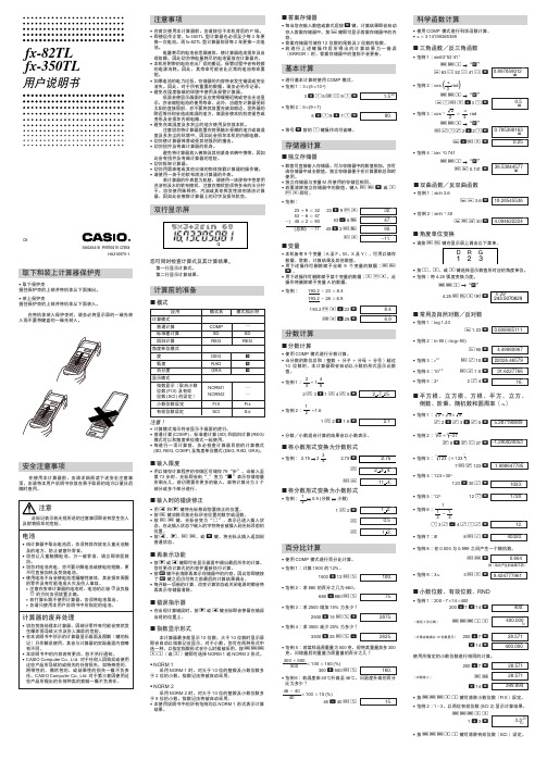

是一个FX-82ES计算机,按下MODE键会显示出三个功能。
同时按下SHIFT-7-ON键(此功能用于出厂测试计算器,嘿嘿),并连按多次SHIFT后,会出现如(图二)所显示的内容。
其中P3便代表FX-82ES的模式,现在我们就要将其修改为FX-991ES的模式。
图(二)图(三)关闭计算器,拆开计算器,可以看到如(图三)的电路板。
找到P4引脚,可以看到当中有条裂缝,用指甲将上面的(尤其是裂缝中的)氧化层刮去,随后用软性铅笔(如2B)在裂缝上涂满,确保裂缝中有足够的碳粉可以导通P4引脚后。
打开计算器,按下MODE,可以看到如图(四)的画面,变成8种模式功能,原来只有3种)这说明你的计算器改装成功了。
图(四)同时按下SHIFT-7-ON键,并连按多次SHIFT后,可以看到如(图五)的画面,P?说明你的计算器连接了两个P引脚,变得十分怪胎了,不过这并不影响使用。
其实,P引脚是用来设置计算机型号的。
卡西欧公司从成本上考虑,将一些计算器使用相同的电路板,只是通过P来设置型号。
可以看到FX-82ES计算器的P3引脚是连通的,而其它的引脚都有一条裂缝。
如果你有兴趣,可以尝试连通其它的,会出现不同的功能,不过连接P4后的功能是最多的,与FX-991ES的功能完全一样。
(如果错了,橡皮擦擦了就好了)改装后的计算器有部分按键与原计算器不同,这里提供了对照表(图六)希望注意。
附:1.卡西欧FX-991ES说明书下载地址:/CALC/DOWNLOAD/CN/MANUAL/2.卡西欧FX-82ES大家可以去本地的文具批发市场和是小一些的商场,和是网络商店,你可以去里面逛逛,一般批发价为48元,零售价为55元左右(如果是大商场80多)。
而FX-991ES的价格为120-160元之间(如果是大商场300多)3.考研规定FX-911ES计算机是肯定能用的,FX-82ES是更不用说了。
所以改装的FX-82ES考研不管能不能用,自己用都是最不错的选择。

水果FL12官方说明书中文版通道机架与步进音序器通道机架可以放置能产生声音的乐器(instruments),以及内部的自动化控制发生器(automation)。
每个片段(pattern)都能够使用机架中的所有乐器,也就是说,所有片段使用的都是相同的乐器配置,这与其他音序器把片段限制在单独乐器上不同。
音乐数据可以通过步进音序器和钢琴卷帘窗来编辑。
每个乐器都有一个自己的通道按钮(Channel Button),每个通道的音频被送入一个调音台通道(Mixer Track)来做效果器处理和混音。
当添加或者移除乐器的时候,通道机架的高度会动态改变。
通道按钮可以打开乐器通道设置(Instrument Channel Settings,在这里设置送入哪个调音台通道),也能打开对应的通道卷帘窗。
步进音序器(Step Sequencer)是一个基于片段的(pattern-based)栅格式音序器,适合创建鼓循环和简单的旋律。
所有通道的音符和自动化控制数据组成一个“片段(pattern)”。
片段包括来自钢琴卷帘窗、步进音序器、自动化控制数据的信息。
通过下图中所示的片段选择器(15,Pattern Selector)可以切换片段,当片段序号改变的时候,注意通道机架中的片段外观也改变了,切换到了对应的片段的外观。
片段被设计成能够在编排窗口(Playlist)中作为片段贴片(Pattern Clip)来进行编排从而组成一首歌。
概览通道机架中每一行的控件都属于一个单独的乐器通道。
从左到右是:声象(Pan)、音量(Volume)、通道按钮(Channel Button,点击打开乐器界面),接下来,根据通道是如何设置的,可能显示的是步进音序器的一排按钮(Step Sequencer buttons)或者钢琴卷帘窗的预览(下图中第一行)。
注意:(阳光注:关于同时打开多个乐器界面的问题)当Options > General settings > Auto select linked modules是(选项 > 通用设置 > 自动选择链接模块):ON 打开状态:按住alt点击通道按钮可以同时打开多个乐器界面。


PhoenixPro用户指南 V e r s i o n:1.00C r e a t e:2009-02-03目录序言 (1)第一部分软件简介 (2)第二部分界面说明 (3)第三部分操作说明 (5)3.1安装USB驱动 (5)3.2软件安装 (5)3.2.1 软件的完整性检查 (5)3.2.2 安装软件 (6)3.3量产准备工作 (8)3.3.1 使用HUB (8)3.3.2 不使用HUB (10)3.4软件启动 (10)3.4.1 打开量产软件 (10)3.4.2 配置软件 (10)3.4.3 启动软件 (11)3.5投入设备量产 (12)3.6软件关闭 (16)3.7软件升级 (17)第四部分注意事项 (19)4.1量产之前需注意的事项 (19)4.2量产过程中需注意的事项 (19)4.3出错处理 (20)第五部分USB驱动程序安装 (23)附A 常见问题及解决方案 (26)附B 快速操作指南 (27)序言1序言此手册是为PhoenixPro量产工具使用说明,它由软件简介、界面说明和操作指南等组成,全面介绍了量产工具的流程和使用方法。
本文档使用范围仅限于PhoenixPro量产工具使用用户。
文档结构:z软件简介z界面说明z操作说明z注意事项z驱动程序安装z FAQz快速指南2第一部分软件简介第一部分软件简介PhoenixPro量产工具通过样机与PC的连接的USB通道下载固件包到样机中。
整个量产工具由认证文件、固件包和量产软件组成,认证文件和固件包默认情况下存放在key文件夹中,PC端USB驱动程序默认存放在UsbDriver文件夹中。
为了提高生产效率,PhoenixPro量产工具支持无USB HUB和有USB HUB情况下多台样机升级,理论上最多可以支持127台样机同时升级,为了保证量产工具升级的正确性建议7台同时升级,建议不要超过8台,设备过多,量产速度会因为USB通道速度限制而下降。
7台同时升级且固件包大小为100M情况下,平均每个样机的升级时间约为10s。



Operator’s ManualRegister your machine:/registerAuthorized Service and Distributor Locator: /locatorIM10197-F| Issue D a te Apr - 22© Lincoln Global, Inc. All Rights Reserved.For use with machines having Code Numbers:12249, 12589, 12920,13425Save for future referenceDate PurchasedCode: (ex: 10859)80SECTION A:WARNINGSC ALIFORNIA PROPOSITION 65 WARNINGSWARNING: This product, when used for welding or cutting, produces fumes or gases which contain chemicals known to the State of California to cause birth defects and, in some cases, cancer. (California Health & Safety Code § 25249.5 et seq.)ARC WELDING CAN BE HAZARDOUS. PROTECTYOURSELF AND OTHERS FROM POSSIBLE SERIOUS INJURY OR DEATH. KEEP CHILDREN AWAY.PACEMAKER WEARERS SHOULD CONSULT WITH THEIR DOCTOR BEFORE OPERATING.Read and understand the following safety highlights. For additional safety information, it is strongly recommended that you purchase a copy of “Safety in Welding & Cutting - ANSI Standard Z49.1” from the American Welding Society, P.O. Box 351040, Miami, Florida 33135 or CSA Standard W117.2. A Free copy of “Arc Welding Safety” booklet E205 is available from the Lincoln Electric Company, 22801St. Clair Avenue, Cleveland, Ohio 44117-1199.BE SURE THAT ALL INSTALLATION, OPERATION,MAINTENANCE AND REPAIR PROCEDURES ARE PERFORMED ONLY BY QUALIFIED INDIVIDUALS.FOR ENGINE POWERED EQUIPMENT.1.a.Turn the engine off before troubleshootingand maintenance work unless themaintenance work requires it to be running.1.b.Operate engines in open, well-ventilated areas or vent the engineexhaust fumes outdoors.arc or when the engine is running. Stop the engine and allow it to cool before refueling to tank. If fuel is spilled, wipe it up and do not start engine until fumes have been eliminated.1.d. Keep all equipment safety guards, coversand devices in position and in good repair.Keep hands, hair, clothing and tools away from V-belts, gears, fans and all other moving parts when starting, operating or repairing equipment.1.e.In some cases it may be necessary to remove safety guards toperform required maintenance. Remove guards only when necessary and replace them when the maintenance requiring their removal is complete. Always use the greatest care when working near moving parts.1.f. Do not put your hands near the engine fan. Do not attempt tooverride the governor or idler by pushing on the throttle control rods while the engine is running.1.g.To prevent accidentally starting gasoline engines while turningthe engine or welding generator during maintenance work,disconnect the spark plug wires, distributor cap or magneto wire as appropriate.1.h.To avoid scalding, do not remove the radiatorpressure cap when the engine is hot.ELECTRIC ANDMAGNETIC FIELDS MAY BE DANGEROUScauses localized Electric and Magnetic Fields (EMF). and welding machines welders having a pacemaker should consult their physician before welding.which are now not known.2.d.All welders should use the following procedures in order to2.d.1.Route the electrode and work cables together - Securethem with tape when possible.2.d.2.Never coil the electrode lead around your body.2.d.3.Do not place your body between the electrode and workcables. If the electrode cable is on your right side, the work cable should also be on your right side.2.d.4.Connect the work cable to the workpiece as close as pos-sible to the area being welded.1.c.Do not add the fuel near an open flame weldingwith hot engine parts and igniting. Do not spill fuel when filling 2.a.Electric current flowing through any conductorWelding current creates EMF fields around welding cables 2.b.EMF fields may interfere with some pacemakers, and2.c.Exposure to EMF fields in welding may have other health effectsminimize exposure to EMF fields from the welding circuit:ing a generator indoors CAN KILL YOU INMINUTES.1.j.Generator exhaust contains carbon monoxide. This is a poisonyou cannot see or smell.1.k. NEVER use inside a home or garage,EVEN IF doors and windows are open.1.l. Only use OUTSIDE and far away fromwindows, doors and vents.1.m. Avoid other generator hazards. READMANUAL BEFORE USE.SAFETYSafety Standards Booklet IndexFor further information concerning safety practices to be exercised with plasma arc cutting equipment, please refer to the following publications:1. AWS Standard AWN, Arc Welding and Cutting Noise, obtainable from the American Welding Society, 550 NW LeJeune Road, Miami, FL 33126.2. AWS Standard C5.2, Recommended Practices for Plasma Arc Cutting, obtainable from the American Welding Society, 550 NW LeJeune Road, Miami, FL 33126.3. AWS Standard FSW, Fire Safety in Welding and Cutting, obtainable from the American Welding Society, 550 NW LeJeune Road, Miami, FL 33126.4. AWS Standard F4.1, Recommended Safe Practices for Preparation for Welding and Cutting of Containers and Piping, obtainable from the American Welding Society, 550 NW LeJeune Road, Miami, FL 33126.5. AWS Standard ULR, Ultraviolet Reflectance of Paint, obtainable from the American Welding Society, 550 NW LeJeune Road, Miami, FL 33126.6. AWS I ANSI Standard Z49.1, Safety in Welding, Cutting, and Allied Processes, obtainable from the American Welding Society, 550 NW LeJeune Road, Miami, FL 33126.7. ANSI Standard Z41.1 , Standard For Men's Safety-Toe Footwear, obtainable from the American National Standards Institute, 11 West 42nd Street, New York, NY 10036.8. ANSI Standard Z49.2, Fire Prevention in the Use of Cutting and Welding Processes, obtainable from the American National Standards Institute, 11 West 42nd Street, New York, NY 10036. 9. ANSI Standard Z87.1, Safe Practices For Occupation and Educational Eye and Face Protection, obtainable from the American National Standards Institute, 11 West 42nd Street, New York, NY 10036.10. ANSI Standard Z88.2, Respiratory Protection, obtainable from theAmerican National Standards Institute, 11 West 42nd Street, New York, NY 10036.11. OSHA Standard 29CFR 1910.252, Safety and Health Standards,obtainable. from the U.S. Government Printing Office, Washington,D.C. 20402.12. NFPA Standard 51 , Oxygen - Fuel Gas Systems for Welding,Cutting, and Allied Processes, obtainable from the National Fire Protection Association, 1 Batterymarch Park, Quincy, MA 02269.13. NFPA Standard 51 B, Cutting and Welding Processes, obtainablefrom the National Fire Protection Association, 1 BatterymarchPark, Quincy, MA 02269.14. NFPA Standard 70, National Electrical Code, obtainable from theNational Fire Protection Association, 1 Batterymarch Park, Quincy, MA 02269.15. CGA booklet P-1 , Safe Handling of Compressed Gases inContainers, obtainable from the Compressed Gas Association,1725 Jefferson Davis Highway, Suite 1004, Arlington, VA 22202.16. CGA booklet P-14, Accident Prevention in Oxygen-Rich andOxygen-Deficient Atmospheres, obtainable from the Compressed Gas Association, 1725 Jefferson Davis Highway, Suite 1004,Arlington, VA 22202.17. CGA booklet TB-3, Hose Line Flashback Arrestors, obtainable fromthe Compressed Gas Association, 1725 Jefferson Davis Highway, Suite 1004, Arlington, VA 22202.18. CSA Standard W117 .2, Safety in Welding, Cutting, and AlliedProcesses, obtainable from Canadian Standards Association, 178 Rexdale Boulevard, Toronto, Ontario M9W IR3, Canada.19. Canadian Electrical Code Part 1, Safety Standard for ElectricalInstallations, obtainable from the Canadian Standards Association, 178 Rexdale Boulevard, Toronto, Ontario M9W 1 R3, Canada.Table Of ContentsPageGeneral Description....................................................................................................................................Preheat Temperature For Plasma Cutting (6)Duty Cycle (6)User Responsibility (6)Design Features And Advantages (6)Installation..................................................................................................................................Section A Select Suitable Location...................................................................................................................A-1 Lifting ............................................................................................................................................A-2 Stacking..........................................................................................................................................A-2 Tilting ............................................................................................................................................A-2 High Frequency Interference Protection...........................................................................................A-2 Input Connection..............................................................................................................................A-2 Machine Grounding..........................................................................................................................A-2 Input Plug Installation......................................................................................................................A-3 Power Cord Replacement.................................................................................................................A-3 Engine Driven Generator..................................................................................................................A-3 Gas Supply Requirements................................................................................................................A-3 Connecting The Gas Supply.............................................................................................................A-4 Output Connections.........................................................................................................................A-4 Operation ..................................................................................................................................Section B Controls And Settings......................................................................................................................B-2 Hand Cutting .................................................................................................................................B-4 Hand Cutting Charts.........................................................................................................................B-5 Mechanized Cutting.......................................................................................................................B-10 Mechanized Cutting Charts............................................................................................................B-12 Consumable Life............................................................................................................................B-17 Cut Quality.....................................................................................................................................B-17 Access Divided Arc Voltage............................................................................................................B-20 O ptions/Accessories...................................................................................................................Section C Maintenance...............................................................................................................................Section D Daily Procedures.............................................................................................................................D-1 Monthly Procedures.........................................................................................................................D-1 Troubleshooting..........................................................................................................................Section E Wiring Diagrams..........................................................................................................................Section F Wiring Diagram............................................................................................................................F-1 Dimension Print............................................................................................................................F-2 Parts List Content/details may be changed or updated without notice. For most current Instruction Manuals, go to .RETAINING CAPACCESSING DIVIDED ARC VOLTAGEThe Flexcut® 80 is factory set to provide raw arc voltage throughthe 14 pin CNC Connector (see arc voltage on page B-6).30:1, 40:1, or 50:1 instead of raw arc voltage by following these steps:1.Turn off and disconnect the Flexcut® 80 from incoming power.2.Remove the left case side (left side while viewing the front of themachine).3.Located in the lower left rear corner is the voltage divider board.4.Remove the 2-pin connector from J2 and plug it into J3:5.Set the switch as follows to get the desired divided voltage:J2J3J2J3FLEXCUT®80ACCESSORIESFLEXCUT®80MAINTENANCEJapaneseChineseKoreanArabicREAD AND UNDERSTAND THE MANUFACTURER’S INSTRUCTION FOR THIS EQUIPMENT AND THE CONSUMABLES TO BE USED AND FOLLOW YOUR EMPLOYER’S SAFETY PRACTICES.SE RECOMIENDA LEER Y ENTENDER LAS INSTRUCCIONES DEL FABRICANTE PARA EL USO DE ESTE EQUIPO Y LOS CONSUMIBLES QUE VA A UTILIZAR, SIGA LAS MEDIDAS DE SEGURIDAD DE SU SUPERVISOR.LISEZ ET COMPRENEZ LES INSTRUCTIONS DU FABRICANT EN CE QUI REGARDE CET EQUIPMENT ET LES PRODUITS A ETRE EMPLOYES ET SUIVEZ LES PROCEDURES DE SECURITE DE VOTRE EMPLOYEUR.LESEN SIE UND BEFOLGEN SIE DIE BETRIEBSANLEITUNG DER ANLAGE UND DEN ELEKTRODENEINSATZ DES HER-STELLERS. DIE UNFALLVERHÜTUNGSVORSCHRIFTEN DES ARBEITGEBERS SIND EBENFALLS ZU BEACHTEN.JapaneseChineseKoreanArabicLEIA E COMPREENDA AS INSTRUÇÕES DO FABRICANTE PARA ESTE EQUIPAMENTO E AS PARTES DE USO, E SIGA AS PRÁTICAS DE SEGURANÇA DO EMPREGADOR.CUSTOMER ASSISTANCE POLICYThe business of Lincoln Electric is manufacturing and selling high quality welding equipment, automated welding systems, consumables, and cutting equipment. Our challenge is to meet exceed their expectations. On occasion, purchasers may ask Lincoln Electric for information or technical information about their use of our products. Our employees respond to inquiries to the provided to them by the customers and the knowledge they may have concerning the application. Our employees, however, are not in a position to verify the information provided or to evaluate the engineering requirements for the particular weldment, or to application. Accordingly, Lincoln Electric does not warrant or guarantee or assume any liability with respect to such information or communications. Moreover, the provision of such information or technical information does not create, expand, or alter any warranty on our products. Any express or implied warranty that might arise from the information or technical information, including any implied warranty of merchantability or any warrantyby Lincoln Electric is solely within the control of, and remains the sole responsibility of the customer. Many variables beyond the control of Lincoln Electric affect the results obtained in applying these types of fabrication methods and service requirements.WELD FUME CONTROL EQUIPMENTThe operation of welding fume control equipment is affected by various factors including proper use and positioning of the equipment, maintenance of the equipment and the specific welding procedure and application involved. Worker exposure level should be checked upon installation and periodically thereafter to be certain it is within applicable OSHA PEL and ACGIH TLV limits.。
PERSONAL-MAC型咖啡机使用手册安全事项1.每台咖啡机均有纸箱包装,开箱后请即检查机器及附件是否完好,无缺损。
每个纸箱内计有:咖啡机1台,附件盒1件。
附件盒内包括有滤碗托把、滤碗弹簧圈、双杯滤碗、单杯滤碗、压粉器及量勺各一。
2.本手册随机附送。
请仔细阅读关于安装、使用及维护保养的说明,并妥善保存此手册备用。
3.拆箱后请即检查设备有无损坏。
如有疑问,请即与销售方联系。
4.开机前请确认外接电源与机身铭牌上的标称值相符。
请专业人员按标准要求安装设备。
此设备要求良好接地。
慎用变压器、多位插座、接线板等。
5.本机仅限于手册中叙述的用途。
6.勿带湿触摸机器。
清洗机器或触摸机器内部时请先拔掉电源。
勿赤脚使用本机。
勿将机器置于潮湿或阳光直射的环境里。
7.进行清洗或维护保养时,请先关机并拔掉电源。
8.机器不能正常工作时,请关机并与专业维修人员联系。
勿拍打机器。
维修仅限由专业人员使用原厂配件进行。
9.安装机器时,应加配一个总开关;开路时,触点距离应大于3mm。
10.为防止过热,请勿将电源线缠绕。
勿堵塞暖杯架的散热栅。
11.勿随意替换机器电源线。
12.机器停用时,请拔掉电源。
部位说明1.主开关按键2.水位观察窗3.双压力表4.蒸汽扳杆5.蒸汽管6.热水管7.咖啡出品头8.滤碗托把9.出品嘴10.控制面板使用前的准备工作1.开箱后,先检查机器及附件有无损坏、缺失。
2.将机器水平放置。
3.将水软化器安装到指定位置。
谨记,所有MAC系列咖啡机均内置电动泵,方便取水操作。
机器取水时,应先让水流经水软化器过滤。
4.按图3所示接水、电。
接电前请确认电压符合要求。
5.确保进、排水管通畅,电源良好接地。
机器电源应带有适当的保护开关。
6.机器正常工作的水压不应大于4 个标准大气压(atm),否则应在水软化器进水口安装降压阀。
7.进水管的内径不应小于8毫米。
机器的预热按开关键,开机指示灯亮。
开机后约15分钟,机器可预热至工作温度。

开机●旋转控制箱前的主开关●等待机器自检通过●加工显示页出现●检查错误信息并证实●按下CONTROL ON钮这时机器将要求进行归零,然后进行其它操作。
轴的归零(AXIS ZEROING)在机器完全启动后,同时紧急开关已经复位后,该步程序必须被执行。
●通过F4键切换显示主界面的功能键。
●选择INTERMAC功能键●选择F18功能键●选择F18ALL功能键此时,工作头将会运动到位于台面前左方角。
注意:F18键后的字符与对应的轴相关。
例如:F18X仅对X轴进行归零。
对有ELK的机器归零应按以方式进行●通过F4键切换显示主界面的功能键。
●选择INTERMAC功能键●选择F18ELK功能键●选择F18ALL功能键命令管理(Management of commands)轴的连续移动工作模式这些命令常用来在工作范围内对工作头的移动。
重要:在工作循环的执行过程中,下列的介绍说明已经包含在CAD/CAM软件的程序中。
因此作业人员无须帮助机器来执行,只需控制相关按钮即可。
●选择MANUAL键●通过键盘上的方向键来选择轴(在屏幕上显示为有高亮度的色条)。
●用JOG DIR(-)和JOG DIR(+)来选择轴的运动方向。
●用JOG FEED(-)和JOG FEED(+)来改变轴的移动速度。
●选择绿色的CYCLE START来确认命令的执行。
此时只要该CYCLE START键一直按着,轴就会一直移动。
轴的点动工作模式这些命令用来对磨轮在操作限制内的移动。
重要:在工作循环的执行过程中,下列的介绍说明已经包含在CAD/CAM软件的程序中。
●选择MANUAL INCR键(MANJ)●通过键盘上的方向键来选择轴(在屏幕上显示为有高亮度的色条)。
●用JOG DIR(-)和JOG DIR(+)来选择轴的运动方向。
●用JOG FEED(-)和JOG FEED(+)来改变轴的移动速度。
●用JOG INCR(-)和JOG INCR(+)来选择每次移动的距离(以千分之一毫米为单位)。

内容1.1前言1.2功能2.1初始开机2.2软件导航3.1向导模式(基本程序设置)4.1先进程序的生成和执行4.2创建一个新的指令4.3启动运行4.4手动控制5.1用户帐户6.1设备安装7.1用户提示8.1特性说明1.1 前言感谢您购买Kyratec品牌的SuperCycler型号的PCR仪。
SuperCycler已成为全球高端客户的首选PCR。
我们的理念是要成为与用户友好而强大的PCR生产商。
我们相信您对我们的产品一定会满意的,我们欢迎您提出任何建议,以使我们的产品有更好的未来。
欢迎给我们发电子邮件:support@。
1.2 功能概述SuperCycler是一种高性能的热力循环装置和经优化适用于带有管帽或封口膜的行业标准200ul单管或联管(圆形盖或平面盖)或96孔板(低或高尺寸)。
该系统采用最先进的电子技术,高精确的Ferrotec™帕尔帖设备和灵活的用户使用界面。
配置SuperCycler采用八个帕尔帖设备加热和冷却模块,将模块温度控制于在4℃和99℃之间。
帕尔贴模块是由平均分布的四个独立的热能感应器驱动。
这种配置有利于良好的线性梯度掌控于精密的电脑操作系统之下。
线性化梯度采用热梯度变温技术,使得不同的反应温度可以设定于不同的模板反应孔之间。
该技术也可以根据每孔的温度优化单个试验中的退火温度以达到最佳效果。
SuperCycler可在板块上生成0-20℃的线性梯度,内置软件可在仪器运行过程中实时修改并显示各排反应孔的温度。
热力程序引擎SuperCycler配置了强大的热力程序引擎,每个程序设定可包括高达100个指令。
每个程序指令可以设定为保持特定温度,暂停,或在2-5步骤间重复高达100个循环。
任何指令或步骤中可包括梯度、降落或者长片段扩增功能。
用户可在仪器中设定并存储海量程序以供日后重复使用,所有程序的设定皆直观并易于操作。
长范围功能某一循环步骤的时间可通过该循环保留的重复自动增加或减少。
