pt100 运放电路
- 格式:wps
- 大小:338.00 KB
- 文档页数:10

pt100 电路计算公式PT100电路是一种常用于测量温度的电路,它基于铂电阻的温度特性。
本文将介绍PT100电路的计算公式以及其应用。
PT100电路是一种利用铂电阻的温度特性来测量温度的电路。
铂电阻具有较高的精度和稳定性,因此被广泛应用于工业控制和科学研究领域。
PT100电路的计算公式是根据铂电阻的温度特性曲线得出的。
铂电阻的电阻值与温度呈线性关系,可以通过以下公式进行计算:Rt = R0 * (1 + α * t)其中,Rt是铂电阻在温度t下的电阻值,R0是铂电阻在0℃时的电阻值,α是铂电阻的温度系数。
根据国际标准,PT100电阻的温度系数为0.00385 1/℃。
通过测量PT100电路中的电阻值,可以根据上述公式计算出温度值。
例如,如果PT100电阻的电阻值为100欧姆,那么可以通过解上述公式得出温度值。
除了计算公式,PT100电路还需要一些其他元件来完成温度测量。
常见的PT100电路包括电源、电阻和测量装置。
电源提供电流,电阻是PT100电阻,测量装置用于测量电阻值并计算温度。
在实际应用中,PT100电路可以通过不同的接线方式实现不同的测量范围和精度。
常见的接线方式包括两线制、三线制和四线制。
两线制是最简单的接线方式,但在长距离传输时会有较大的误差。
三线制通过增加一根线来补偿电阻的误差,提高了测量精度。
四线制是最精确的接线方式,它通过独立的电源和测量线路来消除电阻的影响。
除了测量温度,PT100电路还可以用于温度补偿和温度控制。
在一些需要稳定温度环境的应用中,PT100电路可以通过与控制装置相连,实现温度的自动调节。
PT100电路是一种常用的温度测量电路,通过铂电阻的温度特性来计算温度值。
它具有高精度和稳定性,并且可以通过不同的接线方式实现不同的测量范围和精度。
在实际应用中,PT100电路还可以用于温度补偿和温度控制。
PT100温度传感器电路原理图及功能说明
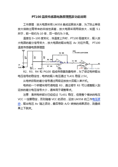
工作原理:放大电路采用LM358 集成运算放大器,为了防止单级放大倍数过高带来的非线性误差,放大电路采用两级放大,如图5.1 所示,前一级约为10 倍,后一级约为3倍。
温度在0~100 度变化,当温度上升时,PT100 阻值变大,输入放大电路的差分信号变大,放大电路的输出电压Av 对应升高。
PT100温度传感器电路原理图
R2、R3、R4 和Pt100 组成传感器测量电桥,为了保证电桥输出电压信号的稳定性,电桥的输入电压通过TL431 稳至2.5V。
从电桥获取的差分信号通过两级运放放大后输入单片机。
电桥的一个桥臂采用可调电阻R3,通过调节R3 可以调整输入到运放的差分电压信号大小,通常用于调整零点。
注意:虽然电桥部分已经经过TL431 稳压,但是整个模块的电压VCC 一定要稳定,否则随着VCC 的波动,运放LM358 的工作电压波动,输出电压Av 随之波动,最后导致A/D 转换的结果波动,测量结果上下跳变。
任务一结合PT100电路学运放PT100实际上就是一个电阻,只不过该电阻比较特殊,电阻的阻值随着温度变化而变化(详见PT100分度表)。
要测量温度,只要能计算出PT100的电阻值,就可以通过PT100分度表找到相对应的温度。
常用的PT100根据接线方式不同分为2线式和3线式。
根据驱动方式不同,分为恒压驱动和恒流驱动。
在本节当中,我们通过讨论的方式来探索PT100的测温电路。
由于PT100测温电路涉及到运放的一些电路,在本节中我们的另外一个任务就是通过这些电路来加强对运放的理解,从应用电路中去学运放,要比教科书里单纯概念化的东西更有效。
如果PT100远距离测温,PT100远离采集器,PT100引线上的电阻不可忽略,所以在设计PT100的采集电路时,要分短距离测温和长距离测温。
我们先来分析一下短距离测温电路(不考虑引线电阻,两线PT100即可)。
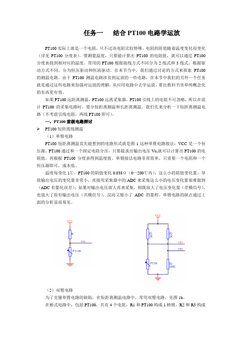
一、PT100前级电路探讨PT100短距离线测温(1)单臂电路PT100短距离测温首先能想到的电路形式就是图1这种单臂电路接法:VCC 是一个恒压源,PT100通过和一个固定电阻分压,只要能求出输出电压V O ,就可以计算出PT100的电阻值,再根据PT100分度表得到温度值。
单臂接法电路非常简单,只需要一个电阻和一个恒压源即可,成本低。
温度每变化1℃,PT100的阻值变化0.038Ω(0—200℃内),这么小的阻值变化量,导致输出电压的变化量非常小,直接用采集器中的ADC 来采集这么小的电压变化量很难做到(ADC 有量化误差);如果对输出电压放大再来采集,则既放大了电压变化量(差模信号),也放大了原有输出电压(共模信号),反而又缩小了ADC 的量程。
单臂电路的缺点通过上面的分析显而易见。
(2)双臂电路为了克服单臂电路的缺陷,在短距离测温电路中,常用双臂电路,见图1b 。
在桥式电路中,包括PT100,共有4个电阻,R1和PT100构成1桥臂,R2和R3构成1桥臂。

PT100三线制测量电路引言PT100 是一种广泛应用的测温元件,在-50℃~600℃范围内具有其他任何温度传感器无可比拟的优势,包括高精度、稳定性好、抗干扰能力强等。
由于铂热电阻的电阻值与温度成非线性关系,所以本模块需要进行非线性校正,一般的模块采用模拟电路校正,这种校正的精度不高,而且温漂等受干扰的程度也比较大。
本模块采用了软件查表插值的方法进行校正,最后转换成III型信号。
III型信号是当被测信号从下量程到上量程(0%~100%)变化时,输出线上对应4-20mA 电流的变化。
此外模块还具有MODBUS协议的通讯端口,可以直接和任何MODBUS口连接。
系统设计整个模块基于AVR新型的Atmega16单片机,采用三线制形式,这样可以去除导线电阻带来的零点不准确,经过差分放大电路直接得到0~5V的信号电压,这样就可以直接输入到A/D转换器。
数据处理部分,将PT100分度表中的每隔10℃的电阻值写入到闪存中,这样,将得到页脚内容1电压值回算到电阻值,这样进行查表,当电阻位于某一段之间时,再进行线性处理,这样系统的线性化程度比较高可以达到0.2%。
D/A转换系统采用373芯片作为锁存器,采用权电阻网络进行D/A转换,这样可以节省成本,而且精度也可以得到保证。
最后再经过一个电压电流转换部分,把信号以III型信号传送出去,完成模块的功能。
图1 采样电路采样电路采样电路如图1所示,PT100以三线制接到J0,这样连接PT100的两侧的导线长度相等,而且分别加在两侧的桥臂上,这样导线电阻得以消除,当 PT100输出100Ω时可以调节R1的阻值,以调整温度下限,当温度范围是0~300℃时,电桥电压经过放大后,Anolog0的电压正好是0~5V, 这样可以完整使用单片机的A/D转换器的转换精度。
页脚内容2图2 主机电路主机电路如图2。
CPU采用Atmega16 ,它自带8路10位A/D转换器,转换速度快,精度高,而且不需要外扩任何器件。
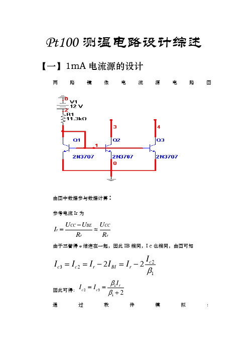
Pt100测温电路设计综述【一】1mA 电流源的设计两路镜像电流源电路图由图中数据参与数据计算:参考电流Ir 为CC BE CC r r r U U U I R R -=≈由于三管得e 结连在一起,因此IB 相同,I c 也相同,由图可知232122c c c r BI r I I I I I I β==-=-因此可得:12312rc c I I I ββ==+通过软件模拟:所需元器件小结:1.1:三极管2N3707,三只1.2:电阻11.3千欧1.3:电源12伏【二】仪用放大器的设计仪用放大器电路如下图所示:现所设计的仪用放大器是三运放结构,如上图。
它是由运放U1,U2按通向输入接法组成第一级查分放大电路,运放U3组成第二级差分放大电路。
在第一级电路中,Vi1,Vi2分别加到A1和A2的同向端,Rg和R5、R6组成的反馈网络,引入了负反馈。
由A1、A2虚短可得Vi1=V2;Vi2=V3; 1又由A1、A2虚断可得2又由A3虚断可得;整理得 3;整理得 4由A3虚短可得V5=V6; 5则由3.3式、3.4式和3.5式可得整理后可得6在上式中,如果我们选取电阻满足的关系,则输出电压可化简为7根据式3.2和3.7我们可以得到8通过软件模拟该部分所使用元器件小结:电源0.1伏电阻10千欧3个、45千欧2个、50千欧、100千欧电容30pF1个、100pF2个放大器LM108AD 2个LM108J8/883 1个【三】反相加法器设计反相加法器电路设计图如下:5V 校正-5v 输入使用反相比例放大器构成反相相加器。
因为运放开环增益很大,且引入并联电压负反馈。
11111i i u u u i R R ∑-==122222i i u u u i R R ∑-==2又因为是理想运算放大器,'0i i i -==,即运放输入端不索取电流,所以反馈电流f i 为12f i i i =+ 301212f f f f i i R R u i R u u R R =-=--4若12R R R==,则012()f i i R u u u R=-+ 5可见,实现了信号相加的功能,这种相加器的优点是利用了运放的虚地特性,使各信号源之间互不影响。
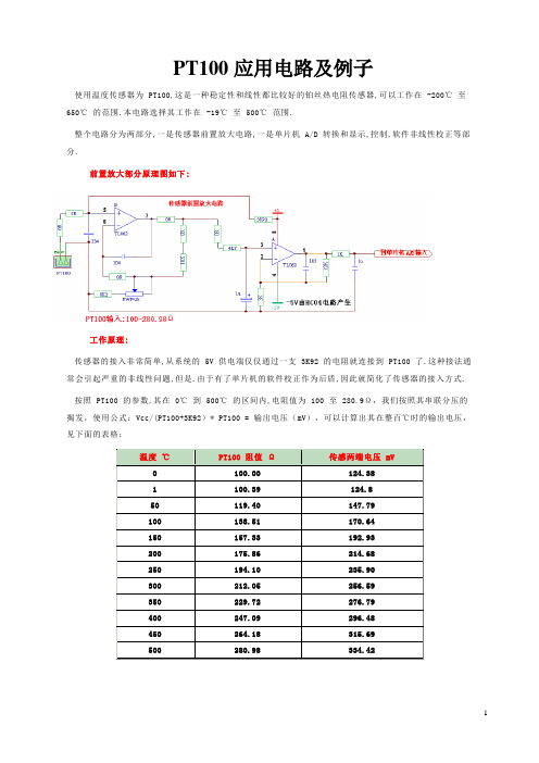
PT100应用电路及例子使用温度传感器为 PT100,这是一种稳定性和线性都比较好的铂丝热电阻传感器,可以工作在 -200℃至650℃的范围.本电路选择其工作在 -19℃至 500℃范围.整个电路分为两部分,一是传感器前置放大电路,一是单片机 A/D 转换和显示,控制,软件非线性校正等部分.前置放大部分原理图如下:工作原理:传感器的接入非常简单,从系统的 5V 供电端仅仅通过一支 3K92 的电阻就连接到 PT100 了.这种接法通常会引起严重的非线性问题,但是.由于有了单片机的软件校正作为后盾,因此就简化了传感器的接入方式. 按照 PT100 的参数,其在 0℃到 500℃的区间内,电阻值为 100 至 280.9Ω,我们按照其串联分压的揭发,使用公式:Vcc/(PT100+3K92)* PT100 = 输出电压(mV),可以计算出其在整百℃时的输出电压,见下面的表格:单片机的 10 位 A/D 在满度量程下,最大显示为 1023 字,为了得到 PT100 传感器输出电压在显示 500 字时的单片机 A/D 转换输入电压,必须对传感器的原始输出电压进行放大,计算公式为:(500/1023 * Vcc)/传感器两端电压( mV/℃ ) ,(Vcc=系统供电=5V),可以得到放大倍数为 10.466 。
关于放大倍数的说明:有热心的用户朋友询问,按照 (500/1023 * Vcc)/传感器两端电压不能得到 10.466 的结果,而是得到 11.635的结果。
实际上,500 个字的理想值是无法靠电路本身自然得到的,自然得到的数字仅仅为 450 个字,因此,公式中的 500℃在实际计算时的取值是 450 而不是 500 。
450/1023*5/(0.33442-0.12438)≈10.47 。
其实,计算的方法有多种,关键是要按照传感器的 mV/℃为依据而不是以被测温度值为依据,我们看看加上非线性校正系数:10.47*1.1117=11.639499 ,这样,热心朋友的计算结果就吻合了。
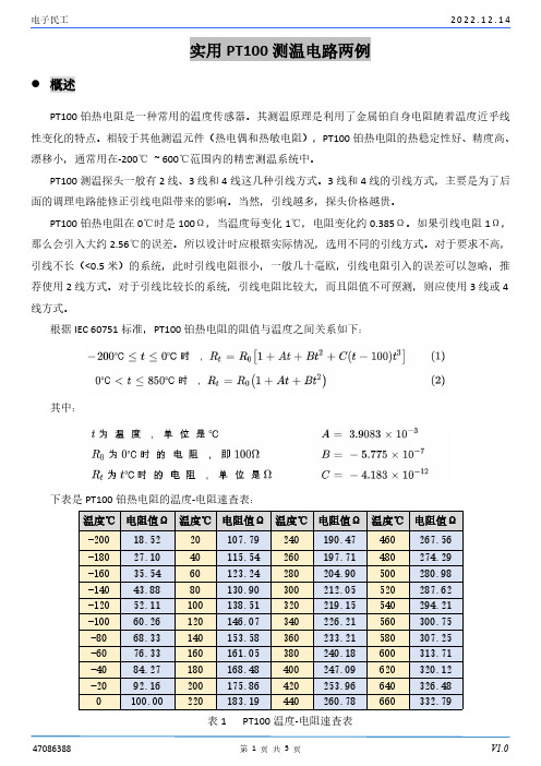
实用PT100测温电路两例概述PT100铂热电阻是一种常用的温度传感器。
其测温原理是利用了金属铂自身电阻随着温度近乎线性变化的特点。
相较于其他测温元件(热电偶和热敏电阻),PT100铂热电阻的热稳定性好、精度高、漂移小,通常用在-200℃~600℃范围内的精密测温系统中。
PT100测温探头一般有2线、3线和4线这几种引线方式。
3线和4线的引线方式,主要是为了后面的调理电路能修正引线电阻带来的影响。
当然,引线越多,探头价格越贵。
PT100铂热电阻在0℃时是100Ω,当温度每变化1℃,电阻变化约0.385Ω。
如果引线电阻1Ω,那么会引入大约2.56℃的误差。
所以设计时应根据实际情况,选用不同的引线方式。
对于要求不高,引线不长(<0.5米)的系统,此时引线电阻很小,一般几十毫欧,引线电阻引入的误差可以忽略,推荐使用2线方式。
对于引线比较长的系统,引线电阻比较大,而且阻值不可预测,则应使用3线或4线方式。
根据IEC60751标准,PT100铂热电阻的阻值与温度之间关系如下:其中:下表是PT100铂热电阻的温度-电阻速查表:温度℃电阻值Ω温度℃电阻值Ω温度℃电阻值Ω温度℃电阻值Ω-20018.5220107.79240190.47460267.56-18027.1040115.54260197.71480274.29-16035.5460123.24280204.90500280.98-14043.8880130.90300212.05520287.62-12052.11100138.51320219.15540294.21-10060.26120146.07340226.21560300.75-8068.33140153.58360233.21580307.25-6076.33160161.05380240.18600313.71-4084.27180168.48400247.09620320.12-2092.16200175.86420253.96640326.480100.00220183.19440260.78660332.79表1PT100温度-电阻速查表PT100铂热电阻温度采集系统主要有两种实现方式:1.恒流方式,2.电桥方式。

pt100测温电路设计方案
设计pt100测温电路的方案可以分为以下几个步骤:
1. 确定电源电压:首先确定电路的供电电压,一般情况下,
pt100测温电路常使用5V的电源供电。
2. 构建电桥电路:为了提高测温的精度,可以使用电桥电路来测量pt100的阻值变化。
电桥电路主要包括一个pt100传感器
和三个固定阻值的电阻。
电桥电路一般采用Wheatstone电桥。
3. 选择运放:为了放大pt100传感器的微小信号,一般使用运
放进行信号放大。
选择合适的运放需要考虑其增益、带宽、输入偏置电流等参数。
4. 温度转换:将pt100的阻值变化转换为温度值。
一般采用前
端运放进行小信号放大,后接一个模数转换器(ADC)将模
拟信号转换为数字信号,再通过数值计算将数字信号转换为实际温度值。
5. 界面显示:最后将测到的温度值通过显示器或者其他外设进行显示。
值得注意的是,设计pt100测温电路时需要考虑传感器的供电
方式、电路的抗干扰能力、运放的选择等因素,以保证测量的准确性和可靠性。
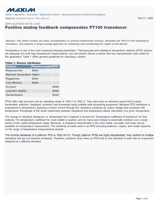
Maxim > App Notes > Automotive Measurement circuits Temperature sensors and thermal managementKeywords: temperature sensor, RTD, platinum Feb 21, 2005 APPLICATION NOTE 3450Positive analog feedback compensates PT100 transducerAbstract: This article reviews the basic characteristics of common temperature sensors, describes the RTD PT100 temperature transducer, and explains a simple analog approach for linearizing and conditioning the output of that device.Temperature is one of the most measured physical parameters. Thermocouple and resistance temperature detector (RTD) sensors are adequate for most high-temperature measurements, but one should choose a sensor that has characteristics best suited for the application. Table 1 offers general guidelines for choosing a sensor.Table 1. Sensor attributesThermocouple RTDResponse time BetterMaximum temperature HigherRuggedness BetterCost efficiency BetterAccuracy BetterLong-term stability BetterStandardization BetterRTDs offer high precision and an operating range of -200°C to +850°C. They also have an electrical output that is easily transmitted, switched, displayed, recorded, and processed using suitable data-processing equipment. Because RTD resistance is proportional to temperature, applying a known current through the resistance produces an output voltage that increases with temperature. Knowledge of the exact relationship between resistance and temperature allows calculation of a given temperature.The change in electrical resistance vs. temperature for a material is termed the "temperature coefficient of resistance" for that material. The temperature coefficient for most metals is positive, and for many pure metals is essentially constant over a large portion of the useful temperature range. Moreover, a resistance thermometer is the most stable, accurate, and linear device available for temperature measurement. The resistivity of metal used in an RTD (including platinum, copper, and nickel) depends on the range of temperature measurements desired.The nominal resistance of a platinum RTD is 100Ω at 0°C. Though platinum RTDs are highly standardized, they conform to multiple standards that are not identical worldwide. Therefore, problems arise when an RTD built to one standard is used with an instrument designed to a different standard.Table 2. Common standards for platinum RTDs*British Standard BS 1904:19840.003850100Deutschen Institut für Normung DIN 43760:19800.003850100International Electrotechnical Commission IEC 751:1995(Amend. 2)0.00385055100Scientific Apparatus Manufacturers of America SAMA RC-4-19660.00392398.129Japanese Standard JIS C1604-19810.003916100American Society forTesting and MaterialsASTM E11370.00385055100*Sensing Devices, Inc. manufactures platinum RTDs to these thermometry standards.Platinum's long-term stability, repeatability, fast response time, and wide temperature range make it a useful choice in many applications. As a result, platinum RTDs are recognized as the most reliable standard available for temperature measurement. The PT100 RTD is described by the following generic equation, which makes obvious a nonlinear relationship between temperature and resistance:R T = R0(1 + AT + BT² + C(T-100)T³)where:A = 3.9083 E-3B = -5.775 E-7C = -4.183 E-12 below 0°C, and zero above 0°CSee Table 3 for the corresponding data in tabular form.Table 3. Resistance/temperature table** for 385 platinum, 100.0Ω at 0°C 0123456789-10060.26-9064.363.8963.4963.0862.6862.2861.8761.4661.0660.66-8068.3267.9267.5267.1266.7266.3165.9165.5165.164.7-7072.3371.9371.5371.1370.7370.3369.9369.5369.1368.73-6076.3375.9375.5375.1374.7374.3373.9373.5373.1372.73-5080.3179.9179.5179.1278.7278.3277.9277.5277.1276.73 0123456789-4084.2783.8883.4883.0882.6982.2981.981.581.180.7-3088.2287.8387.4387.0486.6486.2585.8585.4685.0684.67-2092.1691.7791.3790.9890.5990.1989.889.489.0188.62-1096.0995.6995.394.9194.5294.1293.7393.3492.9592.55 010099.6199.2298.8398.4498.0497.6597.2696.8796.48 0123456789 0100100.39100.78101.17101.56101.95102.34102.73103.12103.51 10103.9104.29104.68105.07105.46105.85106.24106.63107.02107.4 20107.79108.18108.57108.96109.34109.73110.12110.51110.9111.28 30111.67112.06112.45112.83113.22113.61113.99114.38114.77115.15 40115.54115.92116.31116.7117.08117.47117.85118.24118.62119.01 012345678950119.4119.78120.16120.55120.93121.32121.7122.09122.47122.86 60123.24123.62124.01124.39124.77125.16125.54125.92126.31126.69 70127.07127.45127.84128.22128.6128.98129.36129.75130.13130.51 80130.89131.27131.66132.04132.42132.8133.18133.56133.94134.32 90134.7135.08135.46135.84136.22136.6136.98137.36137.74138.12 0123456789 100138.5138.88139.26139.64140.02140.4140.77141.15141.53141.91 110142.29142.66143.04143.42143.8144.18144.55144.93145.31145.68 120146.06146.44146.82147.19147.57147.94148.32148.7149.07149.44 130149.82150.2150.70150.95151.33151.7152.08152.45152.83153.2 140153.70153.95154.32154.7155.07155.45155.82156.2156.57156.94 0123456789 150157.32157.69170.06170.44170.81159.18159.56159.93160.3160.67 160161.04161.42161.79162.16162.53162.9163.28163.65164.02164.39 170164.76165.13165.5165.88166.24166.62166.99167.32167.73168.1 180168.47168.84169.21169.70169.95170.32170.68171.05171.42171.79 190172.16172.53172.9173.27173.64174174.37174.74175.11175.48 0123456789 200175.84**RTD PT100 table showing the relation between resistance and temperature.Figure 1. This two-wire connection affects measurement accuracy by adding resistance in series with the RTD.Figure 2. An additional third wire to the RTD allows compensation for the wire resistance. The only restriction is that the main connecting wires have the same characteristics.Figure 3. A four-wire approach enables Kelvin sensing, which eliminates the effect of voltage drops in the two connecting wires. You can connect a PT100 RTD to the measuring application using two wires, three wires, or four wires (Figures 1, 2, and 3). Several analog and digital approaches are available for compensating a PT100 RTD for nonlinearity. Digital linearization, for instance, can be implemented with a lookup table or by implementing the previous generic equation.A lookup table located in µP memory allows an application to convert (through interpolation) a measured PT100 resistance to the corresponding linearized temperature. On the other hand, the previous generic equation offers a possibility of calculating temperature values directly, based on the actual measured RTD resistance.A lookup table necessarily contains a limited number of resistance/temperature values, as dictated by the required accuracy and the amount of memory available. To calculate a specific temperature, you must first identify the two closest resistance values (those above and below the measured RTD value), and then interpolate between them.Consider a measured resistance of 109.73Ω, for example. If the lookup table has a resolution of 10°C, the two closest values might be 107.79Ω (20°C) and 111.67Ω (30°C). Interpolation using these three values leads to:This digital approach requires use of a microprocessor (µP), but the small circuit in Figure 4 performs accurate linearity compensation using the analog approach. It provides outputs of 0.97V at -100°C and 2.97V at 200°C. It may be necessary to add gain adjustment (span) and a level shift (offset) to cover an output range of -100mV at -100°C to 200mV at 200°C, for example.Figure 4. This analog circuit linearizes an RTD output.The suggested way to compensate for nonlinearity in the PT100 element is to apply a small amount of positive feedback throughR2. That feedback helps to linearize the transfer function by providing a slightly higher output at high PT100 values. The transfer function can easily be established by applying the superposition principle:Figure 5 shows the raw PT100 output vs. a linear approximation of the form y = ax + b, and Figure 6 shows a linearized version of the circuit output vs. the linear approximation. Each figure shows the calculated relationship between temperature and resistance compared to the output calculated from the Figure 4 circuit. The graphs of Figures 7 and 8 illustrate the PT100 error before and after analog compensation.Figure 5. Raw output of a normalized PT100 vs. a linear approximation to that output.Figure 6. Analog-compensated output vs. a linear approximation to that output, showing the error after linearization.Figure 7. Normalized error, representing the deviation between raw PT100 output, and a linear approximation of the PT100 relation between temperature and resistance.Figure 8. Normalized error, representing the deviation between the linearized output of Figure 4 and a linear approximation of the PT100 relation between temperature and resistance. Normalizing the curves of Figures 7 and 8 makes it easy to assess the performance of the Figure 4 circuit.When calibrating an analog thermometer, it is always preferable to minimize the need for adjustments and control measurements during production and calibration. Normally, it is best to adjust only the offset and span at two PT100 values. That approach, however, requires a linear relationship between PT100 resistance and temperature, which is not the case.The exercise above shows that analog compensation can reduce PT100 errors by a factor of approximately 80, assuming the transfer function exhibits a linear correlation between the PT100 value and the measured temperature. Additionally, low power dissipation in the PT100 (0.2mW to 0.6mW) minimizes self-heating. Thus, PT100 signals linearized using the analog approach allow an easy interface to ±200mV panel meters, for example, without additional software overhead.Figure 9. Digital approach: An ADC converts the RTD output to digital under control of a µP. Then, the µP calculates the corresponding temperature using a lookup table.An example of the digital approach (Figure 9) involves an RTD, a difference amplifier, a current source, and an ADC controlled by a µP (not shown). A temperature measurement is accomplished by driving a current of 1mA to 2mA through the sensor and measuring the resulting voltage drop across it. Higher currents cause higher power dissipation in the sensor, which in turn causes measurement errors due to self-heating. An internal 4.096V reference simplifies the generation of excitation current for the sensor.To prevent wire resistance from affecting measurement accuracy, four separate wires connect the RTD to the differential amplifier. Because the sense wires connect to the amplifier's high-impedance inputs, they have very low current and virtually no voltage drop. The 4096mV reference and 3.3kΩ feedback resistor sets the excitation current to approximately 4096mV/3.3kΩ = 1.24mA. Thus, driving the ADC and current source with the same reference voltage produces a ratiometric measurement in which reference drift does not influence the conversion result.By configuring the MAX197 for an input range of 0V to 5V and setting the differential amplifier for a gain of 10, you can measure resistance values up to 400Ω, which represents about +800°C. The µP can use a lookup table to linearize the sensor signal. To calibrate the system, replace the RTD with two precision resistors (100Ω for 0°C, and 300Ω or higher for full span) and store the conversion results.Related PartsMAX197Multi-Range (±10V, ±5V, +10V, +5V), Single +5V, 12-Bit DAS with 8+4 Bus Interface-- Free SamplesMAX4236SOT23, Very High Precision, 3V/5V Rail-to-Rail Op Amps-- Free SamplesMAX4237SOT23, Very High Precision, 3V/5V Rail-to-Rail Op Amps-- Free SamplesAutomatic UpdatesWould you like to be automatically notified when new application notes are published in your areas of interest? Sign up for EE-Mail™.Application note 3450: /an3450More informationFor technical support: /supportFor samples: /samplesOther questions and comments: /contact AN3450, AN 3450, APP3450, Appnote3450, Appnote 3450 Copyright © by Maxim Integrated ProductsAdditional legal notices: /legal。

基于mcp609设计的pt100运算放大电路MCp609 是一款双路运算放大器,具有高增益、宽频响、低噪声等优点。
基于MCp609 设计的PT100 运算放大电路主要用于处理和放大PT100 温度传感器输出的信号。
以下是基于MCp609 设计的PT100 运算放大电路的基本组成及工作原理:1. 电路组成:基于MCp609 的PT100 运算放大电路主要包括以下几个部分:- PT100 温度传感器:用于检测环境温度,并输出微弱的模拟信号。
- 放大器:采用MCp609 运算放大器,对PT100 传感器输出的信号进行放大。
- 滤波器:用于去除放大后的信号中的噪声,提高信号质量。
- 输出电路:将放大滤波后的信号传递给后续处理电路或负载。
2. 工作原理:PT100 温度传感器输出的信号非常微弱,需要经过放大器进行放大。
MCp609 运算放大器具有高增益,可以有效地将PT100 传感器输出的信号放大到合适的幅度。
同时,MCp609 具有宽频响特性,可以保证信号在放大过程中不损失过多的高频成分。
放大后的信号经过滤波器去除噪声,提高信号质量。
滤波器可以选择不同类型的滤波器,如低通、高通、带通等,以满足不同应用场景的需求。
最后,输出电路将滤波后的信号传递给后续处理电路或负载。
输出电路可以采用恒流源输出,以保证输出信号的稳定性。
3. 电路设计要点:在设计基于MCp609 的PT100 运算放大电路时,应注意以下几点:- 电源选择:为保证电路的稳定性和性能,应选择高质量的电源,如稳压电源或线性电源。
- 电阻选择:电路中涉及到的电阻应选择合适的数值,以保证放大器的增益和带宽。
- 滤波器设计:根据实际应用需求,设计合适的滤波器,以去除放大信号中的噪声。
- 输出电路设计:输出电路应具有足够的驱动能力,以满足不同负载的需求。
综上所述,基于MCp609 设计的PT100 运算放大电路可以有效地处理和放大PT100 温度传感器的输出信号,适用于各种温度测量应用。
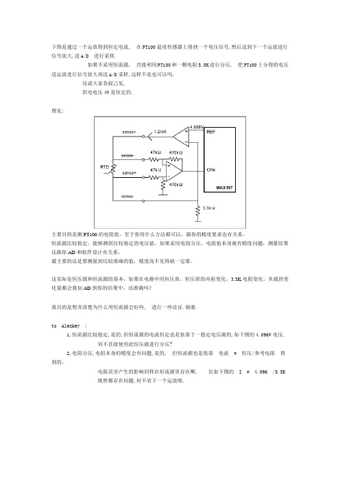
下图是通过一个运放得到恒定电流, 在PT100温度传感器上得到一个电压信号,然后送到下一个运放进行信号放大,送A/D 进行采样.如果不采用恒流源, 直接利用PT100和一颗电阻3.3K进行分压, 把PT100上分得的电压送运放进行信号放大再送A/D采样,这样不是也可以吗,还请大家各叙己见,供电电压4V是恒定的.图见:主要目的是测PT100的电阻值,至于你用什么方法都可以,跟你的精度要求也有关系。
恒流源比较稳定,能够测到比较稳定的电压值。
如果采用电阻分压,电阻值本身就有精度问题,测量结果还跟你AD和软件设计有关系,最主要的还是要测量到比较准确的值,精度高不见得就一定准。
这实际是恒压源和恒流源的基本,如果在电路中用恒压原,恒压原的内阻变化,3.3K电阻变化,负载的变化量都会叠加AD到你的结果中,还准确吗?我目的是想弄清楚为什么用恒流源会好些, 进行一些论证.谢谢.to Alexkey :1,恒流源比较稳定,是的,但恒流源的电流恒定也是依靠于一稳定电压源的,如下图的4.096V电压, 何不直接使用此恒压源进行分压?2,电阻分压,电阻本身的精度会有问题,是的, 但恒流源也是依靠电流 = 恒压/参考电阻得到的,电阻误差产生的影响同样在恒流源里存在啊, 比如下图的 I = 4.096 /3.3K既然都存在问题,何不省下一个运放呢.to suipeng70 :恒压源内阻变化, 如果采用PT100串一颗电阻分压采样的话,一般电流控制在2mA之内,恒压源内阻变化对这点电流的外接电路应该没什么影响的吧.至于3.3K参考电阻的变化会影响测量结果,但同样采用恒流源的方案里也存在这个问题的.单片机输出的4.096v参考是经过反馈调整的, 应该可以认为是恒定的,和负载的大小没有什么关系,当然负载不要太大了.我们先假定此参考电压恒定的条件下,是否采用电阻串联方式也是同样可以的,比如:4.096V直接给 2.2K电阻串联PT100 供电,在0度温度下,i=4.096/(2200+100)=1.74mA,PT100电压:v=4.096*(100/2200+100)=174mV把174mv的信号经过运放放大10倍,提供信号给单片机的A/D口采样,反推出PT100的电阻大小来查表计算温度.还是那句话,最首先要考虑温度传感器的电流恒定。
说明:
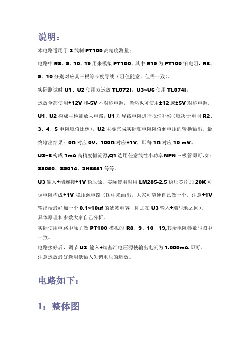
本电路适用于3线制PT100高精度测量;
电路中R8、9、10、19用来模拟PT100,其中R19为PT100铂电阻,R8、9、10分别对应其三根等长度导线(阻值随意,但需一致)。
实际测试时U1、U2使用双运放TL072I,U3~U6使用TL074I;
运放全部使用+12V和-5V不对称电源,当然也可使用±12或±5V对称电源。
U1、U2构成主检测放大电路,U1对导线电阻进行抵消补偿(取决于电阻R2、3、4、5电阻取值比例),U2主要完成实际铂电阻阻值到电压的转换输出。
最终输出结果:0Ω对应0V,100Ω对应+1V,即每1Ω对应10 mV。
U3~6构成1mA高精度恒流源,Q1选用任意线性小功率NPN三极管即可,如:S8050、S9014、2N5551等等。
U3输入+端连接+1V稳压源,实际使用时用LM285-2.5稳压芯片加20K可调电阻构成+1V稳压源电路(图中未画出,大家可随便自己做一个,注意+1V 输出端最好加一个0.1~10uf的滤波电容,即加在U3输入+端与地之间)。
具体原理和参数大家自己分析。
实际使用电路中除了做PT100模拟的R8、9、10、19,其余电阻参数与图中一致。
电路接好后,调节U3 输入+端基准电压源使输出电流为1.000mA即可。
注意运放最好选用低输入失调电压的运放。
电路如下:
1:整体图
2:局部A,U1及周围电路。
3:局部B,U2及周围电路。
4:局部C,1mA恒流源电路。

pt100测温电路(经典测温范围)pt100 测温电路(经典测温范围):温度传感器PT100,可以工作在-200 度到650 度的范围。
整个电路分为两部分,一是传感器前置放大电路,一是单片机AD 转换和显示控制软件非线性校正等部分。
传感器前置放大电路:后级单片机的电路原理图:PT100 计算公式PT100 计算公式热电阻是中低温区最常用的一种温度检测器,它主要特点就是测量精度高,性能稳定.下面的是在单片机程序中我自己使用计算公式: 一:相关资料中给出的公式: 1. 铂热电阻的温度特性.在0~850℃范围内Rt=R0(1+At+Bt2) 在-200~0℃范围内Rt=R0[1+At+Bt2+C(t-100)t3] 式中A,B,C 的系数各为:A=3.90802 乘以103℃-1 B=-5.802 乘以107℃-2 C=-4.27350 乘以1012℃-4 2. 铜热电阻的温度特性:在-50~150℃范围内Rt=R0[1+At+Bt2+Ct3] A=4.28899 乘以103℃1 B=-2.133 乘以107℃2 C=1.233 乘以109℃3 二,程序中我自己使用的计算公式: 2.温度测量技术(PT100): 当T 0 RT=Rt 当T 420 RT= Rt+ Rt2*2.15805393*10-6 当0T 420 RT= Rt*[1+(R420-Rt)*3.301723797*10-7]+ Rt2*2.15805393*10-6 相关系数及说明: RT 为对应与温度的线形值,其结果等效于显示温度值Rt 为实际测量的阻抗值,其值是已经减去100(电桥差放的参考值)的值对应的16 进制值: 3.301723797*10-7 = B142h * 237 2.15805393*10-6 = 90D3h * 234 R420 = (25390-10000)*2.517082601*128 = 4BA8F3h(4958451.35736192) 其中这里的结果都是已经乘100 的值,在显示的时候应该先处理. 三:温度测量技术(CU50): RT=Rt(1+at) RT 和Rt 分别为温度为T℃和0℃时候的阻抗值. a 为铜电阻的温度系数.一般取4.25 乘以103/℃~4.28乘以103/℃tips:感谢大家的阅读,本文由我司收集整编。
pt100 电路计算公式一、pt100电路简介pt100是一种常见的温度传感器,常用于测量工业过程中的温度变化。
pt100电路是将pt100温度传感器与电路连接起来,通过测量传感器的电阻值来确定温度变化。
二、pt100电路计算公式pt100电路的计算公式是根据温度与电阻值之间的线性关系得出的。
pt100传感器的电阻值随着温度的变化而变化,其电阻值与温度之间的关系可以用以下公式表示:Rt = R0 * (1 + A * T + B * T^2 + C * (T - 100) * T^3)其中,Rt为传感器的电阻值,R0为传感器在0℃时的电阻值,T为传感器的温度(单位为摄氏度),A、B、C为特定pt100传感器的系数。
三、pt100电路的应用pt100电路广泛应用于各种工业过程的温度测量中,如石油化工、电力、冶金等领域。
通过测量pt100传感器的电阻值,可以准确地获得温度变化的信息。
为了实现对pt100电路的测量和控制,通常需要配合使用温度变送器和温度控制器等设备。
温度变送器将pt100传感器的电阻值转换为标准的电信号输出,以便传输给温度控制器进行处理和控制。
在实际应用中,需要根据具体的pt100传感器的参数来计算电路的电阻值。
通过测量电路中的电阻值,再利用计算公式,即可得到对应的温度值。
四、pt100电路计算公式的注意事项在使用pt100电路计算公式时,需要注意以下几点:1. 确保使用的pt100传感器的系数与计算公式中的系数一致,以确保计算结果的准确性。
2. 在计算过程中,要注意温度的单位。
通常情况下,温度的单位为摄氏度。
3. 电路中的电阻值应在合理范围内,以确保测量结果的准确性。
如果电阻值过大或过小,可能会导致计算结果的误差。
4. 在实际应用中,还需考虑电路的线性误差和温度漂移等因素,以确保温度测量的精度和稳定性。
五、总结本文介绍了pt100电路的计算公式及其应用。
通过理解和应用计算公式,可以准确地测量和控制温度变化,满足工业过程中对温度的要求。
PT100电路设计的思考PT100电路设计的思考我在设计PT100电路时,采用三线制的PT100进行设计,主要采取以下两种参考电路进行设计(如下图一所示)对于该电路,参考的是来在网上所得电路,经过修改放大器放大倍数,经输出、单片机10位采样,并计算所得。
但经过实验后发现,当线电阻Rw1、Rw2、Rw3在0~10欧姆的范围变化时,计算所得误差可以达到十几摄氏度,可以说就是基本上没有消除线电阻,测量时发现放大器输入两端电压稍有不同尤其是在U101B的变化尤为明显,再对电路进行仿真后,可以看出每个放大器的两输入端电压值都不完全相同,同时我们还发现,在放大倍数很大,或是输入电压差较大时,该误差可以基本消除,但在放大倍数较小,且输入电压较小时,其放大倍数会严重的失真,从而导致了输出结果存在较大的误差。
我分析原因是假设在线电阻较小的时候,放大后产生的结果误差会较大;在线电阻变大或是PT100电阻变大时,产生的结果会更接近于理论值,即该误差不是固定的,他随输入电压及放大倍数的增大而减小,甚至可以被消除。
因此,没有一个较好的方法来消除这个误差。
因此,希望各位大侠帮我再分析分析,看看还有什么改进之处,可以消除该误差。
在上面所说的电路没办法消除误差的时候,同学向我推荐了一本国外翻译教材书名为《嵌入式系统中的模拟设计》作者是美国的Bonnie Baker。
书中介绍了一种如图二所示的电路,该电路前一部分是一个产生1mA恒流源的设计电路,接通PT100之后,获得的电压完全可以和PT100的阻值呈线性变化。
然后,将PT100的A端和B 端接入放大器U3C中,按照理论设计,可以完全的消除线电阻,输出仅为PT100(Rx)两端的电压值,然后再经过U3D进行放大和二次滤波后输出。
这样的电路可以说设计的相当完美,考虑了消除线电阻和外界干扰所造成的影响,设计结果应当是正确合理的。
但实际上,在我对该电路进行仿真的时候,去发现和上面相同的问题,就是经U3C后,输出的电压很高(比PT100电阻两端的电压高很多,大概多3~6mV)。
Maxim > App Notes > Automotive Measurement circuits Temperature sensors and thermal management Keywords: temperature sensor, RTD, platinumFeb 21,2005APPLICATION NOTE 3450Positive analog feedback compensates PT100 transducerAbstract: This article reviews the basic characteristics of common temperature sensors, describes the RTD PT100 temperaturetransducer, and explains a simple analog approach for linearizing and conditioning the output of that device.Temperature is one of the most measured physical parameters. Thermocouple and resistance temperature detector (RTD) sensorsare adequate for most high-temperature measurements, but one should choose a sensor that has characteristics best suited forthe application. Table 1 offers general guidelines for choosing a sensor.Table 1. Sensor attributesFeatureThermocoupleRTDResponse timeRuggednessCost efficiencyAccuracyLong-term stabilityStandardizationBetterBetterBetter BetterBetterBetterMaximum temperatureHigher RTDs offer high precision and an operating range of -200°C to +850°C. They also have an electrical output that is easilytransmitted, switched, displayed, recorded, and processed using suitable data-processing equipment. Because RTD resistance isproportional to temperature, applying a known current through the resistance produces an output voltage that increases with temperature. Knowledge of the exact relationship between resistance and temperature allows calculation of a given temperature.The change in electrical resistance vs. temperature for a material is termed the "temperature coefficient of resistance" for thatmaterial. The temperature coefficient for most metals is positive, and for many pure metals is essentially constant over a largeportion of the useful temperature range. Moreover, a resistance thermometer is the most stable, accurate, and linear device available for temperature measurement. The resistivity of metal used in an RTD (including platinum, copper, and nickel) dependson the range of temperature measurements desired.The nomin al resistance of a platinum RTD is 100Ω at 0°C. Though platinum RTDs are highly standardized, they conform to multiplestandards that are not identical worldwide. Therefore, problems arise when an RTD built to one standard is used with an instrumentdesigned to a different standard.Page 1 of 9Table 2. Common standards for platinum RTDs*OrganizationBritish StandardDeutschen Institut fürNormungInternationalElectrotechnicalCommissionScientific ApparatusManufacturers ofAmericaJapanese StandardAmerican Society forTesting and MaterialsStandardBS 1904:1984DIN 43760:1980IEC 751:1995(Amend. 2)NominalALPHA (α): Average temperatureresistance atcoefficient of resistance (/°C)0°C (Ω)0.0038500.0038500.00385055100100100SAMA RC-4-0.0039231966JIS C1604-19810.00391698.129100100ASTM E11370.00385055*Sensing Devices, Inc. manufactures platinum RTDs to these thermometry standards. Platinum's long-term stability, repeatability, fast response time, and wide temperature range make it a useful choice in manyapplications. As a result, platinum RTDs are recognized as the most reliable standard available for temperature measurement. ThePT100 RTD is described by the following generic equation, which makes obvious a nonlinear relationship between temperature andresistance:RT = R0(1 + AT + BT² + C(T-100)T³)where:A = 3.9083 E-3B = -5.775 E-7C = -4.183 E-12 below 0°C, and zero above 0°CSee Table 3 for the corresponding data in tabular form.Page 2 of 9Table 3. Resistance/temperature table** for 385 platinum, 100.0Ω at 0°C°C0123456789 -10060.26-9064.364.763.8963.4963.0862.6862.2861.8761.4661.0660.66-8068.3267.9267.5267.1266.7266.3165.9165.5165.1-7072.3371.9371.5371.1370.7370.3369.9369.5369.1368.73-6076.3375.9375.5375.1374.7374.3373.9373.5373.1372.73-5080.3179.9179.5179.1278.7278.3277.9277.5277.1276.73°C0123456781.589.4881.1980.7-4084.2783.8883.4883.0882.6982.2981.9-2092.1691.7791.3790.9890.5990.1989.8-1096.0995.6995.3°C10203040°C5060708090°C100010012-3088.2287.8387.4387.0486.6486.2585.8585.4685.0684.6789.0188.6294.9194.5294.129 3.7393.3492.9592.55345678999.6199.2298.8398.4498.0497.6597.2696.8796.48100.39 100.78101.17101.56101.95102.34102.73103.12103.51103.9104.29104.68105.07105.46 105.85106.24106.63107.02107.4107.79108.18108.57108.96109.34109.73110.12110.51 110.9111.28111.67112.06112.45112.83113.22113.61113.99114.38114.77115.15115.54 115.92116.31116.7117.08117.47117.85118.24118.62119.010123456789119.4119.7812 0.16120.55120.93121.32121.7122.09122.47122.86123.24123.62124.01124.39124.7712 5.16125.54125.92126.31126.69127.07127.45127.84128.22128.6128.98129.36129.7513 0.13130.51130.89131.27131.66132.04132.42132.8133.18133.56133.94134.32134.7135 .08135.46135.84136.22136.6136.98137.36137.74138.120123456789100138.5138.88139.26139.64140.02140.4140.77141.15141.53141.91110142.29142.66 143.04143.42143.8144.18144.55144.93145.31145.68120146.06146.44146.82147.1914 7.57147.94148.32148.7149.07149.44130149.82150.2150.70150.95151.33151.7152.081 52.45152.83153.2140153.70153.95154.32154.7155.07155.45155.82156.2156.57156.94°C0123456789150157.32157.69170.06170.44170.81159.18159.56159.93160.3160.67160161.04161.4 2161.79162.16162.53162.9163.28163.65164.02164.39170164.76165.13165.5165.8816 6.24166.62166.99167.32167.73168.1180168.47168.84169.21169.70169.95170.32170.6 8171.05171.42171.79190172.16172.53172.9173.27173.64174°C012345174.37174.74175.11175.486789200175.84**RTD PT100 table showing the relation between resistance and temperature.Page 3 of 9Figure 1. This two-wire connection affects measurement accuracy by adding resistance in series with the RTD.Figure 2. An additional third wire to the RTD allows compensation for the wire resistance. The only restriction is that the mainconnecting wires have the same characteristics.Figure 3. A four-wire approach enables Kelvin sensing, which eliminates the effect of voltage drops in the two connecting wires.You can connect a PT100 RTD to the measuring application using two wires, three wires, or four wires (Figures 1, 2, and 3).Several analog and digital approaches are available for compensating a PT100 RTD for nonlinearity. Digital linearization, forinstance, can be implemented with a lookup table or by implementing the previous generic equation.Page 4 of 9A lookup table located in µP memory allows an application to convert (through interpolation) a measured PT100 resistance to thecorresponding linearized temperature. On the other hand, the previous generic equation offers a possibility of calculating temperature values directly, based on the actual measured RTD resistance.A lookup table necessarily contains a limited number of resistance/temperature values, as dictated by the required accuracy andthe amount of memory available. To calculate a specific temperature, you must first identify the two closest resistance values(those above and below the measured RTD value), and then interpolate between them. Consider a measured resistance of 109.73Ω, for example. If the lookup table has a resolution of 10°C, the two closest values mightbe 107.79Ω (20°C) and 111.67Ω (30°C). Interpolation using these three values leads to: This digital approach requires use of a microprocessor (µP), but the small circuit in Figure 4 performs accurate linearitycompensation using the analog approach. It provides outputs of 0.97V at -100°C and 2.97V at 200°C. It may be necessary to addgain adjustment (span) and a level shift (offset) to cover an output range of -100mV at -100°C to 200mV at 200°C, for example.Figure 4. This analog circuit linearizes an RTD output.The suggested way to compensate for nonlinearity in the PT100 element is to apply a small amount of positive feedback throughR2. That feedback helps to linearize the transfer function by providing a slightly higher output at high PT100 values. The transferfunction can easily be established by applying the superposition principle: Page 5 of 9Figure 5 shows the raw PT100 output vs. a linear approximation of the form y = ax + b, and Figure 6 shows a linearized versionof the circuit output vs. the linear approximation. Each figure shows the calculated relationship between temperature and resistancecompared to the output calculated from the Figure 4 circuit. The graphs of Figures 7 and 8 illustrate the PT100 error before andafter analog compensation.Figure 5. Raw output of a normalized PT100 vs. a linear approximation to that output. Page 6 of 9Figure 6. Analog-compensated output vs. a linear approximation to that output, showing the error after linearization.Figure 7. Normalized error, representing the deviation between raw PT100 output, and a linear approximation of the PT100 relationbetween temperature and resistance.Figure 8. Normalized error, representing the deviation between the linearized output of Figure 4 and a linear approximation of thePT100 relation between temperature and resistance. Normalizing the curves of Figures 7 and 8 makes it easy to assess theperformance of the Figure 4 circuit.Page 7 of 9When calibrating an analog thermometer, it is always preferable to minimize the need for adjustments and control measurementsduring production and calibration. Normally, it is best to adjust only the offset and span at two PT100 values. That approach,however, requires a linear relationship between PT100 resistance and temperature, which is not the case.The exercise above shows that analog compensation can reduce PT100 errors by a factor of approximately 80, assuming thetransfer function exhibits a linear correlation between the PT100 value and the measured temperature. Additionally, low powerdissipation in the PT100 (0.2mW to 0.6mW) minimizes self-heating. Thus,PT100 signals linearized using the analog approachallow an easy interface to ±200mV panel meters, for example, without additional software overhead.Figure 9. Digital approach: An ADC converts the RTD output to digital under control of a µP. Then, the µP calculates thecorresponding temperature using a lookup table.An example of the digital approach (Figure 9) involves an RTD, a difference amplifier, a current source, and an ADC controlled bya µP (not shown). A temperature measurement is accomplished by driving a current of 1mA to 2mA through the sensor andmeasuring the resulting voltage drop across it. Higher currents cause higher power dissipation in the sensor, which in turn causesmeasurement errors due to self-heating. An internal 4.096V reference simplifies the generation of excitation current for the sensor.To prevent wire resistance from affecting measurement accuracy, four separate wires connect the RTD to the differential amplifier.Because the sense wires connect to the amplifier's high-impedance inputs, they have very low current and virtually no voltagedrop. The 4096mV reference and 3.3kΩ feedback resistor sets the excitation current to approximately 4096mV/3.3kΩ = 1.24mA.Thus, driving the ADC and current source with the same reference voltage produces a ratiometric measurement in which referencedrift does not influence the conversion result.By configuring the MAX197 for an input range of 0V to 5V and setting the d ifferential amplifier for a gain of 10, you can measureresistance values up to 400Ω, which represents about +800°C. The µP can use a lookup table to linearize the sensor signal. Tocalibrate the system, replace the RTD with two precision resistors (100Ω for 0°C, and 300Ω or higher for full span) and store theconversion results.Related PartsMAX197Multi-Range (±10V, ±5V, +10V, +5V), Single +5V, 12-Bit DAS with 8+4 Bus Interface-- Free SamplesMAX4236SOT23, Very High Precision, 3V/5V Rail-to-Rail Op AmpsMAX4237SOT23, Very High Precision, 3V/5V Rail-to-Rail Op Amps-- Free Samples-- Free SamplesAutomatic UpdatesWould you like to be automatically notified when new application notes are published in your areas of interest? Sign up for EE-Mail™.Application note 3450: /an3450More informationFor technical support: /supportFor samples: /samplesPage 8 of 9Other questions and comments: /contact AN3450, AN 3450,APP3450, Appnote3450, Appnote 3450Copyright © by Maxim Integrated Products Additional legal notices: /legalPage 9 of 9。
签:Pt100(1)运算放大器(1)运算放大器组成的电路五花八门,令人眼花瞭乱,是模拟电路中学习的重点。
在分析它的工作原理时倘没有抓住核心,往往令人头大。
为此本人特搜罗天下运放电路之应用,来个“庖丁解牛”,希望各位从事电路板维修的同行,看完后有所斩获。
遍观所有模拟电子技朮的书籍和课程,在介绍运算放大器电路的时候,无非是先给电路来个定性,比如这是一个同向放大器,然后去推导它的输出与输入的关系,然后得出Vo=(1+Rf)Vi,那是一个反向放大器,然后得出Vo=-Rf*Vi……最后学生往往得出这样一个印象:记住公式就可以了!如果我们将电路稍稍变换一下,他们就找不着北了!偶曾经面试过至少100个以上的大专以上学历的电子专业应聘者,结果能将我给出的运算放大器电路分析得一点不错的没有超过10个人!其它专业毕业的更是可想而知了。
今天,芯片级维修教各位战无不胜的两招,这两招在所有运放电路的教材里都写得明白,就是“虚短”和“虚断”,不过要把它运用得出神入化,就要有较深厚的功底了。
虚短和虚断的概念由于运放的电压放大倍数很大,一般通用型运算放大器的开环电压放大倍数都在80 dB 以上。
而运放的输出电压是有限的,一般在 10 V~14 V。
因此运放的差模输入电压不足1 mV,两输入端近似等电位,相当于“短路”。
开环电压放大倍数越大,两输入端的电位越接近相等。
“虚短”是指在分析运算放大器处于线性状态时,可把两输入端视为等电位,这一特性称为虚假短路,简称虚短。
显然不能将两输入端真正短路。
由于运放的差模输入电阻很大,一般通用型运算放大器的输入电阻都在1MΩ以上。
因此流入运放输入端的电流往往不足1uA,远小于输入端外电路的电流。
故通常可把运放的两输入端视为开路,且输入电阻越大,两输入端越接近开路。
“虚断”是指在分析运放处于线性状态时,可以把两输入端视为等效开路,这一特性称为虚假开路,简称虚断。
显然不能将两输入端真正断路。
在分析运放电路工作原理时,首先请各位暂时忘掉什么同向放大、反向放大,什么加法器、减法器,什么差动输入……暂时忘掉那些输入输出关系的公式……这些东东只会干扰你,让你更糊涂﹔也请各位暂时不要理会输入偏置电流、共模抑制比、失调电压等电路参数,这是设计者要考虑的事情。
我们理解的就是理想放大器(其实在维修中和大多数设计过程中,把实际放大器当做理想放大器来分析也不会有问题)。
好了,让我们抓过两把“板斧”------“虚短”和“虚断”,开始“庖丁解牛”了。
图一运放的同向端接地=0V,反向端和同向端虚短,所以也是0V,反向输入端输入电阻很高,虚断,几乎没有电流注入和流出,那么R1和R2相当于是串联的,流过一个串联电路中的每一只组件的电流是相同的,即流过R1的电流和流过R2的电流是相同的。
流过R1的电流I1 = (Vi - V-)/R1 ……a 流过R2的电流I2 = (V- - Vout)/R2 ……b V- = V+ = 0 ……c I1 = I2 ……d 求解上面的初中代数方程得Vout = (-R2/R1)*Vi 这就是传说中的反向放大器的输入输出关系式了。
图二中Vi与V-虚短,则 Vi = V- ……a 因为虚断,反向输入端没有电流输入输出,通过R1和R2 的电流相等,设此电流为I,由欧姆定律得: I = Vout/(R1+R2)……b Vi 等于R2上的分压,即:Vi = I*R2 ……c 由abc式得Vout=Vi*(R1+R2)/R2 这就是传说中的同向放大器的公式了。
图三中,由虚短知: V- = V+ = 0 ……a 由虚断及基尔霍夫定律知,通过R2与R1的电流之和等于通过R3的电流,故(V1 – V-)/R1 + (V2 – V-)/R2 = (Vout – V-)/R3 ……b 代入a式,b式变为V1/R1 + V2/R2 = Vout/R3 如果取R1=R2=R3,则上式变为Vout=V1+V2,这就是传说中的加法器了。
请看图四。
因为虚断,运放同向端没有电流流过,则流过R1和R2的电流相等,同理流过R4和R3的电流也相等。
故(V1 – V+)/R1 = (V+ - V2)/R2 ……a (Vout – V-)/R3 = V-/R4 ……b 由虚短知: V+ = V- ……c 如果R1=R2,R3=R4,则由以上式子可以推导出 V+ = (V1 + V2)/2 V- = Vout/2 故 Vout = V1 + V2 也是一个加法器,呵呵!图五由虚断知,通过R1的电流等于通过R2的电流,同理通过R4的电流等于R3的电流,故有(V2 – V+)/R1 = V+/R2 ……a (V1 – V-)/R4 = (V- - Vout)/R3 ……b 如果R1=R2,则V+ = V2/2 ……c 如果R3=R4,则V- = (Vout + V1)/2 ……d 由虚短知 V+ = V- ……e 所以 Vout=V2-V1 这就是传说中的减法器了。
图六电路中,由虚短知,反向输入端的电压与同向端相等,由虚断知,通过R1的电流与通过C1的电流相等。
通过R1的电流 i=V1/R1 通过C1的电流i=C*dUc/dt=-C*dVout/dt 所以 Vout=((-1/(R1*C1))∫V1dt 输出电压与输入电压对时间的积分成正比,这就是传说中的积分电路了。
若V1为恒定电压U,则上式变换为Vout = -U*t/(R1*C1) t 是时间,则Vout输出电压是一条从0至负电源电压按时间变化的直线。
图七中由虚断知,通过电容C1和电阻R2的电流是相等的,由虚短知,运放同向端与反向端电压是相等的。
则: Vout = -i * R2 = -(R2*C1)dV1/dt 这是一个微分电路。
如果V1是一个突然加入的直流电压,则输出Vout对应一个方向与V1相反的脉冲。
图八。
由虚短知 Vx = V1 ……a Vy = V2 ……b 由虚断知,运放输入端没有电流流过,则R1、R2、R3可视为串联,通过每一个电阻的电流是相同的,电流I=(Vx-Vy)/R2 ……c 则: Vo1-Vo2=I*(R1+R2+R3) = (Vx-Vy)(R1+R2+R3)/R2 ……d 由虚断知,流过R6与流过R7的电流相等,若R6=R7,则Vw = Vo2/2 ……e 同理若R4=R5,则Vout – Vu = Vu – Vo1,故Vu = (Vout+Vo1)/2 ……f 由虚短知,Vu = Vw ……g 由efg得 Vout = Vo2 – Vo1 ……h 由dh得 Vout = (Vy –Vx)(R1+R2+R3)/R2 上式中(R1+R2+R3)/R2是定值,此值确定了差值(Vy –Vx)的放大倍数。
这个电路就是传说中的差分放大电路了。
分析一个大家接触得较多的电路。
很多控制器接受来自各种检测仪表的0~20mA或4~20mA电流,电路将此电流转换成电压后再送ADC转换成数字信号,图九就是这样一个典型电路。
如图4~20mA电流流过采样100Ω电阻R1,在R1上会产生0.4~2V的电压差。
由虚断知,运放输入端没有电流流过,则流过R3和R5的电流相等,流过R2和R4的电流相等。
故:(V2-Vy)/R3 = Vy/R5 ……a (V1-Vx)/R2 = (Vx-Vout)/R4 ……b 由虚短知: Vx = Vy ……c 电流从0~20mA变化,则V1 = V2 + (0.4~2)……d 由cd式代入b式得(V2 + (0.4~2)-Vy)/R2 = (Vy-Vout)/R4 ……e 如果R3=R2,R4=R5,则由e-a得Vout = -(0.4~2)R4/R2 ……f 图九中R4/R2=22k/10k=2.2,则f式Vout = -(0.88~4.4)V,即是说,将4~20mA电流转换成了-0.88 ~ -4.4V电压,此电压可以送ADC去处理。
电流可以转换成电压,电压也可以转换成电流。
图十就是这样一个电路。
上图的负反馈没有通过电阻直接反馈,而是串联了三极管Q1的发射结,大家可不要以为是一个比较器就是了。
只要是放大电路,虚短虚断的规律仍然是符合的!由虚断知,运放输入端没有电流流过,则(Vi – V1)/R2 = (V1 – V4)/R6 ……a同理(V3 – V2)/R5 = V2/R4 ……b由虚短知 V1 = V2 ……c如果R2=R6,R4=R5,则由abc式得V3-V4=Vi上式说明R7两端的电压和输入电压Vi相等,则通过R7的电流I=Vi/R7,如果负载RL《《100KΩ,则通过Rl和通过R7的电流基本相同。
来一个复杂的,呵呵!图十一是一个三线制PT100前置放大电路。
PT100传感器引出三根材质、线径、长度完全相同的线,接法如图所示。
有2V的电压加在由R14、R20、R15、Z1、PT100及其线电阻组成的桥电路上。
Z1、Z2、Z3、D11、D12、D83及各电容在电路中起滤波和保护作用,静态分析时可不予理会,Z1、Z2、Z3可视为短路,D11、D12、D83及各电容可视为开路。
由电阻分压知, V3=2*R20/(R14+20)=200/1100=2/11 ……a 由虚短知,U8B第6、7脚电压和第5脚电压相等 V4=V3 ……b 由虚断知,U8A第2脚没有电流流过,则流过R18和R19上的电流相等。
(V2-V4)/R19=(V5-V2)/R18 ……c 由虚断知,U8A 第3脚没有电流流过, V1=V7 ……d 在桥电路中R15和Z1、PT100及线电阻串联,PT100与线电阻串联分得的电压通过电阻R17加至U8A的第3脚, V7=2*(Rx+2R0)/(R15+Rx+2R0)…。
.e 由虚短知,U8A第3脚和第2脚电压相等, V1=V2 ……f 由abcdef 得,(V5-V7)/100=(V7-V3)/2.2 化简得 V5=(102.2*V7-100V3)/2.2 即 V5=204.4(Rx+2R0)/(1000+Rx+2R0)– 200/11 ……g 上式输出电压V5是Rx的函数我们再看线电阻的影响。
Pt100最下端线电阻上产生的电压降经过中间的线电阻、Z2、R22,加至U8C的第10脚,由虚断知, V5=V8=V9=2*R0/(R15+Rx+2R0)……a (V6-V10)/R25=V10/R26 ……b 由虚短知, V10=V5 ……c 由式abc得 V6=(102.2/2.2)V5=204.4R0/[2.2(1000+Rx+2R0)]……h 由式gh组成的方程组知,如果测出V5、V6的值,就可算出Rx及R0,知道Rx,查pt100分度表就知道温度的大小了。