日本高田TAKADA双电源转换开关产品手册-简版01
- 格式:pdf
- 大小:15.95 MB
- 文档页数:12
SY5000/CMU-BATS Auto Switch controllerUser ManualV1.1CONTENTS1.FEATURES………………………………………………………………2.2.CONTROLLER EXTERIOR FIGURE………………………………………3.3.PARAMETER RANGE AND DEFINE………………………………………3.4.OPERATION………………………………………………………………4.4-1KEY FUNCTION4-2SETTING PARAMETER4-3MANUAL OPERATION4-4AUTOMATIC OPERATION5.FACTORY DEFAULTSPARAMETER……………………………………………………………5.6.INSTALLATION…………………………………………………………5.7.TYPICAL WIRING DIAGRAM……………………………………………6.8.SALE SERVICE…………………………………………………………7.1、FEATURESSY5000/CMU-B double power switching controller is based on micro processor as the core of the new generation of intelligent controller. Real-time monitoring the mains and backup power these two road voltage. Be able to appear lost electricity,over-voltage,undervoltage,phase lack,etc,abnormal conditions make accurate judgement.And by manual or automatic mode switch ATS switch movement,which realizes automatic and unattended function,etc.n The ATS controller be used LCD digital design,Parameters is Chinese and English display.n The product can accurately acquisition and display the main power/second power two way three-phase voltages.n The product parameter settings by password protection.n The ATS controller power supply mode can set mains power priority,backup power priority or no priority.n When a switch off failure,if another voltage to normal,the ATS controller will automatically switch to the way.n The ATS controller can install voltage alarm value and delay switch time.n The product have generator start function.n The ATS controller can chose single-phase/three-phase display,monitoring.n The product have two way N line separation design.n The ATS controller can autosave fault record,inquires is more conveniently.n The ATS controller can be used DC power(9~35V)supply or A/N phase voltage.2、CONTROLLER EXTERIOR FIGURESY5000CMU-B3、SPECIFICATIONS3.1Power Supply :DC12V (range from 9to 35V );AC220V (197-270V )L-N3.2Generator input Voltage Range :0to220V AC ,3phase 4wire 3.3Power dissipation :<3VA at rated voltage34Operating Temperature Range :-20℃to +60℃Humidity Range :20℃to 75℃4、OPERATION4-1、controller display properly state as follows:4-2、SETTINGPARAMETERPress the []key 5seconds,enter "password"interface,Input 4digit password,User can only by monitoring software to modify this password,Ordinary users password:1234Password input method:In the input password interface,Press the []key,value add 1,Whenvalues increase to password bits,Pressthekey confirmation,Then interface jump to the second password bits,Repeat the above operation,input the remaining three password bits,and then enter into "menu",if a password mistake will not have access to menu system.In the menu system,Press the[]key into the next page ,Press the[]key to modification parameter.When the control screen upwardmodification parameter.Then press []key to increase the value,Increased to maximum continuous buttons,then the system automatically return to low cycle.If press []key,then exit set condition returns to the system default state.4.3Manual switching operationWhen the user manual debugging ATS switch,Through panel of buttons can be manually switched,each time press the button will switch to correspond to the end.Specific steps:Press the[]key will be the key controller is set to "manual"state,If switch to the main source control please press the []key,If switch to standby power control please press the []key.Note:in key-press,controller has 6seconds countdown switch time,press other switch button is invalid,and if the countdown unfinished.0000User can also through input password,the system parameters interface to "manual","automatic"Settings4.4Automatic switching set operationwhen the movement User Settings ATS switch automatically,need through controller internal priority to set up"the mains priority"-"standby power priority"-"no priority".Specific steps:First press the[]key to enter the password Settings,enter the correctpassword and press the[]key to scroll to"power priority model"interface,After press[]key choose"mains first"or"standby power first"or"no priority"of three modes.If exit system press the[]key.5、FACTORY DEFAULTS PARAMETERTepy Factory Reset Set rangemains under voltage200V180V-220Vmains over voltage240V230V-250V200V180V-220VBackup power undervoltage240V230V-250VBackup power overvoltageMains time delay normal5S0-60S5S0-60SMains time delayabnormalBackup time delay5S0-60Snormal5S0-60SBackup time delayabnormalGenerator start time0S0-90Sdelay5S0-90SGenerator stop timedelayPrior supply mode mains power priority:mains power priority:backup power priority:not priorityStatus Auto:manual:autoSupply display mode Display three phase Displaysingle-phase/threephaseDisplay switch time6S1-9SRecover factory set Not recover:recover:not recover6、controller mountedcontroller mounted:With the product distribution two installation ears fixed.Overall dimension:140x120x56mm(W X H X D)Cut-out for fix dimension:128x112mm(W X H)7、connection diagram7-1、According to SY5000/CMU-B controller of each port after shell that correct connection wiring.SY5000/CMU-Bback diagram7-2、SY5000/CMU-B controller wiring terminal explainTerminal Wiring explain Remark A1、B1、C1、N1Connect mainsA,B,C,NAC198V-242VM1、M2Connect relay outputCLOSE1#16A250VACL1、L2Connect AC battlelineAC198V-242VVIN、GND connect DCplus-minus Controller power supply DC9V-36VM3、M4Connect relay outputCLOSE2#16A250VACA2、B2、C2、N2Connect backup powerA,B,C,NAC198V-242VM5、M6Connect generatorrelay output10A250VACAccording to SY5000/CMU-B controller of each port after shell that correct connection wiring.7-3、SY5000/CMU-B controller typical Wiring diagram(V1.0)8、Seventh,Post-sale serviceProvides the technical support,the product and the service for the customer,causes people's life and the work is simpler,is highly effective,is richly colorful,is our mission.the sztong outstanding electricity relies on the field leading high tech,the Informationization method, provides comprehensively,with heart and soul,the entire technical professional service to each kind of product customer,lets the customer momentarily enjoy from us omnipresent,the meticulous service concern.。
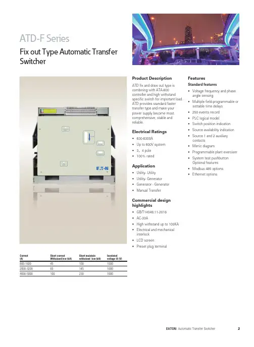
Product DescriptionATD fix and draw out type is combining with ATA-600 controller and high withstand specific switch for important load. ATD provides standard faster transfer type and make your power supply become most comprehensive, stable and reliable.Electrical Ratings• 630-6300A• Up to 600V system• 3,4 pole• 100% ratedApplication• Utility- Utility• Utility- Generator• Generator - Generator• Manual Transfer Commercial design highlights• GB/T14048.11-2016• AC-33A• High withstand up to 100KA• Electrical and mechanicalinterlock• LCD screen• Preset plug terminal FeaturesStandard features• Voltage frequency and phase angle sensing• Multiple field-programmable or settable time delays• 250 events record• PLC logical model• Switch position indication• Source availability indication• Source 1 and 2 auxiliarycontacts• Mimic diagram• Programmable plant exerciser• System test pushbuttonOptional features• Modbus 485 options• Ethernet optionsFix out Type Automatic TransferSwitcherCurrent (A)Short currentWithstand Icw (kA)Short maintainwithstand Icm (kA)Insulatedvoltage Ui (V)800-1600 2000-3200 4000-50004565100100145230100010001000Current (A)Short currentWithstand Icw (kA)Short maintain withstand Icm (kA)Insulated voltage Ui (V)800-16002000-32004000-50004565100100145230100010001000Draw out Type Automatic TransferSwitcherProduct DescriptionATD fix and draw out type is combining with ATA-600 controller and high withstandspecific switch for important load. ATD provides standard faster transfer type and make your power supply become most comprehensive, stable and reliable.Electrical Ratings• 630-6300A • Up to 600V system • 3,4 pole • 100% ratedApplication• Utility- Utility • Utility- Generator • Generator - Generator • Manual TransferCommercial design highlights• GB/T14048.11-2016• AC-33A• High withstand up to 100KA • Electrical and mechanical interlock • LCD screen • Preset plug terminalFeaturesStandard features• Voltage frequency and phase angle sensing • Multiple field-programmable or settable time delays • 250 events record • PLC logical model • Switch position indication • Source availability indication • Source 1 and 2 auxiliary contacts • Mimic diagram• Programmable plant exerciser • System test pushbutton Optional features • Modbus 485 options • Ethernet optionsATD8 SeriesDelay Type Automatic TransferSwitcherProduct DescriptionATD delay type is combining withATA-800 controller and highwithstand specific draw outswitch for important load. ATDdelay type provides a programma-ble delay time in transfer processwhich is required in transfer highrate generator and transformer.On the other hand, delay typetransfer are required in transferUPS or generator to reduce theimpact in the transfer process.Electrical Ratings• 630-6300A• Up to 600V system• 3,4 pole• 100% ratedApplication• Utility- Utility• Utility- Generator• Generator - Generator• Manual TransferCommercial designhighlights• GB/T14048.11-2016• AC-33A• High withstand up to 100KA• Electrical and mechanicalinterlock• LCD screen• Preset plug terminalFeaturesStandard features• Voltage frequency and phaseangle sensing• Multiple field-programmable orsettable time delays• 250 events record• PLC logical model• Switch position indication• Source availability indication• Source 1 and 2 auxiliarycontacts• Mimic diagram• Programmable plant exerciser• System test pushbuttonOptional features• Modbus 485 options• Ethernet optionsCurrent(A)Short currentWithstand Icw (kA)Short maintainwithstand Icm (kA)Insulatedvoltage Ui (V)800-16002000-32004000-50004565100100145230100010001000ATD SeriesFix Demission800-2000A Demission2500-3200A Demission535(4P)420(3P)473NormalEmergencyLocd4784-419.5(3P)(4P)t4-Fix holeFix holeFix holeFix holeFix holeNormalEmergencyLocdATD SeriesFix Demission4000-5000A Demission3P4PNormalEmergencyLocdATD SeriesDraw Demission800-2000A Demission2500-3200A Demission464(4P)349(3P)464(4P)349(3P)(4P)t349(3P)(4P)4-Fix holeFix hole Fix holeFix holeFix holeNormalEmergencyLocdNormalEmergencyLocdATD SeriesDraw Demission4000-6300A Demission3P4PNormalLocdEmergencyProduct guideATD SeriesDemission & Product guideController terminalsDemissionATA 610ATA610 ONLY。
HATS双电源自动转换开关电器使用说明书一.用途与特点1.1用途及适用范围HATS(HATSG隔离系列)双电源自动转换开关电器(以下简称自动切换装置),适用于交流50Hz,额定工作电压690V(400V)及以下,额定工作电流6A至1250A的双电源系统。
用以完成常用电源与备用电源的自动切换而无需人工操作,以达到无人值守之目的。
本产品符合IEC60947-6-1《自动转换开关电器》及国家标准GB/T14048.11-2002《低压开关设备和控制设备、自动转换开关电器》。
1.2产品特点☆体积小、结构简单、外形美观、操作方便、规格齐全;☆采用电机驱动,切换可靠平稳、无噪音,冲击力小;☆电机驱动只在开关切换瞬间有电流通过,稳态时无需提供工作电流,节能性好;☆有手动及自动两种工作模式,能带载自动切换,紧急时可采用手动切换;☆带有可靠的机械联锁和电气联锁装置,确保双电源工作互不干涉;☆有多种控制器,三极、四极装置均可提供,可满足不同用户需求。
二.产品性能和工作原理2. 1 HATS系列电源自动转换开关电气机械性能(见表1)表1 HATS系列电源自动转换开关电气机械性能表2. 2 HATSG系列电源自动转换开关技术性能指标(见表2)表2 HATSG系列电源自动转换开关技术性能指标表2.3产品工作原理N为常用电源,R为备用电源,Qn为常用电源控制断路器,Qr为备用电源控制断路器,两台断路器间有可靠的机械联锁和电气联锁双重保护。
控制器由电源监测、延时判断、操作控制3部分组成。
a)自动工作模式:如果常用电源正常时,控制器将备用电源断路器(Qr)断开,并在设定时间延迟后,将常用电源断路器(Qn)合上,由常用电源为下级负载供电。
当常用电源出现故障时,将正常供电断路器(Qn)断开,经过设定的时间延迟后,将备用电源断路器(Qr)合上,将下级负载从常用电源切换至备用电源。
当常用电源恢复正常时,将自动切换成常用电源供电。
b)手动工作模式:当控制开关置于手动工作模式时,用户可根据需要,使用操作手柄,进行常用电源与备用电源间的供电切换或将常用电源断路器(Qn)及备用电源断路器(Qr)同时置于分断状态,以进行下级电路的检修与维护。

GE双电源开关使用说明书V1.0广州宇象电气设备有限公司目录(一)目的方便第一次使用我司代理的GE的双电源开关产品,以GE的ZTG和其控制器MX150为例,作了简单的说明(二)GE双电源的组成1本体(ZTG)3CPS(控制电源)以ZTG为例,别的系列有所不同对于GTX相应的控制器为MX60(可选配MX90),对于ZTS相应的控制器为MX2504连接线(三)GE双电源的控制器MX150参数说明3.1控制器MX150的界面说明市电电源指示市电指示发电电源指示市电电源合闸指示市电指示发电机电源合闸指示2控制器(MX150)J5J5J6JC J7自检事件“即将出现”3.2MX150控制器的参数说明MX150的所有设置叁数:(常用参数设置见MX150参数设置)系统信息电源S1和S2的相电压电源S1和S2的频率SYSTEMINFO:系统信息Serial#:序列号Rev#:版本EventLog事件记录DATA统计记录CHANGEUSERACCESSCODE密码设定(原密码见控制器的背面)CONFIG(配置)TIMEREXERCISER(CDT单事件定时器自检程序-时间设定:1,7,14,28天,OFF.(DAILY(每天)、WEEKLY(每周)、14DAY(天)、28DAY(天)))TIMEREXERCISER(CDT单事件定时器自检程序-种类设定:XRF(有载)、NOXFR(无载)*CLOCKEXERCISER(CDP时钟自检程序:1,7,14,28天,OFF.(DAILY(每天)、WEEKLY(每周)、14DAY(天)、28DAY(天)、365DAY(天)))*TESTKEY(调试:Maintained/Momentary维护/瞬间)MOMENTARY(参数设置)TRANSFERCOMMIT(转换约定ON/OFF(开/关)。
ON:停电是接连不断的发生,如在停电延时内(还没有向S2电源转换),S1电源有电,转换开关动作;OFF:停电是一次孤立事件,如在停电延时内(还没有向S2电源转换),S1电源有电,转换开关不动作(开/关))INPHASEMONITOR(电源同步监测:ON/OFF(开/关):检查两路电源是否同步(频率是否在7个电度相位差))*PHASEIMBALANCE(VI)(3相电压不平衡监测:ON/OFF(开/关))*LOADDISCONNECTTD(UMD)(通用型电动机负载断开回路:辅助接点在以任何一个方向转换之前断开0-5分钟,转换之后,重新闭合)*NETWORK(通信功能:ON/OFF(开/关))SET(参数设置)SYSTEMCLOCK(系统时钟设定)DAYLIGHTSAVING(背光灯:ON/OFF(开/关))*CLOCKEXERCISER(CDP时钟自检程序:1,7,14,28天,OFF.(DAILY(每天)、WEEKLY(每周)、14DAY(天)、28DAY(天)、365DAY(天)))EXERS2RUNTIME(CDT单事件定时器自检程序-时间设定:1,7,14,28天,OFF.(DAILY(每天)、WEEKLY(每周)、14DAY(天)、28DAY(天)))S1UNDERVOLT(S1欠压门槛值)S2UNDERVOLT(S2欠压门槛值)S2UNDERFREQ(S2欠频门槛值)*PHASEIMBALANCE(VI)(3相电压不平衡监测-参数设定:FAIL5%,RESTORE3%)*PHASEIMBALANCE(VI)(3相电压不平衡监测-时间设定:TIMEDELAY30seconds)TIMEDELAYS2START(S2(发电机)启动延时(定义为定时器P):(0-10秒可调,标准整定3秒))TIMEDELAYS2STABLE(S2稳定延时(定义为定时器W):延时向电源2转换,时间可调范围0-5分钟)*LOADDPRDSIGNALTD(T3/W3)(电梯预信号辅助接点:在以任何一个方向转换之前断开0-60秒,转换之后,重新闭合) *LOADDISCONNECTTD(UMD)(通用型电动机负载断开回路:辅助接点在以任何一个方向转换之前断开0-5分钟,转换之后,重新闭合) ATSOPENTIMETOS2(S2延时转换(定义为定时器DW):从开关向电源2位置转换的时间延时(1-10分钟,标准设置为5秒))DW TIMEDELAYS1STABLE(电源S1稳定定时器(定义为定时器T):延时向电源1位置转换(电源2失灵情况下立即重新转换)时间可调范围0-60分钟,标准设置是30分钟ATSOPENTIMETOS1(S1延时转换(定义为定时器DT):从开关向电源1位置转换的时间延时(1-10分钟,标准设置为5秒))S2STOPDELQY(电源S2停止延时定时器(定义为定时器U):在开关重新转换至电源1以后允许发电机无载运行(1-60分钟,5分钟))CALIBRATES1(校正S1(电压,频率))CALIBRATES2(校正S2(电压,频率))TEST(调试)FASTTEST(快速调试)除发电机停机延时外所有定时器有效XFRLOAD(带负载调试)按键放后启动一次真实的转换操作。

Rated: voltage 220V 50/60HZNoted: power will be interrupted when Switching.Switch time<4SMax current: 63A.1. Dual power Automatic transfer switch can switch to Normal power or reserve power aut omatically. Please noted that the switch can’t turn on or turn off the generator. This switch Normal power first. If normal power on, the switch will switch to Normal power. If norma l power off, and reserve power on, the switch will switch to reserve power.2.WirePress the button to Automatic, the switch will switch to Normal power or reserve power au tomatically.Press the button to Manual, Then you have to switch the Direction manually.1.ApplicationTOQ3D is terminal type automatic transfer device. It’s suitable for 3 phases 4 wires (or 1 phase 1 wire) dual power grid with AC 50/60Hz, rated voltage 400V/230V and rated current up to 63A . When one power goes wrong (only test normal Phase A voltage and reserve Phase A voltage, o nly test loss voltage or loss phase),it will automatic connect one or several load circuits from one power to the other power automatically, to ensure normal power supply of load circuits.The automatic transfer switch conforms to IEC60947-6-1 and GB/T14048.112.Normal conditions for operation and installation:Environmental Temperature Condition:-5~+40°CInstallation site is not more than 2000 meters above sea level.Pollution Level: Grade 3Installation Category: 3Vertical installation or horizontal installation4. Main parameterRated Current Ie A 6,10,16,20,25,32,40 50, 63Electrical Appliances Class CBUse Category AC~33BTripping Current 5~10In (Type C), 10~15In (Type D), Rated voltage Ue 220V (2P),380V (3P or 4P)Rated frequency 50/60HzRated short circuit connecting ability Icm (Peak) 9.18KA 6.615KA Rated short circuit breaking ability Icn (effective value) 6KA 4.5KA6. Terminal wiring diagram7. Installation and wiringATSE can be installed in power control cabinet directly. Users can wire after ATSE installation (refer to design and use). As per current value use suitable conductor to connect the mains side (t op terminal) and load side (bottom terminal) of MCB of normal electric power and standby elect ric power. In-phase parallel connection at load side, and ensure the phase sequence of normal electric power a nd standby electric power must be accordant (Wire as per A,B,C,N sequence). For 3 poles ATS E should add one conductor with section not less than 0.3mm2 to connect theneuter line of pow er supply correctly, thus ATSE can work properly. For 4 poles or 2 poles ATSE, N pole of norm al electric power and standby electric power should be connected to N pole of MCB respectively . In addition, when install ATSE please ground reliably at grounding mark.8. Use1) Normal use, please set the switch of controller at Automatic Function. Under Auto working the controller of ATSE monitor normal electric power and standby electric power and display runn ing status of ATSE. When Normal power cut, novoltage, failure, ATSE will transfer load autom atically from normal power to standby power. If normal power get right, ATSE will transfer loa d automatically from standby power to normal power. The luminous diode on switch panel indic ate switch off situation.2) If you don’t adopt automatic transfer or need other manual operation please set the controlle r at manual. Under manual operation the controller stop work, and manual operation can make t he breaker on off, and the switch doesn’t transfer automatically.3) When ATSE is short circuit or over load, The MCB of ATSE will protect tripping. If power display normally the handle of MCB is switching on. If the MCB has protected tripping users sh ould set at manual and operate the switch to dual separating brake by hand, and check the reaso n of trip. After trouble clearing please set the controller at auto again to operate.4) When ATSE transfer to auto from manual, if normal and standby power are normal ATSE w ill prior connect normal power to load (even if load connected standby power ago)9. Matters need attentionWhen users test or operate please follow relative rules and pay attention to the following matter s to ensure use our ATES correctly.1)Neutral conductor N can’t be connected in wrong way, must connect reliably, otherwise ATSE can’t operate properly, even burn controller and motor.2)The protective grounding of ATSE must be connected reliably to ensure safety.3)Detection sampling signal for controller work power and main power supply is taken from Po wer supply side of main circuit, and work power of auxiliary connection terminal used for conne ct indicator is taken from main circuit, so can’t have voltage test between spare terminals (unless dismantle the secondary wires). Can have power frequency voltage test between main circuit and shell or between secondary auxiliary terminals and shell.10. Simple troubleshootingWhen users find fault can request professional to test and deal with. Keep Away for Safety whe n operate. Or contact our Specialized Service Departments.1) Double Power are both switched on, but ATSE can’t transfer automatically1 Check Auto/manual should be in automatic position.2 Check if incoming line is correct or not, if phase sequence is accordance or not, and wiring is s olid and reliable or not.3 Check if the fuse is burned on not.2) Double power are both switched on, ATSE standby power is switching on.4 Check if normal power incoming line has voltage or not.5 Check Commonly used insurance6 Check if external light is connected in wrong way or not。
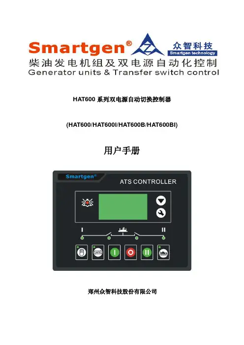
HAT600系列双电源自动切换控制器(HAT600/HAT600I/HAT600B/HAT600BI)用户手册郑州众智科技股份有限公司目录1概述 (3)2性能和特点 (3)3规格 (4)4操作 (5)4.1操作面板 (5)4.2按键功能描述 (5)5LCD显示 (6)5.1主界面 (6)5.2主菜单界面 (7)6试机操作 (7)7参数配置 (8)7.1参数配置表 (8)7.2输入/输出口功能描述 (11)8定时试机 (12)9日期时间设置 (13)10控制器信息 (13)11ATS操作运行 (13)11.1手动操作运行 (13)11.2自动操作运行 (13)11.3ATS供电电源 (13)12通信配置及连接 (14)13输入输出接口图 (15)14典型应用图 (16)15安装尺寸 (20)16故障排除 (20)1 概述HAT600系列双路电源自动切换控制器一种具有可编程功能、自动化测量、LCD显示,数字通讯为一体的智能化双电源切换模块。
它集数字化、智能化、网络化于一身,测量及控制过程实现自动化,减少人为操作失误,是双电源切换的理想产品。
HAT600系列双路电源自动切换控制器由微处理器为核心构成,可精确地检测两路三相电压,对出现的电压异常(过压、欠压、缺相、过频、欠频)做出准确的判断并输出无源控制开关量。
该装置充分考虑了在多种ATS(负载自动转换系统)上的应用,可直接用于专用ATS开关、接触器组成的ATS、空气开关组成的ATS等。
其结构紧凑、电路先进、接线简单、可靠性高,可广泛应用于电力、邮电、石油、煤炭、冶金、铁道、市政、智能大厦等行业、部门的电气装置、自动控制以及调试系统。
2 性能和特点★系统类型可设置为1#市电2#市电、1#市电2#发电、1#发电2#市电、1#发电2#发电;★LCD为128x64,带背光,两种语言(简体中文、英文)显示,轻触按钮操作;★采集并显示两路三相电压、频率参数;一路二路线电压Uab,Ubc,Uca 线电压Uab,Ubc,Uca相电压Ua,Ub,Uc 相电压Ua,Ub,Uc频率F1 频率F2★具有过压、欠压、缺相、逆相序、过频、欠频功能;★设有自动/手动状态切换,在手动方式下,可强制开关合分闸;★所有参数现场可编程,采用二级口令,防止非专业人员误操作;★现场可设定为带载/不带载模式进行发电机组的试机操作;★具有开关重合闸及断电再扣功能;★合闸输出可设为脉冲或持续输出;★可适用于一个分断位、两个分断位和无分段位开关;★两路N线分离设计;★实时时钟显示;★具有定时开停发电机组功能,可设定单次运行、每月一次或者每周一次,且均可设定是否带载运行。
ZJ-ATSDCWhen you learn more, you will be more determined to choose knowledge into electricalShanghai zhijin electric technology co., LTD. Has focused on the double power supply switch (ATS) research and development, sales and service. The earliest engaged in research and development of dc double power switching device to solve the dual dc, ac/dc and seamless switching technical prob-lems, from the fi rst generation of products to the third generation of products(ZJ-ATSDC), security and stability is applied to the dc system, greatly improve the power supply reliability, cost savings for the enterprise, to create e ffi ciency. Knowledge in science and technology with the rich experience in industry application and product line, for China and the world users improve the optimal electrical solutions.Company pro fi le1.Di ff erent voltage grade meet any customer needs, meet any dc switching fi elds, such as power plants, chemical industry, metallurgy, bank, data center, building, military industry, etc., is committed to intelligent product, com-pact, reliable and customized service solutions.Product introduceTypeA(mm)B(mm)ZJ-ATS DC220/110/48-10ZJ-ATS DC220/110/48-30ZJ-ATS DC220/110/48-50ZJ-ATS DC220/110/48-20ZJ-ATS DC220/110/48-40BC450450450450450135135135135135Operating instructionA(mm)B(mm)C(mm)D(mm)H(kg)ZJ-ATS DC220/110/48-60ZJ-ATS DC220/110/48-150ZJ-ATS DC220/110/48-400ZJ-ATS ZJ-ATS DC220/110/48-100ZJ-ATS DC220/110/48-250--450450450450450480480480480480 4.88101224135180200300350310310310310310MaintenancePerformance9.10.-3Customers11.12.Innovation Develop Value。
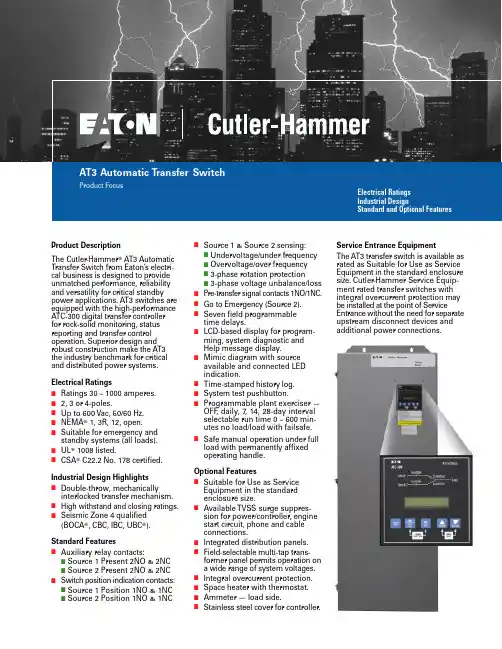
Product DescriptionThe Cutler -Hammer ா AT3 Automatic Transfer Switch from Eaton’s electri-cal business is designed to provide unmatched performance, reliability and versatility for critical standby power applications. AT3 switches are equipped with the high-performance ATC-300 digital transfer controller for rock-solid monitoring, status reporting and transfer control operation. Superior design and robust construction make the AT3the industry benchmark for critical and distributed power systems.Electrical RatingsI Ratings 30 – 1000 amperes.I 2, 3 or 4-poles.I Up to 600 Vac, 50/60 Hz.I NEMA ா 1, 3R, 12, open.I Suitable for emergency and standby systems (all loads).I UL ா 1008 listed.ICSA ா C22.2 No. 178 certified.Industrial Design HighlightsI Double-throw, mechanicallyinterlocked transfer mechanism.I High withstand and closing ratings.ISeismic Zone 4 qualified (BOCA ா, CBC, IBC, UBC ா).Standard FeaturesIAuxiliary relay contacts:I Source 1 Present 2NO & 2NC I Source 2 Present 2NO & 2NC ISwitch position indication contacts:I Source 1 Position 1NO & 1NC I Source 2 Position 1NO & 1NCISource 1 & Source 2 sensing:I Undervoltage/under frequency I Overvoltage/over frequency I 3-phase rotation protectionI 3-phase voltage unbalance/loss I Pre-transfer signal contacts 1NO/1NC.I Go to Emergency (Source 2).I Seven field programmable time delays.ILCD-based display for program-ming, system diagnostic and Help message display.IMimic diagram with source available and connected LED indication.I Time-stamped history log.I System test pushbutton.IProgrammable plant exerciser —OFF , daily, 7, 14, 28-day interval selectable run time 0 – 600 min-utes no load/load with failsafe.ISafe manual operation under full load with permanently affixed operating handle.Optional FeaturesISuitable for Use as Service Equipment in the standard enclosure size.IAvailable TVSS surge suppres-sion for power/controller, engine start circuit, phone and cable connections.I Integrated distribution panels.IField-selectable multi-tap trans-former panel permits operation on a wide range of system voltages.I Integral overcurrent protection.I Space heater with thermostat.I Ammeter — load side.IStainless steel cover for controller.Service Entrance EquipmentThe AT3 transfer switch is available as rated as Suitable for Use as Service Equipment in the standard enclosure size. Cutler-Hammer Service Equip-ment rated transfer switches with integral overcurrent protection may be installed at the point of ServiceEntrance without the need for separate upstream disconnect devices and additional power connections.Eaton Electrical Inc.1000 Cherrington Parkway Moon Township, PA 15108United States tel: 1-800-525-2000©2005 Eaton Corporation All Rights Reserved Printed in USAPub. No. PA01602002E / Z2897April 2005CSA is a registered trademark of the Canadian Standards Association. Cutler -Hammer is a federally registered trademark of Eaton Corporation. NEMA is the registered trademark and service mark of the National Electrical Manufacturers Association. UL is a federally registered trademark of Underwriters Laboratories Inc. BOCA is a registered trademark of Building Officials and Code Administrators International, Inc. Uniform BuildingCode (UBC) is a trademark of the International Conference of Building Officials (ICBO).Table 1. UL 1008 Withstand and Close-On Ratings (kA)ᕃ240 Vac.Switch Rating Amperes UL 1008 3-Cycle “Any Breaker” Rating Rating When Used With Upstream Fuse240 Vac 480 Vac 600 Vac Maximum Fuse Rating Fuse Type 600 Vac30 – 100 150150 – 225 225100100100100656565 ᕃ6525252525 200 400 400 400J, T J, T J, T J, T 200200200200 300 400 600100100100656565252525 400 6001200J, T J, T J, T 200200200 800100065 655050252516001600L L200200Table 2. Wall Mount Transfer Switch Standard Terminal Data for Power Cable ConnectionsNote: All terminals suitable for copper or aluminum conductors.Note: For alternate terminal sizes, contact Eaton.Switch Rating Amperes Breaker Frame Line Side (Normal and Standby Source)LoadConnection Neutral Connection 30 – 100 150 – 225 150 – 225 225 – 300HFD HFD HKD HKD (1) #14 – 1/0(1) #6 – 300(1) #3 – 350(1) #3 – 350(1) #14 – 1/0(1) #6 – 300(1) #6 – 360(1) #6 – 350(3) #14 – 1/0(3) #4 – 300(3) #4 – 350(3) #4 – 350 400 600 600HLD HLD HMDL (1) 4/0 – 600(2) 3/0 – 350(2) #1 – 500(2) #1 – 500(2) #1 – 500(2) #1 – 500(6) 250 – 350(6) 250 – 350(12) 4/0 – 500 600 (4-pole) 800 8001000NB HMDL HNB HNB(3) 3/0 – 400(3) 3/0 – 400(4) 4/0 – 500(4) 4/0 – 500(3) 3/0 – 400(3) 3/0 – 400(4) 4/0 – 500(4) 4/0 – 500(3) 3/0 – 400(12) 4/0 – 500(12) 4/0 – 500(12) 4/0 – 500Table 4. AT3 Transfer Switch Catalog Numbering SystemFD = 200 and 225 amperes, LD = 600 amperes, MD = 800 amperes for 240/120 Vac single-phase, 3-wire and 208Y/120 Vac 3-phase, 4-wire systems only.Table 3. Dimensions in Inches (mm) and Approximate Shipping in Lbs. (kg)ᕄ240/120 volt, single-phase, 3-wire or 208 volt, 3-phase, 4-wire systems only.ᕅWith multi-tap voltage selection panel.Switch TypeAmperesEnclosure Gutter Space Bolt PatternWeight Lbs. (kg)A (Height)B (Width)C (Depth)D (Width)E (Depth)G (Horizontal)H (Vertical)HFD ᕄHFD ᕄHFD ᕅ30 – 100150 – 225 30 – 10047.74 (1213.0)47.74 (1213.0)47.74 (1213.0)20.81 (528.6)20.81 (528.6)20.81 (528.6)17.22 (437.0)17.22 (437.0)17.22 (437.0)8.00 (203.2)8.00 (203.2)8.00 (203.2)4.00 (101.6)4.00 (101.6)4.00 (101.6)10.75 (273.0)10.75 (273.0)10.75 (273.0)46.44 (1180.0)46.44 (1180.0)46.44 (1180.0)232 (105)232 (105)240 (190)HFD ᕅHFD ᕄHKDHKD150150 – 225150 – 22530047.74 (1213.0)35.61 (904.0)48.00 (1219.2)56.00 (1422.4)20.81 (528.6)20.06 (509.5)20.81 (528.6)20.81 (528.6)17.22 (437.0)13.34 (339.0)18.40 (467.4)18.40 (467.4)8.00 (203.2)8.00 (203.2)8.00 (203.2)8.00 (203.2)4.00 (101.6)4.00 (101.6)4.00 (101.6)4.00 (101.6)10.75 (273.0)10.75 (273.0)11.00 (279.4)11.00 (279.4)46.44 (1180.0)34.31 (904.0)45.50 (1155.7)53.50 (1358.9)240 (190)150 (68)305 (138)295 (134)HLD HLD ᕄHMDL40060060053.00 (1346.0)64.00 (1625.6)76.74 (1949.2)25.81 (655.6)25.81 (655.6)25.81 (655.6)18.40 (467.4)18.40 (467.4)19.50 (495.3)8.00 (203.2)8.00 (203.2)8.00 (203.2)4.00 (101.6)4.00 (101.6)4.00 (101.6)16.00 (406.4)16.00 (406.4)16.00 (406.4)51.50 (1308.0)62.50 (1588.0)75.15 (1908.8)425 (193)475 (214)480 (218)HMDL ᕄHNB 800800 – 100076.74 (1949.2)76.74 (1949.2)25.81 (655.6)25.81 (655.6)19.50 (495.3)19.50 (495.3)8.00 (203.2)8.00 (203.2) 4.00 (101.6)4.00 (101.6)16.00 (406.4)16.00 (406.4)75.15 (1908.8)75.15 (1908.8)510 (232)540 (245)Typical (225 – 1000 A) Vertical Design Transfer Switch Equipment (Door Open and Deadfront Cover Removed)Power Panel NormalPower Source Molded Case Switch VoltageSelection Panel (Domestic)Emergency Power Source Molded Case SwitchMotorBrake BoardTransfer Mechanism Indicator Wheel Manual Operating Handle NeutralConnections Load Lugs (T op Entry)Service Disconnect。
High efficiencyComprehensive functionThe new generation VFDATC-300 自动转换开关控制器伊顿公司拥有融合众多世界知名品牌的力量,将全球数家声誉卓著的企业纳入麾下,塑造一个值得您信赖并满足您各种动力管理需求的品牌。
伊顿致力于为客户提供可靠、高效和安全的动力管理解决方案。
基于一百多年以来丰富的电力管理经验,伊顿的专家们将提供量身定制的电气解决方案,解决您面临的关键问题。
欲了解更多信息,请访问:/electrical 。
以上徽标均为伊顿或其附属公司的商标。
伊顿有权在亚太地区使用Westinghouse 这一品牌名称。
©2013年伊顿公司,版权所有。
18741833188619111914189319831962196119891984197719081906189918971963196719343ATC 控制器 /electrical ATC 控制器ATC-300 控制器ATC-300控制器目录描述页码标准和认证. . . . . . . . . . . . . . . . . . . . . . . . . . . . . . . . . . . . . . . . .44技术数据和规格 . . . . . . . . . . . . . . . . . . . . . . . . . . . . . . . . . . . . .ATC-300 控制器ATC-300 控制器产品描述应用描述功能、性能优势装备高性能ATC-300数字式转换控制器的电源转换开关,能够接受固体震动监测,状态报告和转换控制运行。
它优越的设计和稳定的结构使得ATC-300符合用于重要以及配电电源系统的工业基准。
基于自动转换开关的伊顿ATC300控制器,设计提供无可匹敌的性能和可靠性以及多样性来用于关键性备用的电力应用。
标准性能●辅助继电器触点● 电源1当前2NO 和2NC●电源2当前2NO 和2NC●开关位置指示触点●电源1 位置1NO 和1NC ●电源2位置1NO 和1NC●电源1和2的检测● 欠压和欠频● 过压和过频● 三相反转保护● 三相步平衡度●通过背部的跳线进行控制器设定●模拟图形显示可用电源并连接到LED显示●历史事件用时间表示●系统测试按钮可选性能●当用断路器式设计转换开关时,提供就像在标准柜体内服务设备般的合适尺寸●可提供遵从UL1449第三版的浪涌保护设备●完整的配电面板●可选择范围的读哦抽头变压器面板保证运行在一个宽范围的系统电压内●可提供完整的过流保护当用户使用断路器式转换开关●恒温调节器●负载侧安培表●电能质量检测●不锈钢的控制器外壳。
Mounting and InstallationSwitch settingStation No., Baud rate and HOLD/CLEAR are set by the switch inside of the SI unitcover.Set parameters while the power of SI unit is OFF.The setting of each switches can be fixed after power is ON.SettingLED indicationTroubleshootingTechnical documentation giving detailed troubleshooting information can be found on theSMC website (URL ).SpecificationsOutline DimensionsTechnical documentation giving detailed outline dimensions information can be found onthe SMC website (URL ).AccessoriesTechnical documentation giving detailed accessories information can be found on the SMCwebsite (URL ).Assembly and disconnection of unitWiringCommunication wiringAssignment of I/O number•Standard wiringThe outputs of the SI unit are assigned from the D side solenoid valve in the order0,1,2...maximum of 31.Refer to each solenoid valves catalogue for details.The inputs of the Input block are assigned from the SI unit side Input block in the order0,1,2…maximum of 31.•Semi standard wiring for valve output (Mixed wiring)As semi-standard wiring, mixed wiring inside the manifold is available. The wiring type isspecified by description of single or double solenoid valve mounted on the manifold. Inorder to specify the mixed wiring, completion of Manifold type solenoid valveSpecifications Sheet is required.Note: Specifications are subject to change without prior notice and any obligation on the part of the manufacturer.© 2011-2017 SMC Corporation All Rights Reserved.Akihabara UDX 15F, 4-14-1, Sotokanda, Chiyoda-ku, Tokyo 101-0021, JAPANPhone: +81 3-5207-8249 Fax: +81 3-5298-5362URL PCA-1567717 etc.Example of the connector:PCA-1557617 etc.•Power supply connectorExample of the cable with connector: EX9-AC -1 etc.Terminating resistorsWhen the SI unit is located at the end of the network, a terminating resistor must beconnected.Shield (SLD) is connected to the ground terminal (FE) inside of the SI unit.Terminating resistance and cablePower for SI unit/input: 24 VDC ±20%, 1.1 A or lessInside of SI unit: 0.1 A or lessInput block: 1 A or less (Depending on number of connectingsensors and specifications)Power for valve: 24 VDC +10%/-5%, 2 A or less(Depending on number of solenoid valve station and specifications)Connection load: Solenoid valve with protection circuit for 24 VDC and 1.5 W or less surgevoltage. (made by SMC)Operating ambient temp: +5 to +45 CStorage ambient temp: -20 to +60 C∗1: Input terminal are not isolated from Power source.∗2: Do not connect outside Power source to Input and Output terminals.Technical documentation giving detailed specification information can be found on the SMCwebsite (URL ).)(If this SI unit is the terminal of CC-Link connection, connect the terminal resistor to•HOLD/CLEAR settingHCAdjusted when shippedBefore UseFieldbus deviceEX250-SMJ2NOTE•When conformity to UL is necessary the SI unit must be used with a UL1310Class 2 power supply.•The product is a UL approved product only if it has a mark on the body.Safety InstructionsSafety InstructionsThese safety instructions are intended to prevent hazardous situations and/orequipment damage.These instructions indicate the level of potential hazard with the labels of"Caution", " Warning" or "Danger". They are all important notes for safety andmust be followed in addition to International standards (ISO/IEC) and other safetyregulations.Thank you for purchasing an SMC EX250-SMJ2 Fieldbus device.Please read this manual carefully before operating the product and make sure youunderstand its capabilities and limitations. Please keep this manual handy forfuture reference.InstallationThe SI unit does not have mounting holes, so it cannot be installed alone. Make sure toconnect the valve manifold. When an input block is not required, connect the end platedirectly to the SI unit.Exchange of SI unit•Remove screws from End Plate and release connection of each unit.•Replace old SI unit with new one. (Tie-rod does not need to be removed.)•Connect Input Block and End Plate and tighten removed screws by specifiedtightening torque. (0.6 Nm)Assembly and disconnection of unitAddition of Input Block•Remove screws from End Plate.•Mount attached tie-rod.•Connect additional Input Block.•Connect End Plate and tighten removed screws by specified tightening torque.(0.6 Nm)Caution for maintenance(1) Be sure to turn-off all power supplies.(2) Be sure that there is no foreign object in any of units.(3) Be sure that gasket is lined properly.(4) Be sure that tightening torque is according to specification.If these items are not kept, it may lead to the breakage of substrate or intrusion ofliquid or dust into the units.•Communication connector (Bus adapter: EX9-ACY00-MJ)SW power is supplied to the sensor connected to the input block. There is a voltage dropup to maximum 1 V inside the SI unit when SW power is supplied. Select a sensor takingthis voltage drop into consideration. If 24 V must be supplied to the sensor, it is necessaryto increase the SW power supply voltage so that the input voltage of the sensor will be24 V w ith the actual load. (Allowable SW power supply range: 19.2 V to 28.8 V)EX※※-OMO0017-ANote1: Center hole is not connected and the total number of pins is 4-pin.。
ELECTRONIC MUSIC AMPLIFICATION SYSTEMOperating Instruction ManualModel KD-1Toa Electric Co., Ltd.KOBE, JAPANPrecautions (1)General Description (2)Features (2)Front Panel: Names of components & their usage (3)Rear Panel: Names of components & their usage (4)Block and Level Diagrams (5)Specifications ........................................................................... 5~6 Appearance . (6)1. Power SupplyThe KD-1 is designed to operate on local AC (50/60Hz) Mains, ±10%.2. XLR Type Audio ConnectorThe connectors are wired as follows.The pin 1 is ground (shield), the pin 2 cold (low, minus), the pin 3 hot (high, plus).3. Phantom Power SupplyThe phantom power switch on channel 1 input permits the user to supply 48V DC through the input connector to a condenser microphone. If phantom power is not required, the switch must be in the "off" position.4. Description of components and functions of the KD-1Various descriptions are applied, depending on each manufacturer. In our Operating and Instruction Manual explanation of components and functions is made according to Toa's usage for them.The TOA KD-1 is a complete electronic music amplification system in a single portable package, consisting of a mixer, spring reverberation unit, power amplifier, and full range speaker system.The mixer section provides four input channels, and an effects patching loop with crossfade and level controls. Each input features 2-band active EQ, and level control. Input channels 1 and 2 feature Effects on/off switches, while channels 3 and 4 feature input sensitivity switches. Channel 1 also features an electronically balanced XLR mic input connector with switchable 48 volt phantom power, for use with condenser-type microphones.The 50 watt RMS internal power amplifier features Auto Comp compression circuitry, with an LED indicator, to ensure distortion-free performance and protection for the internal 12-inch heavy duty speaker system.The KD-1 is covered in a durable and attractive high tech gray vinyl fabric.System FeaturesFour input channels50 watts power amplifier outputAuto Comp compression circuitry w/indicatorPower amplifier protection circuitry w/indicatorBuilt-in heavy-duty 12"(30cm) two-way loudspeakerBuilt-in spring reverberation unitEffects patching loop, returnable to system mixing buss with crossfade and level controlsEach Input ChannelTwo band EQInput channel 1 has electronically balanced XLR mic input connector with switchable 48 volt phantom powerInput channel 1 and 2 has Effects ON/OFF switchesInput channel 3 and 4 has Input Level Selector switchesLow Equalizer Control [LOW] The low EQ control alters the low frequency response of the input channel, providing ±15dB at 20Hz of continuously variable ac-tive shelving equalization. The "0" detented position provides flat audio response.High Equalizer Control [HIGH] The high EQ control alters the high frequency response of the input channel, providing ±15dB at 20kHz of continuously variable active shelving equalization. The "0" detented position provides flat audio response.Input Channel Level [LEVEL]The level control provides con-tinuously variable adjustment of the channel output to the mixing busses, thus determining the level of the channel in the main sound system mix. The nominal level of the input level control is at the "0" dB position.System Level Control [SYSTEMLEVEL]This control determines the over-all volume level of the KD-1 sys-tem.Headphone Jack [PHONES]The headphone jack will acceptany stereo headphone with 8ohms impedance, or higher. Thisjack provides the same signal asthe speaker output. When a plugis inserted into the jack, thespeaker output is automaticallyswitched off.Power Amp CompressionIndicator [COMP]The Comp LED lights when theinternal compressor is activated.The compressor is provided toprotect the speaker system bycompressing the input signallevel of the power amplifier whenclipping occurs in the outputstage. Frequent flashing of theLED is not reason for alarm.However, a constant or steadylight indicates that the KD-1 isbeing overdriven and that theinternal power amplifier is poss-ibly "under powered" for thatapplication. The output level ofthe KD-1 should be decreaseduntil the LED only flashes inter-mittently.Power/Protect L ED I ndicator[POWER/PROTECT]The LED indicator lights greenwhen the power switch is "on".The LED turns red when thethermal protection circuit is acti-vated, or the internal fuse (foroverload protection) is opened.Reverb/Effect Level Control[REV/EFF LEVEL]This control governs the amountof reverb signal through the rever-beration unit (built in), and effectsignal returned through the effectreturn jack (EFF RET) to the sys-tem mixing buss. The singal ofReverb signal and EFF RET iscontrolled simultaneously.Cross-fade Control for Reverband Effect [REV/EFF X-FD]When this control is in the centerposition, the Reverb signal (thusthe internal reverberation unit)and EFF RET signals are equallyassigned to the System mixingbuss. Rotating the controlcounter-clockwise decreases theEFF RET signal level, keeping theoriginal level of the Reverb Sig-nal. Rotating the control clock-wise decreases the Reverb signallevel, keeping the original level ofthe EFF RET signal.Effect Return Jack [EFF RET] This 1/4" phone jack is used in conjunction with the Effect Send jack to connect an outboard effects device (i.e, delay or re-verb) to the KD-1. The Effect Return jack should be connected to the output of the effect. Nomin-al input level is -20dB with an impedance of 10k ohms.Aux Input Jack[AUX IN]The unbalanced 1/4" phone jack have a nominal input level of -20dB and an impedance of 10k ohms.Effect Send Jack [EFF SEND]This 1/4" phonejack is used inconjunction with the Effect Re-turn jack to connect an outboardeffects device (i.e, delay or re-verb) to the KD-1. The Effect Sendjack should be connected to theinput of the Effect. Nominal out-put level is -l0dB with an impe-dance of 1k ohms.1/4" Phone Channel Input[INPUT]This jack is a standard, unba-lanced 1/4" phone jack, with anominal level of -30dB and animpedance of 100k ohms. When aplug is inserted into the 1/4" inputjack, the corresponding RCA pinjack is automatically switchedout of the input circuitry.RCA Channel Input[INPUT]The RCA pin input jack is unba-lanced, with a nominal level of— 30dB and an impedance of 100kohms.Phantom Power On/Off switch[PHANTOM]This switch alternately turns"on" and "off the phantom pow-er (48V DC) for the XLR connectorassigned to Channel 1. Theswitch should remain in the offposition when a condenser typemic is not in use.Power Switch [POWER]The power switch is a three-position type with the middle position being the "off' position. The KD-1 should be operated in the switch position which pro-duces the lowest amount of sys-tem hum.AC Power CordThe power cord is of the three-wire type with proper grounding facilities built-in. (6ft.)Caution — The ground pin should not be removed under any circumstances. If the KD-1 must be used without proper ground-ing facilities, a suitable grounding adapter should be utilized. Op-eration of the KD-1 with proper grounding techniques will result in less system noise and greatly reduced shock hazard.AC FuseWarning: To avoid possible equipment damage and/or per-sonnel injury, the fuse should always be replaced with same type and rating. Using improper fuses will also void the warranty. The KD-1 should always be dis-connected from AC outlet prior to changing fuses. If fuse repeatedly fails, the unit should be referred to qualified service personnel for repair.Recording Outout Jacks[RECOUT]The unbalanced RCA pin jackshave a nominal output level of-10dB and an impedance of 1kohms. The Recording Outputs arepre-fader signals for connectionto tape recorders. Any change inthe level of the System Levelcontrol will not alter the level ofthe recording outputs.Speaker Jack [EXT. SP]The external speaker output is astandard 1/4" phone jack. Speakercables (recommend at least #18gauge wire) should be connectedbetween the KD-1 and the speakersystems prior to applying ACpower to the unit. When a plug isinserted into the external speakerjack, the internal speaker is auto-matically switched off.Caution — The KD-1 should nev-er be operated into less than an 8-ohm speaker load.Input Level Selector [PAD]The slide switch provides 30dBattenuation for the 1/4" InputJack, and RCA pin Input Jack atthe "30dB" position. The correctsetting should be made accordingto the output level of the equip-ment connected. For example, aninstrument with a "HOT" outputmay overload the input circuitry,resulting in a distorted or "FUZ-ZY" sound.Balanced XLR Microphone Input[MIC]The XLR-type microphone inputconnector (channel 1 only) iselectronically balanced with anominal level of -60dB and aninput impedance of 1k ohms.Phantom powering is providedfor use with condenser-type mic-rophones (see PHANTOM). Themicrophone input is automatical-ly disconnected when either thecorresponding RCA Pin jack orthe 1/4" phone jack is used.Effects ON/OFF Switch [EFF]The slide switches provide quickconnects or disconnects of indi-vidual channel input signals(post-fader) to the effect buss, andwill thus turn the reverb/effect onor off on that channel.MIXER SECTIONFrequency Response+0, -3dB 20Hz to 20kHz (INPUT to REC OUT)Total Harmonic DistortionLess than 0.05% -10dB* 1kHz (REC OUT)Hum and Noise (REC OUT: Open 20Hz to 20kHz)All Level Control Minimum —85dBOne INPUT Level Control Maximum —80dB EqualizationLOW ±15dB 20Hz ShelvingHIGH ±15dB 20kHz ShelvingPOWER AMPLIFIER SECTIONPower Output50 watts minimum sine wave continuous average power outputmonaural driving 8-ohm over a power band from 20Hz to 50kHz.The maximum Total Harmonic Distortion (THD) at any power level from 250 milliwatts to 50 watts shall be no more than 0.5%.50 watts continuous average sine wave power into 8-ohm will lessthan 0.05% THD at 1kHz.Frequency Response+0dB, -2dB 20Hz to 20kHz Total Harmonic DistortionLess than 0.05% at 50 watts into 8-ohm at 1kHz Hum and Noise-80dB below rated output (IHF-A weighted)SPEAKER SECTIONSpeaker12"(30cm) two-way speakerSensitivity96dB (1 watt/1 meter)Frequency Response70Hz to 14kHzGENERAL SPECIFICATIONSPower Consumption105 watts maximumDimensions (W×H×D)390mm×523mm×281mm15 3/8"×205/8"×11"Weight16kg(351bs)INPUT SPECIFICATIONSInputCHANNEL INPUTCH1~CH4MIC CH1AUX IN EFF RETOUTPUT SPECIFICATIONSActualLoad ImpedanceFor Use With NominalInput LevelNominal-30dB (24mV)-60dB (0.78mV)-20dB (78mV)-20dB (78mV)MAX. Before Clip0dB (0.775V)-30dB (24mV)+10dB (2.45V)+ 10dB (2.45V)0dB is referenced to 0.775V RMS.Connector PHONE JACK RCA PIN JACKXLR-3-31 TYPEPHONE JACK PHONE JACKOutputREG OUT EFF SENDHEAD PHONE EXT. SPActualSource ImpedanceFor Use With NominalOutput LevelNominal-10dB (245mV)-10dB (245mV)+4dB (1.23V)50W/8MAX. Before Clip+20dB (7.75V)+20dB (7.75V)+20dB (7.75V)Connector RCA PIN JACK PHONE JACK STEREO PHONEJACKPHONE JACK0dB is referenced to 0.775V RMSSpecifications are subject to change without notice.Stereo phone jack is wired:Tip=Left, Ring=Right, Sleave=Common.The XLR type connector is electronically balanced.The XLR type connector is wired as followsPinNo.1-GroundPin No.2-Cold (Low)Pin No.3-Hot (High)Printed in Taiwan。
■Overview2DDxxxxxxC series are insulated DC/DC converters for gate drivers such as SiC MOSFET and IGBT.The high breakdown voltage and low parasitic capacitance make it suitable for gate drives such as SiC MOSFET and IGBT.■Feature・Ideal for gate drive power supply・Ideal for half-bridge operation by dual output ・Gate voltage : +18V/-4V・Low parasitic capacitance (about 9 pF); highly resistant to common-mode noise.・Input-to-Output dielectric withstand voltage : AC5000V ・Output-to-Output dielectric withstand voltage : AC4000V ・Input-to-Output insulation distance : 14mm (clearance・creepage)・Output-to-Output insulation distance : 12mm (clearance・creepage)・Input voltage : 13.5~26.4V ・Over load protection ・Over heat protection ・Filling structure・Safety standards:UL508(file no.E243511)■ApplicationsInverters for industrial equipment, power conditioners, etc.…■Connection exampleISOLATION TYPE DC/DC CONVERTER 2DD180407C2DDxxxxxxCDriver CouplerDriver CouplerVO1+8COM176VO2+3COM259 VIN+10 VIN-1 2 N.C.VO1-N.C.4VO2-■Block diagramRd : 7.5kΩ■Pin connectionVIN+VIN-■Recommended Operating Voltage■Electrical Specification (V IN =24V, I OUT1=I OUT2=160mA, I COM1=I COM2=0A, Ta=25℃. Unless otherwise specified)■Protection function■Insulation■Temperature deratingLoad power shall be reduced according to temperature derating.Output Power 100% = Output Current 160mA■Typical characteristics (Ta=25℃, I COM1=I COM2=0A)■Typical characteristics (Ta=25℃, I COM1=I COM2=0A)■Measurement circuitE :DC power supply RL :Electronic load V :Voltmeter Class 0.5A :Ammeter Class 0.5P :Differential probe DP-100(KG)LM:Ripple noize meter RM-103(KG)2DDxxxxxxCThere shall be no abnormality on the electrical specification and appearance.■Dimensional outline drawing※The dimensional tolerance without directions is ±0.5mm.※Rounded numbers are pin numbers.Unit:mm■Product Weight30g(TYP)■Recommended hole diameter and land size※1pin and 2pin are connected by providing land. Mechanical strength may decrease.Unit:mmComponent veiw■Recommended Soldering Condition ・Flow solder conditions:255±3℃ 5sec or lessPreheat temperature 110℃~130℃Preheat end 110℃±10℃・Soldering condition of hand work :350℃(MAX) 4sec or less■Storage condition※If you want to use past the long period there is a concern that the solder non-wetting by terminal oxidation to occur.Therefore, please use from taking enough tests.■Usage Cautions●Always mount fuse on the plus side of input for ensuring safety because the fuse is not built-in the product. Please select the fuse considering conditions such as steady current, inrush current, and ambient temperature.When using a fuse having large rated current or high capacity input electrolytic condenser, by combininganother converter and input line and input electrolytic condenser, fuse may not blow off in the case of abnormality.Do not combine high voltage line and fuse.●The output voltage accuracy may be affected by the COM sink current.If you want to maintain the accuracy of the output voltage, adjust the current value between VO+~COM and COM~Vo- by adding a resistor or the like so that the current value is the same between VO+~COM and COM~VO-.Conditions・NoteStorage temperature-2560℃Packing conditionItemMin Max Unit■Important Notice●The content of this information is subject to change without prior notice for the purpose of improvements, etc.Ensure that you are in possession of the most up-to-date information when using this product.●The operation examples and circuit examples shown in this document are for reference purposes only, and TAMURA Corporation disclaimsall responsibility for any violations of industrial property rights, intellectual property rights and any other rights owned by TAMURA Corporation or third parties that these may entail.●The circuit examples and part constants listed in this document are provided as reference for the verification of characteristics.You are to perform design, verification, and judgment at your own responsibility, taking into account the various conditions.●TAMURA has evaluated the efficiency and performance of this product in a usage environment determined by us.Depending on your usage environment or usage method, there is the possibility that this product will not perform sufficiently as shown inthe specifications, or may malfunction.When applying this product to your devices or systems, please ensure that you conduct evaluations of their state when integrated withthis product. You are responsible for judging its applicability.TAMURA bears no responsibility whatsoever for any problems with your devices,systems or this product which are caused by your usage environment or usage method.●TAMURA Corporation constantly strives to improve quality and reliability, but malfunction or failures are bound to occur with someprobability in power products. To ensure that failures do not cause accidents resulting in injury or death, fire accidents, social damage,and so on, you are to thoroughly verify the safety of their designs in devices and/or systems, at your own responsibility.●This product is intended for use in consumer electronics (electric home appliances, business equipment, Information equipment, communicationterminal equipment, measuring devices, and so on.) If considering use of this product in equipment or devices that require high reliability(medical devices, transportation equipment, traffic signal control equipment, fire and crime prevention equipment, aeronautics and spacedevices, nuclear power control, fuel control, in-vehicle equipment, safety devices, and so on), please consult a TAMURA sales representative in advance. Do not use this product for such applications without written permission from TAMURA Corporation.●This product is intended for use in environments where consumer electronics are commonly used.It is not designed for use in special environments such as listed below, and if such use is considered,you are to perform thorough safety and reliability checks at your own responsibility.・Use in liquids such as water, oil, chemical solutions, or organic solvents, and use in locationswhere the product will be exposed to such liquids.・Use that involves exposure to direct sunlight, outdoor exposure, or dusty conditions.・Use in locations where corrosive gases such as salt air, C12, H2S, NH3, SO2, or NO2, are present.・Use in environments with strong static electricity or electromagnetic radiation.・Use that involves placing inflammable material next to the product.・Use of this product either sealed with a resin filling or coated with resin.・Use of water or a water soluble detergent for flux cleaning.・Use in locations where condensation is liable to occur.●This product is not designed to resist radiation.●This product is not designed to be connected in series or parallel.Do not operate this product in a series, parallel, or N+1 redundant configuration.●Do not use or otherwise make available the TAMURA products or the technology described in this document for any military purposes,including without limitation, for the design, development, use, stockpiling or manufacturing of mass destruction weapons(e.g. nuclear, chemical, or biological weapons or missile technology products).When exporting and re-exporting the products or technology described in this document, you should comply with the applicable exportcontrol laws and regulations and follow the procedures required by such laws and regulations including, without limitation,Japan -Foreign Exchange and Foreign Trade Control Law and U.S.- Export Administration Regulations.The TAMURA products and related technology should not be used for or incorporated into any products or systems whose manufacture,use, or sale is prohibited under any applicable domestic or foreign laws or regulations.●Please contact your TAMURA sales office for details as to environmental matters such as the RoHS compatibility of product.Please use TAMURA products in compliance with all applicable laws and regulations that regulate the inclusion or use of controlled substances, including without limitation, the EU RoHS Directive.TAMURA assumes no liability for damages or losses occurring as a result of your noncompliance with applicable laws and regulations.●TAMURA assumes no liability for damages or losses incurred by you or third parties as a result of unauthorized use of TAMURA products.●This document and any information herein may not be reproduced in whole or in part without prior written permission from TAMURA.1010/TAMURA CORPORATION TMRDM0011EN。
Dual Battery Tray, 2012-2016 JK/JKUPart # 11214.54OMIX-ADA ® TECHNICAL SUPPORTPHONE: M-F 8am - 5pm EST 1-800-449-6649 | EMAIL:FOR WARRANTY INFORMATION VISIT: CONTENTS:• Dual Battery Tray (1)• Battery Strap (1)TOOLS REQUIRED:• Flat Head Screwdriver • Socket Wrench • 10 mm Socket • 13 mm Socket • Panel Clip Tool • Rotary Tool • Cutting Wheel • Sanding Bit • SandpaperHARDWARE:• Spacer (3)Spacer x 3Battery Strap x 1Dual Battery Tray x 1A hazardous situation which, if not avoided, could result in minor or moderate injury. You can be moderately hurt and may also suffer property damage if you do not follow instructions.CAUTION! A hazardous situation which, if not avoided, could result in serious injury or death.You can be killed or seriously hurt if you do not follow instructions.WARNING !460HORIZONDR.SUITE400|SUWANEE,GA30024|PHONE:770-614-6101|FAX:770-614-6069|***************** Dual Battery Tray, 2012-2016 JK/JKU460HORIZONDR.SUITE400|SUWANEE,GA30024|PHONE:770-614-6101|FAX:770-614-6069|*****************6. Open Fuse Box lid and remove 13mm nut to disconnect power lead.5. Slide Linear Purge Valve off of mounting tab and remove the blue and red lines. Unlatch blue colored clip, press and hold button on opposite side of con-nector, and pull connector off. Repeat for red line.460HORIZONDR.SUITE400|SUWANEE,GA30024|PHONE:770-614-6101|FAX:770-614-6069|*****************Dual Battery Tray, 2012-2016 JK/JKU9. Remove 10 mm bolt securing Power Steering Fluid Reservoir and move Power Steering Fluid Reservior toward center of vehicle. Hardware will be reused.8. Disconnect all electrical connectors by sliding red tab up and gently lifting white tab to unplug connector. Remove Fuse Box from tray.7. Remove Fuse Box from battery tray by compressing the tab shown with a flat head screwdriver. Do so for all four tabs on Fuse Box. Carefully pull up and out,exposing the wiring connectors on the bottom.460HORIZONDR.SUITE400|SUWANEE,GA30024|PHONE:770-614-6101|FAX:770-614-6069|*****************Dual Battery Tray, 2012-2016 JK/JKU10. Unattach all plastic clips securing wiring harness to battery tray and firewall above battery tray using a panel clip tool.460HORIZONDR.SUITE400|SUWANEE,GA30024|PHONE:770-614-6101|FAX:770-614-6069|*****************Dual Battery Tray, 2012-2016 JK/JKU15. Mark a line on stock battery tray along line shown. Cut along marked line using a rotary tool with a cutting wheel and sand all rough edges.14. Mark a line on stock battery tray along line shown. Cut along marked line using a rotary tool with a cutting wheel. Keep the piece with Fuse Box mounting tabs for use in next step.13. Remove three 10 mm nuts holding battery tray to the firewall, three 10 mm bolts holding it to inner fender, and one 10 mm bolt on upper fender. Remove stock battery tray from the engine bay. All hardware will be reused.Cutting/Sharp Edge Hazard: Weareye protection while cutting.CAUTION !CAUTION !Cutting/Sharp Edge Hazard: Weareye protection while cutting.460HORIZONDR.SUITE400|SUWANEE,GA30024|PHONE:770-614-6101|FAX:770-614-6069|*****************Dual Battery Tray, 2012-2016 JK/JKU16. Mark a slot 3/8” long toward the firewall on the two mounting holes. Using a rotary tool with a sanding bit, slot the holes to marked line and sand all rough edges.Cutting/Sharp Edge Hazard: Weareye protection while cutting.CAUTION !460HORIZONDR.SUITE400|SUWANEE,GA30024|PHONE:770-614-6101|FAX:770-614-6069|*****************21. Reinstall stock battery tray, reusing previouslyremoved hardware.460HORIZONDR.SUITE400|SUWANEE,GA30024|PHONE:770-614-6101|FAX:770-614-6069|*****************24. Install Linear Purge Valve on the flat tab of Dual Battery Tray and connect blue and red lines as well as electrical connector.23. Reinstall Power Steering Fluid Reservoir, reusing previously removed hardware.460HORIZONDR.SUITE400|SUWANEE,GA30024|PHONE:770-614-6101|FAX:770-614-6069|*****************Dual Battery Tray, 2012-2016 JK/JKU25. Reinstall electrical connectors to bottom of Fuse Box. Reattached Fuse Box by using the four mounting tabs on tray.Page 11/11。