伺服电机规格书
- 格式:docx
- 大小:37.33 KB
- 文档页数:3

伺服电机规格书
伺服电机规格书通常包含以下信息:
1. 型号和尺寸:指明伺服电机的型号和尺寸,以便选购和安装。
2. 功率和电压:指明伺服电机的额定功率和额定电压,以保证电机能够正常工作。
3. 转速和扭矩曲线:提供伺服电机在不同负载下的转速-扭矩
曲线图,以便用户了解电机的性能。
4. 控制系统:说明伺服电机所配套的控制系统,包括控制器、编码器等,并提供相应的接口和连接方式。
5. 精度和可靠性:指明伺服电机的位置精度、速度精度和重复定位精度,以及电机的可靠性和寿命。
6. 防护等级和环境要求:说明伺服电机的防护等级和适用的环境要求,包括温度、湿度、震动等。
7. 安装和维护:提供伺服电机的安装和维护指南,包括安装尺寸、安装方式、电气连接等。
8. 附件和选件:列出伺服电机的附件和选件,如电缆、接头、安装支架等。
9. 安全和认证:说明伺服电机的安全性能和认证情况,如CE
认证、ISO认证等。
10. 其他特殊要求:在需要的情况下,规格书还可能包含一些特殊要求,如定制制造、特殊环境适应性等。
这些规格书通常由伺服电机制造商提供,以帮助用户选择和使用合适的伺服电机。

LB系列机座号(mm):80、110、130、150额定转矩(Nm):1.3~27额定功率(Kw):0.4~5.5额定转速(rpm):1500、2000、2500、3000最高转速(rpm):/转子惯量:中惯量标配反馈元件:增量式编码器(2500C/T)失电制动器:可配适配驱动器工作电压(VAC):220LBB系列机座号(mm):80、110、130、150额定转矩(Nm):1.3~19.1额定功率(Kw):0.4~3.0额定转速(rpm):1500、2000、3000最高转速(rpm):3000、5000转子惯量:中惯量标配反馈元件:总线式光电编码器失电制动器:可配适配驱动器工作电压(VAC):220HB系列机座号(mm):110、130、150额定转矩(Nm):2~27额定功率(Kw):0.6~5.5额定转速(rpm):1500、2000、2500、3000最高转速(rpm):/转子惯量:中惯量标配反馈元件:增量式编码器(2500C/T)失电制动器:可配适配驱动器工作电压(VAC):380HBB系列机座号(mm):110、130、150额定转矩(Nm):2.4~28.7额定功率(Kw):0.4~5.5额定转速(rpm):1500、2000最高转速(rpm):3000转子惯量:中惯量标配反馈元件:总线式光电编码器失电制动器:可配适配驱动器工作电压(VAC):380请您关注以下伺服电机为自冷式散热方式,安装时请选择足够大的安装板。
伺服电机长期工作,机体本身会有一定的温度,这是正常情况。
装配了失电制动器的伺服电机,其失电制动器的电源必须由驱动器控制开闭,否则会造成工作状态不佳。
伺服电机内装精密反馈元件,严禁重力敲击电机轴伸端及后部。
请注意电机轴伸端的最大径、轴向力的限值。
严禁随意更改、拆装及加工电机部件。
请您将需求告之我们,我们来为您服务。
电机电联接器转矩转速曲线示意图LB 、HB系列 LBB 、HBB 系列LB、LBB 、HB 、HBB 系列伺服电机的Mmax=3Mn ;Mmax 输出状态为短时工作。

伺服电机规格书伺服电机规格书是用于描述和说明伺服电机性能和参数的文档。
以下是一个示例的伺服电机规格书的详细内容:1. 电机型号:指明电机的型号和编号,以便于唯一标识和识别。
2. 额定功率:指明电机的额定功率,单位为千瓦(kW)或马力(HP)。
3. 额定电压:指明电机的额定电压,单位为伏特(V)。
4. 额定电流:指明电机的额定电流,单位为安培(A)。
5. 额定转速:指明电机的额定转速,单位为转/分钟(RPM)。
6. 额定扭矩:指明电机的额定扭矩,单位为牛顿米(Nm)。
7. 极数:指明电机的极数,用于计算电机的转速和转矩。
8. 控制方式:指明电机的控制方式,例如位置控制、速度控制或扭矩控制。
9. 反馈装置:指明电机的反馈装置,例如编码器或霍尔传感器,用于实时监测电机的位置、速度和扭矩。
10. 动态响应:指明电机的动态响应性能,包括加速度、减速度和响应时间。
11. 防护等级:指明电机的防护等级,用于描述电机的防尘、防水和防腐蚀性能。
12. 冷却方式:指明电机的冷却方式,例如自然冷却、风冷或水冷。
13. 外形尺寸:指明电机的外形尺寸,包括长度、宽度和高度,以便于安装和布置。
14. 重量:指明电机的重量,单位为千克(kg),用于计算电机的负载能力和安装要求。
15. 驱动器:指明电机所配套的驱动器型号和参数,以便于实现电机的控制和调节。
16. 其他特性:可以根据实际需求,添加其他特性和参数,例如噪音水平、温升、绝缘等级等。
以上是一个伺服电机规格书的详细内容,具体的规格书内容会根据不同的电机型号和应用需求而有所差异。
FANUC AC SERVO MOTOR #*s series FANUC AC SPINDLE MOTOR #* series FANUC SERVO AMPLIF IER #* series维修说明书B-65325CM/01·本说明书的任何内容不得以任何方式复制。
·所有参数指标和设计可随时修改,恕不另行通知。
我们试图在本说明书中描述尽可能多的情况。
然而,对于那些不必做的和不可能做的情况,由于存在各种可能性,我们没有描述。
因此,对于那些在说明书中没有特别描述的情况,可以视为“不可能”的情况。
B-65325CM/01为了安全使用为了安全使用为了使您更安全的使用本公司的伺服电机、主轴电机以及伺服放大器(βi SVM βiSVPM,本公司已将相应的注意事项写入“为了安全使用”中。
请在使用电机及放大器之前仔细阅读“为了安全使用”。
另外,有关电机和放大器的各项功能请参阅本篇,请在完全理解的基础上正确使用。
还有,对于“为了安全使用”中没有记录的事项,原则上是禁止操作的。
有关此方面的事项请在操作前预先与本公司进行联系。
目录1.1 警告、注意、注释............................................................................................s-21.2 FANUC AC SERVO MOTOR βi s series,FANUC AC SPINDLE MOTOR βi series.........................................................s-3 1.2.1 警告..................................................................................................s-31.2.2 注意..................................................................................................s-51.2.3 注释..................................................................................................s-61.3 FANUC SERVO AMPLIFIER βi series............................................................s-8 1.3.1 安装时的警告及注意.......................................................................s-81.3.1.1 警告............................................................................................s-81.3.1.2 注意............................................................................................s-91.3.1.3 注释..........................................................................................s-101.3.2 试运行时的警告及注意.................................................................s-111.3.2.1 警告..........................................................................................s-111.3.2.2 注意..........................................................................................s-121.3.3 维护时的警告及注意.....................................................................s-131.3.3.1 警告..........................................................................................s-131.3.3.2 注意..........................................................................................s-141.3.3.3 注释..........................................................................................s-14为了安全使用B-65325CM/01 1.1 警告、注意、注释“为了安全使用”中为了保证操作人员人身安全以及防止机床损坏的有关安全的注意事项,并根据它们在安全方面的重要程度,在正文中以“警告”和“注意”来描述。
寸劲伺服电机说明书第一章:产品概述1.1产品简介1.2产品特点1)高效:寸劲伺服电机采用了先进的磁性轮盘技术,提高了能源利用率,使电机运行更加高效。
2)高性能:寸劲伺服电机具有快速响应和高精度的特点,能够在短时间内完成高精度的位置控制。
3)低噪音:寸劲伺服电机采用了低噪音设计和优化的电机结构,运行时噪音低,不会对周围环境产生干扰。
4)易于安装:寸劲伺服电机具有简单的结构和紧凑的外观设计,方便安装和布线。
5)可靠性强:寸劲伺服电机采用了高品质的材料和工艺,具有较长的使用寿命和稳定性。
第二章:产品参数2.1型号及规格型号:SJ-1额定功率:200W工作电压:AC220V额定转速:3000rpm额定转矩:1.27Nm保护等级:IP652.2外观尺寸长:100mm宽:100mm高:100mm第三章:安装和调试3.1安装要求1)安装前需检查电机和配套设备的电源是否与电机要求的工作电压一致。
2)安装时要确保电机和设备之间的连接牢固可靠,避免产生松动或者短路等情况。
3)安装电机时,应保持电机整体平衡,避免因不平衡造成电机震动或损坏。
3.2调试方法1)接通电源,确保电机正常工作。
2)连接电机和控制器,设定电机的控制参数,如速度、转向等。
3)进行试运行,观察电机的运行是否稳定,如有异常应及时检查排除。
第四章:使用与维护4.1使用方法1)使用前需确保电机和附件无损坏,且没有异常噪音和异味。
2)使用时应注意电机的额定负荷,不得超过其额定转速和额定转矩。
4.2维护保养1)定期检查电机的外观,如发现异物应及时清除。
2)定期检查连接部件是否松动,如松动应紧固。
3)定期检查电机的电气连接情况,如有异常应及时修理或更换。
4)定期清洁电机,保持电机表面干净,防止灰尘等污染物进入。
第五章:故障排除5.1无法启动可能原因:电源故障、电机内部损坏、控制器故障等。
5.2运行不稳定可能原因:电机失衡、传动部件磨损、控制器参数错误等。
处理方法:检查电机是否平衡,更换磨损的传动部件,重新设定控制器参数。
伺服电机规格书摘要:1.伺服电机规格书概述2.伺服电机的定义和分类3.伺服电机的主要技术参数4.伺服电机的选型与应用5.伺服电机的维护与注意事项正文:【伺服电机规格书概述】伺服电机规格书是一份详细描述伺服电机性能、技术参数、选型、应用、维护等方面的文档。
对于工程师和技术人员来说,规格书是了解和选用伺服电机的重要参考资料。
本文将从以下几个方面介绍伺服电机规格书的相关内容。
【伺服电机的定义和分类】伺服电机,又称为执行电机,是将电脉冲信号转换为角位移或线位移的电机。
根据其工作原理和结构特点,伺服电机可分为以下几类:1.直流伺服电机2.交流伺服电机3.步进电机4.力矩电机【伺服电机的主要技术参数】伺服电机的主要技术参数包括以下几个方面:1.额定功率:电机在额定电压和额定频率下能够持续工作的最大功率。
2.额定转矩:电机在额定电压和额定频率下能够持续工作的最大转矩。
3.额定速度:电机在额定电压和额定频率下达到额定转矩时的转速。
4.控制方式:包括速度控制、位置控制、力矩控制等。
5.旋转方向:电机正反转的方向。
6.工作温度:电机正常工作的环境温度范围。
【伺服电机的选型与应用】在选择伺服电机时,需要根据实际应用场景和性能要求,综合考虑电机的类型、技术参数、控制方式等因素。
伺服电机广泛应用于以下领域:1.工业自动化:如机床、机器人、自动化生产线等。
2.航空航天:如无人机、卫星姿态控制等。
3.医疗设备:如牙科椅、手术床等。
4.交通运输:如电动汽车、高铁、船舶等。
【伺服电机的维护与注意事项】为了确保伺服电机的正常运行和使用寿命,需要注意以下几点:1.定期检查电机的运行状态,如异常声音、温度等。
2.避免电机在过载或过热的状态下长时间运行。
3.保持电机及其周边环境的清洁,防止尘埃和油污等进入电机内部。
4.定期更换电机的润滑油,确保润滑油的质量和粘度符合要求。
5.在安装和拆卸电机时,遵循正确的操作方法,避免对电机造成损坏。
综上所述,伺服电机规格书是了解和选用伺服电机的重要参考资料。
伺服电机规格书摘要:一、伺服电机的定义与作用二、伺服电机的分类与特点三、伺服电机的性能参数四、伺服电机的应用领域五、伺服电机的市场前景与趋势正文:伺服电机是一种采用电子控制技术,根据外部输入信号精确控制转速、转矩和位置的电机。
由于其具有高精度、高效率、高可靠性和高灵活性等特点,伺服电机在许多领域得到了广泛的应用。
一、伺服电机的定义与作用伺服电机是一种执行元件,其主要功能是将电能转换为机械能,并根据外部输入的信号精确控制转速、转矩和位置。
通过使用伺服电机,可以实现对设备的精准控制,提高生产效率和产品质量。
二、伺服电机的分类与特点根据其控制方式,伺服电机可分为开环伺服电机和闭环伺服电机。
开环伺服电机通常用于低精度、低成本的应用场合,而闭环伺服电机则通过反馈装置实现对电机运行状态的精确监测和控制,具有更高的精度和性能。
伺服电机的主要特点包括:高精度、高效率、高可靠性和高灵活性。
高精度是指伺服电机能够实现对转速、转矩和位置的精确控制;高效率是指伺服电机在转换电能和机械能时损耗较小;高可靠性是指伺服电机具有较长的使用寿命和较低的故障率;高灵活性是指伺服电机能够适应各种工况和环境要求。
三、伺服电机的性能参数伺服电机的性能参数主要包括:功率、转矩、转速、惯量等。
功率是指伺服电机在单位时间内转换的电能,通常用千瓦(kW)表示;转矩是指伺服电机在额定条件下产生的力矩,通常用牛顿米(Nm)表示;转速是指伺服电机在单位时间内转动的圈数,通常用转/分钟(rpm)表示;惯量是指伺服电机的质量惯性,通常用千克·米(kg·m)表示。
四、伺服电机的应用领域伺服电机广泛应用于工业自动化、机器人、航空航天、医疗器械、交通运输等领域。
在工业自动化领域,伺服电机常用于机床、印刷机械、包装机械等设备;在机器人领域,伺服电机用于驱动关节和执行器,实现机器人的运动和操作;在航空航天领域,伺服电机用于飞行控制、姿态调整和推进系统等关键部件;在医疗器械领域,伺服电机用于驱动手术器械和康复设备,提高治疗效果和患者舒适度;在交通运输领域,伺服电机用于新能源汽车、轨道交通和船舶等交通工具,提高运行效率和节能减排。

深圳市欧诺克科技有限公司Shenzhen ONKE Technology Co., Ltd.座机:*************27381841电话:邓先生135****7106陈先生139****0920邮箱:***************网 址 : 地址:广东省深圳市宝安区福海街道怀德翠湖工业园13栋稳定的质量是我们赖以生存的根本优质的服务是我们继续发展的前提客户的满意是我们唯一追求的目标产品画册Product gallery专业生产伺服驱动器、伺服电机及自动化控制系统深圳市欧诺克科技有限公司直流伺服电机目录匠心制造精益求精“一、公司介绍01二、直流伺服电机021.电机介绍与型号说明032.电机应用领域043.电机规格参数表054.电机规格尺寸图06C O M P A N Y PROFILE以精密制造引领未来Leading the future with precision manufacturing公司简介Company Profile深圳市欧诺克科技有限公司成立于2010年,是一家专业研发生产伺服电机和驱动器的高新技术企业,公司技术力量雄厚,检测手段先进,欧诺克人本着不求最全,只求最精的信念,为生产出各类伺服电机、各类驱动器而不懈奋斗。
欧诺克人以鹰的精神,挑战尖端,研发生产出高性价比的各类伺服电机和驱动器,以鹰的敏锐洞察力洞察市场,与时俱进、创新来满足市场的需求。
深圳市欧诺克科技有限公司产品主要有:伺服驱动器、伺服电机、直流伺服驱动器,直流伺服电机,交流伺服驱动器,交流伺服电机,低压伺服驱动器,低压伺服电机,直线电机驱动器,DDR马达驱动器,音圈电机驱动器,直流无刷驱动器,直流无刷电机,CANopen总线、EtherCAT总线、电子凸轮伺服系统,大功率伺服驱动器、大电流伺服驱动器,专用运动控制伺服驱动器和自动化控制系统,十多年来凭借精湛的技术与国内国外众多知名企业公司建立了互利共赢的合作。
公司不断研究和开发满足行业需求的各类伺服电机和驱动器,帮助客户提升品质和生产效率。

伺服电机规格书一、引言在现代工业生产中,伺服电机作为一种高精度、高性能的电机,广泛应用于各种机械设备中。
伺服电机的规格书是指对伺服电机的技术参数、性能指标、外观尺寸等进行详细描述和说明的文档。
本文将对伺服电机规格书进行全面、详细、完整和深入的探讨。
二、伺服电机规格书的重要性伺服电机规格书是伺服电机的重要技术文件,对于购买、安装、使用和维护伺服电机具有重要的参考价值和指导意义。
通过规格书,用户可以了解到伺服电机的技术参数和性能指标,从而选择适合自己需求的产品。
同时,规格书中还包含了伺服电机的外观尺寸、安装方式、接线方式等详细信息,为用户提供了使用和维护伺服电机的参考依据。
三、伺服电机规格书的主要内容伺服电机规格书的主要内容包括以下几个方面:1. 技术参数技术参数是伺服电机规格书的核心内容,它包括了伺服电机的额定功率、额定电压、额定转速、额定转矩等重要参数。
这些参数直接决定了伺服电机的性能和适用范围,用户在选择伺服电机时需要根据自己的需求和应用场景来确定这些参数。
2. 性能指标性能指标是伺服电机规格书中的另一个重要内容,它包括了伺服电机的速度响应、静态误差、动态误差、抗扰性能等指标。
这些指标反映了伺服电机的控制性能和精度,用户在选择伺服电机时需要根据自己的控制需求来确定这些指标。
3. 外观尺寸外观尺寸是伺服电机规格书中的一项重要信息,它包括了伺服电机的安装尺寸、外形尺寸、重量等信息。
这些信息对于用户选择适合的安装方式和布局具有重要的参考价值。
4. 安装方式安装方式是伺服电机规格书中的一项重要内容,它包括了伺服电机的安装方式、安装位置、安装要求等信息。
这些信息对于用户正确安装伺服电机、保证其正常运行具有重要的指导意义。
5. 接线方式接线方式是伺服电机规格书中的一项重要信息,它包括了伺服电机的电源接线、信号接线等信息。
这些信息对于用户正确接线伺服电机、保证其正常工作具有重要的参考价值。
四、伺服电机规格书的编写要求伺服电机规格书的编写应符合以下要求:1. 准确性伺服电机规格书的编写应准确无误地描述伺服电机的技术参数、性能指标、外观尺寸等信息,避免出现错误和模糊不清的表述。

Technical DataLZV-Series Vacuum Linear Servo Motor SpecificationsCatalog Numbers LZV-N030xxx , LZV-N050xxx , LZV-N075xxx , LZV-N100xxx , LZV-T030xxx , LZV-T50xxx , LZV-T075xxx ,LZV-T100xxx , LZV-TN030xxx , LZV-TN050xxx , LZV-TN075xxx , LZV-TN100xxx , LZV-TH030xxx , LZV-TH50xxx , LZV-TH075xxx , LZV-TH100xxxThis document provides catalog numbers and product specifications, including performance, environmental, certifications, and dimension drawings for Anorad® vacuum linear servo motors.The LZV-Series ironless linear motors address a growing interest in linear motor technology in vacuum applications. With the LZV-Series ironless linear motors, you now have a broad range of force options that satisfy vacuum applications to 10-7torr.The LZV-Series linear motors are compatible with the Kinetix® 6000, Kinetix 2000, Ultra™3000, Kinetix 300, and Kinetix 3 servo drives.Use this publication in conjunction with the Kinetix Motion Control Selection Guide, publication GMC-SG001, to help make decisions on the motion control products best suited for your system requirements.TopicPage LZV-Series Ironless Linear Servo Motors 2Common Linear Motor Specifications 38Additional Resources39LZV-Series Vacuum Linear Servo Motor SpecificationsLZV-Series Ironless Linear Servo MotorsThe LZV-Series ironless linear motors address a growing interest in linear motor technology as it becomes more affordable and is increasingly recognized as a practical means of improving machine performance. With the ironless product design, you now have cost-effective options to help you improve machine throughput while reducing maintenance and downtime. LZV-Series Ironless Linear Motor Features•No magnetic attraction between the coil and magnet channel allows for the use of smaller, less expensive linear bearings.•No external magnetic field to shield in magnetic sensitive applications.•Non-cogging technology for smooth motion.•Very high acceleration and speeds up to 10 m/s (32.8 ft/s) greatly increase the throughput of your machine.•No limits to travel distance. Ability to achieve high speeds over short and long travels.•Direct drive technology for extreme servo responsiveness.•No-wear, high reliability parts increase productivity.•Peak forces to 1168 N (263 lb).•The ability to size and optimize LZV-Series linear motors and corresponding servo drives by using Motion Analyzer software reduce product selection time and minimize cost.•Full set-up and programming support through RSLogix™ 5000 software reduces set-up time.2Rockwell Automation Publication LZV-TD001A-EN-P - September 2012Rockwell Automation Publication LZV-TD001A-EN-P - September 20123LZV-Series Vacuum Linear Servo Motor SpecificationsCatalog Numbers - LZV-Series Ironless Linear MotorsCatalog numbers consist of various characters, each of which identifies a specific option for that component. Use the catalog numbering chart below to understand the configuration of your motor coil and magnet channel. For questions regarding product availability, contact your Allen-Bradley distributor.LZV-Series Ironless Linear Motors Coils(1)Not all combinations are available. Only the configurations as listed in Technical Specifications - LZV-Series Ironless Linear Motors on page 4 are available.LZV-Series Ironless Linear Motor Magnet ChannelsCable Termination 0 = Flying leads1 = Circular DIN connector Cable Length0 = 300 mm (11.81 in.)1 = 600 mm (23.62in.)2 = 1000 mm (39.37 in.)Thermal ProtectionT = PTC Thermal sensor and switch FeedbackH = Hall effect (trapezoidal)N = No feedback Winding Code D = D winding E = E winding F = F winding G = G winding Coil Length (1)120 = 120 mm (4.72 in.)240 = 240 mm (9.45 in.)360 = 360 mm (14.17 in.)480 = 480 mm (18.90 in.)Frame Size (1)030050075100Coil Designation N = Thin coil T = Thick coil Motor Series LZV = LZV-SeriesLZV - x xxx xxx - x x T x xMagnet Channel Length 120 = 119 mm (4.67 in.)180 = 179 mm (7.05 in.)240 = 239 mm (9.41 in.)480 = 479 mm (18.90 in.)600 = 599 mm (23.62 in.)Frame Size 030050075100Coil DesignationNM = Accepts a thin coil and has thin magnetsTM = Wide channel accepts a thick coil and has thin magnets TH = Accepts a thick coil and has thick magnets Motor Series LZV = LZV-SeriesLZV - xx xxx xxx4Rockwell Automation Publication LZV-TD001A-EN-P - September 2012LZV-Series Vacuum Linear Servo Motor SpecificationsTechnical Specifications - LZV-Series Ironless Linear MotorsThese performance specifications apply to all LZV-Series ironless linear motor coil and channel combinations.Common Performance SpecificationsAttribute ValueMotor type 3 phase, wye winding, synchronous permanent magnet stator, non-ventilated linear motor.Operating speed, max10 m/s (32.8 ft/s)Operating voltage, (not for direct connection to AC line)230V AC rms Dielectric rating of motor power connections (U,V,W), to ground for 1.0 s (1) (1)Tested during manufacturing process, Do not re-apply test voltage. Contact Application Engineering (631.344.6600) for advice on testing coils post production.1500V AC rms, 50/60 Hz Cogging torque Zero Magnetic attraction (F a )0 N (0 lbf)Applied bus voltage, max (2)(2)Maximum cable length 10 m (32.8 ft). Contact Application Engineering (631.344.6600) for applications requiring longer cables.325V DC Electrical cycle length 60 mm (2.36 in.)Coil temperature, max 130 °C (266 °F)Insulation class130 °C (266 °F) Class B Thermal time constant, Ref, winding to ambient 35 min Paint colorBright steelRockwell Automation Publication LZV-TD001A-EN-P - September 20125LZV-Series Vacuum Linear Servo Motor Specifications30 mm Frame size, 120 mm length (thin coil and magnet channel combination)AttributeUnits Symbol LZV-N030120-D x T xx with LVZ-NM030xxx LZV-N030120-F x T xx with LVZ-NM030xxxForce, continuous (1) (2) (3) (4)(1)Coils at maximum temperature, 130 °C (266 °F), mounted to an aluminium heat sink whose area is noted in table on page 31, and at 20 °C (68°F) ambient.(2)Continuous force and current based on coil moving with all phases sharing the same load in sinusoidal commutation.(3)For standstill conditions, multiply continuous force and continuous current by 0.9.(4)Coil mountings on either of the two narrow sides reduces continuous force by 10%.N (lbf)F c 35 (8)Force, peak (5)(5)Calculated at 11% duty cycle for 1.0 second max. Some applications may produce significantly higher peak forces. Call Applications Engineering (631.344.6600) for details.N (lbf)F p 95 (21)Thermal resistance °C/W R th 6.82Force constant (6) (7) (8)(6)Winding parameters listed are measured line-to-line (phase-to-phase).(7)Currents and voltages listed are measured 0-peak of the sine wave unless noted as rms.(8)Specifications are ±10%. Phase-to-phase inductance is ±30%.N/A pk (lbf/A pk )K f 21.0(4.7)12.1(2.7)Back EMF constant p-p (6) (7) (8)V p /m/s (V p /in/s)K e 24.8(0.6)14.3(0.4)Current, peak (5) (7)A pk (A rms )I p 4.5 (3.2)7.8 (5.5)Current, continuous (1) (2) (3) (4)A pk (A rms )I c 1.7 (1.2) 2.9 (2.0)Resistance p-p @ 20 °C (68 °F) (6) (8)Ohms R 20 5.41 1.80Inductance p-p (6) (8)mHL8.432.8130 mm Frame, size 240 mm length (thin coil and magnet channel combination)AttributeUnits Symbol LZV-N030240-D x T xx with LVZ-NM030xxx LZV-N030240-E x T xx with LVZ-NM030xxx LZV-N030240-F x T xx with LVZ-NM030xxx LZV-N030240-G x T xx with LVZ-NM030xxxForce, continuous (1) (2) (3) (4)N (lbf)F c 70 (16)Force, peak (5)N (lbf)F p 188 (42)Thermal resistance °C/W R th 3.46Force constant (6) (7) (8)N/A pk (lbf/A pk )K f 21(4.7)42.0(9.4)12.1(2.7)24.3(5.5)Back EMF constant p-p (6) (7) (8)V p /m/s (V p /in/s)K e 24.8(0.6)49.6(1.3)14.3(0.4)28.6(0.7)Current, peak (5) (7) A pk (A rms )I p 8.9 (6.3) 4.5 (3.2)15.5 (10.9)7.7 (5.5)Current, continuous (1) (2) (3) (4)A pk (A rms )I c 3.3 (2.3) 1.7 (1.2) 5.7 (4.1) 2.9 (2.0)Resistance p-p @ 20 °C (68 °F) (6) (8) OhmsR 20 2.7010.820.90 3.61Inductance p-p (6) (8)mHL4.2216.861.415.626Rockwell Automation Publication LZV-TD001A-EN-P - September 2012LZV-Series Vacuum Linear Servo Motor Specifications30 mm Frame size, 360 mm length (thin coil and magnet channel combination)AttributeUnits Symbol LZV-N030360-D x T xx with LVZ-NM030xxx LZV-N030360-E x T xx with LVZ-NM030xxxLZV-N030360-G x T xx with LVZ-NM030xxxForce, continuous (1) (2) (3) (4)(1)Coils at maximum temperature, 130 °C (266 °F), mounted to an aluminium heat sink whose area is noted in table on page 31, and at 20 °C (68°F) ambient.(2)Continuous force and current based on coil moving with all phases sharing the same load in sinusoidal commutation.(3)For standstill conditions, multiply continuous force and continuous current by 0.9.(4)Coil mountings on either of the two narrow sides reduces continuous force by 10%.N (lbf)F c 105 (23)Force, peak (5)(5)Calculated at 11% duty cycle for 1.0 second max. Some applications may produce significantly higher peak forces. Call Applications Engineering (631.344.6600) for details.N (lbf)F p 282 (63)Thermal resistance °C/W R th 2.30Force constant (6) (7) (8)(6)Winding parameters listed are measured line-to-line (phase-to-phase).(7)Currents and voltages listed are measured 0-peak of the sine wave unless noted as rms.(8)Specifications are ±10%. Phase-to-phase inductance is ±30%.N/A pk (lbf/A pk )K f 21.0(4.7)63.0(14.2)36.4(8.2)Back EMF constant p-p (6) (7) (8)V p /m/s (V p /in/s)K e 24.8(0.6)74.4(1.9)43.0(1.1)Current, peak (5) (7)A pk (A rms )I p 13.4 (9.5) 4.5 (3.2)7.8 (5.5)Current, continuous (1) (2) (3) (4)A pk (A rms )I c 5.0 (3.5) 1.7 (1.2) 2.9 (2.0)Resistance p-p @ 20 °C (68 °F) (6) (8)Ohms R 20 1.8016.23 5.41Inductance p-p (6) (8)mHL2.8125.298.4330 mm Frame size, 480 mm length (thin coil and magnet channel combination)AttributeUnits Symbol LZV-N030480-D x T xx with LVZ-NM030xxx LZV-N030480-E x T xx with LVZ-NM030xxx LZV-N030480-G x T xx with LVZ-NM030xxxForce, continuous (1) (2) (3) (4)N (lbf)F c 139 (31)Force, peak (5)N (lbf)F p 375 (84)Thermal resistance °C/W R th 1.73Force constant (6) (7) (8)N/A pk (lbf/A pk )K f 21.0(4.7)42.0 (9.4)24.3 (5.5)Back EMF constant p-p (6) (7) (8)V p /m/s (V p /in/s)K e 24.8(0.6)49.6(1.3)28.6(0.7)Current, peak (5) (7) A pk (A rms )I p 17.9 (12.6)8.9 (6.3)15.5 (10.9)Current, continuous (1) (2) (3) (4)A pk (A rms )I c 6.6 (4.7) 3.3 (2.3) 5.7 (4.1)Resistance p-p @ 20 °C (68 °F) (6) (8) ohmsR 20 1.35 5.41 1.80Inductance p-p (6) (8)mHL2.118.432.81Rockwell Automation Publication LZV-TD001A-EN-P - September 20127LZV-Series Vacuum Linear Servo Motor Specifications30 mm Frame size, 120 mm length (thick coil and a wide thin magnet channel combination)AttributeUnits Symbol LZV-T030120-D x T xx with LVZ-TM030xxx LZV-T030120-F x T xx with LVZ-TM030xxxForce, continuous (1) (2) (3) (4)(1)Coils at maximum temperature, 130 °C (266 °F), mounted to an aluminium heat sink whose area is noted in table on page 31, and at 20 °C (68°F) ambient.(2)Continuous force and current based on coil moving with all phases sharing the same load in sinusoidal commutation.(3)For standstill conditions, multiply continuous force and continuous current by 0.9.(4)Coil mountings on either of the two narrow sides reduces continuous force by 10%.N (lbf)F c 40 (9)Force, peak (5)(5)Calculated at 11% duty cycle for 1.0 second max. Some applications may produce significantly higher peak forces. Call Applications Engineering (631.344.6600) for details.N (lbf)F p 108 (24)Thermal resistance °C/W R th 5.20Force constant (6) (7) (8)(6)Winding parameters listed are measured line-to-line (phase-to-phase).(7)Currents and voltages listed are measured 0-peak of the sine wave unless noted as rms.(8)Specifications are ±10%. Phase-to-phase inductance is ±30%.N/A pk (lbf/A pk )K f 24.1(5.4)13.9(3.1)Back EMF constant p-p (6) (7) (8)V p /m/s (V p /in/s)K e 28.5(0.7)16.4(0.4)Current, peak (5) (7)A pk (A rms )I p 4.5 (3.2)7.8 (5.5)Current, continuous (1) (2) (3) (4)A pk (A rms )I c 1.7 (1.2) 2.9 (2.0)Resistance p-p @ 20 °C (68 °F) (6) (8)Ohms R 207.15 2.38Inductance p-p (6) (8)mHL13.404.4730 mm Frame size, 240 mm length (thick coil and a wide thin magnet channel combination)AttributeUnits Symbol LZV-T030240-D x T xx with LVZ-TM030xxx LZV-T030240-E x T xx with LVZ-TM030xxx LZV-T030240-F x T xx with LVZ-TM030xxx LZV-T030240-G x T xx with LVZ-TM030xxxForce, continuous (1) (2) (3) (4)N (lbf)F c 80 (18)Force, peak (5)N (lbf)F p 216 (49)Thermal resistance °C/W R th 2.60Force constant (6) (7) (8)N/A pk (lbf/A pk )K f 24.1(5.4)48.2(10.8)13.9(3.1)27.8(6.3)Back EMF constant p-p (6) (7) (8)V p /m/s (V p /in/s)K e 28.5(0.7)56.9(1.4)16.4(0.4)32.9(0.8)Current, peak (5) (7) A pk (A rms )I p 9.0 (6.3) 4.5 (3.2)15.5 (11.0)7.8 (5.5)Current, continuous (1) (2) (3) (4)A pk (A rms )I c 3.3 (2.3) 1.7 (1.2) 5.7 (4.1) 2.9 (2.0)Resistance p-p @ 20 °C (68 °F) (6) (8) OhmsR 20 3.5714.29 1.19 4.76Inductance p-p (6) (8)mHL6.7026.802.238.938Rockwell Automation Publication LZV-TD001A-EN-P - September 2012LZV-Series Vacuum Linear Servo Motor Specifications30 mm Frame size, 360 mm length (thick coil and a wide thin magnet channel combination)AttributeUnits Symbol LZV-T030360-D x T xx with LVZ-TM030xxx LZV-T030360-E x T xx with LVZ-TM030xxxLZV-T030360-G x T xx with LVZ-TM030xxxForce, continuous (1) (2) (3) (4)(1)Coils at maximum temperature, 130 °C (266 °F), mounted to an aluminium heat sink whose area is noted in table on page 31, and at 20 °C (68°F) ambient.(2)Continuous force and current based on coil moving with all phases sharing the same load in sinusoidal commutation.(3)For standstill conditions, multiply continuous force and continuous current by 0.9.(4)Coil mountings on either of the two narrow sides reduces continuous force by 10%.N (lbf)F c 120 (27)Force, peak (5)(5)Calculated at 11% duty cycle for 1.0 second max. Some applications may produce significantly higher peak forces. Call Applications Engineering (631.344.6600) for details.N (lbf)F p 323 (73)Thermal resistance °C/W R th 1.75Force constant (6) (7) (8)(6)Winding parameters listed are measured line-to-line (phase-to-phase).(7)Currents and voltages listed are measured 0-peak of the sine wave unless noted as rms.(8)Specifications are ±10%. Phase-to-phase inductance is ±30%.N/A pk (lbf/A pk )K f 24.1(5.4)72.3(16.3)41.7(9.4)Back EMF constant p-p (6) (7) (8)V p /m/s (V p /in/s)K e 28.5(0.7)85.4(2.2)49.3(1.3)Current, peak (5) (7)A pk (A rms )I p 13.4 (9.5) 4.5 (3.2)7.7 (5.5)Current, continuous (1) (2) (3) (4)A pk (A rms )I c 5.0 (3.5) 1.7 (1.2) 2.9 (2.0)Resistance p-p @ 20 °C (68 °F) (6) (8)Ohms R 20 2.3821.447.15Inductance p-p (6) (8)mHL4.4740.2013.4030 mm Frame size, 480 mm length (thick coil and a wide thin magnet channel combination)AttributeUnits Symbol LZV-T030480-D x T xx with LVZ-TM030xxx LZV-T030480-E x T xx with LVZ-TM030xxx LZV-T030480-G x T xx with LVZ-TM030xxxForce, continuous (1) (2) (3) (4)N (lbf)F c 160 (36)Force, peak (5)N (lbf)F p 431 (97)Thermal resistance °C/W R th 1.31Force constant (6) (7) (8)N/A pk (lbf/A pk )K f 24.1(5.4)48.2(10.8)27.8(6.3)Back EMF constant p-p (6) (7) (8)V p /m/s (V p /in/s)K e 28.5(0.7)56.9(1.4)32.9(0.8)Current, peak (5) (7) A pk (A rms )I p 17.9 (12.6)8.9 (6.3)15.5 (10.9)Current, continuous (1) (2) (3) (4)A pk (A rms )I c 6.6 (4.7) 3.3 (2.3) 5.7 (4.1)Resistance p-p @ 20 °C (68 °F) (6) (8) OhmsR 20 1.797.15 2.38Inductance p-p (6) (8)mHL3.3513.404.47Rockwell Automation Publication LZV-TD001A-EN-P - September 20129LZV-Series Vacuum Linear Servo Motor Specifications30 mm Frame size, 120 length (thick coil and wide thick magnet channel combination)AttributeUnits Symbol LZV-T030120-D x T xx with LVZ-TH030xxx LZV-T030120-F x T xx with LVZ-TH030xxxForce, continuous (1) (2) (3) (4)(1)Coils at maximum temperature, 130 °C (266 °F), mounted to an aluminium heat sink whose area is noted in table on page 31, and at 20 °C (68°F) ambient.(2)Continuous force and current based on coil moving with all phases sharing the same load in sinusoidal commutation.(3)For standstill conditions, multiply continuous force and continuous current by 0.9.(4)Coil mountings on either of the two narrow sides reduces continuous force by 10%.N (lbf)F c 44 (10)Force, peak (5)(5)Calculated at 11% duty cycle for 1.0 second max. Some applications may produce significantly higher peak forces. Call Applications Engineering (631.344.6600) for details.N (lbf)F p 119 (27)Thermal resistance °C/W R th 5.20Force constant (6) (7) (8)(6)Winding parameters listed are measured line-to-line (phase-to-phase).(7)Currents and voltages listed are measured 0-peak of the sine wave unless noted as rms.(8)Specifications are ±10%. Phase-to-phase inductance is ±30%.N/A pk (lbf/A pk )K f 26.5(6.0)15.3(3.4)Back EMF constant p-p (6) (7) (8)V p /m/s (V p /in/s)K e 31.3(0.8)18.1(0.5)Current, peak (5) (7)A pk (A rms )I p 4.5 (3.2)7.8 (5.5)Current, continuous (1) (2) (3) (4)A pk (A rms )I c 1.7 (1.2) 2.9 (2.0)Resistance p-p @ 20 °C (68 °F) (6) (8)Ohms R 207.15 2.38Inductance p-p (6) (8)mHL13.404.4730 mm Frame size, 240 length (thick coil and wide thick magnet channel combination)AttributeUnits Symbol LZV-T030240-D x T xx with LVZ-TH030xxx LZV-T030240-E x T xx with LVZ-TH030xxx LZV-T030240-F x T xx with LVZ-TH30xxx LZV-T030240-G x T xx with LVZ-TH30xxxForce, continuous (1) (2) (3) (4)N (lbf)F c 88 (20)Force, peak (5)N (lbf)F p 236 (53)Thermal resistance °C/W R th 2.63Force constant (6) (7) (8)N/A pk (lbf/A pk )K f 26.5(6.0)53.0(11.9)15.3(3.4)30.6(6.9)Back EMF constant p-p (6) (7) (8)V p /m/s (V p /in/s)K e 31.3(0.8)62.6(1.6)18.1(0.5)36.2(0.9)Current, peak (5) (7) A pk (A rms )I p 8.9 (6.3) 4.5 (3.2)15.4 (10.9)7.7 (5.5)Current, continuous (1) (2) (3) (4)A pk (A rms )I c 3.3 (2.3) 1.7 (1.2) 5.7 (4.0) 2.9 (2.0)Resistance p-p @ 20 °C (68 °F) (6) (8) OhmsR 20 3.5714.29 1.19 4.76Inductance p-p (6) (8)mHL6.7026.802.238.9310Rockwell Automation Publication LZV-TD001A-EN-P - September 2012LZV-Series Vacuum Linear Servo Motor Specifications30 mm Frame size, 360 length (thick coil and wide thick magnet channel combination)AttributeUnits Symbol LZV-T030360-D x T xx with LVZ-TH030xxx LZV-T030360-E x T xx with LVZ-TH030xxxLZV-T030360-G x T xx with LVZ-TH030xxxForce, continuous (1) (2) (3) (4)(1)Coils at maximum temperature, 130 °C (266 °F), mounted to an aluminium heat sink whose area is noted in table on page 31, and at 20 °C (68°F) ambient.(2)Continuous force and current based on coil moving with all phases sharing the same load in sinusoidal commutation.(3)For standstill conditions, multiply continuous force and continuous current by 0.9.(4)Coil mountings on either of the two narrow sides reduces continuous force by 10%.N (lbf)F c 132 (30)Force, peak (5)(5)Calculated at 11% duty cycle for 1.0 second max. Some applications may produce significantly higher peak forces. Call Applications Engineering (631.344.6600) for details.N (lbf)F p 355 (80)Thermal resistance °C/W R th 1.75Force constant (6) (7) (8)(6)Winding parameters listed are measured line-to-line (phase-to-phase).(7)Currents and voltages listed are measured 0-peak of the sine wave unless noted as rms.(8)Specifications are ±10%. Phase-to-phase inductance is ±30%.N/A pk (lbf/A pk )K f 26.5(6.0)79.5(17.9)45.9(10.3)Back EMF constant p-p (6) (7) (8)V p /m/s (V p /in/s)K e 31.3(0.8)93.9(2.4)54.2(1.4)Current, peak (5) (7)A pk (A rms )I p 13.4 (9.5) 4.5 (3.2)7.7 (5.5)Current, continuous (1) (2) (3) (4)A pk (A rms )I c 5.0 (3.5) 1.7 (1.2) 2.9 (2.0)Resistance p-p @ 20 °C (68 °F) (6) (8)Ohms R 20 2.3821.447.15Inductance p-p (6) (8)mHL4.4740.2013.4030 mm Frame size, 480 length (thick coil and wide thick magnet channel combination)AttributeUnits Symbol LZV-T030480-D x T xx with LVZ-TH030xxx LZV-T030480-E x T xx with LVZ-TH030xxx LZV-T030480-G x T xx with LVZ-TH030xxxForce, continuous (1) (2) (3) (4)N (lbf)F c 176 (39)Force, peak (5)N (lbf)F p 474 (107)Thermal resistance °C/W R th 1.31Force constant (6) (7) (8)N/A pk (lbf/A pk )K f 26.5(6.0)53.0(11.9)30.6(6.9)Back EMF constant p-p (6) (7) (8)V p /m/s (V p /in/s)K e 31.3(0.8)62.6(1.6)36.2(0.9)Current, peak (5) (7) A pk (A rms )I p 17.9 (12.6)8.9 (6.3)15.5 (10.9)Current, continuous (1) (2) (3) (4)A pk (A rms )I c 6.6 (4.7) 3.3 (2.3) 5.7 (4.1)Resistance p-p @ 20 °C (68 °F) (6) (8) OhmsR 20 1.797.15 2.38Inductance p-p (6) (8)mHL3.3513.404.47AttributeUnits Symbol LZV-N050120-D x T xx with LVZ-NM050xxx LZV-N050120-F x T xx with LVZ-NM050xxxForce, continuous (1) (2) (3) (4)(1)Coils at maximum temperature, 130 °C (266 °F), mounted to an aluminium heat sink whose area is noted in table on page 31, and at 20 °C (68°F) ambient.(2)Continuous force and current based on coil moving with all phases sharing the same load in sinusoidal commutation.(3)For standstill conditions, multiply continuous force and continuous current by 0.9.(4)Coil mountings on either of the two narrow sides reduces continuous force by 10%.N (lbf)F c 53 (12)Force, peak (5)(5)Calculated at 11% duty cycle for 1.0 second max. Some applications may produce significantly higher peak forces. Call Applications Engineering (631.344.6600) for details.N (lbf)F p 143 (32)Thermal resistance °C/W R th 6.28Force constant (6) (7) (8)(6)Winding parameters listed are measured line-to-line (phase-to-phase).(7)Currents and voltages listed are measured 0-peak of the sine wave unless noted as rms.(8)Specifications are ±10%. Phase-to-phase inductance is ±30%.N/A pk (lbf/A pk )K f 35.0(7.9)20.2(4.5)Back EMF constant p-p (6) (7) (8)V p /m/s (V p /in/s)K e 41.3(1.0)23.9(0.6)Current, peak (5) (7)A pk (A rms )I p 4.1 (2.9)7.1 (5.0)Current, continuous (1) (2) (3) (4)A pk (A rms )I c 1.5 (1.1) 2.6 (1.9)Resistance p-p @ 20 °C (68 °F) (6) (8)Ohms R 207.11 2.37Inductance p-p (6) (8)mHL11.083.6950 mm Frame size, 120 mm length (thin coil and magnet channel combination)AttributeUnits Symbol LZV-N050240-D x T xx with LVZ-NM050xxx LZV-N050240-E x T xx with LVZ-NM050xxx LZV-N050240-F x T xx with LVZ-NM050xxx LZV-N050240-G x T xx with LVZ-NM050xxxForce, continuous (1) (2) (3) (4)N (lbf)F c 106 (24)Force, peak (5)N (lbf)F p 286 (64)Thermal resistance °C/W R th 3.14Force constant (6) (7) (8)N/A pk (lbf/A pk )K f 35.0(7.9)70.0(15.7)20.2(4.5)40.4(9.1)Back EMF constant p-p (6) (7) (8)V p /m/s (V p /in/s)K e 41.3(1.0)82.7(2.1)23.9(0.6)47.7(1.2)Current, peak (5) (7) A pk (A rms )I p 8.2 (5.8) 4.1 (2.9)14.2 (10.0)7.1 (5.0)Current, continuous (1) (2) (3) (4)A pk (A rms )I c 3.0 (2.1) 1.5 (1.1) 5.2 (3.7) 2.6 (1.9)Resistance p-p @ 20 °C (68 °F) (6) (8) OhmsR 20 3.5614.22 1.19 4.74Inductance p-p (6) (8)mHL5.5422.161.857.39AttributeUnits Symbol LZV-N050360-D x T xx with LVZ-NM050xxx LZV-N050360-E x T xx with LVZ-NM050xxxLZV-N050360-F x T xx with LVZ-NM050xxxLZV-N050360-G x T xx with LVZ-NM050xxxForce, continuous (1) (2) (3) (4)(1)Coils at maximum temperature, 130 °C (266 °F), mounted to an aluminium heat sink whose area is noted in table on page 31, and at 20 °C (68°F) ambient.(2)Continuous force and current based on coil moving with all phases sharing the same load in sinusoidal commutation.(3)For standstill conditions, multiply continuous force and continuous current by 0.9.(4)Coil mountings on either of the two narrow sides reduces continuous force by 10%.N (lbf)F c 159 (36)Force, peak (5)(5)Calculated at 11% duty cycle for 1.0 second max. Some applications may produce significantly higher peak forces. Call Applications Engineering (631.344.6600) for details.N (lbf)F p 428 (96)Thermal resistance °C/W R th 2.11Force constant (6) (7) (8)(6)Winding parameters listed are measured line-to-line (phase-to-phase).(7)Currents and voltages listed are measured 0-peak of the sine wave unless noted as rms.(8)Specifications are ±10%. Phase-to-phase inductance is ±30%.N/A pk (lbf/A pk )K f 35.0(7.9)105.0(23.6)20.2(4.5)60.6(13.6)Back EMF constant p-p (6) (7) (8)V p /m/s (V p /in/s)K e 41.3(1.0)124.0(3.1)23.9(0.6)71.6(1.8)Current, peak (5) (7)A pk (A rms )I p 12.2 (8.6) 4.1 (2.9)21.2 (15.0)7.1 (5.0)Current, continuous (1) (2) (3) (4)A pk (A rms )I c 4.5 (3.2) 1.5 (1.1)7.8 (5.5) 2.6 (1.8)Resistance p-p @ 20 °C (68 °F) (6) (8)Ohms R 20 2.3721.330.797.11Inductance p-p (6) (8)mHL3.6933.251.2311.0850 mm Frame size, 480 mm length (thin coil and magnet channel combination)AttributeUnits Symbol LZV-N050480-D x T xx with LVZ-NM050xxx LZV-N050480-E x T xx with LVZ-NM050xxx LZV-N050480-G x T xx with LVZ-NM050xxxForce, continuous (1) (2) (3) (4)N (lbf)F c 212 (48)Force, peak (5)N (lbf)F p 571 (128)Thermal resistance °C/W R th 1.58Force constant (6) (7) (8)N/A pk (lbf/A pk )K f 35.0(7.9)70.0(15.7)40.4(9.1)Back EMF constant p-p (6) (7) (8)V p /m/s (V p /in/s)K e 41.3(1.0)82.7(2.1)47.7(1.2)Current, peak (5) (7) A pk (A rms )I p 16.3 (11.5)8.2 (5.8)14.1 (10.0)Current, continuous (1) (2) (3) (4)A pk (A rms )I c 6.0 (4.3) 3.0 (2.1) 5.2 (3.7)Resistance p-p @ 20 °C (68 °F) (6) (8) OhmsR 20 1.787.11 2.37Inductance p-p (6) (8)mHL2.7711.083.69AttributeUnits Symbol LZV-T050120-D x T xx with LZV-TM050xxx LZV-T050120-F x T xx with LZV-TM050xxxForce, continuous (1) (2) (3) (4)(1)Coils at maximum temperature, 130 °C (266 °F), mounted to an aluminium heat sink whose area is noted in table on page 31, and at 20 °C (68°F) ambient.(2)Continuous force and current based on coil moving with all phases sharing the same load in sinusoidal commutation.(3)For standstill conditions, multiply continuous force and continuous current by 0.9.(4)Coil mountings on either of the two narrow sides reduces continuous force by 10%.N (lbf)F c 61 (14)Force, peak (5)(5)Calculated at 11% duty cycle for 1.0 second max. Some applications may produce significantly higher peak forces. Call Applications Engineering (631.344.6600) for details.N (lbf)F p 163 (37)Thermal resistance °C/W R th 4.80Force constant (6) (7) (8)(6)Winding parameters listed are measured line-to-line (phase-to-phase).(7)Currents and voltages listed are measured 0-peak of the sine wave unless noted as rms.(8)Specifications are ±10%. Phase-to-phase inductance is ±30%.N/A pk (lbf/A pk )K f 40.2(9.0)23.2(5.2)Back EMF constant p-p (6) (7) (8)V p /m/s (V p /in/s)K e 47.4(1.2)27.4(0.7)Current, peak (5) (7)A pk (A rms )I p 4.1 (2.9)7.0 (5.0)Current, continuous (1) (2) (3) (4)A pk (A rms )I c 1.5 (1.1) 2.6 (1.8)Resistance p-p @ 20 °C (68 °F) (6) (8)Ohms R 209.42 3.14Inductance p-p (6) (8)mHL17.655.8850 mm Frame size, 240 mm length (thick coil and a wide thin magnet channel combination)AttributeUnits Symbol LZV-T050240-D x T xx with LZV-TM050xxx LZV-T050240-E x T xx with LZV-TM050xxx LZV-T050240-F x T xx with LZV-TM050xxx LZV-T050240-G x T xx with LZV-TM050xxxForce, continuous (1) (2) (3) (4)N (lbf)F c 122 (27)Force, peak (5)N (lbf)F p 328 (74)Thermal resistance °C/W R th 2.38Force constant (6) (7) (8)N/A pk (lbf/A pk )K f 40.2(9.0)80.4(18.1)23.2(5.2)46.4(10.4)Back EMF constant p-p (6) (7) (8)V p /m/s (V p /in/s)K e 47.4(1.2)94.9(2.4)27.4(0.7)54.8(1.4)Current, peak (5) (7) A pk (A rms )I p 8.2 (5.8) 4.1 (2.9)14.1 (10.0)7.1 (5.0)Current, continuous (1) (2) (3) (4)A pk (A rms )I c 3.0 (2.1) 1.5 (1.1) 5.2 (3.7) 2.6 (1.9)Resistance p-p @ 20 °C (68 °F) (6) (8) OhmsR 20 4.7118.83 1.57 6.28Inductance p-p (6) (8)mHL8.8335.312.9411.77。

伺服电机规格书一、伺服电机概述伺服电机,也称为控制电机,是一种能够将电脉冲转换为角位移或线位移的电机。
它具有高精度、高扭矩和快速响应等特性,因此在自动化控制系统、机器人、精密仪器等领域有着广泛的应用。
二、伺服电机规格参数1. 型号:根据不同的应用需求,伺服电机有多种型号可供选择。
规格书需明确标明电机的型号及规格参数。
2. 功率:伺服电机的功率是其主要性能参数之一,规格书需明确标明电机的额定功率和峰值功率。
3. 转速:规格书需明确标明电机的额定转速和最大转速,以及在不同条件下的转速范围。
4. 转矩:伺服电机的转矩也是其主要性能参数之一,规格书需明确标明电机的额定转矩和峰值转矩。
5. 电压:规格书需明确标明电机的额定电压和电压范围,以确保电机在正常工作条件下运行。
6. 控制精度:伺服电机的控制精度是衡量其性能的重要指标,规格书需明确标明电机的定位精度、速度控制精度和转矩控制精度。
7. 响应速度:规格书需明确标明电机的响应速度,包括加速时间和减速时间,以满足不同应用的需求。
8. 功能特性:伺服电机具有多种功能特性,如自动增益调整、自动定位、自动转速限制等,规格书需详细描述这些特性及其工作原9. 环境适应性:规格书需明确标明电机的使用环境条件,包括温度、湿度、防护等级等,以确保电机在各种环境下能够正常工作。
10. 维护与保养:规格书需提供伺服电机的维护与保养方法,包括定期检查、清洗、润滑等,以确保电机的长期稳定运行。
三、伺服电机的选型与应用规格书需根据具体的应用需求进行伺服电机的选型,考虑因素包括但不限于负载大小、运动轨迹、精度要求、环境条件等。
同时,规格书还需提供伺服电机的安装与调试方法,以确保其在实际应用中的正常运行。
四、伺服电机的维护与注意事项为了确保伺服电机的长期稳定运行,规格书需提供详细的维护与注意事项,包括但不限于以下几点:1. 定期检查:定期检查电机的运行状态,包括声音、温度、振动等,以及各项性能参数是否正常。


伺服电机规格书摘要:1.伺服电机规格书概述2.伺服电机规格书的主要内容3.伺服电机规格书的重要性4.如何编写伺服电机规格书5.伺服电机规格书的应用领域正文:1.伺服电机规格书概述伺服电机规格书是一份详细描述伺服电机性能、技术参数、工作原理等方面的文档。
它包含了伺服电机的各种属性和指标,为工程师在设计、选型和使用伺服电机时提供了重要的参考依据。
本文将从伺服电机规格书的主要内容、重要性、编写方法以及应用领域等方面进行详细介绍。
2.伺服电机规格书的主要内容伺服电机规格书通常包括以下几个方面的内容:(1) 伺服电机的基本参数:包括电机型号、电机功率、额定电压、额定电流、额定转速等。
(2) 伺服电机的性能参数:包括电机效率、电机转速、力矩常数、额定力矩、过载能力等。
(3) 伺服电机的工作原理:包括电机的结构、工作原理、控制方式等。
(4) 伺服电机的接口和通信:包括电机的信号接口、通信协议、控制方式等。
(5) 伺服电机的安装和维护:包括电机的安装方法、接线方式、维护保养等。
3.伺服电机规格书的重要性伺服电机规格书对于工程师在设计、选型和使用伺服电机具有重要的指导意义。
通过阅读伺服电机规格书,工程师可以了解电机的性能、技术参数和工作原理,从而为工程项目的设计、实施和调试提供依据。
此外,伺服电机规格书还可以为售后服务和维修保养提供参考。
4.如何编写伺服电机规格书编写伺服电机规格书应遵循以下原则:(1) 结构清晰:规格书应按照逻辑顺序进行编写,使读者能够快速了解电机的各个方面。
(2) 内容详尽:规格书应尽可能详细地描述电机的各种性能参数、技术指标和工作原理。
(3) 语言简练:规格书应使用简练、明了的语言,避免使用过于复杂或专业的术语。
(4) 图文并茂:规格书应使用清晰的图纸、图表和图片,辅助说明电机的结构、原理和安装方法等。
5.伺服电机规格书的应用领域伺服电机规格书广泛应用于工业自动化、机器人、数控机床、电动汽车等领域。

1、电动机内装有光电编码器,安装时严禁敲打电动机,用户不得自行拆装光电编码器,否则会破坏编码器与电动机绕组的相对位置(零点),致使电动机无法运行。
2、在正常气候条件下,用500V兆欧表测量电动机对机壳的绝缘电阻,其值不应小于20兆欧。
3、请按本使用说明书所述的电动机与驱动单元的接线方式正确连接,确保保护接地牢固可靠。
4、电动机从零速至最高速空载运行,应无异常噪声和震动,方可投入负载运行。
5、电动机在运行中,切勿接触运转中的电动机轴以及电动机外壳。
6、具有相应资格的人员,才能调整、维护电动机。
7、不得拖拽电线(缆)、电动机轴搬运电动机。
8、用户对本产品的任何改动本公司将不承担任何责任,产品的保修单将因此作废。
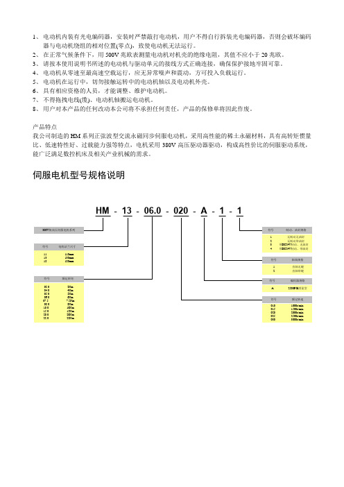
产品特点我公司制造的HM系列正弦波型交流永磁同步伺服电动机,采用高性能的稀土永磁材料,具有高转矩惯量比、低速特性好、过载能力强等特点,电机采用380V高压驱动器驱动,构成高性价比的伺服驱动系统,能广泛满足数控机床及相关产业机械的需求。
伺服电机型号规格说明HM - 13 - 06.0 - 020 - A - 1 - 1●选型指南电机型号电机简单参数适配驱动器功率模块型号启动倍数额定转矩额定转速额定电流HM-11-02.0-030-A-□-□2Nm 3000rpm 1.8A 15A 3.00HM-11-04.0-020-A-□-□4Nm 2000rpm 2.5A 15A 3.00HM-11-04.0-025-A-□-□4Nm 2500rpm 3.3A 25A 3.00HM-11-04.0-030-A-□-□4Nm 3000rpm 3.6A 25A 3.00HM-11-06.0-020-A-□-□6Nm 2000rpm 3.5A 25A 3.00HM-11-06.0-025-A-□-□6Nm 2500rpm 5.0A 40A 3.00HM-11-06.0-030-A-□-□6Nm 3000rpm 5.5A 40A 3.00HM-11-08.0-015-A-□-□8Nm 1500rpm 3.6A 25A 3.00HM-11-08.0-020-A-□-□8Nm 2000rpm 5.0A 40A 3.00HM-11-08.0-025-A-□-□8Nm 2500rpm 6.5A 40A 3.00HM-11-08.0-030-A-□-□8Nm 3000rpm 7.2A 40A 2.95HM-11-10.0-015-A-□-□10Nm 1500rpm 4.5A 25A 2.94HM-11-10.0-020-A-□-□10Nm 2000rpm 6.5A 40A 3.00HM-11-10.0-025-A-□-□10Nm 2500rpm 8.3A 40A 2.55HM-13-04.0-020-A-□-□4Nm 2000rpm 2.6A 15A 3.00HM-13-04.0-025-A-□-□4Nm 2500rpm 3.3A 25A 3.00HM-13-04.0-030-A-□-□4Nm 3000rpm 3.6A 25A 3.00HM-13-05.0-020-A-□-□5Nm 2000rpm 3.3A 25A 3.00HM-13-05.0-025-A-□-□5Nm 2500rpm 4.2A 25A 3.00HM-13-05.0-030-A-□-□5Nm 3000rpm 4.5A 25A 2.94HM-13-06.0-020-A-□-□6Nm 2000rpm 3.9A 25A 3.00HM-13-06.0-025-A-□-□6Nm 2500rpm 5.0A 40A 3.00HM-13-06.0-030-A-□-□6Nm 3000rpm 5.4A 40A 3.00HM-13-07.5-020-A-□-□7.5Nm 2000rpm 4.2A 25A 3.00HM-13-07.5-030-A-□-□7.5Nm 3000rpm 6.8A 40A 3.00HM-13-10.0-015-A-□-□10Nm 1500rpm 4.5A 25A 2.94HM-13-10.0-020-A-□-□10Nm 2000rpm 6.5A 40A 3.00HM-13-10.0-025-A-□-□10Nm 2500rpm 8.3A 40A 2.55HM-13-15.0-015-A-□-□15Nm 1500rpm 6.8A 40A 3.00HM-13-20.0-010-A-□-□20Nm 1000rpm 7.0A 40A 3.00HM-18-22.0-010-A-□-□22Nm 1000rpm 7.7A 40A 2.75备注:选型步骤:1、用户首先根据负载情况及机械加工要求,选择合适转矩及转速级别的伺服电机。

直线伺服电机Σ-7系列AC伺服驱动器资料编号 YASMNSV-16011C12345678910伺服电机的基本信息容量选择SGLG型伺服电机的规格、额定值、外形尺寸SGLF型伺服电机的规格、额定值、外形尺寸SGLT型伺服电机的规格、额定值、外形尺寸装置设计注意事项伺服电机的安装线性编码器的连接伺服电机和伺服单元的连接维护·检查型号:SGLG/SGLF/SGLT产品手册未经本公司的书面许可,严禁转载或复制本书的部分或全部内容。
本手册对∑-7系列AC伺服驱动器的直线伺服电机的选型、安装、连接、维护所需的信息进行了说明。
为了正确使用∑-7系列AC伺服驱动器,请认真阅读本手册。
并且,请妥善保管好本手册,以便需要时随时可以阅读和参考。
本手册各章的内容如下所述。
请根据需要参照。
iii伺服驱动器相关资料的关联图如下所示。
关联图中的编号与下页表格相对应。
请根据需要参照。
ivvviviiviiiixx◆本手册使用的基本术语本手册使用的术语如下所述。
◆注册商标等•MECHATROLINK 是MECHATROLINK 协会的商标。
•QR 码是株式会社DENSO WAVE 的商标。
•手册中提到的其它产品名称、公司名称等固有名词是各公司的商标、注册商标或商品名称。
本文中各公司的注册商标或商标未标注TM ,®标志。
◆图标的标注为使读者了解说明内容的区分,本书中设计了如下图标。
并在必要的地方使用这些图标。
表示操作或设定示例等。
表示补充事项或了解后有助于使用的信息。
ׁ㺛ݻ䈪᱄◆与安全有关的警告标记本手册使用以下标识术语,对预防人员伤亡及设备损坏需遵守的事项进行说明。
通过标识术语区分误操作时会产生的危害及损害程度。
内容均为与安全相关的重要内容,请务必遵守。
䙐⸛●表示如不避免可能会导致设备损坏的危险状况。
xi◆请务必遵守以确保安全⏹整体注意事项䙐⸛●请勿使用损坏、部件缺失的伺服单元及伺服电机。
●请在外部设置紧急停止回路,确保可在异常发生时切断电源并立即停止运行。
伺服电机规格书
一、引言
伺服电机作为现代机械控制系统中的重要组成部分,被广泛应用于
各种自动化设备和机械驱动系统中。
本规格书旨在详细描述我司所提
供的伺服电机的技术参数和性能特点,以确保客户对产品有全面准确
的了解。
二、产品概述
我司提供的伺服电机采用先进的控制算法和高性能的驱动器,具备
出色的响应速度和运动精度。
该伺服电机适用于各种机械设备,如机床、印刷机械、包装机器人等,并可与各种类型的控制系统无缝集成。
三、技术参数
1. 功率:伺服电机的额定功率为XX千瓦,有效负载范围为XX-
XX千克。
2. 额定转速:该伺服电机的额定转速为XXX转/分钟,可以根据客
户需求进行调整。
3. 输出转矩:伺服电机的额定输出转矩为XXX牛米,具备较大的
扭矩保留能力。
4. 绝对编码器分辨率:伺服电机采用高精度绝对编码器,分辨率达
到XXX脉冲/圈。
5. 控制方式:该伺服电机支持位置控制、速度控制和扭矩控制等多
种控制模式,可根据实际应用进行选择。
四、性能特点
1. 高精度定位:伺服电机通过精确的位置反馈和高频率的控制算法,实现非常精准的定位控制,定位误差小于X个脉冲。
2. 高响应速度:伺服电机具备快速响应的特点,能够在短时间内达
到稳定运行速度,提高生产效率。
3. 广泛应用:伺服电机适用于各种自动化设备和机械驱动系统,具
备良好的通用性和可扩展性,可满足多种应用需求。
4. 自我保护功能:伺服电机内置过流、过压、过热保护等功能,确
保电机在异常情况下能够安全运行,并延长电机的使用寿命。
五、选型建议
根据客户的具体需求和应用场景,我司建议选择适当的伺服电机型
号和配置。
以下是一些建议供参考:
1. 根据负载要求选择合适的额定功率和转矩参数。
2. 根据定位精度要求选择合适的编码器分辨率。
3. 根据控制方式选择适合的控制模式。
4. 根据环境条件选择具备防尘、防水等特性的伺服电机。
六、质量保证
我司所提供的伺服电机具备可靠的性能和稳定的质量,可提供长时间稳定运行,并且在产品发货后提供一定的售后服务。
具体的质量保证条款将根据合同协议进行约定。
七、结论
伺服电机作为自动化设备的核心部件之一,其技术参数和性能特点直接影响到整体控制系统的稳定性和精度。
我们相信,我司所提供的伺服电机将能够满足您的需求,并为您的设备带来更高的控制精度和生产效率。