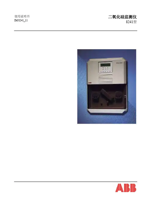
ABB分析仪技术协议
- 格式:doc
- 大小:71.50 KB
- 文档页数:6
采购设备技术协议《采购设备技术协议》甲方(采购方):____________________乙方(供应商):____________________根据《中华人民共和国合同法》及相关法律法规的规定,甲乙双方在平等、自愿、公平、诚实信用的原则基础上,就甲方采购乙方设备事宜,达成如下协议:一、设备名称、规格和数量1. 设备名称:____________________2. 设备规格:____________________3. 设备数量:____________________二、技术参数和质量标准1. 技术参数:____________________2. 质量标准:____________________三、价格和支付方式1. 设备价格:人民币(大写):____元整(小写):_____元。
2. 支付方式:甲方分期支付,具体支付方式和时间表见附件。
四、交货期限和地点1. 交货期限:乙方应按照甲方要求,在____年__月__日前将设备交付给甲方。
2. 交货地点:甲方指定的地点。
五、售后服务1. 乙方应提供设备的安装、调试和培训服务。
2. 乙方应自设备交付之日起,提供____年的免费保修服务。
3. 保修期结束后,乙方应继续提供有偿的维修服务。
六、违约责任1. 乙方迟延交货的,应按照迟延部分价款__%的标准向甲方支付违约金。
2. 乙方交付的设备不符合技术参数和质量标准的,乙方应承担相应的赔偿责任。
七、争议解决双方因履行本协议发生的争议,应首先通过友好协商解决;协商不成的,任何一方均有权向乙方所在地人民法院提起诉讼。
八、其他1. 本协议一式两份,甲乙双方各执一份。
2. 本协议自双方签字(或盖章)之日起生效。
甲方(盖章):____________________乙方(盖章):____________________签订日期:____年__月__日。
设备技术协议书甲方(买方):_____________________地址:_____________________________乙方(卖方):_____________________地址:_____________________________鉴于甲方有意向购买乙方提供的设备及其技术服务,双方本着平等互利的原则,经协商一致,达成如下设备技术协议:第一条设备及技术规格1.1 乙方同意向甲方提供以下设备及其技术服务(以下简称“设备”):(设备名称、型号、规格、数量等详细信息)1.2 乙方保证所提供的设备符合国家相关标准和甲方的技术要求。
第二条质量保证2.1 乙方保证所提供的设备是全新的,未使用过的,并且采用优质材料和先进工艺制造。
2.2 设备的质量保证期为自交付之日起____个月/年。
第三条交付与验收3.1 乙方应在合同签订后____天内将设备交付至甲方指定地点。
3.2 甲方应在设备交付后____天内完成验收,验收合格后签署验收确认书。
第四条价格与支付4.1 设备的总价为人民币____元(¥___)。
4.2 甲方应在合同签订后____天内支付总价的____%作为预付款。
4.3 余款在设备验收合格后____天内支付。
第五条技术服务与培训5.1 乙方应提供必要的技术支持和培训,以确保甲方能够正确操作和维护设备。
5.2 培训内容包括但不限于设备的操作、维护、故障排除等。
第六条违约责任6.1 如乙方未能按时交付设备或设备不符合约定的技术规格,甲方有权要求乙方支付违约金,违约金为设备总价的____%。
6.2 如甲方未能按时支付款项,应向乙方支付违约金,违约金为逾期支付金额的____%。
第七条争议解决7.1 双方因履行本协议所发生的任何争议,应首先通过友好协商解决。
7.2 如果协商不成,任何一方均可向甲方所在地人民法院提起诉讼。
第八条其他8.1 本协议一式两份,甲乙双方各执一份,具有同等法律效力。
8.2 本协议自双方授权代表签字盖章之日起生效。
采购合同技术协议书甲方(买方):_________乙方(卖方):_________鉴于甲乙双方就_________产品(以下简称“产品”)的采购事宜达成一致,特订立本技术协议,作为双方签订的《产品采购合同》(以下简称“主合同”)的组成部分,与主合同具有同等法律效力。
一、技术要求1. 乙方应保证所提供产品完全符合甲方的技术规格和性能要求,详见附件《产品技术规格书》。
2. 产品应通过相关质量检测,并符合国家及行业相关标准。
3. 产品在交付前应进行严格的出厂检验,并提供相应的检验报告。
二、技术支持与服务1. 乙方应在产品交付后提供不少于____个月的免费技术支持服务。
2. 在技术支持期内,乙方应对甲方提出的技术问题给予及时响应,必要时提供现场服务。
3. 乙方应向甲方提供产品的操作和维护培训,确保甲方人员能够熟练操作和维护产品。
三、技术资料1. 乙方应随产品一同提供完整的技术资料,包括但不限于产品说明书、操作手册、维修指南等。
2. 技术资料应清晰、准确,易于理解,以便甲方正确使用和维护产品。
四、质量保证1. 乙方应保证产品自交付之日起至少有____个月的质量保证期。
2. 在质量保证期内,如产品出现非人为因素导致的性能故障,乙方应负责免费维修或更换。
3. 对于因产品质量问题导致的损失,乙方应承担相应的赔偿责任。
五、知识产权1. 产品所涉及的全部知识产权归乙方所有,甲方仅获得产品的使用权。
2. 未经乙方书面授权,甲方不得以任何形式复制、传播或用于其他商业目的。
六、保密条款1. 双方应对在本技术协议履行过程中获知的对方商业秘密和技术信息予以保密。
2. 未经对方书面同意,任何一方不得向第三方披露相关信息。
七、争议解决凡因执行本技术协议所发生的一切争议,双方应通过友好协商解决;协商不成时,可提交至甲方所在地人民法院诉讼解决。
八、其他事项1. 本技术协议的任何修改和补充均需以书面形式经双方确认后方可生效。
2. 本技术协议的解释权归甲乙双方共同拥有。
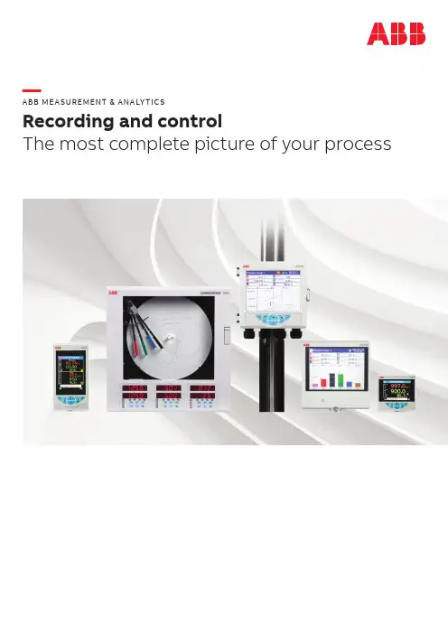
—ABB ME A SUREMENT & ANALY TIC SRecording and controlThe most complete picture of your process—Measurement made easyYour data, how, where and when you want it. ScreenMaster, ControlMaster and Commander are the names behind a comprehensive range of recording and control instrumentation from ABB that meet the demanding requirements of a broad range of applications in food and beverage, water and manufacturing.The range includes process controllers, digital indicators, chart recorders and paperless recorders. All sharing the same high standards of reliability and flexibility and capable of withstanding the harshest of process environments, they can be used in virtually any location.With a range of communications possibilities, including remote access, our controllers and recorders give you more power over your process than ever before.3—An option for every applicationcan cut the time and cost of deploying engineersto visit individual devices, ideal where skilledstaff are at a premium.We’ve also worked to use technology to take asmuch complexity as possible out of the operationof all our recording and control devices. With theirfull color, clear text displays and easy to useinterface, our ControlMaster process controllersand indicators make installing, commissioningand operating a control system quicker and easierthan ever.The same applies to our touchscreen RVG200paperless data recorder, where an extensive arrayof data recording and control possibilities can beachieved at the touch of a fingertip.With industry increasingly turning towards digitaltechnology, our range of recorders andcontrollers give you all the functionality you need,whether it’s greater control of your process or thestorage, retrieval and sharing of recorded data.By utilizing experience and expertise gainedthrough hundreds of applications across amultitude of industries, we have steadilyexpanded the capabilities of our devices to meetthe growing demands of today’s industrialapplications. Our SM500F and RVG200 paperlessdata recorders, for example, couple extensivesecurity with remote web server and mobiletechnology that offer system-size performancefrom a localized device. By enabling safe anytime,anyplace access to process data, these features4R ECO R D I N G A N D CO NTRO L—ABB ScreenMaster paperless recorders The digital era of data recording and analysisOur family of ScreenMaster paperless data recorders harness the power of digital technology to enable you to do more with your process data. Whether you want a field-mountable device that can be installed anywhere or slick and easy operation using the latest touchscreen technology, ABB’s ScreenMaster devices offer a versatile, secure and proven solution.Use anywhereWall, panel or pipe mounted options enable use in almost any location.Suitable for arduous environmentsNEMA 4X and IP66 protection enables installation in even the wettest or dirtiest conditions.Powerful yet simpleSimple menu interfaces make finding and viewing data easy, with multiple display formats offering a wide choice of viewing options.Flow recordingFlow totalizers enable instantaneous flow rates to be totalized and recorded. An automatic reset capability enables daily, weekly and monthly flow volume reports to be generated and alarms to be raised if predefined flow limits are exceeded.Powerful mathsMath and logic functions enable calculation of equations such as averages and deviations. Results can be displayed, recorded and used to drive alarms and totalizers.Extensive security featuresMeasures include a comprehensive audit log that records configuration changes, calibration changes, system events and other items key to data security. All entries are detailed with operator identification. Operators can securely annotate the chart with comments and signatures. Both recorders can form part of a system fully compliant to 21 CFR Part 11.Ethernet communicationsEthernet communications enable access toarchived data and email facilities. Using the latest telecoms tech the Ethernet features can be used even when a recorder is in a remote location.Remote process monitoringRemote access to a ScreenMaster is possible via the use of any standard web browser. Detailed real-time information is available for current alarm and totalizer conditions, memory card status and many other key process details. Email notificationKeep up to date with the latest process alarms or critical process events with email notifications which can be sent automatically to your PC or smartphone.Real-time data communicationScreenMaster recorders can communicate the process values being monitored to a DCS, SCADA, PLC or other similar system. Alternatively, data values can be communicated to a ScreenMaster for display to the operator and secure logging.Batch recordingA batch recording option enables batch numbers and product type information to be recorded alongside process data. With ABB’s DataManager Pro software, collected batch records can be accessed by searching for their batch number orbatches with common attributes identified.+ -x5SM500FField-mountable paperless recorder Featuring up to 7 process inputs, 12 recording channels and available with wall, panel and pipe mounting options, the SM500F field-mountable paperless recorder provides a truly simple recording solution that can be used anywhere, anyhow and by anyone.Its fully sealed IP66 and NEMA 4X enclosure make it ideal for even the most hostile environments, including hosedown and dusty applications.RVG200Touchscreen paperless recorderThe RVG200 recorder takes the established operating and securitybenefits of the ScreenMaster range onestep further. Up to 24 process signals can be connected to the RVG200’s analog inputs or transferred to it via digital communications. Features include: • Touchscreen ‘swipe’ operation• Front and rear USB ports for connecting peripheral devices, including a barcode scanner and keyboard • Customizable views• Steam energy calculations • Remote operation • GPS interfaceDataManagerProPowerful data analysis tool that helps you get more from your dataABB’s DataManager Pro advanced data review software opens new possibilities for collecting, interrogating andpresenting recorded data. The software creates a database of recorded data providing secure long-term storage andenabling instant access to data.6R ECO R D I N G A N D CO NTROL—ABB ControlMaster universal process controllers and indicators Control made easyWhether you’re a plant or process manager, electrical engineer, process operator or maintenance engineer, the future of process control instrumentation starts here.ABB has used its experience in controllers and indicators to create the ControlMaster family of process control instruments, offering an intuitive, simple and powerfulsolution for a wide range of process control applications.Scalable hardware and software functionalityI/O, functionality and control template availability is expanded easily with additional plug-and-play input modules and function keys, enabling a singleControlMaster unit to be adapted to handle anything, from basic to complex control applications.Full environmental protectionWith fully-sealed IP66 and NEMA 4Xenclosures or front panels, all ControlMasters offer full protection against water and dust ingress, enabling them to be used in even the most arduous operating conditions.Enjoy the flexibility of field-mountEnjoy the benefits of devices that you can locate practically anywhere, with the field-mounted CMF310 controller and CMF160 indicator. Able to be wall or pipe-mounted out of the box, they can be installed and commissioned in a fraction of the time and cost needed for adapting panel-mounted units.Panel-mount indicatorsThe CM15 is a feature-packed 1/8 DIN universal process indicator, with totalization, level, math, logic,counter and alarm functions.CMF160 field-mount indicatorCM15 panel-mount indicatorDiscover moreCMF310 field-mountcontrollerCM15panel-mountindicator CMF160field-mountindicatorPanel-mount controllers7ConfigPilot is the configuration platform for the entire range of ABB’s ControlMaster controllers and indicators. With an identical menu structure to the ControlMaster, ConfigPilot is instantly familiar. Configurations can be created from scratch off-line or read from a ControlMaster device. Once complete a configuration can be written to a ControlMaster via its front panel IrDA port or saved for future use. In addition ConfigPilot’s reporting capabilities hugely simplify creation of configuration documentation.Get up and running quickly with ConfigPilotPanel-mount controllersAvailable in 1/8, 1/4 and 1/2 DIN options, our ControlMasterpanel-mount controllers offer a simple, ready to use control solution.Suitable for basic to demanding applications, functionalityincludes cascade, feed forward, adaptive, predictive and ratio control strategies, plus Ethernet, RS485, Modbus TCP/RTU and a web server for remote process monitoring.CM10 1/8 DIN panel-mount controller CM50 3 x 6 DIN panel-mount controllerProfile controlProfile control enablessetpoint profiling for thermal processing applications. Two versions are available; a basic single program version and an advanced, multi-program version with sequencing. Profile-specific displaysprovide a clear overview of the profile progress, including program name and timeremaining, with more detailed information available at the press of a button.Advanced functions The ControlMaster range gives you even greater functionality. Features include math, totalization, a frequency input, logic, gain scheduling, split output, valve control and real time alarms.Template based configuration ControlMasterconfiguration is vastly simplified by using application templates. Selecting the template best suited to your process requirements configures I/O and control functionality automatically while display templates are also selected automatically.c8R ECO R D I N G A N D CO NTROL—ABB Commander circular chart recorders The tried and tested paper chart recorderRobust and easy to use, our Commander circular chart recorders have established a reputation for their reliable performance in a host of industrial applications including water and waste water treatment, food, pharmaceuticals and tyre production.A range of advanced functions, plus NEMA 4X and IP66 protection, makeCommander recorders the first choice wherever paper chart recording is required.Recording versatilityStatus at a glanceIntuitive operationsystem prevents unauthorized access to configuration menus.Math and logicUser configurable math functions, mass flow calculations and totalizers are all fully supported. The logic capability allowsinterlocking and the integration of discrete and continuous functions to solve a wide range of process problems.Discover more9MODBUS RS485 communications Communication with PCs or PLCs is achieved via the RS485 serial communications link, enabling the Commander 1900 to serve as the front end of plant-wide data acquisition systems. Using the MODBUS RTU protocol, all process inputs and other variables can be read continuously by a host PC running on a wide variety of standard SCADA packages.Install anywhereThe unit can be wall/pipe or panel mounted anywhere in the plant and, with its rating of NEMA 4X and IP66, it can be subjected to rigorousBuilt to meet your process’s needsA high level of I/O fitted as standardenables Commander recorders tomeet the requirements of mostprocesses out of the box. In addition,plug-and-play modules can be addedat any time to further extend arecorder’s I/O capability.Timers and clockTwo real-time eventstriggered by the recorder’sclock can be configured tooperate relays, start/stopthe chart or enable otheractions within the record.Options for everyapplicationC1900RC circular chartrecorder / controllerC1950 pasteurizerrecorder / controllerC1300 municipal recorder withflow totalizer displayC1960 Multi-recipeprofile recorder / controllerIntegrated PID loopsOffering dual integrated PIDloops, the C1900 chart recordercan be utilized as both a recorderand controller, eliminating thespace and cost associated withusing separate devices.10R ECO R D I N G A N D CO NTRO L—The ABB controller and recorder range Comprehensive solutions for food and beverage, water and manufacturing Water and wastewaterFood and BeverageKnowing what happens where, when and for how longare key considerations in making sure that food andbeverage products are produced to the right quality andunder the correct conditions. Our recording and controlequipment can be used in a wide variety of applicationsto ensure production processes perform properly and tohelp keep track of every product:AbstractionBatch recording PasteurizationSpirit distillation andbrewingCarbonation controland monitoringTemperature monitoring in fridges,freezers and cold roomsSteam usage monitoring Retort control and monitoringRVG200 recorder guides and videosScan this QR code to view anddownload application guides andvideos explaining how the RVG200can be used across differentindustrial applications.SM500F recorder guides and videosScan this QR code to view and downloadapplication guides and videos explaininghow the SM500F can be used acrossdifferent industrial applications.Cooking and bakingGuides and videos11Heat treatmentHeat treatment of metals for the aerospace,automotive and general engineering industriesmust be controlled rigorously to ensure thereliability of the parts being produced. Oursolutions include the ControlMaster range ofprocess controllers, plus the RVG200 paperlessrecorder with AMS2750 compliant inputs.Tyres and rubberOur multi-recipe profile controllers can help youachieve the precise pressure, temperature andtime control demanded during the curing of tyresand other rubber products.MarineMarine operators are subject to increasinglystrict emissions legislation governing theiremissions to air and sea. Our RVG200 paperlessdata recorders with GPS can be used to satisfyMARPOL regulations requiring the accuratecontrol and recording of bilge water dischargesfrom ships.PharmaceuticalsThe use of electronic devices in pharmaceuticalsproduction is strictly regulated to ensure thehighest levels of product quality and safety. OurSM500F and RVG200 paperless data recorders,together with our DataManager Pro data analysissoftware, can help you comply with theregulations, including the FDA’s 21CFR Part 11rules governing data security.Electrical power monitoringOur SM500F and RVG200 paperless datarecorders provide an ideal solution for localizedenergy consumption monitoring. Using collecteddata, you can find ways to reduce your energycosts and cut your carbon emissions.CMF310 controller guides and videosScan this QR code for application guidesand videos about the CMF310 field-mountcontroller and how it can be used acrossdifferent industrial applications.ControlMaster panel-mount controllersguides and videosScan this QR code to see how ourControlMaster panel-mount controllerscan help to solve a broad range ofapplication challenges.P B /R e c o r d e r s a n d C o n t r o l l e r s -E N R e v . B 06.2019—ABB LimitedMeasurement & Analytics Howard Road Eaton Socon St. NeotsCambridgeshire PE19 8EUTel: +44 (0)1480 475321ABB Inc.Measurement & Analytics 125 E. County Line Road Warminster PA 18974 USATel: +1 215 674 6000© Copyright 2019 ABB. All rights reserved.Specifications subject to change without notice.。
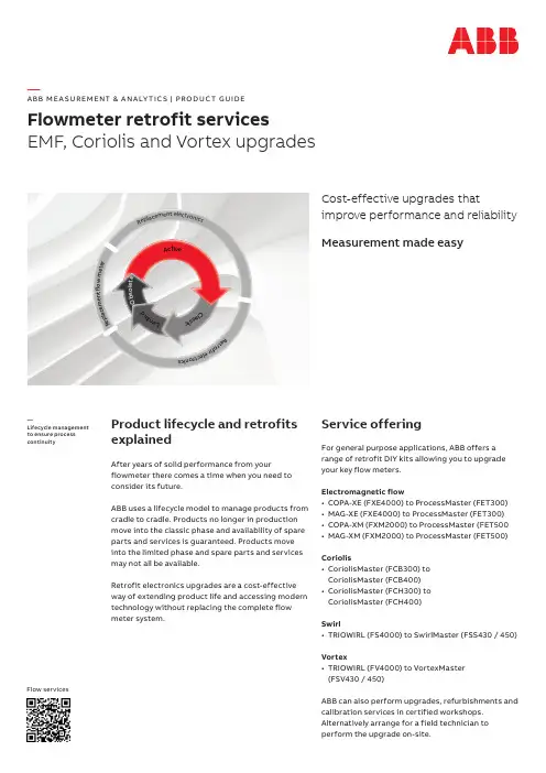
A ct i v eC l a s s i c L i mi t e dR e pl a c e me n t e l e c t r o ni c s Re tr o f i r e l e c t r on i c sR ep l a c e m e n t f l o w m e t e r O b s o l e t e —A B B M E A SU R EM ENT & A N A LY TI C S | PRO DUC T G U I DEFlowmeter retrofit servicesEMF, Coriolis and Vortex upgradesCost-effective upgrades thatimprove performance and reliability Measurement made easyProduct lifecycle and retrofits explainedAfter years of solid performance from yourflowmeter there comes a time when you need to consider its future.ABB uses a lifecycle model to manage products from cradle to cradle. Products no longer in production move into the classic phase and availability of spare parts and services is guaranteed. Products move into the limited phase and spare parts and services may not all be available.Retrofit electronics upgrades are a cost-effective way of extending product life and accessing modern technology without replacing the complete flow meter system.Service offeringFor general purpose applications, ABB offers a range of retrofit DIY kits allowing you to upgrade your key flow meters.Electromagnetic flow• COPA-XE (FXE4000) to ProcessMaster (FET300)• MAG-XE (FXE4000) to ProcessMaster (FET300) • COPA-XM (FXM2000) to ProcessMaster (FET500• MAG-XM (FXM2000) to ProcessMaster (FET500) Coriolis• CoriolisMaster (FCB300) to CoriolisMaster (FCB400) • CoriolisMaster (FCH300) to CoriolisMaster (FCH400)Swirl• TRIOWIRL (FS4000) to SwirlMaster (FSS430 / 450) Vortex• TRIOWIRL (FV4000) to VortexMaster (FSV430 / 450)ABB can also perform upgrades, refurbishments and calibration services in certified workshops. Alternatively arrange for a field technician to perform the upgrade on-site.—Lifecycle management to ensure process continuityFlow servicesBenefits of ABB retrofitsMaximize capital investments Extend product life time.Service availabilityKeep your flowmeter modern and guarantee access to all spare parts and services.Warranty extensionWork performed by ABB provides 6 months warranty for complete system and 12 months for kit of parts.Modernize processesAccess state of art technology.Figure 1 EMF Before and after upgradeP G /S R R 250–E N R e v . B 01.2018—We reserve the right to make technical changes or modify the contents of this document without prior notice. With regard to purchase orders, the agreed particulars shall prevail. ABB does not accept any responsibility whatsoever for potential errors or possible lack of information in this document.We reserve all rights in this document and in the subject matter and illustrations contained therein. Any reproduction,disclosure to third parties or utilization of its contents – in whole or in parts – isforbidden without prior written consent of ABB. ©ABB 2018All rights reserved—To find your local ABB contact, visit:/contactsFor more information visit:/measurement3KXS240011R2401—Scalable and flexible management of product and resources。
技术协议承诺函尊敬的合作伙伴:您好!首先,我谨代表我方对您长期以来给予我们的支持表示衷心的感谢!为了更好地为您提供优质的产品和服务,确保双方在技术合作过程中实现共赢,我方特此向您发出本。
一、技术协议概述1.1 本技术协议(以下简称“本协议”)由以下双方签订:(1)甲方:(公司名称),以下简称“甲方”;(2)乙方:(公司名称),以下简称“乙方”。
1.2 本协议的目的在于明确双方在技术合作过程中的权利、义务和责任,确保项目顺利进行,实现双方共同发展。
1.3 本协议涉及的技术合作范围包括但不限于:产品研发、技术咨询、技术服务、技术转让等。
二、技术合作协议2.1 技术研发(1)甲方应根据乙方提供的技术需求,组织研发团队进行技术研发,确保研发成果满足乙方的要求。
(2)乙方应协助甲方进行技术研发,提供必要的技术支持和指导。
(3)双方应共同参与技术研发过程中的重要节点评审,确保研发进度和质量。
2.2 技术咨询与服务(1)甲方应根据乙方的需求,提供专业、及时的技术咨询服务,解答乙方在技术使用过程中遇到的问题。
(2)乙方应定期向甲方反馈技术使用情况,提出改进意见和建议,共同优化技术方案。
2.3 技术转让(1)甲方应对乙方提供的技术资料和成果予以保密,不得向第三方泄露。
(2)乙方应对甲方提供的技术资料和成果予以保密,不得向第三方泄露。
(3)双方在技术转让过程中应遵循平等、自愿、有偿的原则,明确技术转让的内容、范围、方式、期限等。
2.4 技术成果权益(1)双方共同研发的技术成果,应按照约定分配权益。
(2)双方独立拥有的技术成果,应分别享有其权益。
(3)双方在技术合作过程中获得的国家知识产权,应按照约定分配权益。
三、技术合作协议的履行3.1 双方应严格按照本协议的约定履行各自的权利和义务。
3.2 双方应相互配合,共同解决技术合作过程中出现的问题,确保项目顺利进行。
3.3 双方应定期召开技术合作会议,汇报技术进展情况,协调解决合作事宜。
25. 如何选择ABB PLC的通讯接口和协议?甲方:____________________________乙方:____________________________11 为明确双方权利与义务,确保项目顺利进行,依据相关法律法规,经双方协商一致,就如何选择 ABB PLC 的通讯接口和协议事宜,达成如下协议:111 本协议旨在规定双方在选择及使用 ABB PLC 通讯接口和协议过程中的责任、义务以及合作方式。
112 本协议自签订之日起生效,有效期至项目完成并通过验收之日止。
113 在协议有效期内,双方应遵守所有条款,并积极履行各自职责。
114 任何一方违反协议规定,均需承担相应法律责任。
115 双方同意通过友好协商解决因执行本协议而产生的争议。
116 若协商不成,则提交甲方所在地仲裁委员会按照其当时有效的仲裁规则进行仲裁。
117 本协议未尽事宜,双方可另行协商并签订补充协议,补充协议与本协议具有同等法律效力。
118 本协议正本一式两份,甲乙双方各执一份,具有同等法律效力。
12 为了满足项目需求,选择适合的 ABB PLC 通讯接口和协议至关重要。
以下为选择时需要考虑的关键因素:121 设备兼容性:确保所选通讯接口能够与现有设备无缝对接。
122 通讯速度:根据实际应用需求选择能满足数据传输速率要求的接口类型。
123 网络安全性:评估不同通讯协议的安全性能,选择能够提供可靠保护措施的方案。
124 易用性:考虑到后期维护与操作便捷性,优选易于配置管理的接口和协议。
125 成本效益比:综合考量初期投入与长期运行维护费用,选择性价比高的选项。
126 技术支持:优先考虑厂商能提供全面技术支持服务的产品。
127 扩展能力:预留未来升级空间,确保系统具有良好的扩展性。
128 标准化程度:遵循国际或行业通用标准,避免因采用非标技术导致后续兼容问题。
129 市场占有率:参考同类产品市场反馈情况,选择口碑良好且广泛应用的解决方案。
电气仪表技术协议书甲方(委托方):_____________________乙方(受托方):_____________________鉴于甲方需要对电气仪表进行专业的技术维护和升级,乙方具备相应的技术能力和资质,经双方协商一致,特订立本技术协议书。
第一条服务内容1.1 乙方将为甲方提供电气仪表的定期检查、维护和故障排除服务。
1.2 乙方将根据甲方需求,对电气仪表进行必要的升级和改造,以满足甲方的业务发展和技术更新需求。
第二条服务标准2.1 乙方应保证所提供的服务符合国家及行业相关标准和规范。
2.2 乙方应确保服务过程中使用的技术和设备符合安全、环保要求。
第三条服务期限3.1 本协议书服务期限自____年____月____日起至____年____月____日止。
第四条费用及支付方式4.1 甲方应按照本协议书约定向乙方支付服务费用,具体金额为人民币(大写):____________________元。
4.2 服务费用的支付方式为:____________________。
第五条双方权利与义务5.1 甲方有权监督乙方的服务质量,并要求乙方按照约定提供服务。
5.2 乙方应保证所提供服务的专业性和及时性,不得无故拖延或拒绝提供服务。
5.3 甲方应按时支付服务费用,不得拖欠。
5.4 乙方应对甲方提供的电气仪表信息保密,未经甲方同意,不得向第三方披露。
第六条违约责任6.1 如一方违反本协议书约定,应承担违约责任,并赔偿对方因此遭受的损失。
第七条争议解决7.1 本协议书在履行过程中如发生争议,双方应首先通过友好协商解决;协商不成时,可提交甲方所在地人民法院诉讼解决。
第八条其他8.1 本协议书未尽事宜,由双方协商解决。
8.2 本协议书一式两份,甲乙双方各执一份,具有同等法律效力。
甲方(盖章):_____________________授权代表(签字):___________________日期:____年____月____日乙方(盖章):_____________________授权代表(签字):___________________日期:____年____月____日。
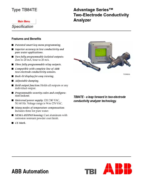
ABB AutomationTB84TE - a leap forward in two-electrode conductivity analyzer technology.TC02662AFeatures and Benefitss Patented smart key menu programming.s Superior accuracy in low conductivity and pure water applications. s Two fully programmable isolated outputs: Zero to 20 mA/four to 20 mA.s Three fully programmable relay outputs.s Compatible with complete line of ABB two-electrode conductivity sensors.s Back-lit display for easy viewing.s Adjustable damping.s Hold output function: Holds all outputs or any individual output.s Programmable security codes and configura-tion lockout.s Universal power supply: 120/240 VAC,50/60 Hz. Voltage range is 94 to 276VAC.s Many modes of temperature compensation: Includes three for pure water.s NEMA 4X/IP65 housing: Cast aluminum with corrosion resistant powder coat finish.s CE Mark.Advantage Series™Two-Electrode Conductivity AnalyzerType TB84TESpecificationMain MenuThe ABB Type TB84TE Advantage™ Conductivity Ana-lyzer is a unique and advanced microprocessor-based instrument. Smart keys on the front panel provide local programming of all analyzer functions. Easy-to-follow instructions appear above each smart key. A secondary display clearly defines each menu option during pro-gramming. When the analyzer is in the normal operating mode, the secondary display shows several useful parameters. This innovative, user-friendly inter-face provides straightforward analyzer operation, configuration, and calibration. Standard outputs include two isolated analog (current) outputs and three relay out-puts. The analog outputs can be configured for the process variable (PV) and/or temperature. The relay out-puts can be configured for the PV, temperature, diagnostics, cycle timer controller, or sensor cleaner.The Type TB84TE analyzer is compatible with all ABB two-electrode conductivity sensors. It automatically ranges itself across three decades of conductivity reso-lution for any single cell constant. Two-electrode sensors provide accurate conductivity measurements in lower conductivity solutions and pure water. Precalibra-tion is accomplished by programming the cell constant of the sensor during configuration. Careful selection of electrode materials (316 stainless steel standard), insu-lator materials, and electrode spacing provides rugged sensors and reduced sensor maintenance. Sensor diagnostics include sensor polarization, and open or shorted temperature compensator/cabling.The Type TB84TE analyzer meets current CE,NEMA4X, and IP65 requirements.Two-Electrode Sensor CompatibilityThe analyzer accepts inputs from all ABB two-electrode sensors. A menu choice during configuration makes changing from one cell constant to another easy. No jumpers or manual adjustments are required.Two-Electrode Sensor RangesBasic or Advanced ProgrammingThe basic or advanced programming mode can be cho-sen at the time of purchase. The advanced mode has an expanded set of functions intended for complex applications. Separating the basic and advanced modes simplifies setup and calibration activities. The advanced configuration choices are:•Concentration analyzer: User-defined through a six-point conductivity versus concentration linearcurve fit where output follows concentration. Engi-neering unit choices are percent (%), parts permillion (ppm), parts per billion (ppb), and user-defined.•Temperature compensation types: Pure water neutral salt, pure water trace base, pure water trace acid, user-defined function generator.•Analog pulse diagnostic output.•Nonlinear output: User-defined through a six-point conductivity versus desired current output that best fits the nonlinear relationship.•Expanded relay functions and flexibility. Analog OutputsThe analyzer has two isolated analog outputs (AO1 and AO2). Each is user-configurable as either a zero to 20 or a four to 20-milliampere signal. AO1 is dedicated to the PV while AO2 is configurable for either the PV or temper-ature. A two-point calibration method applies to both analog outputs. This allows adjustment of the analog out-puts to compensate for other devices in the loop that may not be calibrated. Entering the PV or temperature end-points in reverse order allows for reverse-acting outputs.A capacitive type lag, applied via the damping function, is useful in process environments where noise is present. Damping is supported for both analog outputs and the displayed PV, and has a maximum value of 99.9seconds. One damping value affects both analog outputs and the displayed PV in basic configurations. Individual damping values affect each analog output and the displayed PV in advanced configurations. Relay OutputsThe analyzer has three relay outputs available (RO1, RO2, RO3). Each is jumper selectable as either nor-mally open (NO) or normally closed (NC). RELAY, followed by the corresponding relay number, appears on the display when a relay activates. The functionality of each relay output depends on the configuration mode. T able 1 shows the possible functionality of each relay output for basic and advanced configurations. Advanced programming allows all function choices shown in Table 1 for each of the three relay outputs.Cell Constant ConductivityRangeDisplayResolutionAutorange0.010 to199 m S/cm 0.001 m S/cm 1.999 to 19.99 to199.9 m S/cm0.100 to1,999 m S/cm 0.01 m S/cm19.99 to199.9 to1,999 m S/cm1.000 to19.99 mS/cm 0.1 m S/cm199.9 m S/cm to1,999 m S/cm to19.99 mS/cm2High and low alarms can be chosen for the PV and tem-perature in either degrees Celsius or degrees Fahrenheit. Each has a user-selectable deadband and time delay designed to control relay functions and pre-vent problems like relay chatter. The diagnostic relays can be linked to sensor diagnostics, analyzer diagnos-tics, or all diagnostic conditions. The high and low cycle timer has adjustable set points, cycle time, and on time. The cycle timer allows a waiting period to see the results of chemical addition by interrupting the feed. The sensor cleaner feature provides for cycle time, on time, and recovery time programming. This makes set up and operation of the analyzer with the ABB hydraulic sensor cleaner or Model TB18 Safe-T-Clean® Sensor Valve easy and trouble free.DiagnosticsThe Type TB84TE analyzer constantly monitors both the sensor and the analyzer. This helps to ensure reli-ability and accuracy. Upon detection of a diagnostic condition, the analyzer provides diagnostic notification by flashing FAULT on the display and supplying a pulse on AO1 (if activated). Pressing the FAULT info smart key stops FAULT from flashing and provides, on the secondary display, a short description and fault code. FAULT remains on until resolution of the problem. Sen-sor faults that activate the diagnostic notification are: •Sensor polarization.•Shorted or open temperature compensator.Hold OutputThe analyzer has a hold output state that improves plant safety and process integrity during maintenance and calibration. When activated, HOLD appears at the top of the display. Upon release of the hold state, HOLD disappears. When the sensor cleaner option is chosen, the analyzer provides the option of holding all analog and relay outputs during the cleaning cycle. The analog outputs can be held to any preselected level. The relay outputs can be held individually to any active or inactive state. This is useful for checking and exercising any external devices connected to the analyzer. Diagnostic PulseThe analog output is fully scalable over any conductivity or concentration range. Advanced configurations allow pulsing of AO1 during a diagnostic condition.When the diagnostic pulse is active, the output is modu-lated for one second out of a six-second repeating cycle to a configuration selectable level ranging from one to 100percent of span (0.16 to 16 milliamperes for a four to 20-milliampere output or 0.20 to 20milliamperes for a zero to 20-milliampere output). Should the actual output of the analyzer be below 12 milliamperes, the pulse will add current; if the actual output is at or above 12 milli-amperes, it will subtract current. This provides remote notification of a problem with proper configuration of a digital control system (DCS), programmable logic con-troller (PLC), or chart recorder.Temperature CompensationThe T ype TB84TE analyzer is compatible with eitherPt100 or PT1000 temperature compensators. The auto-matic temperature compensation options are: manual, automatic for potassium chloride (KCl), user-entered coefficient in percent per degree Celsius, a user-defined function generator, and trace acid, trace base, and neu-tral salt for pure water.CalibrationSmart key programming makes analyzer calibration accurate and efficient. Process calibration is a straightforward one-point smart calibration resulting in either a slope adjustment, offset adjustment, or a com-bination of adjustments. Selecting the reset calibration state results in the calibration defaulting to the original factory calibration. A one-point smart temperature cali-bration also exists. This calibration adjusts either the temperature slope, offset, or a combination. A special edit calibration state allows manual editing or adjusting of the calibration data. This feature is useful during a startup where a large number of similar loops are being set up and calibrated at the same time. Calibration of the zero to 20-milliampere or four to 20-milliampere out-put is allowed via an easy two-point procedure. Programmable Security CodeThe analyzer has one three-digit security code. Menu-selectable choices allow the security code to be applied to none of or any combination of these menu choices: calibrate, output/hold, setpoint/tune, and configure.Table 1. Relay Output Functionality1NOTES:1.· = available.2.If a relay output has been configured as a sensor cleaner, no otherrelay output can be used for this function.3SpecificationsType Conductivity analyzerInput Voltage120/240 VAC, 50/60 HzRange:94 to 276 VACInstallation category:IIPower Consumption17 VA max.Input TypeABB 2-electrode conductivity sensorsInput RangeConductivity:0.000 m S/cm to 19.99 mS/cmConcentration:0.000 to 1,999 digits (engineeringunits configurable)Display ResolutionConductivity:0.001 m S/cm, 0.01 m S/cm, 0.1m S/cm (cell constant dependant) Concentration:0.001 digits (configurable)T emperature:1°C, 1°FTemperature Compensation TypesPt 100, Pt 1000Temperature CompensationManual (0.1N KCl based)Automatic, configurable as: standard (0.1N KCl based), user-defined coefficient (0 to 9.99%/°C), pure water - neu-tral salt, pure water - acid, pure water - base, user-defined function generatorAnalog Output Ratings2, completely isolated 0 to 20 mA or 4 to 20 mA outputs, 750 W max. load value, AO1 fixed to PV, AO2 configurable to either PV or temperatureAO1Conductivity/concentration - Isolated 0 to 20 mA or 4 to 20mA, direct or reverse-acting, linear and nonlinear, con-figurable across full rangeMinimum span:1.00 Cell Constant100.0 m S/cm0.10 Cell Constant10.00 m S/cm0.01 Cell Constant 1.000 m S/cmConcentration5% max. concentration rangeMaximum span:1.00 Cell Constant19.99 mS/cm0.10 Cell Constant1,999 m S/cm0.01 Cell Constant199.9 m S/cmConcentration1,999 digitsAO2Conductivity/concentration/temperature (°C or °F) - Iso-lated 0 to 20 mA or 4 to 20 mA, direct or reverse-acting, configurable across full rangeMinimum span:1.00 Cell Constant100.0 m S/cm AO2 (continued)0.10 Cell Constant10.00 m S/cm0.01 Cell Constant 1.000 m S/cmConcentration5% max. concentration rangeTemperature10°C, 18°FMaximum span:1.00 Cell Constant19.99 mS/cm0.10 Cell Constant1,999 m S/cm0.01 Cell Constant199.9 m S/cmConcentration1,999 digitsTemperature300°C, 540°FRelay OutputsForm C, SPDT relays that are jumper selectable as either normally open or normally closed. Refer to T able 1 to see functionality of each relay output in basic and advanced configurations.Ratings:Max. AC capacity100 VA, 240 VAC, 3 AMax. DC capacity50 W, 24 VDC, 2 AHigh and low set points (basic and advanced configura-tions):Source: Conductivity and concentrationHigh/low/deadband Software configurableDelay value range00.0 to 99.9 min.Source: T emperature (°C or °F)High and low range0° to 300°C or 32° to 572°FDeadband range0° to 10°C or 0° to 18°FDelay value range00.0 to 99.9 min.High or low cycle timer (advanced configurations only):Source: conductivity and concentrationTurn on range Software configurableCycle time and on time range00.0 to 99.9 min.Sensor cleaner (advanced configurations only):Cycle time range00.0 to 99.9 hrOn time range00.0 to 99.9 min.Recovery time range00.0 to 99.9 min.Nonlinearity and RepeatabilityConductivity:Display±1.0% of measurement rangeper decadeOutput±0.02 mA at full scale outputsettingsTemperature:1°CMaximum Sensor Cable Length30.5 m (100 ft)Turn On Time 2 secs typical, 4 secs max.45Installation AccessoriesWiring and Installation DiagramsFigures 1, 2, 3, 4, and 5 show the wiring and installation diagrams.Load Resistance Range (analog outputs)750 W max.DampingContinuously adjustable from 00.0 to 99.9 secsDynamic Response 3 sec for 90% step change with 00.0 sec dampingMounting Position EffectNoneEnvironmental T emperature:Operating -20° to 60°C (-4° to 140°F)Storage-40° to 70°C (-40° to 158°F)Humidity (operating and storage):Will meet specifications to 95% RHHousingNEMA 4X and IP65, aluminum alloy with corrosion resis-tant powder coating Conduit Connection5 total, 2 each 0.875-in. holes in enclosure that accept ½-in. hubs, 3each 0.600-in. holes that accept PG9 hubs Size (½ DIN)h x w x d:144.0 x 144.0 x 171.0 mm (5.67 x 5.67 x 6.73 in.)Min. panel depth:144.8 mm (5.70 in.)Max. panel thickness:9.5 mm (0.38 in.)Panel cutout:135.4 (+1.3, -0.8) by 135.4 (+1.3, -0.8) mm(5.33 (+0.05, -0.03) by 5.33 (+0.05, -0.03) in.)Weight2.1 kg (4.6 lbs),3.4 kg (7.5 lbs) with pipe mounting hardwareAgency CertificationsCSA:Class I; Division 2, Groups A, B, C, and D Class II; Division 2, Groups E, F , and G Class III; Division 2FM: NonincendiveClass I; Division 2, Groups A, B, C, and D Class II; Division 2, Groups F and G Class III; Division 2EMC RequirementsCE certified - complies with all applicable European Com-munity product requirements, specifically those required to display the CE marking on the product nameplate.SPECIFICA TIONS SUBJECT TO CHANGE WITHOUT NOTICE.Number Description4TB9515-0123Panel mounting kit 4TB9515-0124Pipe mounting kit 4TB9515-0125Hinge mounting kit 4TB9515-0156Wall mounting kit 4TB9515-0165Cable grip for ½-in. hubs 4TB9515-0191Cable grip for PG9 hubs4TB9515-0198Complete cable grip kit (2 each ½-in. and 3 each PG9)Figure 2. Panel Mounting 6Figure 5. Pipe Mounting7Form WTPEEUS520006A0 Litho in U.S.A.August2000Copyright © 2000 by ABB Automation Inc., as an Unpublished Work, All Rights Reserved ® Registered T rademark of ABB Automation Inc.™ T rademark of ABB Automation Inc.ABB Instrumentation Ltd Oldends Lane Stonehouse, Glos.England, GL10 3TATel: +44 (0) 1453-826-661Fax: +44 (0) 1453-827-856ABB Automation Products GmbH Heerdter Landstr. 193D-40549 Düsseldorf Tel: +49 (211) 50077300Fax: +49 (211) 50077333ABB Automation Inc 2175 Lockheed Way Carson City NV 89706 USAT el: +1 (0) 775-883-4366Fax: +1 (0) 775-883-4373The Company ’s policy is one of contin-uous product improvement and the right is reserved to modify the informa-tion contained herein without notice.Ordering Guide®Mylar is a registered trademark of E. I. DuPont de Nemours Company, Incorporated.1.This specification covers only the T ype TB84TE analyzer.2.Consult factory for status.。
Protection and Control Relay620 SERIES ANSIProtocol Implementation ConformanceStatement for the IEC 61850 interface in 620series ANSI1MRS239339 A Protection and Control Relay620 SERIES ANSI Protocol Implementation Conformance StatementTable of Contents1About this document (3)1.1Read it first! (3)1.2Document information (3)2Safety Information (3)3Abbreviations, Definitions and Conventions (4)3.1Abbreviations (4)3.2Definitions (4)4Reference Documents (5)5Introduction (6)5.1Scope of this statement (6)6ACSI conformance statement (7)6.1General (7)6.2ASCI basic conformance statement (7)6.3ACSI models conformance statement (8)6.4ACSI service conformance statement (9)7SCL conformance statement (12)8PICS – Protocol conformance statement (12)8.1Profile conformance (12)8.2MMS Conformance (13)9PIXIT (14)10Appendix A: Index of Tables (14)1 About this document1.1 Read it first!Before attempting any operation with IED from 620 series ANSI, read carefully the IED documentation first.This document is addressed to anyone who needs to interact with 620 series ANSI and its IEC 61850 features in more detail.1.2 Document informationRevision History Revision DateNoteA 18 Oct. 2012 620 series ANSIv2.0ApplicabilityThis manual is applicable to all 620 series ANSI Protection and Control Relay ver-sions mentioned in document Revision History above.2 Safety InformationThere are safety warnings and notes in the following text. They are in a different format to distinguish them from normal text. Safety warningThe safety warnings should always be observed. Non-observance can result in death, personal injury or substantial damages to property. Guarantee claims might not be accepted when safety warnings are not respected. They look like below:Do not make any changes to the 620 series ANSI configuration un-less you are familiar with the 620 series ANSI and its configuration tool. This might result in disoperation and loss of warranty.NoteA note contains additional information worth noting in the specific context, and looks like below:The selection of this control mode requires caution, because opera-tions are allowed both from the HMI and remotely.3 Abbreviations, Definitions and Conventions3.1 AbbreviationsHMI H uman M achine I nterfaceLCD L iquid C rystal D isplaySLD S ingle L ine D iagramLED L ight E mitting D iodeGPS G lobal P ositioning S ystemSCADA S upervision, C ontrol a nd D ata A cquisitionCT C urrent T ransformerVT V oltage T ransformerSI S ensor I nputY Y esN N o3.2 DefinitionsOperational State: the unit is active and it is protecting and controlling the switchgear.Stand-alone: the unit is not connected to a Scada system.M/m: mandatory support. The item shall be implemented.C/c: conditional support. The item shall be implemented if the stated con-dition exists.O/o: optional support. The implementation may decide to implement theitem.x: excluded: The implementation shall not implement this item.i: out-of-scope: The implementation of the item is not within the scopeof this product.F/S: Functional Standard. Should be applied.Base: Shall be applied in any application claiming conformance to thisstandard.4 Reference DocumentsRef Document id Rev Document title[1] 61850-8-1First edition2004-05 Communication networks and systems in substations Part 8-1: Specific communication service mapping (SCSM) – Map-pings to MMS (ISO/IEC 9506 Part 1 and Part 2) and to ISO/IEC 8802-3[2] 61850-10First edition2005-05 Communication networks and systems in substations – Part 10: Conformance testing[3] 61850-7-2 Firstedition2003-05 Communication networks and systems in substations – Part 7-2: Basic communication structure for substation and feeder equipment – Abstract communication service interface (ACSI)[4] 61850-6First edition2004-03 Communication networks and systems in substations - Part 6: Configuration description language for communi-cation in electrical substations related to IEDs[5] 61850-7-3First edition2003-05 Communication networks and systems in substations – Part 7-3: Basic communication structure for substation and feeder equipment – Common data classes[6] 61850-7-4 FirstEdition2003-05 Communication networks and systems in substations – Part 7-4:5 IntroductionThis document defines the compliance to IEC 61850 in terms of service, modeling and engi-neering interfaces. Also, exceptions and local adaptations are described.The conformance statements and documents are referred as PICS (Protocol ImplementationConformance Statement), MICS (Model Implementation Conformace Statement) and localadaptations to be published are described in PIXIT (Protocol Implementation eXtra Infor-mation for Testing). ACSI conformance statement describes the abstract services interfaces,which are normally mapped to certain SCSM and therefore indirectly stated in PICS.The purpose of the information in this document is to give a user, to a system integrator adetailed explanation of IEC 61850 capabilities of a product.5.1 Scope of this statementThe scope of this document is one product/software module. This is identified as follows: Product family / name:Product designation: 620 series ANSIProduct version: See Document Revision HistoryRole(s) in two-party association (TP, c/s): ServerRole(s) in multicast association (MC, GOOSE, GSSE): GOOSENotes, exceptions: MMS conformance statement is not filled6 ACSI conformance statement6.1 GeneralThese tables are according to 7-2. [3]6.2 ASCI basic conformance statementTable 6-1– Basic conformance statementClient/ Subscriber Server/PublisherValue/CommentsClient-Server rolesB11 Server side (of TWO-PARTY-APPLICATION-ASSOCIATION)YB12 Client side of (TWO-PARTY-APPLICATION-ASSOCIATION)NSCSMs supportedB21 SCSM:IEC 61850-8-1used Y B22 SCSM:IEC 61850-9-1used N B23 SCSM:IEC 61850-9-2used N B24 SCSM:otherGeneric substation event model (GSE)B31 Publisher side Y B32 Subscriber side YTransmission of sampled value model (SVC)B41 Publisher side N B42 Subscriber side N6.3 ACSI models conformance statementTable 6-2– ACSI models conformance statementClient/ Subscriber Server/PublisherValue/CommentsIf Server side (B1) supportedM1 Logical device N Y M2 Logical node N Y M3 Data N Y M4 Data set N Y M5 Substitution N N M6 Setting group control N Y ReportingM7 Buffered report control N Y M7-1 Sequence-numberM7-2 report-time-stampM7-3 reason-for-inclusionM7-4 data-set-nameM7-5 data-referenceM7-6 buffer-overflowM7-7 EntryIDM7-8 BufTimM7-9 IntgPdM7-10 GIM8 Unbuffered report control N Y M8-1 sequence-numberM8-2 report-time-stampM8-3 reason-for-inclusionM8-4 data-set-nameM8-5 data-referenceM8-6 BufTimM8-7 IntgPdM8-8 GILogging N N M9 Log control N N M9-1 IntgPdM10 Log N N M11 Control N Y If GSE (B31/32) is supportedM12 GOOSE N Y M13 GSSE N N If SVC (41/42) is supportedM14 Multicast SVC N N M15 Unicast SVC N NClient/ Subscriber Server/PublisherValue/CommentsM16 Time N Y Time sourcewith requiredaccuracy isavailableM17 File Transfer N Y6.4 ACSI service conformance statementThe ACSI service conformance statement shall be as defined in Table 2-3 (depending on thestatements in Table 2-2).Table 6-3 – ACSI service Conformance statementServices AA:TP/MC Client(C)Server(S)CommentsServerS1 GetServerDirectory TP YApplication associationS2 Associate N Y S3 Abort N Y S4 Release N YLogical deviceS5 GetLogicalDeviceDirectory TP N YLogical nodeS6 GetLogicalNodeDirectory TP N Y S7 GetAllDataValues TP N YDataS8 GetDataValues TP N Y S9 SetDataValues TP N Y S10 GetDataDirectory TP N Y S11 GetDataDefinition TP N YData setS12 GetDataSetValues TP N Y S13 SetDataSetValues TP N N S14 CreateDataSet TP N N S15 DeleteDataSet TP N N S16 GetDataSetDirectory TP N YSubstitutionS17 SetDataValues TP N NSetting group controlS18 SelectActiveSG TP N YServices AA:TP/MC Client(C)Server(S)CommentsS19 SelectEditSG TP N Y S20 SetSGValues TP N Y S21 ConfirmEditSGValues TP N Y S22 GetSGValues TP N Y S23 GetSGCBValues TP N YReportingBuffered report control block (BRCB)S24 Report TP N Y S24-1 data-change (dchg) N Y S24-2 qchg-change (qchg) N Y S24-3 data-update (dupd) N Y S25 GetBRCBValues TP N Y S26 SetBRCBValues TP N Y Unbuffered report control block (URCB)S27 Report TP N Y S27-1 data-change (dchg) N Y S27-2 qchg-change (qchg) N Y S27-3 data-update (dupd) N Y S28 GetURCBValues TP N Y S29 SetURCBValues TP N YLoggingLog control blockS30 GetLCBValues TP N N S31 SetLCBValues TP N N LogS32 QueryLogByTime TP N N S33 QueryLogByEntry TP N N S34 GetLogStatusValues TP N NGeneric substation event model (GSE)GOOSE-CONTROL-BLOCKS35 SendGOOSEMessage MC N Y S36 GetReference TP N N S37 GetGOOSEElementNumber TP N N S38 GetGoCBValues TP N Y S39 SetGoCBValues TP N Y GSSE-CONTROL-BLOCKS40 SendGSSEMessage MC N N S41 GetReference TP N N S42 GetGSSEElementNumber TP N N S43 GetGsCBValues TP N N S44 SetGsCBValues TP N NTransmission of sampled value model (SVC)Multicast SVCS45 SendMSVMessage MC N NServices AA:TP/MC Client(C)Server(S)CommentsS46 GetMSVCBValues TP N NS47 SetMSVCBValues TP N NUnicast SVCS48 SendUSVMessage TP N NS49 GetUSVCBValues TP N NS50 SetUSVCBValues TP N NControlS51 Select N NS52 SelectWithValue TP N YS53 Cancel TP N YS54 Operate TP N YS55 Command-Termination TP N YS56 TimeActivated-Operate TP N NFile transferS57 GetFile TP N YS58 SetFile TP N YS59 DeleteFile TP N YS60 GetFileAttributeValues TP N YTimeT1 Time resolution of internal clock 102(1ms)nearest negative power of 2 in secondsT2 Time accuracy of internal clock T1 T0 (10ms) T1 (1ms) T2 (100µs)T3 (25µs) T4 (4µs) T5 (1µs)T3 supported TimeStamp resolu-tion - 102(1ms)nearest negative power of 2 in seconds according toIEC61850-7-2, paragraph 5.5.3.7.3.37 SCL conformance statementDefines several degrees of conformance for which implementations may declaresupport of the substation configuration language. [1]Table 7-1 – SCL conformance degreesSCL Conformance Client-CR Server-CRBase F/S Value/Range Base F/S Value/RangeSCL.1 SCL File for Implementation Available (offline) m m Supported, SCL fileexport from toolSCL.2 SCL File available from imple-mentation onlineO o o o Not Supported,SCL.3 SCL implementation reconfigu-ration supported onlineO o o o Not Supported8 PICS – Protocol conformance statement8.1 Profile conformanceTable 8-1 and Table 8-2 define the basic conformance statement.Table 8-1 – PICS for A-Profile supportClient Server Value/CommentF/S F/SA1 Client/Server A-Profile c1 c1 SupportedA2 GOOSE/GSE Manage-ment A-Proflec2 c2 Not supportedA3 GSSE A-Profile c3 c3 Not supportedA4 TimeSync A-Profile c4 c4 Supportedc1 – shall be ‘m’ if support for any servic e specified for Client/S are declared within the ACSI basic conform-ance statement.c2 – shall be ‘m’ if support for any servic e specified for GOOSE/GSE Management are declared within the ACSI basic conformance statement.c3 – shall be ‘m’ if support for any servic e specified for GSSE A-Profile are declared within the ACSI basic conformance statementc4 – support for at least one other A-Profile shall be declared (e.g. in A1-A3) in order to claim conform anceto IEC 61850-8-1.Table 8-2 – PICS for T-Profile supportClient Server Value/CommentF/S F/ST1 TCP/IP T-Profile c1 c1 SupportedT2 OSI T-Profile c2 c2 Not supportedT3 GOOSE/GSE T-Profile c3 c3 SupportedT4 GSSE T-Profile c4 c4 Not supportedT5 TimeSync T-Profile o o Supportedc1 – shall be ‘m’ if support for A1 is declared. Otherwise, shall be “i”c2 – shall be “o” if support for A1 is declared. Otherwise, shall be “i”.c3 – shall be ‘m’ if support for A2 is declared. Otherwise, shall be “i”.c4 – shall be ‘m’ if support for A3 is declared. Otherwise, shall be “i”.8.2 MMS ConformanceMMS conformance quaranteed by MMS stack vendor, ie. Sisco Inc..All needed services supporting the ACSI services stated to be supported in paragraph 2. aresupported by the MMS stack used.9 PIXITIn this chapter, the essentials for device communication configuration and integration are de-scribed. PIXIT is given as a separate document.10 Appendix A: Index of TablesTABLE 6-1– BASIC CONFORMANCE STATEMENT (7)TABLE 6-2– ACSI MODELS CONFORMANCE STATEMENT (8)TABLE 6-3 – ACSI SERVICE CONFORMANCE STATEMENT (9)TABLE 8-1 – SCL CONFORMANCE DEGREES (12)TABLE 9-1 – PICS FOR A-PROFILE SUPPORT (12)TABLE 9-2 – PICS FOR T-PROFILE SUPPORT (13)ABB OyDistribution AutomationP.O. Box 699FI-65101 VaasaFINLANDTel. +358 10 22 11Fax. +358 10 224 1094/substationautomation P I C S 2 3 9 3 3 9 A 1 0 2 0 1 2。
实用的技术协议与技术协议书技术协议和技术要求技术协议是一份重要的文件,用于明确双方在技术合作中的权责和要求。
它能有效地规范合作关系,确保项目的顺利进行和取得成功。
本文将介绍实用的技术协议与技术协议书的重要性以及技术协议和技术要求的基本要素,以帮助读者更好地理解和应用这些文件。
一、技术协议的重要性技术协议是双方在技术合作中达成的约定,具有以下重要性:1.明确双方权责:技术协议可以明确双方在技术合作中的权责,包括各方的责任分工、工作任务和进度要求等。
这样可以避免合作过程中的混乱和争议,确保双方能够有序地进行合作。
2.规范合作关系:技术协议能够规范合作关系,明确双方的权益和义务。
通过协议的规范,合作双方能够更好地了解彼此的要求和期望,促进双方的良好合作。
3.保护技术成果:在技术合作中,双方可能会共同研发或者共享技术成果。
技术协议可以明确各方对技术成果的所有权、使用权和保密义务等,确保双方合法享有自己的技术成果,并保护技术的机密性。
二、技术协议书的基本要素技术协议书是技术协议的书面表达,包含以下基本要素:1.协议标题:技术协议书应该在文首明确标注“技术协议书”字样,以示明确。
2.协议双方:协议应明确列出参与技术合作的各方的名称、地址和联系方式等信息。
3.协议背景:协议应简要说明技术合作的背景和目的,以帮助读者了解协议的背景。
4.技术要求:协议应明确列出技术合作的具体要求,包括技术标准、技术规范、技术指标、实施方案等。
5.权责分工:协议应明确双方在技术合作中的权责分工,包括任务分配、工作进度、质量控制等。
6.技术成果归属:协议应明确双方对技术成果的所有权、使用权和保密义务等。
7.合作期限:协议应明确技术合作的起止时间和可能的延期、终止等事项。
8.违约责任:协议应明确违约责任和处罚措施,以约束双方履行合同义务。
9.其他条款:协议还可以包含其他相关条款,比如解决争议的方式、协议变更的程序等。
三、技术要求的制定与执行技术要求是技术协议中的重要内容,它直接关系到技术合作的成果和质量。
电子产品技术服务协议范本委托方(以下称甲方):_____服务方(以下称乙方):_____甲乙双方为携手合作,促进发展,满足利益,明确责任,依据中华人民共和国有关法律之相关规定,本着诚实信用、互惠互利原则,结合双方实际,协商一致,特签订本合同,以求共同恪守:第一条项目名称_____第二条服务内容、方式和要求1、服务内容:______________________________________。
乙方协助甲方_____安装,开放并培训_____。
2、方式:__________________________________________。
提供信息化服务平台,开通指定数量与功能,安装服务商。
第三条报酬及其支付方式1、本项目报酬(服务费或培训费):_____________________。
合计为:___________________________________________。
累计费用:_________________________________________。
服务方完成专业技术工作,解决技术问题需要的经费,由____方负担。
2、支付方式为如下合同生效后_____个工作日____日内向乙方支付报酬总额_____%。
第四条声明及保证甲方:1、甲方为一家依法设立并合法存续的企业,有权签署并有能力履行本合同。
2、甲方签署和履行本合同所需的一切手续均已办妥并合法有效。
3、在签署本合同时,任何法院、仲裁机构、行政机关或监管机构均未作出任何足以对甲方履行本合同产生重大不利影响的判决、裁定、裁决或具体行政行为。
4、甲方为签署本合同所需的内部授权程序均已完成,本合同的签署人是甲方的法定代表人或授权代表人。
本合同生效后即对合同双方具有法律约束力。
乙方:1、乙方为一家依法设立并合法存续的企业,有权签署并有能力履行本合同。
2、乙方签署和履行本合同所需的一切手续均已办妥并合法有效。
3、在签署本合同时,任何法院、仲裁机构、行政机关或监管机构均未作出任何足以对乙方履行本合同产生重大不利影响的判决、裁定、裁决或具体行政行为。
技术保密协议书范本6篇技术保密协议书范本 (1) 甲方:乙方:甲、乙双方根据《中华人民共和国劳动法》以及国家、地方政府有关规定,在遵循平等自愿、协商一致、诚实信用的原则下,就甲方商业秘密保密事项达成如下协议。
一、保密内容甲、乙双方确认,乙方应承担保密义务的甲方商业秘密范围包括但不限于以下内容。
1.技术信息:技术方案、工程设计、技术报告、检测报告、实验数据、试验结果、图纸、样品等。
2.经营信息:包括经营方针、投资决策意向、产品服务定价、市场分析、广告策略等。
3.公司依照法律规定或者有关协议的约定对外承担保密义务的事项。
二、双方的权利和义务1.甲方提供正常的工作条件,为乙方的发明、科研成果提供良好的应用和生产条件,并根据创造的经济效益给予奖励。
2.乙方必须按甲方的要求从事经营、生产项目和科研项目的设计与开发,并将生产、经营、设计与开发的成果、资料交甲方,甲方拥有所有权和处置权。
3.乙方不得刺探非本职工作所需要的商业秘密。
4.未经甲方书面同意,乙方不得利用甲方的商业秘密进行新产品的设计与开发和撰写论文向第三方公布。
5.双方解除或终止劳动合同后,乙方不得向第三方公开甲方所拥有的未被公众知悉的商业秘密。
6.双方协定竞业限制的,解除或终止劳动合同后,在竞业限制期内乙方不得到生产同类或经营同类业务且有竞争关系的其他用人单位任职,也不得自己生产与甲方有竞争关系的同类产品或经营同类业务。
7.乙方必须严格遵守甲方的保密制度,防止泄露甲方的商业秘密。
8.甲方安排乙方任职涉密岗位,并给予乙方保密津贴。
三、保密期限乙方承担保密义务的期限为下列第____种。
1.无限期保密,直至甲方宣布解密或者秘密信息实际上已经公开。
2.有限期保密,保密期限自离职之日起____年。
四、保密津贴甲方同意就乙方离职后承担的保密义务向其支付保密津贴,保密津贴的支付方式为:_____________________________________________________________________ __________。
abb在线硫色谱技术协议书English Answer:ABB Online Sulfur Chromatograph Technical Agreement.ABB's online sulfur chromatograph (OSC) is a highly precise and reliable analyzer that measures the sulfur content in various gas streams. It is widely used in industries such as oil and gas production, refining, and petrochemical manufacturing. The OSC provides real-time monitoring of sulfur compounds, enabling operators to optimize processes, reduce emissions, and ensure product quality.The technical agreement for the ABB OSC outlines the specifications, operating principles, maintenance requirements, and performance standards of the analyzer. This agreement serves as a reference for users and service providers to ensure the proper installation, operation, and maintenance of the OSC.Key Features of the ABB OSC.High precision and accuracy for reliable sulfur measurement.Real-time monitoring of sulfur compounds.Continuous operation with minimal maintenance.User-friendly interface for easy operation and data analysis.Customizable configurations to meet specific application requirements.Operating Principles.The ABB OSC utilizes the principle of gas chromatography to separate and quantify sulfur compounds in a gas sample. The sample is introduced into a chromatographic column, where different sulfur compoundsare separated based on their boiling points and affinities for the stationary phase. The separated compounds are then detected by a flame photometric detector (FPD), which measures the sulfur content by detecting the emission of sulfur-containing species at specific wavelengths.Maintenance Requirements.To ensure optimal performance and longevity of the OSC, regular maintenance is essential. The technical agreement specifies the recommended maintenance schedule, including:Replacement of consumables (e.g., filters, carrier gas)。
实验室技术服务协议书甲方(服务提供方):单位名称:______________________法定代表人:____________________地址:____________________________联系电话:________________________乙方(委托方):单位名称:______________________法定代表人:____________________地址:____________________________联系电话:________________________鉴于甲方具备提供实验室技术服务的能力,而乙方有意向委托甲方为其提供相关技术服务,经双方协商一致,特订立本协议。
一、技术服务内容1. 乙方委托甲方进行的技术服务项目包括但不限于:_________(具体描述服务项目)。
2. 技术服务期限为:____年____月____日至____年____月____日。
二、技术要求与标准1. 甲方须按照乙方的要求及双方确认的技术方案进行服务。
2. 乙方需提供完整准确的样品及相关资料,并对所提供信息的真实性负责。
3. 服务完成后,甲方应向乙方提供详细的服务报告。
三、服务费用及支付方式1. 本次技术服务总费用为人民币(大写)____元整。
2. 付款方式:合同签订后预付____%,剩余部分于服务完成并验收合格后____日内一次性付清。
四、知识产权1. 在本协议执行过程中所产生的任何知识产权归乙方所有。
2. 未经乙方书面同意,甲方不得擅自使用或泄露乙方提供的任何技术资料。
五、保密义务1. 双方应对本协议及其附件所涉及的所有信息严格保密。
2. 即使本协议终止,双方仍需继续履行保密义务。
六、违约责任1. 如甲方未能按期完成服务,每延期一天应向乙方支付违约金____元。
2. 如乙方未能按时支付费用,则需额外支付滞纳金____%。
七、争议解决双方因执行本协议发生争议时,应首先通过友好协商解决;若协商不成,则提交至______仲裁委员会仲裁或向人民法院提起诉讼。
abb在线硫色谱技术协议书English Answer:ABB Online Sulfur Chromatograph Protocol.Introduction.The ABB Online Sulfur Chromatograph (OSC) is a process analyzer designed to measure the sulfur content of natural gas, liquefied petroleum gas (LPG), and other hydrocarbon streams. The OSC uses a gas chromatography (GC) techniqueto separate and quantify the sulfur compounds in the sample. Principle of Operation.The OSC consists of the following components:Sample conditioning system The sample conditioning system prepares the sample for analysis by removing water and particulate matter.Gas chromatograph The gas chromatograph separates the sulfur compounds in the sample based on their boiling points.Detector The detector measures the concentration of sulfur compounds in the sample.Sample Conditioning System.The sample conditioning system consists of a filter to remove particulate matter, a chiller to remove water, and a heater to vaporize the sample. The sample is then introduced into the gas chromatograph.Gas Chromatograph.The gas chromatograph consists of a column, a carrier gas, and a detector. The column is a long, coiled tube that is packed with a stationary phase. The carrier gas is a gas that flows through the column and carries the sample along with it. The detector is located at the end of the columnand measures the concentration of sulfur compounds in the sample.Detector.The detector is a flame ionization detector (FID). The FID measures the concentration of sulfur compounds in the sample by detecting the ions that are produced when the sample is burned in a flame.Applications.The OSC is used in a variety of applications, including:Natural gas processing The OSC is used to measure the sulfur content of natural gas to ensure that it meets pipeline specifications.LPG processing The OSC is used to measure the sulfur content of LPG to ensure that it meets customer specifications.Refinery monitoring The OSC is used to monitor the sulfur content of refinery streams to ensure that they meet product specifications.Advantages.The OSC has a number of advantages over other methods of measuring sulfur content, including:High accuracy The OSC is a very accurate method of measuring sulfur content.High precision The OSC is a very precise method of measuring sulfur content.Fast response time The OSC has a fast response time, which makes it ideal for online monitoring applications.Disadvantages.The OSC has a few disadvantages, including:High cost The OSC is a relatively expensive instrument.Complex operation The OSC is a complex instrument to operate.Requires skilled maintenance The OSC requires skilled maintenance to ensure that it is operating properly.Overall.The OSC is a powerful tool for measuring the sulfur content of hydrocarbon streams. The OSC is accurate, precise, and has a fast response time. However, the OSC is also expensive, complex to operate, and requires skilled maintenance.Chinese Answer:ABB在线硫色谱仪协议书。
气体分析仪
技术协议
业主:代表:时间:
卖方:
代表:时间:
制造厂:ABB(中国)有限公司
代表:时间:
编制说明:
本技术附件是根据”气体分析仪表技术规格书”而编制的,ABB公司将照此进行设计和制造,并确保所供产品的质量及分析系统的适应性、完整性及可靠性、安全性。
该技术协议作为订货合同的技术附件,与合同具有同样的法律效力,并与订货合同同时生效。
红外分析仪、氢分析仪采用ABB原装厂仪表,样品预处理系统部件采用进口元件。
所有管件均为316不锈钢材质。
一,供货范围
设备名称规格数量
气体分析仪EL3060-Caldos27+Uras26 1套
样品处理系统1套
分析机柜不锈钢,800x2100x600 1台
标准气8升,减压阀4瓶
二,技术规格
1.工艺条件
2.所提供的产品技术描述
红外分析仪选用ABB EL3060系列Uras26红外分析仪(CO,CO2),热导分析仪选用ABB EL3060系列Caldos27氢气分析仪(H2),防爆等级为Eex de IIC T4,防护等级为IP65,可以安装于防爆1区。
EL3060系列分析仪由一台分析仪和一个控制单元组成,均配备有满足IIC气体组别的最高要求的隔爆外壳,因此适用于含有氢气和乙炔的环境中使用。
其电源和信号电缆配备更高安全等级(EEx e)的接线盒。
控制单元与分析仪可分离安装,可安装便于操作的高度。
分析仪无需打开外壳,即可方便地在各种危险区进行操作。
只需隔着一个防爆玻璃窗来操控四个含创新技术的触摸键,就能完成分析仪各项功能。
3.EL3060分析仪
厂商:ABB德国
防爆区域:1区
信号输出:4-20mA 隔离模拟输出4路;报警输出4路。
防爆等级:EEx de IIC T4
显示: LCD现场显示
电源:220VAC 50Hz
Caldos27热导氢分析仪
测量量程:95~100%H2
响应时间:<2秒
重复性:<1%FS
零漂:<0.02% H2/周
响应时间T90:<2秒
阻火器:样气出、入口内置
安装方式:壁挂式
Uras26红外分析仪
测量量程:0-20ppm CO
测量量程:0-20ppm CO2
重复性:<0.5%FS/周
零点漂移:<3%FS/周
灵敏度漂移:<1%FS/周
响应时间T90:<2.5秒
阻火器:样气出、入口内置
安装方式:壁挂式
4 样品处理系统
4.1前级减压站 1套
带减压阀、压力表
输出压力:0~0.3MPa(G)
样气接口:入、出口管径1/4”卡套
减压阀采用GO的产品
详见前级减压站图
4.2 样品预处理 1 套
保温箱式结构,近分析仪安装
带快速回路、标定气路,过滤器,稳压系统、蒸汽伴热
4.3 分析柜
蒸汽伴热和保温层,不锈钢伴热盘管(接口待定)。
尺寸:宽x高x厚=800x2100x600
完成整体的安装,接线及测试。
防护级别:IP54
外部电源:230Vac,50Hz(单相)
电气连接:外部供电:2.5 mm2
信号电缆:1.5 mm2
4.4 公用工程条件
电源:220VAC 50Hz;300VA
蒸汽:0.3MPa
5 备品备件
过滤器芯 2个
6 预处理部件供应商
ABB分析仪预处理部件供应商如下:
三工程服务
1开工会
合同签定1周后,供方提供分析仪及相应的样品预处理安装资料及公用工程条件,经设计院和用户确认后作为正式施工资料。
开工会地点:待定
2现场服务、培训及支持服务
在具备调试开车投用的条件下,供方将派一位工程师在现场服务,负责分析仪的安装指导、调试与投用,至用户验收合格。
卖方免费负责用户技术人员的培训。
地点:ABB
四,质量保证
质保期为发货后18个月或安装投运后12个月,二者以先到时间为准。
卖方提供的产品为先进的,成熟的,有效可靠的,且不低于设备数据表所要求的技术指标。
质保期内如果出现非人为损坏的因产品质量的问题,卖方24小时内赶到现场,负责维护或更换,由此发生的费用完全由卖方负责。
质保期结束后卖方仍继续负责产品的维修,在接到通知后24小时赶到现场,维修中只收取更换的零部件的成本费。
五,文件资料
供方在交货时将提供以下文件
分析仪使用说明书:6份
样品预处理系统图6套
电子版1套
包括:样品预处理原理图
样品预处理材料清单
样品预处理各部件所用部件说明。