PAM8610中文资料
- 格式:pdf
- 大小:330.56 KB
- 文档页数:17
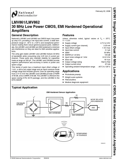
February 22, 2008 LMV861/LMV86230 MHz Low Power CMOS, EMI Hardened Operational AmplifiersGeneral DescriptionNational’s LMV861 and LMV862 are CMOS input, low power op amp IC's, providing a low input bias current, a wide tem-perature range of −40°C to +125°C and exceptional perfor-mance making them robust general purpose parts. Addition-ally, the LMV861 and LMV862 are EMI hardened to minimize any interference so they are ideal for EMI sensitive applica-tions.The unity gain stable LMV861 and LMV862 feature 30 MHz of bandwidth while consuming only 2.25 mA of current per channel. These parts also maintain stability for capacitive loads as large as 200 pF. The LMV861 and LMV862 provide superior performance and economy in terms of power and space usage.This family of parts has a maximum input offset voltage of 1 mV, a rail-to-rail output stage and an input common-mode voltage range that includes ground. Over an operating range from 2.7V to 5.5V the LMV861 and LMV862 provide a PSRR of 93 dB, and a CMRR of 93 dB. The LMV861 is offered in the space saving 5-Pin SC70 package, and the LMV862 in the 8-Pin MSOP.FeaturesUnless otherwise noted, typical values at TA= 25°C, V+ = 3.3V■Supply voltage 2.7V to 5.5V ■Supply current (per channel) 2.25 mA ■Input offset voltage 1 mV max ■Input bias current0.1 pA ■GBW30 MHz ■EMIRR at 1.8 GHz105 dB ■Input noise voltage at 1 kHz8 nV/√Hz ■Slew rate18 V/µs ■Output voltage swing Rail-to-Rail ■Output current drive67 mA ■Operating ambient temperature range−40°C to 125°C Applications■Photodiode preamp■Weight scale systems■Filters/buffers■Medical diagnosis equipmentTypical ApplicationEMI Hardened Sensor Application30024001© 2008 National Semiconductor LMV861 Single/ LMV862 Dual 30 MHz Low Power CMOS, EMI Hardened Operational AmplifiersAbsolute Maximum Ratings (Note 1)If Military/Aerospace specified devices are required,please contact the National Semiconductor Sales Office/Distributors for availability and specifications.ESD Tolerance (Note 2) Human Body Model 2 kV Charge-Device Model 1 kV Machine Model 200VV IN Differential± Supply VoltageSupply Voltage (V + – V −)6V Voltage at Input/Output PinsV + +0.4V V − −0.4VStorage Temperature Range −65°C to +150°CJunction Temperature (Note 3)+150°CSoldering InformationInfrared or Convection (20 sec)260°COperating Ratings(Note 1)Temperature Range (Note 3)−40°C to +125°CSupply Voltage (V + – V −)2.7V to 5.5VPackage Thermal Resistance (θJA (Note 3)) 5-Pin SC70302°C/W 8-Pin MSOP217°C/W3.3V Electrical Characteristics(Note 4)Unless otherwise specified, all limits are guaranteed for T A = 25°C, V + = 3.3V, V − = 0V, V CM = V +/2, and R L =10 k Ω to V +/2.Boldface limits apply at the temperature extremes.Symbol ParameterConditionsMin (Note 6)Typ (Note 5)Max (Note 6)UnitsV OS Input Offset Voltage (Note 9)±273±10001260μV TCV OS Input Offset Voltage Drift (Notes 9, 10) ±0.7±2.6μV/°C I B Input Bias Current (Note 10)0.110500pA I OS Input Offset Current1 pA CMRR Common Mode Rejection Ratio (Note 9)0.2V ≤ V CM ≤ V + - 1.2V 777593 dB PSRR Power Supply Rejection Ratio (Note 9)2.7V ≤ V + ≤ 5.5V,V OUT = 1V777693 dBEMIRREMI Rejection Ratio, IN+ and IN−(Note 8)V RF_PEAK = 100 mV P (−20 dBV P ),f = 400 MHz70 dB V RF_PEAK = 100 mV P (−20 dBV P ),f = 900 MHz80 V RF_PEAK = 100 mV P (−20 dBV P ),f = 1800 MHz105 V RF_PEAK = 100 mV P (−20 dBV P ),f = 2400 MHz110 CMVR Input Common-Mode Voltage Range CMRR ≥ 65 dB −0.1 2.1V A VOLLarge Signal Voltage Gain (Note 11)R L = 2 k ΩV OUT = 0.15V to 1.65V,V OUT = 3.15V to 1.65V 10097110dBR L = 10 k ΩV OUT = 0.1V to 1.65V,V OUT = 3.2V to 1.65V10098113V OOutput Swing High,(measured from V +)R L = 2 k Ω to V +/2 121418mVR L = 10 k Ω to V +/2345Output Swing Low,(measured from V −)R L = 2 k Ω to V +/2 81216mVR L = 10 k Ω to V +/2245 2L M V 861 S i n g l e / L M V 862 D u a lSymbol Parameter Conditions Min(Note 6)Typ(Note 5)Max(Note 6)UnitsI O Output Short Circuit Current Sourcing, VOUT= VCM,VIN= 100 mV615270mASinking, VOUT= VCM,VIN= −100 mV725886ISSupply Current LMV861 2.25 2.593.00mALMV862 4.4SR Slew Rate (Note 7)AV = +1, VOUT= 1 VPP,10% to 90%18V/μs GBW Gain Bandwidth Product30MHz Φm Phase Margin70dege n Input-Referred Voltage Noisef = 1 kHz8nV/f = 100 kHz5inInput-Referred Current Noise f = 1 kHz0.015pA/ROUTClosed Loop Output Impedance f = 20 MHz80ΩC IN Common-Mode Input Capacitance21pF Differential-Mode Input Capacitance15THD Total Harmonic Distortion f = 1 kHz, AV= 1, BW ≥ 500 kHz0.02% 5V Electrical Characteristics (Note 4)Unless otherwise specified, all limits are guaranteed for T = 25°C, V+ = 5V, V− = 0V, VCM = V+/2, and RL=10 kΩ to V+/2. Bold-face limits apply at the temperature extremes.Symbol Parameter Conditions Min(Note 6)Typ(Note 5)Max(Note 6)UnitsVOSInput Offset Voltage(Note 9)±273±10001260μVTCVOSInput Offset Voltage Drift(Notes 9, 10)±0.7±2.6μV/°CIBInput Bias Current(Note 10)0.110500pAIOSInput Offset Current1pACMRR Common-Mode Rejection Ratio(Note 9)0V ≤ V CM ≤ V+ –1.2V787794dBPSRR Power Supply Rejection Ratio(Note 9)2.7V ≤ V+≤ 5.5V,VOUT= 1V777693dBEMIRR EMI Rejection Ratio, IN+ and IN−(Note 8)VRF_PEAK= 100 mVP(−20 dBVP),f = 400 MHz70dB VRF_PEAK= 100 mVP(−20 dBVP),f = 900 MHz80VRF_PEAK= 100 mVP(−20 dBVP),f = 1800 MHz105VRF_PEAK= 100 mVP(−20 dBVP),f = 2400 MHz110CMVR Input Common-Mode Voltage Range CMRR ≥ 65 dB−0.1 3.9VAVOLLarge Signal Voltage Gain(Note 11)RL= 2 kΩVOUT= 0.15V to 2.5V,VOUT= 4.85V to 2.5V103100111dBRL= 10 kΩVOUT= 0.1V to 2.5V,VOUT= 4.9V to 2.5V103100113LMV861 Single/ LMV862 DualSymbol ParameterConditionsMin (Note 6)Typ (Note 5)Max (Note 6)UnitsV OOutput Swing High,(measured from V +)R L = 2 k Ω to V +/2 131519mVR L = 10 k Ω to V +/2345Output Swing Low,(measured from V −)R L = 2 k Ω to V +/2 101418mVR L = 10 k Ω to V +/2345I OOutput Short Circuit CurrentSourcing, V OUT = V CM ,V IN = 100 mV 9086150 mA Sinking, V OUT = V CM ,V IN = −100 mV9086150 I SSupply CurrentLMV861 2.47 2.843.27mALMV8624.9 SR Slew Rate (Note 7)A V = +1, V OUT = 2V PP ,10% to 90%20 V/μs GBW Gain Bandwidth Product31 MHz Φm Phase Margin71 deg e n Input-Referred Voltage Noise f = 1 kHz 8 nV/f = 100 kHz 5 i n Input-Referred Current Noise f = 1 kHz0.015 pA/R OUT Closed Loop Output Impedance f = 20 MHz 60 ΩC IN Common-Mode Input Capacitance 20 pF Differential-Mode Input Capacitance15 THDTotal Harmonic Distortionf = 1 kHz, A V = 1, BW ≥ 500 kHz0.02%Note 1:Absolute Maximum Ratings indicate limits beyond which damage to the device may occur. Operating Ratings indicate conditions for which the device is intended to be functional, but specific performance is not guaranteed. For guaranteed specifications and the test conditions, see the Electrical Characteristics Tables.Note 2:Human Body Model, applicable std. MIL-STD-883, Method 3015.7. Machine Model, applicable std. JESD22-A115-A (ESD MM std. of JEDEC) Field-Induced Charge-Device Model, applicable std. JESD22-C101-C (ESD FICDM std. of JEDEC).Note 3:The maximum power dissipation is a function of T J(MAX), θJA , and T A . The maximum allowable power dissipation at any ambient temperature is P D = (T J(MAX) - T A )/ θJA . All numbers apply for packages soldered directly onto a PC board.Note 4:Electrical table values apply only for factory testing conditions at the temperature indicated. Factory testing conditions result in very limited self-heating of the device.Note 5:Typical values represent the most likely parametric norm as determined at the time of characterization. Actual typical values may vary over time and will also depend on the application and configuration. The typical values are not tested and are not guaranteed on shipped production material.Note 6:Limits are 100% production tested at 25°C. Limits over the operating temperature range are guaranteed through correlations using statistical quality control (SQC) method.Note 7:Number specified is the slower of positive and negative slew rates.Note 8:The EMI Rejection Ratio is defined as EMIRR = 20log ( V RF_PEAK /ΔV OS ).Note 9:The typical value is calculated by applying absolute value transform to the distribution, then taking the statistical average of the resulting distribution Note 10:This parameter is guaranteed by design and/or characterization and is not tested in production.Note 11:The specified limits represent the lower of the measured values for each output range condition. 4L M V 861 S i n g l e / L M V 862 D u a lConnection Diagrams5-Pin SC7030024002Top View8-Pin MSOP30024003Top ViewOrdering InformationPackage Part Number Package MarkingTransport Media NSC Drawing Status 5-Pin SC70LMV861MG AEA 1k units Tape and Reel MAA05A Release LMV861MGX 3k units Tape and Reel 8-Pin MSOPLMV862MM AJ5A1k units Tape and Reel MUA08APreliminaryLMV862MMX3.5k units Tape and ReelLMV861 Single/ LMV862 DualTypical Performance CharacteristicsAt T A = 25°C. R L = 10 k Ω, V + = 3.3V, V − = 0V, unless otherwisespecified.V OS vs. V CM at V + = 3.3V30024010V OS vs. V CM at V + = 5.0V30024011V OS vs. Supply Voltage 30024012V OS vs. Temperature30024013V OS vs. V OUT 30024014Input Bias Current vs. V CM at 25°C30024015 6L M V 861 S i n g l e / L M V 862 D u a lInput Bias Current vs. VCMat 85°C30024016Input Bias Current vs. VCMat 125°C30024017Supply Current vs. Supply Voltage Single LMV86130024018Supply Current vs. Supply Voltage Dual LMV86230024019Supply Current vs. Temperature Single LMV86130024021Supply Current vs. Temperature Dual LMV86230024022LMV861 Single/ LMV862 DualSinking Current vs. Supply Voltage30024024Sourcing Current vs. Supply Voltage30024025Output Swing High vs. Supply Voltage R L = 2 k Ω30024026Output Swing High vs. Supply Voltage R L = 10 k Ω30024027Output Swing Low vs. Supply Voltage R L = 2 k Ω30024028Output Swing Low vs. Supply Voltage R L = 10 k Ω30024029 8L M V 861 S i n g l e / L M V 862 D u a lOutput Voltage Swing vs. Load Current at V+ = 3.3V30024030Output Voltage Swing vs. Load Current at V+ = 5.0V30024031Open Loop Frequency Response vs. Temperature30024032Open Loop Frequency Response vs. Load Conditions30024033Phase Margin vs. Capacitive Load30024034PSRR vs. Frequency30024035LMV861 Single/ LMV862 DualCMRR vs. Frequency30024036Channel Separation vs. Frequency30024037Large Signal Step Response with Gain = 130024038Large Signal Step Response with Gain = 1030024039Small Signal Step Response with Gain = 130024040Small Signal Step Response with Gain = 1030024041 10L M V 861 S i n g l e / L M V 862 D u a lSlew Rate vs. Supply Voltage30024042Input Voltage Noise vs. Frequency30024044THD+N vs. Frequency30024045THD+N vs. Amplitude30024046ROUTvs. Frequency30024047EMIRR IN+ vs. Power at 400 MHz30024048LMV861 Single/ LMV862 DualEMIRR IN+ vs. Power at 900 MHz30024049EMIRR IN+ vs. Power at 1800 MHz30024050EMIRR IN+ vs. Power at 2400 MHz 30024051EMIRR IN+ vs. Frequency30024052 12L M V 861 S i n g l e / L M V 862 D u a lApplication InformationINTRODUCTIONThe LMV861 and LMV862 are operational amplifiers with ex-cellent specifications, such as low offset, low noise and a rail-to-rail output. These specifications make the LMV861 and LMV862 great choices for medical and instrumentation appli-cations such as diagnosis equipment and power line moni-tors. The low supply current is perfect for battery powered equipment. The small packages, SC70 package for the LMV861, and the MSOP package for the dual LMV862, make these parts a perfect choice for portable electronics. Addi-tionally, the EMI hardening makes the LMV861 and LMV862a must for almost all op amp applications. Most applications are exposed to Radio Frequency (RF) signals such as the signals transmitted by mobile phones or wireless computer peripherals. The LMV861 and LMV862 will effectively reduce disturbances caused by RF signals to a level that will be hard-ly noticeable. This again reduces the need for additional filtering and shielding. Using this EMI resistant series of op amps will thus reduce the number of components and space needed for applications that are affected by EMI, and will help applications, not yet identified as possible EMI sensitive, to be more robust for EMI.INPUT CHARACTERISTICSThe input common mode voltage range of the LMV861 and LMV862 includes ground, and can even sense well below ground. The CMRR level does not degrade for input levels up to 1.2V below the supply voltage. For a supply voltage of 5V,the maximum voltage that should be applied to the input for best CMRR performance is thus 3.8V.When not configured as unity gain, this input limitation will usually not degrade the effective signal range. The output is rail-to-rail and therefore will introduce no limitations to the signal range.The typical offset is only 0.273 mV, and the TCV OS is 0.7 μV/°C, specifications close to precision op amps.CMRR MEASUREMENTThe CMRR measurement results may need some clarifica-tion. This is because different setups are used to measure the AC CMRR and the DC CMRR.The DC CMRR is derived from ΔV OS versus ΔV CM . This value is stated in the tables, and is tested during production testing.The AC CMRR is measured with the test circuit shown in Figure 1.30024064FIGURE 1. AC CMRR Measurement SetupThe configuration is largely the usually applied balanced con-figuration. With potentiometer P1, the balance can be tuned to compensate for the DC offset in the DUT. The main differ-ence is the addition of the buffer. This buffer prevents the open-loop output impedance of the DUT from affecting the balance of the feedback network. Now the closed-loop output impedance of the buffer is a part of the balance. But as the closed-loop output impedance is much lower, and by careful selection of the buffer also has a larger bandwidth, the total effect is that the CMRR of the DUT can be measured much more accurately. The differences are apparent in the larger measured bandwidth of the AC CMRR.One artifact from this test circuit is that the low frequency CM-RR results appear higher than expected. This is because in the AC CMRR test circuit the potentiometer is used to com-pensate for the DC mismatches. So, mainly AC mismatch is all that remains. Therefore, the obtained DC CMRR from this AC CMRR test circuit tends to be higher than the actual DC CMRR based on DC measurements.The CMRR curve in Figure 2 shows a combination of the AC CMRR and the DC CMRR.30024036FIGURE 2. CMRR CurveLMV861 Single/ LMV862 DualOUTPUT CHARACTERISTICSAs already mentioned the output is rail-to-rail. When loadingthe output with a 10 kΩ resistor the maximum swing of theoutput is typically 3 mV from the positive and negative rail.The output of the LMV861 and LMV862 can drive currents upto 70 mA at 3.3V, and even up to 150 mA at 5V.The LMV861 and LMV862 can be connected as non-invertingunity gain amplifiers. This configuration is the most sensitiveto capacitive loading. The combination of a capacitive loadplaced at the output of an amplifier along with the amplifier’soutput impedance creates a phase lag, which reduces thephase margin of the amplifier. If the phase margin is signifi-cantly reduced, the response will be under damped whichcauses peaking in the transfer and, when there is too muchpeaking, the op amp might start oscillating. The LMV861 andLMV862 can directly drive capacitive loads up to 200 pF with-out any stability issues. In order to drive heavier capacitiveloads, an isolation resistor, RISO, should be used, as shownin Figure 3. By using this isolation resistor, the capacitive loadis isolated from the amplifier’s output, and hence, the polecaused by CLis no longer in the feedback loop. The larger thevalue of RISO, the more stable the amplifier will be. If the valueof RISOis sufficiently large, the feedback loop will be stable,independent of the value of CL. However, larger values ofRISOresult in reduced output swing and reduced output cur-rent drive.30024063FIGURE 3. Isolating Capacitive LoadA resistor value of around 50Ω would be sufficient. As an ex-ample some values are given in the following table, for 5V andan open loop gain of 111 dB.CLOADRISO300 pF62Ω400 pF55Ω500 pF50ΩWhen increasing the closed-loop gain the capacitive load canbe increased even further. With a closed loop gain of 2 and a27Ω isolation resistor, the load can be 1 nFEMIRRWith the increase of RF transmitting devices in the world, theelectromagnetic interference (EMI) between those devicesand other equipment becomes a bigger challenge. TheLMV861 and LMV862 are EMI hardened op amps which arespecifically designed to overcome electromagnetic interfer-ence. Along with EMI hardened op amps, the EMIRR param-eter is introduced to unambiguously specify the EMI perfor-mance of an op amp. This section presents an overview ofEMIRR. A detailed description on this specification for EMIhardened op amps can be found in Application Note AN-1698.The dimensions of an op amp IC are relatively small com-pared to the wavelength of the disturbing RF signals. As aresult the op amp itself will hardly receive any disturbances.The RF signals interfering with the op amp are dominantlyreceived by the PCB and wiring connected to the op amp. Asa result the RF signals on the pins of the op amp can be rep-resented by voltages and currents. This representation sig-nificantly simplifies the unambiguous measurement andspecification of the EMI performance of an op amp.RF signals interfere with op amps via the non-linearity of theop amp circuitry. This non-linearity results in the detection ofthe so called out-of-band signals. The obtained effect is thatthe amplitude modulation of the out-of-band signal is down-converted into the base band. This base band can easilyoverlap with the band of the op amp circuit. As an exampleFigure 4 depicts a typical output signal of a unity-gain con-nected op amp in the presence of an interfering RF signal.Clearly the output voltage varies in the rhythm of the on-offkeying of the RF carrier.30024065FIGURE 4. Offset voltage variation due to an interferingRF signalEMIRR DEFINITIONTo identify EMI hardened op amps, a parameter is neededthat quantitatively describes the EM performance of opamps. A quantitative measure enables the comparison andthe ranking of op amps on their EMI robustness. Thereforethe EMI Rejection Ratio (EMIRR) is introduced. This param-eter describes the resulting input-referred offset voltage shiftof an op amp as a result of an applied RF carrier (interference)with a certain frequency and level. The definition of EMIRR isgiven by:In which VRF_PEAKis the amplitude of the applied un-modu-lated RF signal (V) and ΔVOSis the resulting input-referredoffset voltage shift (V). The offset voltage depends quadrati-cally on the applied RF level, and therefore, the RF level atwhich the EMI RR is determined should be specified. Thestandard level for the RF signal is 100 mVP. Application NoteAN-1698 addresses the conversion of an EMIRR measuredfor an other signal level than 100 mVP. The interpretation ofthe EMIRR parameter is straightforward. When two op ampshave EMIRRs which differ by 20 dB, the resulting error signalswhen used in identical configurations, differs by 20 dB as well.So, the higher the EMIRR, the more robust the op amp.Coupling an RF Signal to the IN+ PinEach of the op amp pins can be tested separately on EMIRR.n this section the measurements on the I N+ pin (which,based on symmetry considerations, also apply to the IN- pin)are discussed. In Application Note AN-1698 the other pins ofthe op amp are treated as well. For testing the IN+ pin the op 14LMV861Single/LMV862Dualamp is connected in the unity gain configuration. Applying the RF signal is straightforward as it can be connected directly to the IN+ pin. As a result the RF signal path has a minimum of components that might affect the RF signal level at the pin. The circuit diagram is shown in Figure 5. The PCB trace fromRFIN to the IN+ pin should be a 50Ω stripline in order to matchthe RF impedance of the cabling and the RF generator. On the PCB a 50Ω termination is used. This 50Ω resistor is also used to set the bias level of the IN+ pin to ground level. For determining the EMIRR, two measurements are needed: one is measuring the DC output level when the RF signal is off; and the other is measuring the DC output level when the RF signal is switched on. The difference of the two DC levels is the output voltage shift as a result of the RF signal. As the op amp is in the unity gain configuration, the input referred offset voltage shift corresponds one-to-one to the measured output voltage shift.30024067 FIGURE 5. Circuit for coupling the RF signal to IN+Cell Phone CallThe effect of electromagnetic interference is demonstrated in a setup where a cell phone interferes with a pressure sensor application. The application is show in Figure 7.This application needs two op amps and therefore a dual op amp is used. The op amp configured as a buffer and con-nected at the negative output of the pressure sensor prevents the loading of the bridge by resistor R2. The buffer also pre-vents the resistors of the sensor from affecting the gain of the following gain stage. The op amps are placed in a single sup-ply configuration.The experiment is performed on two different op amps: a typ-ical standard op amp and the LMV862, EMI hardened dual op amp. A cell phone is placed on a fixed position a couple of centimeters from the op amps in the sensor circuit.When the cell phone is called, the PCB and wiring connected to the op amps receive the RF signal. Subsequently, the op amps detect the RF voltages and currents that end up at their pins. The resulting effect on the output of the second op amp is shown in Figure 6.30024062FIGURE 6. Comparing EMI RobustnessThe difference between the two types of op amps is clearly visible. The typical standard dual op amp has an output shift (disturbed signal) larger than 1V as a result of the RF signal transmitted by the cell phone. The LMV862, EMI hardened op amp does not show any significant disturbances. This means that the RF signal will not disturb the signal entering the ADC when using the LMV862.30024061FIGURE 7. Pressure Sensor Application LMV861 Single/ LMV862 DualDECOUPLING AND LAYOUTCare must be given when creating a board layout for the op amp. For decoupling the supply lines it is suggested that 10 nF capacitors be placed as close as possible to the op amp. For single supply, place a capacitor between V + and V −. For dual supplies, place one capacitor between V + and the board ground, and a second capacitor between ground and V −.Even with the LMV861 and LMV862 inherent hardening against EMI, it is still recommended to keep the input traces short and as far as possible from RF sources. Then the RF signals entering the chip are as low as possible, and the re-maining EMI can be, almost, completely eliminated in the chip by the EMI reducing features of the LMV861 and LMV862.LOAD CELL SENSOR APPLICATIONThe LMV861 and LMV862 can be used for weight measuring system applications which use a load cell sensor. Examples of such systems are: bathroom weight scales, industrial weight scales and weight measurement devices on moving equipment such as forklift trucks.The following example describes a typical load cell sensor application that can be used as a starting point for many dif-ferent types of sensors and applications. Applications in en-vironments where EMI may appear would especially benefit from the EMIRR performance of the LMV861 and LMV862.Load Cell CharacteristicsThe load cell used in this example is a Wheatstone bridge.The value of the resistors in the bridge changes when pres-sure is applied to the sensor. This change of the resistor values will result in a differential output voltage depending on the sensitivity of the sensor, the used supply voltage and the applied pressure. The difference between the output at full scale pressure and the output at zero pressure is defined as the span of the load cell. A typical value for the span is 10 mV/V.The circuit configuration should be chosen such that loading of the sensor is prevented. Loading of the resistor bridge due to the circuit following the sensor, could result in incorrect output voltages of the sensor.Load Cell ExampleFigure 8 shows a typical schematic for a load cell application.It uses a single supply and has an adjustment for both positive and negative offset of the load cell. An ADC converts the am-plified signal to a digital signal.The op amps A1 and A2 are configured as buffers, and are connected at both the positive and the negative output of the load cell. This is to prevent the loading of the resistor bridge in the sensor by the resistors configuring the differential op amp circuit (op amp A4). The buffers also prevent the resis-tors of the sensor from affecting the gain of the following gain stage. The third buffer (A3) is used to create a reference volt-age, to correct for the offset in the system.Given the differential output voltage V S of the load cell, the output signal of this op amp configuration, V OUT , equals:To align the pressure range with the full range of an ADC the correct gain needs to be set. To calculate the correct gain, the power supply voltage and the span of the load cell are need-ed. For this example a power supply of 5V is used and the span of the sensor, in this case a 125 kg sensor, is 100 mV.With the configuration as shown in Figure 8, this signal is covering almost the full input range of the ADC. With no weight on the load cell, the output of the sensor and the op amp A4 will be close to 0V. With the full weight on the load cell, the output of the sensor is 100 mV, and will be amplified with the gain from the configuration. In the case of the con-figuration of Figure 8 the gain is R3 / R1 = 51 k Ω / 100Ω = 50.This will result in a maximum output of 100 mV x 50 = 5V,which covers the full range of the ADC.For further processing the digital signal can be processed by a microprocessor following the ADC, this can be used to dis-play or log the weight on the load cell. To get a resolution of 0.5 kg, the LSB of the ADC should be smaller then 0.5 kg /125 kg = 1/1000. A 12-bit ADC would be sufficient as this gives 4096 steps. A 12-bit ADC such as the two channel 12-bit ADC122S021 can be used for this application.30024069FIGURE 8. Load Cell Application 16L M V 861 S i n g l e / L M V 862 D u a l。

警告 (3)播放器外形和控制键 (5)附件 (8)安装电池 (9)液晶显示屏 (10)欣赏音乐 (11)语音录音 (13)模式按钮 (14)使用均衡器 (15)重放文件 (17)将软件安装到计算机 (19)MX 8610 Manager安装步骤 (20)将MP3播放器连接到计算机 (23)格式化内置内存 (24)将附加字体下载到MP3播放器中 (26)删除MP3播放器中的字体 (28)将文件传送到MP3播放器 (30)删除文件(在MP3播放器上) (33)删除文件(在计算机上) (34)设置重放顺序 (36)插入MMC和SD卡 (39)退出MMC和SD卡 (40)安全指南 (41)故障诊断 (42)产品技术规格 (43)- 1 -- 2 -为了避免失火与触电危险,请不要将播放器暴露在雨中或湿气中。
注意:为了避免触电危险,不要打开盖(或背面)。
机器内部无用户自己可以修理的零件。
如需修理,应由专业服务人员进行。
机器底板或背面的图形标记的含意如下。
等边三角形内的带箭头的闪电符号是用于提醒用户,产品外壳内有未绝缘的电压。
这个电压的幅度足以使人员触电。
等边三角形内的惊叹号用于提醒用户,部件上的文字说明是用于操作和维护(维修)的重要规则。
为了避免触电不要打开机匣。
仅专业人员可以维修。
注意如超出本手册的规定,对产品进行控制、调整或使用会导致有害的无线电辐射。
注意 有触电的危险不要打开耳机插孔锁定键音量调整麦克风录音(录语音)模式(快进/ 快退)(均衡器:X-LIVE/JAZZ/ROAK/FLA T/RETURN)(重复:简介/重复当前曲目/重复全部曲目/随机播放曲目/正常播放/返回)(删除:删除文件/返回)(存储器信息)(背光)开机/播放/暂停/关机液晶显示屏- 3 -电池盖和SD卡插槽插槽- 4 -- 5 -开机 - 按功能键(如果选择了“Hold (锁定)”键,按下“Fun ”键将没有作用!)播放-按一次功能键 暂停-按一次功能键 快进-按两次功能键 快倒-按三次功能键停止-按一次“Stop ”键 开机关机-按停止键,直到屏幕没有显示。
R EV. Pr0 9/27/01Information furnished by Analog Devices is believed to be accurate and reliable. However, no responsibility is assumed by Analog Devices for its use, nor for any infringements of patents or other rights of third parties which may result from its use. No license is granted by implication or otherwise under any patent or patent rights of Analog Dev ices. O n e T e c h n o l o g y W a y,P O B o x9106,N o r w o o d,M A02062-9106, USATel: 617/329-4700World Wide Web Site: Fax: 617/326-8703© Analog Devices, Inc., 1997a Precision Very Low NoiseLow Input Bias CurrentWide Bandwidth JFETOperational Amplifiers P r e l i m i n a r y Technical Data AD8610 FEATURESLow noise: 6nV/√HzLow Offset Voltage: 100µV max.Low input Bias current 10pA max.Fast settling: 600ns to 0.01%Low DistortionUnity Gain StableNo Phase ReversalDual supply operation: ±5V to ±13VAPPLICATIONSPhotodiode AmplifierATEInstrumentationSensors and ControlsPrecision filtersHigh Fidelity AudioGENERAL DESCRIPTIONThe AD8610 is a precision JFET input amplifier featuring very low offset voltage and drift, very low input voltage and current noise, very low input bias current and wide bandwidth. Outputs are stable with capacitive loads of over 500pF in non-inverting unity gain. Output swings to within 1.2V of the supplies even with a 1kohm load, maximizing dynamic range with limited supply voltages.Applications for these amplifiers include electronic instruments, ATE front-end amplification and integrator circuits, CAT/MRI/Ultrasound medical instrumentation, photodiode amplification, fast precision filters and professional quality audio. The AD8610 is specified over the extended industrial (-40° to +125°C) temperature range. The AD8610 is available in the 8-lead SOIC and the tiny MSOP8 surface mount packages. MSOP8 packaged devices are available only in Tape-and-Reel.Output Short-Circuit Duration..........................................Indefinite Storage Temperature RangeR, RM Package...............................................-65°C to +150°C Operating Temperature RangeAD8610............................................................-40°C to +85°C Junction Temperature RangeR, RM Package...............................................-65°C to +150°C Lead Temperature Range (Soldering, 60 Sec)........................+300°C NOTES1 Absolute maximum ratings apply at 25°C, unless otherwise noted.2 θJA is specified for the worst case conditions, i.e., θJA is specified for device soldered in circuit board for surface mount packages.ORDERING GUIDEModel Temperature Range Package Description Package Option AD8610ARM -40°C to +125°C 8-Pin MSOP RM-8AD8610AR -40°C to +125°C 8-Pin SOIC R-8AD8610BR -40°C to +125°C 8-Pin SOIC R-8。
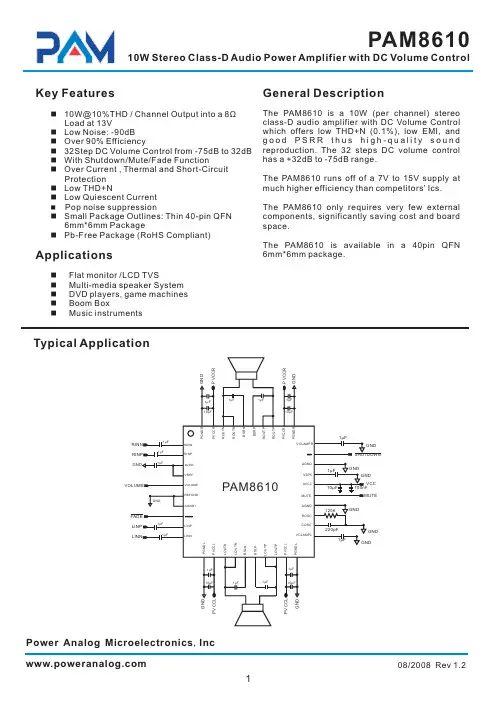
PAM8301中文资料Key FeaturesApplications1.5W Output at 10%THD with a 8Loadand 5V Power SupplyFilterless,Low Quiescent Current and LowEMIHigh Efficiency up to 88%Superior Low Noise Short Circuit Protection Thermal ShutdownFew External Components to Save Spaceand CostTiny SOT23-6Package PMP/MP4GPSPortable Speakers Walkie TalkieHandsfree phones/Speaker Phones Cellular Phonesdirectly system cost It can optimize battery life thus is ideal for portable applications.Ωn n n n n nGeneral DescriptionThe PAM8301is a 1.5W class-D mono audio amplifier.Its low THD+N feature offers high-quality sound reproduction.The new filterless architecture allows the device to drive speaker instead of using low-pass output filters,therefore save and PCB area.With the same number of external components,the efficiency of the PAM8301is much better than that of class-AB cousins.The PAM8301is available in SOT23-6package.n n n n n n n n n Pb-Free PackageTypical ApplicationShutdownAudioBlock DiagramPin Configuration &Marking InformationTOP VIEW SOT23-6654123FPXYWFP:Product Code of PAM8301X:Internal Code Y:Year W:WeekINSD-OUT+OUT GNDVDDAbsolute Maximum RatingsThese are stress ratings only and functional operation is not implied Exposure to absolute maximum ratings for prolonged time periods may affect device reliability All voltages are with respect to ground ...Supply Voltage at no Input Signal...................6.6V Storage Temperature.....................-65to 150Soldering Temperature......................Input Voltage.............................-0.3V to V +0.3VMaximum Junction Temperature..................150°C °C °C 300°C,5secDD Recommended Operating ConditionsSupply voltage Range........................Operation Temperature Range........-40to 85Junction Temperature Range.........-40to 1252.5V to 5.5V Max.Supply Voltage (for Max.duration of30minutes)................................................6.0V°C °C °C °CThermal InformationElectrical CharacteristicV =5V,Gain =24dB,R =8T =25unless otherwise noted. DD L A Ω,,°CTypical Performance CharacteristicT =25°C,unless otherwise noted.A 3.Efficiency VS Output Power5.THD+N VS Output Power60%65%70%75%80%85%90%95%100%020040060080010001200Output Pow er(m W)E f f i c i e n c y000%20m350m 100m 200m500m 12W% 050100150200250300350020406080100120140T em p eratu reF r e q u e n c y (k H z )1.Frequency VS Supply Voltage2.Frequency VS Temperature 238 240242244246248250252 25425625823456Supply Voltage (V)F r e q u e n c y (k H z )4.Efficiency VS Output Power 6.THD+N VS Output Power20m350m 100m 200m500m 12W50%55%60%65%70%75%80%85%90%200400600800100012001400160018002000Output P ow er (m W)E f f i c i e n c yTypical Performance Characteristic T =25°C,unless otherwise noted.A 7.THD+N VS Frequency2020k501002005001k2k5k10kHz11.Frequency Response12.Noise Floord BV 2020k501002005001k 2k 5k 10k Hz %2020k501002005001k 2k 5k 10k Hz8.THD+N VS Frequency9.THD+N VS Frequency10.THD+N VS Frequency2020k501002005001k 2k 5k 10k Hz+++++++++d B r A2020k501002005001k 2k 5k 10k Hz%2020k501002005001k 2k 5k 10k HzTypical Performance CharacteristicT =25°C unless otherwise noted.A 13.PSRR14.EMI vs Frequency.-+0---------d B2010k501002005001k 2k 5k HzR =8L Ω,Gain=23dB,V =5V,Po=500DD mW Test Setup for Performance Testing1.The AP AUX-0025low pass filter is necessary for every class-D amplifier measurement with AP analyzer.2.Two 22μH inductors are used in series with load resistor to emulate the small speaker for efficiency measurement.PAM8301Demo BoardApplication InformationMaximum GainAs shown in block diagram (page 2),the PAM8301has two internal amplifier stages.The first stage's gain is externally configurable,while the second stage's is internally fixed.The closed-loop gain of the first stage is set by selecting the ratio of R to R while the second stage's gain is fixed at 2x.The output of amplifier 1serves as the input to amplifier 2,thus the two amplifiers produce signals identical in magnitude,but different in phase by 180°.Consequently,the differential gain for the IC isA =20*log [2*(R /R )]The PAM8301sets maximum R =80k ,minimum R =10k ,so the maximum closed-gain is 24dB.f i VD f i f i ΩΩInput Capacitors (Ci)Power Supply Decoupling (Cs)Shutdown OperationFor the best power on/off pop performance,the amplifier should be set in the shutdown mode prior to power on/off operation.Under Voltage Lock-out (UVLO)In typical application,an input capacitor,Ci,is required to allow the amplifier to bias input signals to a proper DC level for optimum operation.In this case,Ci and the minimum input impedance Ri (10k internal)form a high pass filter with a corner frequency determined by the following equation:It is important to choose the value of Ci as it directly affectslow frequency performance of the circuit,for example,when an application requires a flat bass response as low as 100Hz.Equation is reconfigured as follows:As the input resistance is variable,for the Ci value of 0.16F,one should actually choose the Ci within the range of 0.1F to 0.22 F.A further consideration for this capacitor is the leakage path from the input source through the input network (Ri,RF,Ci)to the load.This leakage current creates a DC offset voltage at the input to the amplifier that reduces useful headroom,especially in high gain application.For this reason,a low leakage tantalum or ceramiccapacitor is the best choice.When a polarized capacitor is used,the positive side of the capacitor should face the amplifier input in most applications as the DC level is held at VDD/2,which is likely higher than the source DC level.Please note that it is important to confirm the capacitor polarity in the application.The PAM8301is a high-performance CMOS audio amplifier that requires adequate power supply decoupling to ensure the output THD and PSRR as low as possible.Power supply decoupling affects low frequency response.Optimum decoupling is achieved by using two capacitors of different types that target different types of noise on the power supply leads.For higher frequency transients,spikes,or digital hash on the line,a good low equivalent-series-resistance (ESR)ceramic capacitor,typically 1.0μF is good,placing it as close as possible to the device VDD terminal.For filtering lower-frequency noise signals,a capacitor of 10μF orlarger,closely located to near the audio power amplifier is recommended.In order to reduce shutdown power consumption,the PAM8301contains shutdown circuitry for turnoff the amplifier.This shutdown feature turns the amplifier off when a logic low is applied on the SHDOWN pin.By switching the shutdown pin over to GND,the PAM8301supply current draw will be minimized in idle mode.The PAM8301incorporates circuitry to detect low on or off voltage.When the supply voltage drops to 2.1V or below,the PAM8301goes into a state of shutdown,and the device comes out of its shutdown state and starts to normal operation by reset the power supply or pin.μμμSD ()C 1f 2RiCi p =()i c 1Ci 2R f p =How to Reduce EMI (Electro Magnetic Interference)A simple solution is to put an additional capacitor 1000F at power supply terminal for power line coupling if the traces from amplifier to speakers are short (<20cm).Most applications require a ferrite bead filter as shown at Figure 1.The ferrite filter depresses EMI of around 1MHz and higher.When selecting a ferrite bead,choose one with high impedance at high frequencies and low impedance at low frequencies.Figure 1:Ferrite Bead Filter to Reduce EMIμOrdering InformationPAM8301Pin ConfigurationNumber of pins Pin TypeSOT23-6Outline DimensionsGAUGE PLANE SEATING PLANE PLANTINGBASE SECTION A-ASEE VIEWSUnit:Millimeter。
DIY使⽤51单⽚机控制的PAM861010W10W数字功放我爱单⽚机今天天⽓不错,⼜刮风⼜下⾬的。
据说适合发帖。
楼主是⼀个⾳响“爱好者”,从2822开始,2025,2003,2030陆续都做了⼀遍。
但是⼀直没有玩过传说中的数字功放。
⾃从论坛上推出PAM8610的数字功放板后,⼼就痒痒了。
⼀直想弄⼀⽚玩玩,坛⼦⼜正好举办单⽚机⽐赛,就想着做⼀个数字⾳量控制的数字功放参个赛。
数字功放嘛,⾳量还⽤电位器调节就有点OUT了。
攒够MM,去淘园兑换的时候却发现⽊有货了,只有那种集成了MP3解码的功放板,但这不是我想要的。
不能就这么放弃了吧,怎么办?幸好我们有万能的X宝,很容易就找到了这货,28元⼀⽚。
顺便买了⼀些乱七⼋遭的东东平衡⼀下运费。
本次DIY前后⼤概⽤了有⼀个⽉,过程是有点漫长的。
但是作为⼀名⾮专业的中年男⼈,有太多做不完的正经事情。
折腾这货只能利⽤晚上的空闲时间,熬夜是很正常滴,但是DIY的过程还是挺享受的。
先贴上⼀段视频,感兴趣的再往下看⼀、⼯欲善其事,必先美其壳⼀件DIY“作品”,电路做的再优秀,但是如果没有⼀个合适的外壳的话,效果也会⼤打折扣的。
外壳本来也是想买成品的,发现价格动辄上百,不符合DIY的精神。
于是找到⼀个有些年头的⼩壳⼦,⽐划⼀下发现⼤⼩也很合适。
就是太破旧了,不过这点⼩问题难不倒本“DIY达⼈”。
先⽤砂纸磨啊磨⽼产品就是厚道,这么厚的壳⼦现在还有吗?但是对于只有⼀只⼿电钻作为开孔设备的楼主来说,这绝对不是⼀件幸福的事。
我钻,我钻,我再钻……(其中断掉钻头N⽀)开孔后打磨好的样⼦⾃喷漆上阵,我喷……为了节约时间,“烤漆”中……喷好漆后的样⼦,⼀共喷了4~6遍,看起来挺光亮的。
最后涂了⼀遍清漆保护⼀下⽂件夹做的⾯板外壳基本完成⼆、热转印⼤*法+洞洞板混⾎PCB⾯板由于需要准确定位数码管与编码开关的位置,热转印怕搞不定。
⽼办法,OO板上场显⽰部分调试通过电路图腐蚀好的板⼦。

目 录1 安全指导 (1)2 Junior-PAM组件及安装 (2)2.1 Junior-PAM组件 (2)2.2 仪器的组装及软件安装 (3)2.2.1 Junior-PAM组装 (3)2.2.2 安装WinControl-3软件 (3)3 PAM 荧光测定技术和饱和脉冲分析 (4)3.1 调制荧光(脉冲-振幅-调制) (4)3.2 饱和脉冲分析法 (6)4 基本实验 (8)4.1 Fo'-Mode的测量 (8)4.2 荧光诱导曲线 (9)5 Junior-PAM的操作 (11)5.1 初始窗口/主窗口 (11)5.1.1 Box (1)主菜单 (12)5.1.2 Box (2) 数据管理和图形形状的设定 (13)5.1.3 Box (3) 侧栏 (14)5.1.4 Box (4) 饱和脉冲分析数据 (15)5.1.5 Box (5) 在线数据 (16)5.1.6 Box (6) 饱和脉冲触发 (16)5.1.7 Box(7) 实验的参数及程序 (16)5.1.8 Box (8) 图形形状及荧光仪设置 (17)5.1.9 Box (9) 坐标轴调整 (18)5.1.10 选择纵坐标及进行文本注释 (18)5.1.11 图表区-选择数据 (18)5.2 诱导曲线窗口 (19)5.3 光响应曲线 (19)5.4 饱和脉冲图形窗口 (19)5.4.1 Box (2) 数据管理 (19)5.4.2 Box (3) 侧栏 (20)5.4.3 饱和脉冲面板 (20)5.5 报告文件窗口 (21)5.5.1 Box (11) 数据管理 (21)5.5.2 Box (12) 报告数据区域 (22)5.6 设置窗口 (23)5.6.1 Box (14) 设备名 (23)5.6.2 Box (15) 测量相关设置 (23)5.6.3 Box (16) 光源相关设置 (24)5.6.4 Box (17) 程序相关设置 (25)5.6.5 Box (18) 光强列表 (25)5.7 系统设置 (26)6 参数符号及计算公式 (27)6.1 相对荧光产量 (27)6.1.1 样品暗适应后进行测定 (27)6.1.2 对光下样品进行测量 (27)6.2 荧光淬灭参数 (28)6.3 相对电子传递速率(ETR) (29)6.4 光响应曲线 (30)6.5 本章参考文献 (32)7 JUNIOR-PAM 技术参数 (34)8 2007-2008年部分PAM文献 (35)1 安全指导1、仪器安装使用前首先阅读安全指导和操作指南2、注意所有的安全警告3、仪器要远离热源4、仪器应放在通风的环境中5、保持仪器清洁,注意防尘,远离水和潮湿的地方6、只能用干布清洁仪器7、不要自行打开仪器,仪器应由专业人员维修8、不要用光纤对着眼睛以免强光灼伤!!!9、禁止过度弯曲光纤!!!10、每次测量开始前应通过调节“Gain”、测量光光强使只打开测量光时的荧光Ft(即Fo)小于60011、不允许液体或者其它东西进入仪器内部12、仪器使用时请轻拿轻放13、仪器只允许通过USB供电(5V)2 Junior-PAM组件及安装2.1 Junior-PAM组件a) Junior-PAM主机b) USB连接线c)包含WinControl-3软件和英文版操作手册的光盘d) 英文版操作手册e)400×1.5 mm(长×直径)光纤f) 叶夹和磁性叶夹g) 荧光标准图2.1 Junior-PAM的组成2.2 仪器的组装及软件安装2.2.1 Junior-PAM组装¾将光纤较粗的一端插到Junior-PAM主机的光纤接口,轻轻的将光纤插到底,锁紧。