ROS+三层交换机+vlan三层教程
- 格式:docx
- 大小:60.23 KB
- 文档页数:4
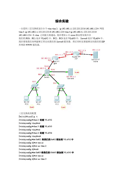
综合实验一台思科三层交换机划分3个vlan vlan 2:ip 192.168.1.1 255.255.255.0 192.168.1.254 网段vlan 3 :ip 192.168.2.1 255.255.255.0 192.168.2.254 vlan 4 ip 192.168.3.1 255.255.255.0192.168.3.254 各vlan 之间能互相通迅. 现在增加1台cisco路由想实现共享我们的PC0、PC1处在VLAN2中,PC2、PC3处在VLAN3中,Server0处在VLAN4中。
现在要使我们内网能够正常访问我们的Server0服务器,然后同时还要能够访问我们的ISP 外网的WWW服务器。
三层交换机的配置Switch#config tSwitch(config)#vlan 2 创建VLAN2Switch(config-vlan)#exiSwitch(config)#vlan 3 创建VLAN3Switch(config-vlan)#exiSwitch(config)#vlan 4 创建VLAN4Switch(config-vlan)#exitSwitch(config)#int fa0/2 将我们的fa0/2添加到VLAN2中Switch(config-if)#sw mo acSwitch(config-if)#sw ac vlan 2Switch(config-if)#exitSwitch(config)#int fa0/3将我们的FA0/3添加到VLAN3中Switch(config-if)#sw mo acSwitch(config-if)#sw ac vlan 3Switch(config-if)#exitSwitch(config)#int fa0/4 将我们的FA0/4添加到VLAN4中Switch(config-if)#sw mo acSwitch(config-if)#sw ac vlan 4Switch(config-if)#exitSwitch(config)#int vlan 2 给我们的VLAN2添加一个IP地址,用于不同网段之间互相访问Switch(config-if)#ip add 192.168.1.1 255.255.255.0Switch(config-if)#exitSwitch(config)#int vlan 3 给我们的VLAN3添加一个IP地址Switch(config-if)#ip add 192.168.2.1 255.255.255.0Switch(config-if)#exitSwitch(config)#int vlan 4给我们的VLAN4添加一个IP地址Switch(config-if)#ip add 192.168.3.1 255.255.255.0Switch(config-if)#no shutSwitch(config-if)#exit以下几行是用来给我们不同的VLAN内的主机自动分配我们的IP地址。
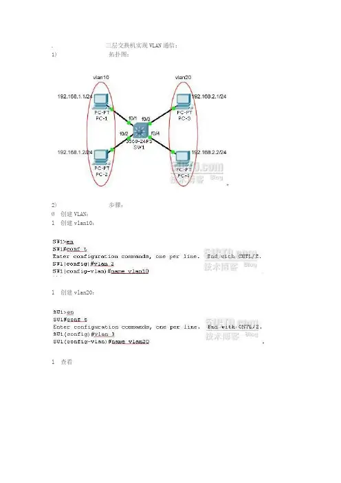
. 三层交换机实现VLAN通信:1) 拓扑图:2) 步骤:Ø创建VLAN:l 创建vlan10:l 创建vlan20:l 查看Ø把端口划分在VLAN中:l f0/1与f0/2划分在vlan10上:l f0/3与f0/4划分在vlan20上:l 查看:Ø开启路由功能:这时SW1就启用了三层功能Ø给VLAN接口配置地址:l vlan10接口配置地址:在VLAN接口上配置IP地址即可,vlan10接口上的地址就是PC-1、PC2的网关了,vlan20接口上的地址就是PC-3、PC-4的网关了。
l vlan20接口配置地址:l 查看SW1上的路由表:和路由器一样,三层交换机上也有路由表要配置三层交换机上启用路由功能,还需要启用CEF(命令为:ip cef),不过这是默认值。
和路由一样,三层交换机上同样可以运行路由协议。
Ø给PC机配置网关:分别给PC-1、PC-2、PC-3、PC-4配置IP地址和网关,PC-1、PC-2的网关指向:192.168.1.254,PC-3、PC-4的网关指向:192.168.2.254。
如果计算机有两张或两张以上的网卡,请去掉其他网卡上设置的网关。
Ø注意:也可以把f0/1、f0/2、f0/3、f0/4接口作为路由接口使用,这时他们就和路由器的以太网接口一样了,可以在接口上配置IP地址。
如果S1上的全部以太网都这样设置,S1实际上成了具有24个以太网接口的路由器了,不建议这样做,这样做太浪费接口了,配置实例:no switchport配置该接口不再是交换接口了,成为路由接口。
下面是路由器试验的单臂路由功能1) 单臂路由实现原理:VLAN间的主机通信为不同网段间的通信,需要通过三层设备对数据进行路由转发才可以实现,在路由器上对物理接口划分子接口并封装802.1q协议,使每一个子接口都充当一个VLAN 网段中主机的网关,利用路由器的三层路由功能可以实现不同VLAN间的通信。
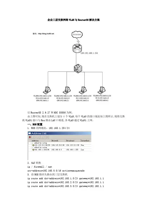
企业三层交换网络VLAN与RouterOS解决方案以RouterOS 2.9.27和H3C S5500为例。
由上图可知,现在交换机上划分4个VLAN,每个VLAN的接口地址如上图所示,现将交换机VLAN1接口与Ros路由LAN口相连,各VLAN通过VLAN1上网。
一、ROS配置1. ROS内网地址:192.168.1.254/242. NAT转换ip / firewall / natsrc-address=192.168.0.0/16 action=masquerade3. 给ROS指回头路由到三层交换机ip route add dst-address=192.168.1.0/24 gateway=192.168.1.1ip route add dst-address=192.168.2.0/24 gateway=192.168.1.1ip route add dst-address=192.168.3.0/24 gateway=192.168.1.1ip route add dst-address=192.168.4.0/24 gateway=192.168.1.1上面的这几行可以用下面这行代替ip route add dst-address=192.168.0.0/16 gateway=192.168.1.1二、H3C5500交换机配置<H3C>sysSystem View: return to User View with Ctrl+Z.[H3C]vlan 2 */依次创建vlan配置ip地址默认的vlan1和路由同网段[H3C-vlan2]port g1/0/2[H3C-vlan2]int vlan 2[H3C-Vlan-interface2]ip add 192.168.2.1 24[H3C-Vlan-interface2]vlan 3[H3C-vlan3]port g1/0/3[H3C-vlan3]int vlan 3[H3C-Vlan-interface3]ip add 192.168.3.1 24[H3C-Vlan-interface3]vlan 4[H3C-vlan4]port g1/0/4[H3C-vlan4]int vlan 4[H3C-Vlan-interface4]ip add 192.168.4.1 24[H3C]ip route 0.0.0.0 0.0.0.0 192.168.1.254 */配置缺省路由三、客户机设置客户机不能上网检查线路连接是否正确确保客户机设置的网关为其所属VLAN的IP地址,使用ping命令ping路由LAN口IP 若不通,则交换机默认路由设置错误。
如何配置三层交换机创建VLAN以下的介绍都是基于Cisco交换机的VLAN。
Cisco的VLAN实现通常是以端口为中心的。
与节点相连的端口将确定它所驻留的VLAN。
将端口分配给VLAN的方式有两种,分别是静态的和动态的。
形成静态VLAN的过程是将端口强制性地分配给VLAN的过程。
即我们先在VTP (VLAN Trunking Protocol)Server上建立VLAN,然后将每个端口分配给相应的VLAN的过程。
这是我们创建VLAN最常用的方法。
动态VLAN形成很简单,由端口决定自己属于哪个VLAN。
即我们先建立一个VMPS(VLAN Membership Policy Server)VLAN管理策略服务器,里面包含一个文本文件,文件中存有与VLAN映射的MAC地址表。
交换机根据这个映射表决定将端口分配给何种VLAN。
这种方法有很大的优势,但是创建数据库是一项非常艰苦而且非常繁琐的工作。
下面以实例说明如何在一个典型的快速以太局域网中实现VLAN。
所谓典型的局域网就是指由一台具备三层交换功能的核心交换机接几台分支交换机(不一定具备三层交换能力)。
我们假设核心交换机名称为:COM;分支交换机分别为:PAR1、PAR2、PAR3……,分别通过Port 1的光线模块与核心交换机相连;并且假设VLAN名称分别为COUNTER、MARKET、MANAGING……设置VTP DOMAINVTP DOMAIN 称为管理域。
交换VTP更新信息的所有交换机必须配置为相同的管理域。
如果所有的交换机都以中继线相连,那么只要在核心交换机上设置一个管理域,网络上所有的交换机都加入该域,这样管理域里所有的交换机就能够了解彼此的VLAN列表。
COM#vlan database 进入VLAN配置模式COM(vlan)#vtp domain COM 设置VTP管理域名称COMCOM(vlan)#vtp server 设置交换机为服务器模式PAR1#vlan database 进入VLAN配置模式PAR1(vlan)#vtp domain COM 设置VTP管理域名称COMPAR1(vlan)#vtp Client 设置交换机为客户端模式PAR2#vlan database 进入VLAN配置模式PAR2(vlan)#vtp domain COM 设置VTP管理域名称COMPAR2(vlan)#vtp Client 设置交换机为客户端模式PAR3#vlan database 进入VLAN配置模式PAR3(vlan)#vtp domain COM 设置VTP管理域名称COMPAR3(vlan)#vtp Client 设置交换机为客户端模式注意:这里设置交换机为Server模式是指允许在本交换机上创建、修改、删除VLAN及其他一些对整个VTP域的配置参数,同步本VTP域中其他交换机传递来的最新的VLAN信息;Client模式是指本交换机不能创建、删除、修改VLAN 配置,也不能在NVRAM中存储VLAN配置,但可以同步由本VTP域中其他交换机传递来的VLAN信息。
三层交换机实现三层互联的方法英文回答:To implement layer 3 connectivity using a layer 3 switch, there are several methods that can be used. One common method is to configure the switch with multiple VLANs (Virtual Local Area Networks) and then use a routing protocol to enable communication between the VLANs.Firstly, the layer 3 switch needs to be configured with the appropriate VLANs. VLANs are used to separate network traffic into different logical networks, allowing forbetter network management and security. Each VLAN will have its own subnet and IP address range.Once the VLANs are configured, the layer 3 switch needs to be configured with a routing protocol. A routing protocol is used to exchange routing information between routers and switches, allowing them to dynamically update their routing tables and determine the best path for datapackets to reach their destination.One commonly used routing protocol is OSPF (Open Shortest Path First). OSPF is a link-state routing protocol that uses the concept of areas to scale large networks. By configuring OSPF on the layer 3 switch, it can exchange routing information with other OSPF-enabled devices in the network, allowing for layer 3 connectivity between VLANs.Another method to achieve layer 3 connectivity with a layer 3 switch is to use static routes. Static routes are manually configured routes that specify the next hop for a particular destination network. By configuring static routes on the layer 3 switch, it can forward packets between VLANs based on the static route entries.In addition to VLANs and routing protocols, layer 3 switches can also support other layer 3 features such as access control lists (ACLs) and quality of service (QoS). ACLs can be used to filter traffic based on specific criteria, such as source IP address or protocol, while QoS can prioritize certain types of traffic to ensure optimalperformance.In summary, to implement layer 3 connectivity using a layer 3 switch, VLANs need to be configured to separate network traffic, and a routing protocol or static routes need to be configured to enable communication between VLANs. Other layer 3 features such as ACLs and QoS can also be utilized to enhance network security and performance.中文回答:使用三层交换机实现三层互联的方法有多种。
三层交换机进行VLAN处理过程详解1.VLAN的创建:首先,管理员需要在三层交换机上创建不同的VLAN。
每个VLAN都有一个唯一的标识符,称为VLANID。
管理员可以根据网络的需求创建不同的VLAN,并将端口分配给相应的VLAN。
2.VLAN的划分:在创建VLAN之后,管理员需要将不同的端口划分到相应的VLAN中。
这样,同一VLAN中的设备可以通过交换机进行通信,而不同VLAN中的设备之间需要经过交换机进行路由。
3.子接口的创建:为了实现不同VLAN之间的路由,管理员需要在三层交换机上创建子接口。
子接口相当于在交换机上创建了多个逻辑接口,每个子接口对应一个VLAN。
4.子接口的配置:对于每个子接口,管理员需要为其配置相应的IP地址和子网掩码。
这样,三层交换机就知道如何将数据包从一个VLAN路由到另一个VLAN。
5.交换机的路由配置:为了使三层交换机能够正确地路由数据包,管理员需要对交换机进行路由配置。
这包括设置默认网关和静态路由等。
6.VLAN间的通信:一旦上述配置完成,不同VLAN的设备就可以进行通信了。
当一个设备发送数据包到另一个VLAN时,数据包首先到达三层交换机。
交换机根据数据包的目的IP地址和子接口的配置将数据包路由到相应的VLAN。
7.VLAN的隔离:三层交换机可以通过VLAN的隔离来提高网络的安全性。
通过配置ACL(访问控制列表)和端口隔离等功能,管理员可以实现不同VLAN之间的隔离,从而防止未经授权的访问和数据泄露。
8. VLAN的互连:在一些情况下,不同楼层或不同地点的交换机之间需要进行VLAN的互连。
这可以通过将两个交换机之间的端口配置为"trunk"模式来实现。
在trunk模式下,交换机可以传输多个VLAN的数据包。
总结起来,三层交换机进行VLAN处理的过程包括VLAN的创建和划分、子接口的创建和配置、交换机的路由配置、VLAN间的通信、VLAN的隔离和VLAN的互连。
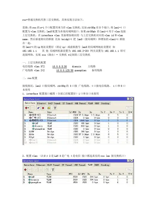
ros+普通交换机代替三层交换机,具体实现方法如下:思路:将ros的n-1个口配置用来当作vlan交换机,比如rb450g有5个端口,将lan1-4 口配置为vlan交换机,lan5配置为本地局域网接口,如果rb450gb 的lan1-4用于vlan连接上层交换机,在interface vlan 里面增加相应的与上层交换机对应的vlan id和vlan name,然后新建相应的桥接比如 bridg1-4 把 lan5(接局域网)和增加的vlan1-4 桥接在一起,将lan1-4的ip地址设置好(固定ip)或虚拟拨号 lan5的局域网地址设置好如192.168.1.1 其他局域网机器设置为 192.168.2-254 网关设置为 192.168.1.1 即可连接网络,实现 ros(路由)+ 交换机 =定制的三层交换机一、上层交换机配置电信线路 vlan 372 10.0.0.5/30 dianxin 主线路广电线路 vlan 242 10.0.0.125/30 guangdian 备用线路二、ros配置接线情况:lan2 口接局域网,rb450g的 3口接广电线路,4口接电信线路。
1口和5口未使用1、interface 配置接口截图(全部已经配置好)1口和5口未使用2、配置vlan (2\3\4 2是LAN 3是广电 4是电信接口都选真实的ros lan 接交换机口)电信vlan配置广电vlan配置类似特别强调lan还是需要vlanlan vlan 截图3、增加电信vlan(dianxin)和广电vlan(guangdian)lan口的vlan 与lan2(真实接口)的桥接,这是关键的部分,不然会只能ping通,无法打开网页、ftp连接等问题。
4、配置ip地址5、配置rip协议(你们配置自己的路由协议)5-1 配置ospf 协议(rip协议和ospf协议只能选择配置一种)三层交换机在ros里的具体做法,最好有个命令操作!我来帮他解答满意回答把所有接口放入一个桥里,然后在桥里管理接口,就可以了。


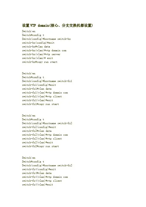
设置VTP domain(核心、分支交换机都设置)Switch>enSwitch#config tSwitch(config)#hostname switch-hxswitch-hx(config)#exitswitch-hx#vlan dataswitch-hx(vlan)#vtp domain comswitch-hx(vlan)#vtp serverswitch-hx(vlan)# exitswitch-hx#copy run startSwitch>enSwitch#config tSwitch(config)#hostname switch-fz1switch-fz1(config)#exitswitch-fz1#vlan dataswitch-fz1(vlan)#vtp domain comswitch-fz1(vlan)#vtp clientswitch-fz1(vlan)#exitswitch-fz1#copy run startSwitch>enSwitch#config tSwitch(config)#hostname switch-fz2switch-fz2(config)#exitswitch-fz2#vlan dataswitch-fz2(vlan)#vtp domain comswitch-fz2(vlan)#vtp clientswitch-fz2(vlan)#exitswitch-fz2#copy run startSwitch>enSwitch#config tSwitch(config)#hostname switch-fz2switch-fz4(config)#exitswitch-fz4#vlan dataswitch-fz4(vlan)#vtp domain comswitch-fz4(vlan)#vtp clientswitch-fz4(vlan)#exitswitch-fz4#copy run startSwitch>enSwitch#config tSwitch(config)#hostname switch-fz5Switch-fz5(config)#exitSwitch-fz5#vlan dataSwitch-fz5(vlan)#vtp domain comSwitch-fz5(vlan)#vtp clientSwitch-fz5(vlan)#exitSwitch-fz5#copy run start将端口设置为trunk端口switch-hx>enswitch-hx#config tswitch-hx(config)#int g0/1switch-hx(config-if)#switchport mode trunk switch-hx(config-if)#exitswitch-hx(config)#int g0/2switch-hx(config-if)#switchport mode trunk switch-hx(config-if)#exitswitch-hx#copy run startswitch-fz1>enswitch-fz1#config tswitch-fz1(config)#int g1/1switch-fz1(config-if)#switchport mode trunk switch-fz1(config-if)#exitswitch-fz1(config)#int f0/1switch-fz1(config-if)#switchport mode trunk switch-fz1(config-if)#exitswitch-fz1(config)#int f0/2switch-fz1(config-if)#switchport mode trunk switch-fz1(config-if)#endswitch-fz1#copy run startswitch-fz2>enswitch-fz2#config tswitch-fz2(config)#int f0/1switch-fz2(config-if)#switchport mode trunk switch-fz2(config-if)#endswitch-fz2#copy run startswitch-fz3>enswitch-fz3#config tswitch-fz3(config)#int f0/1switch-fz3(config-if)#switchport mode trunk switch-fz3(config-if)#endswitch-fz3#copy run startswitch-fz3#switch-fz4>enswitch-fz4#config tswitch-fz4(config)#int g1/1switch-fz4(config-if)#switchport mode trunk switch-fz4(config-if)#exitswitch-fz4(config)#int f0/1switch-fz4(config-if)#switch mode trunk switch-fz4(config-if)#endswitch-fz4#copy run startswitch-fz4#switch-fz5>enswitch-fz5#config tswitch-fz5(config)#int f0/1switch-fz5(config-if)#switchport mode trunk switch-fz5(config-if)#endswitch-fz5#copy run startswitch-fz5#在核心交换机上建立VLANswitch-hx(vlan)#vlan 10 name aaaVLAN 10 added:Name: aaaswitch-hx(vlan)#vlan 11 name bbbVLAN 11 added:Name: bbbswitch-hx(vlan)#将交换机端口划入VLANswitch-fz1>enswitch-fz1#config tswitch-fz1(config)#int f0/3switch-fz1(config-if)#switchport access vlan 10 switch-fz1(config-if)#exitswitch-fz1(config)#int f0/4switch-fz1(config-if)#switchport access vlan 11 switch-fz1(config-if)#endswitch-fz1#copy run startswitch-fz2>enswitch-fz2#config tswitch-fz2(config)#int f0/3switch-fz2(config-if)#switchport access vlan 10 switch-fz2(config-if)#exitswitch-fz2(config)#int f0/4switch-fz2(config-if)#switchport access vlan 11 switch-fz2(config-if)#endswitch-fz2#copy run startswitch-fz2#switch-fz3>enswitch-fz3#config tswitch-fz3(config)#int f0/3switch-fz3(config-if)#switchport access vlan 10 switch-fz3(config-if)#exitswitch-fz3(config)#int f0/4switch-fz3(config-if)#switchport access vlan 11 switch-fz3(config-if)#endswitch-fz3#copy run startswitch-fz3#switch-fz4>enswitch-fz4#config tswitch-fz4(config)#int f0/3switch-fz4(config-if)#switchport access vlan 10switch-fz4(config-if)#exitswitch-fz4(config)#int f0/4switch-fz4(config-if)#switchport access vlan 11switch-fz4(config-if)#endswitch-fz4#copy run starswitch-fz5>enswitch-fz5#config tswitch-fz5(config)#int f0/3switch-fz5(config-if)#switchport access vlan 10switch-fz5(config-if)#exitswitch-fz5(config)#int f0/4switch-fz5(config-if)#switchport access vlan 11switch-fz5(config-if)#endswitch-fz5#copy run startswitch-fz5#配置三层交换switch-hx>enswitch-hx#config tswitch-hx(config)#int vlan 10upswitch-hx(config-if)#ip add 192.168.91.254 255.255.255.0switch-hx(config-if)#exitswitch-hx(config)#int vlan 11switch-hx(config-if)#ip add 192.168.92.254 255.255.255.0switch-hx(config-if)#三层交换机默认已启动路由,ip routing命令可暂时不用,如路由被关掉,可用此命令。
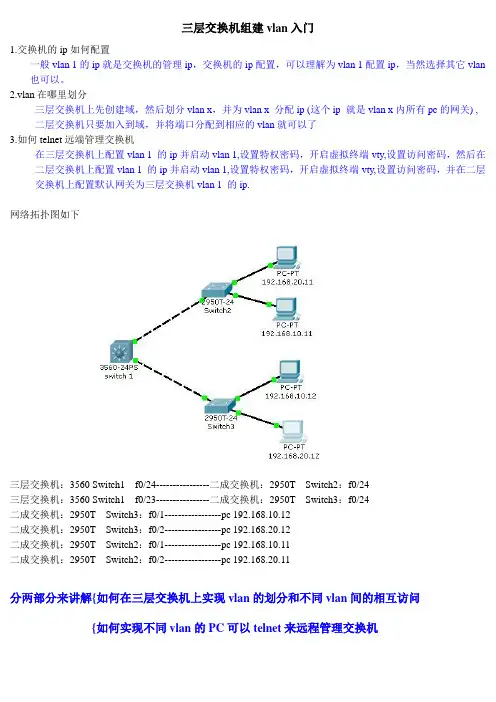
三层交换机组建vlan入门1.交换机的ip如何配置一般vlan 1的ip就是交换机的管理ip,交换机的ip配置,可以理解为vlan 1配置ip,当然选择其它vlan 也可以。
2.vlan在哪里划分三层交换机上先创建域,然后划分vlan x,并为vlan x 分配ip (这个ip 就是vlan x内所有pc的网关) ,二层交换机只要加入到域,并将端口分配到相应的vlan就可以了3.如何telnet远端管理交换机在三层交换机上配置vlan 1 的ip并启动vlan 1,设置特权密码,开启虚拟终端vty,设置访问密码,然后在二层交换机上配置vlan 1 的ip并启动vlan 1,设置特权密码,开启虚拟终端vty,设置访问密码,并在二层交换机上配置默认网关为三层交换机vlan 1 的ip.网络拓扑图如下三层交换机:3560 Switch1 f0/24----------------二成交换机:2950T Switch2:f0/24三层交换机:3560 Switch1 f0/23----------------二成交换机:2950T Switch3:f0/24二成交换机:2950T Switch3:f0/1-----------------pc 192.168.10.12二成交换机:2950T Switch3:f0/2-----------------pc 192.168.20.12二成交换机:2950T Switch2:f0/1-----------------pc 192.168.10.11二成交换机:2950T Switch2:f0/2-----------------pc 192.168.20.11分两部分来讲解{如何在三层交换机上实现vlan的划分和不同vlan间的相互访问{如何实现不同vlan的PC可以telnet来远程管理交换机如何在三层交换机上实现vlan的划分和不同vlan间的相互访问全局配置思路1.在三层交换机上配置域(server)2.在三层交换机上创建vlan3.在三层交换机上为每个vlan配置ip4.在三层交换机上配置trunk口5.在二层交换机上配置域(client)6.在二层交换机上配置trunk口7.在二层交换机上将端口分配到vlan以下为实际配置全过程,黑色部分为系统文字,蓝色部分为我输入命令或提示Switch>enable 进入特权模式Switch#config 进入全局模式Configuring from terminal, memory, or network [terminal]? Terminal 进入配置模式Enter configuration commands, one per line. End with CNTL/Z.Switch(config)#vtp domain ichia 创建域,名为ichiaChanging VTP domain name from NULL to ichiaSwitch(config)#vtp mode server 设置为域服务器Device mode already VTP SERVER.Switch(config)#exit 退出全局模式Switch#vlan database 进入vlan模式% Warning: It is recommended to configure VLAN from config mode,as VLAN database mode is being deprecated. Please consult userdocumentation for configuring VTP/VLAN in config mode.Switch(vlan)#vlan 10 创建vlan 10VLAN 10 added:Name: VLAN0010 系统默认为这个vlan分配了一个名字Switch(vlan)#vlan 20 创建vlan 20VLAN 20 added:Name: VLAN0020Switch(vlan)#exitAPPL Y completed.Exiting....Switch#config 进入全局模式Configuring from terminal, memory, or network [terminal]?Terminal 进入配置模式Enter configuration commands, one per line. End with CNTL/Z.Switch(config)#int vlan 10 进入vlan 10%LINK-5-CHANGED: Interface Vlan10, changed state to upSwitch(config-if)#ip add 192.168.10.1 255.255.255.0 为vlan 10分配ip地址,这个地址也是这个vlan的网关Switch(config-if)#exitSwitch(config)#int vlan 20%LINK-5-CHANGED: Interface Vlan20, changed state to upSwitch(config-if)#ip add 192.168.20.1 255.255.255.0Switch(config-if)#exitSwitch(config)#int f0/24 三层交换机上的24 ,23端口被用来做trunk口Switch(config-if)#switchport mode trunkCommand rejected: An interface whose trunk encapsulation is "Auto" can not be configured to "trunk" mode. 这个地方提示错误,因为需要先配置协议:dot1q 为802.1Q协议,ISL 为思科专用vlan协议Switch(config-if)#switchport trunk encapsulation dot1qSwitch(config-if)#switchport mode trunk%LINEPROTO-5-UPDOWN: Line protocol on Interface FastEthernet0/24, changed state to down%LINEPROTO-5-UPDOWN: Line protocol on Interface FastEthernet0/24, changed state to up%LINEPROTO-5-UPDOWN: Line protocol on Interface Vlan10, changed state to up%LINEPROTO-5-UPDOWN: Line protocol on Interface Vlan20, changed state to upSwitch(config-if)#exitSwitch(config)#int f0/23Switch(config-if)#switchport trunk encapsulation dot1q 设置802.1Q网络协议Switch(config-if)#switchport mode trunk 设置为trunk口%LINEPROTO-5-UPDOWN: Line protocol on Interface FastEthernet0/23, changed state to down%LINEPROTO-5-UPDOWN: Line protocol on Interface FastEthernet0/23, changed state to upSwitch(config-if)#exitSwitch(config)#exit%SYS-5-CONFIG_I: Configured from console by consoleSwitch#exitSwitch con0 is now available三层交换机部分就算设置好了下面进入到二层交换机部分Switch>enableSwitch#configConfiguring from terminal, memory, or network [terminal]?terminal Enter configuration commands, one per line. End with CNTL/Z. Switch(config)#vtp domain ichia 加入到ichia 域Domain name already set to ichia.Switch(config)#vtp mode client 在域中扮演用户端的角色Setting device to VTP CLIENT mode.Switch(config)#int f0/24 进入端口24Switch(config-if)#switchport mode trunk 设置端口为trunk口Switch(config-if)#exitSwitch(config)#int f0/1 进入端口1Switch(config-if)#switchport access vlan 10将端口分配给vlan 10 Switch(config-if)#exitSwitch(config)#int f0/2 进入端口2Switch(config-if)#switchport access vlan 20 将端口分配给vlan 20 Switch(config-if)#exitSwitch(config)#exit以上为二层交换机的配置内容交换机Switch3的配置和Switch2 基本一样配置完成后我们直接在pc上测试从图上可以看到:192.168.20.11 ping 192.168.10.11 成功192.168.20.11 ping 192.168.20.12 成功如何实现不同vlan的PC可以telnet来远程管理交换机配置思路1.三层交换机配置vlan 1 的ip,开启vlan 1,配置特权密码,开启VTY和访问密码2.二层交换机配置vlan 1 的ip,开启vlan 1 ,设置网关为三层交换机vlan 1的ip地址,配置特权密码,开启vty和访问密码。
三层交换机的配置工作原理
三层交换机是一种具有部分路由器功能的交换机,能够在OSI网络模型的第三层上进行操作。
其配置工作原理主要包括以下几个方面:
1. VLAN配置:通过创建VLAN并为其分配IP地址,可以实现不同VLAN
之间的通信。
配置步骤包括进入系统视图、创建VLAN、将端口分配给VLAN等。
2. IP地址配置:为VLAN配置IP地址,以便在三层交换机上启用路由功能。
配置步骤包括进入VLAN接口视图、配置IP地址等。
3. 路由配置:通过静态路由或动态路由协议(如OSPF、EIGRP等)配置路由信息,以实现三层交换机与其他网络设备的通信。
配置步骤包括进入系统视图、创建静态路由或配置动态路由协议等。
4. 交换机安全配置:通过配置访问控制列表(ACL)、端口安全等安全策略,可以保护三层交换机免受攻击和非法访问。
配置步骤包括进入系统视图、创建ACL或配置端口安全等。
5. 流量控制和优化:通过配置流量控制和优化策略,可以提高三层交换机的性能和可靠性。
配置步骤包括进入系统视图、配置流量控制和优化策略等。
总的来说,三层交换机的配置工作原理是通过一系列的配置步骤来实现其路由、交换和安全功能的。
这些配置步骤可以根据实际需求进行选择和调整,以满足不同的网络需求。
ROS+三层交换机vlan配置实例请看下图:环境介绍在这里我用的是ROS CCR1009 代替原先防火墙,三层交换机神州数码DCN-6804E,需要实现的是,划分多vlan,且VLAN网关设置在三层交换机上,ROS 上只做NAT转发以及回程路由,下面我们根据上图做配置,我们先在ROS上配置好外网(118.114.237.X/24)内网ETH8(10.0.0.1/24)并保证可正常上网,与三层链接的口ETH24配置为Access口,并加入VLAN100,并设置IP(10.0.0.2/24)1.ROS配置2、NAT转换/ip firewall natadd action=masquerade chain=srcnat3、路由配置/ip routeadd check-gateway=ping distance=1dst-address=192.168.10.0/24 gateway=10.0.0.2add check-gateway=ping distance=1dst-address=192.168.20.0/24 gateway=10.0.0.2add check-gateway=ping distance=1dst-address=192.168.30.0/24 gateway=10.0.0.2也可以用一条路由 192.168.0.0/16 10.0.0.2 这样也可以的。
3、DCN-6804 的配置DCRS-6804E#DCRS-6804E#sh runspanning-treespanning-tree mode rstpspanning-tree priority 4096Interface Ethernet0vlan 1;10 20 30 100firewall enableInterface Ethernet1/1switchport mode trunkInterface Ethernet1/2switchport mode trunkInterface Ethernet1/3switchport mode trunk!Interface Ethernet1/24description 接ROSLANswitchport access vlan 100Interface Ethernet1/25interface Vlan10ip address 192.168.32.1 255.255.255.0 !forward protocol udp 67(active)!ip helper-address 10.6.8.254interface Vlan20ip address 192.168.20.1 255.255.255.0 interface Vlan30ip address 192.168.30.1 255.255.255.0ip route 0.0.0.0/0 10.0.0.1 */配置缺省路由,下一跳到ros的lan口no loginendDCRS-6804E#到这里就配置完成了!。
交换机怎么设置实现三层交换功能交换机是网络中非常重要的设备,主要用于局域网中的数据交换。
传统的交换机是二层交换机,主要用于数据链路层的转发,而三层交换机则可以在网络层上实现数据的转发和路由功能。
接下来,我将详细介绍如何设置实现三层交换功能的交换机。
首先,需要说明的是,要实现三层交换功能,必须确保交换机具备三层路由功能的硬件支持。
如果交换机不支持三层功能,那么无论怎样设置都无法实现三层交换功能。
设置三层交换功能的步骤如下:第一步:连接三层交换机和路由器将三层交换机的一个接口连接到路由器的一个接口上,确保能够进行物理连通。
第二步:配置三层交换机的网络接口登录到三层交换机的管理界面,进入接口配置界面,为与路由器相连接的接口设置IP地址和子网掩码。
这些IP地址和子网掩码必须与同一个子网的其他设备相一致,以确保能够进行通信。
第三步:配置三层交换机的默认路由为了实现三层交换机的通信功能,需要设置默认路由。
在三层交换机的管理界面中,找到路由表配置界面,添加一条默认路由项,将下一跳设置为与交换机相连接的路由器的IP地址。
第四步:配置交换机的VLANVLAN是虚拟局域网,可以将不同的接口分为不同的VLAN,实现不同VLAN之间的隔离。
在三层交换机的管理界面中,进入VLAN配置界面,创建所需的VLAN,并将相应的接口加入到对应的VLAN中。
第五步:配置三层交换机的子接口子接口允许三层交换机同时连接到多个不同的子网,实现不同子网之间的转发。
在三层交换机的管理界面中,进入子接口配置界面,为每个需要连接的子网创建一个子接口,并在子接口上配置对应的IP地址和子网掩码。
第六步:配置三层交换机的路由协议路由协议是用于交换和更新路由表的机制。
根据实际情况选择适合的路由协议,如OSPF、RIPv2等,并在三层交换机上进行相应的配置。
第七步:配置三层交换机的ACL和QoS访问控制列表(ACL)用于过滤和限制网络中的数据流,提高网络的安全性。
三层交换VLAN路由配置技巧详解三层交换VLAN路由配置技巧详解在华为三层交换机上创建VLAN,端口划分,三层VLAN接口地址配置,静态路由或是RIP协议配置。
跟店铺来学习一下配置过程。
静态路由配置过程:PCA:ip address:10.1.1.2/24 gw:10.1.1.1/24(VLAN2路由接口IP 地址)PCB:ip address:10.1.2.2/24 gw:10.1.2.1/24(VLAN3路由接口IP 地址)PCC:ip address:10.1.3.2/24 gw:10.1.3.1/24(VLAN2路由接口IP 地址)S3526A和S352B之间的`互联网段为10.1.4.0、24分配S3526A VLAN4路由接口IP地址为10.1.4.1/24,S3526B VLAN4路由接口IP地址为10.1.4.2/24三层交换机配置创建VLAN,把PC划到特定VLAN中://创建VLAN[S3526A]vlan 2//把端口划到VLAN中[S3526A-VLAN 2]port ethernet0/9 to ethernet0/12[S3526A-VLAN 2]vlan 3[S3526A-VLAN 2]port ethernet0/13 to ethernet0/16[S3526A-VLAN 2]vlan 4//交换机B的配置:[S3526B]vlan 2[S3526B-VLAN 2]port ethernet0/9 to ethernet0/12[S3526B-VLAN 2]vlan 4配置各台PC的网关地址和交换机之间的网段地址://进入VLAN接口配置模式:[S3526A]interface Vlan-interface 2//配置三层VLAN路由接口地址[S3526A-Vlan-interface2]ip address 10.1.1.1 255.255.255.0 [S3526A-Vlan-interface2] interface Vlan-interface 3[S3526A-Vlan-interface3]ip address 10.1.2.1 255.255.255.0 [S3526A-Vlan-interface3] interface Vlan-interface 4[S3526A-Vlan-interface4]ip address 10.1.4.1 255.255.255.0 [S3526B]interface Vlan-interface 2[S3526B-Vlan-interface2]ip address 10.1.3.1 255.255.255.0 [S3526B-Vlan-interface2] interface Vlan-interface 4[S3526B-Vlan-interface4]ip address 10.1.4.2 255.255.255.0 在二台三层交换机上配置非直连网段静态路由:[S3526A]ip route-static 10.1.3.0 255.255.255.0 10.1.4.2 [S3526B]ip route-static 10.1.1.0 255.255.255.0 10.1.4.1 [S3526B]ip route-static 10.1.2.0 255.255.255.0 10.1.4.1查看路由表,查看网络互通情况:[S3526B]display ip routing-tableRouting Table: public netDestination/Mask Proto Pre Cost Nexthop Interface10.1.1.0/24 STATIC 60 0 10.1.4.1 Vlan-interface410.1.2.0/24 STATIC 60 0 10.1.4.1 Vlan-interface410.1.3.0/24 DIRECT 0 0 10.1.3.1 Vlan-interface210.1.3.1/32 DIREC T 0 0 127.0.0.1 InLoopBack010.1.4.0/24 DIRECT 0 0 10.1.4.2 Vlan-interface40.1.4.2/32 DIRECT 0 0 127.0.0.1 InLoopBack0127.0.0.0/8 DIRECT 0 0 127.0.0.1 InLoopBack0127.0.0.1/32 DIRECT 0 0 127.0.0.1 InLoopBack0RlP协议在三层交换机上的配置1.继续上面的,删除前面配置的静态路由。
ROS配合L3交换机设置VLAN在写这篇文章之前,首先鸣谢:中国石化中原石油化工有限责任公司信息科,任哥、苌哥,感谢他们能给我提供一个学习技术的良好平台,以及对我生活上无私的帮助。
还有濮阳市新锐科电子有限公司王哥给我提供技术支持!下面进入正题:试验要求:1.设置路由器W AN口IP为10.97.36.92.设置路由器LAN口IP为192.168.100.13.设置两个网段:192.168.101.X 192.168.102.X,两个网段能相互访问4.A机IP192.168.101.11 B机:192.168.102.22先介绍下我这的设备:1.ROS2.9.272.H3C S3600 交换机一台。
首先给大家拓扑图:首先配置交换机:[H3C]vlan 2 #创建VLAN 2[H3C]interface vlan 2[H3C-Vlan-interface2]ip add 192.168.100.2 255.255.255.0 #设置VLAN 2 的IP(VLAN 2是和ROS的内网连接的)[H3C-Vlan-interface2]qui[H3C]vlan 2[H3C-vlan2]por[H3C-vlan2]port e1/0/2 #划分交换机的2号端口到VLAN 2[H3C-vlan2]%Apr 1 23:57:19:969 2000 H3C L2INF/5/VLANIF LINK STATUS CHANGE:- 1 - Vlan-interface2: is UP%Apr 1 23:57:20:082 2000 H3C IFNET/5/UPDOWN:- 1 -Line protocol on the interface Vlan-interface2 is UP[H3C-vlan2]vlan 3 #创建VLAN 3[H3C-vlan3]por[H3C-vlan3]port e1/0/4 #划分交换机的4号端口到VLAN 3[H3C-vlan3]qui[H3C]int vlan 3[H3C-Vlan-interface3]%Apr 1 23:57:56:363 2000 H3C L2INF/5/VLANIF LINK STATUS CHANGE:- 1 - Vlan-interface3: is UP[H3C-Vlan-interface3]ip add 192.168.101.1 255.255.255.0 #设置VLAN 3 的IP[H3C-Vlan-interface3]%Apr 1 23:58:08:455 2000 H3C IFNET/5/UPDOWN:- 1 -Line protocol on the interface Vlan-interface3 is UP[H3C-Vlan-interface3]vlan 4 #创建VLAN 4[H3C-vlan4]por[H3C-vlan4]port e1/0/6 #划分交换机的6号端口到VLAN 4[H3C-vlan4]qui[H3C]int vlan 4[H3C-Vlan-interface4]%Apr 1 23:58:39:721 2000 H3C L2INF/5/VLANIF LINK STATUS CHANGE:- 1 - Vlan-interface4: is UP[H3C-Vlan-interface4]ip add 192.168.102.1 255.255.255.0 #设置VLAN 4 的IP[H3C-Vlan-interface4]%Apr 1 23:58:50:069 2000 H3C IFNET/5/UPDOWN:- 1 -Line protocol on the interfaceVlan-interface4 is UP[H3C-Vlan-interface4]qui[H3C]ip co[H3C]ip ro[H3C]ip route-static 0.0.0.0 0.0.0.0 192.168.100.1 #添加路由,192.168.100.1是目的地址,在这里也就是ROS内网的IP交换机到这里设置完成!现在两机之间可以正常访问,但是无法上外网!如图所示:(PC A)(PC B)下面设置ROS:ROS的安装在这里不在赘述。
ROS+三层交换机vlan配置实例
请看下图:
环境介绍
在这里我用的是ROS CCR1009 代替原先防火墙,三层交换机神州数码DCN-6804E,需要实现的是,划分多vlan,且VLAN网关设置在三层交换机上,ROS 上只做NAT转发以及回程路由,下面我们根据上图做配置,我们先在ROS上配置好外网(118.114.237.X/24)内网ETH8(10.0.0.1/24)并保证可正常上网,与三层链接的口ETH24配置为Access口,并加入VLAN100,并设置IP(10.0.0.2/24)
1.ROS配置
2、NAT转换
/ip firewall nat
add action=masquerade chain=srcnat
3、路由配置
/ip route
add check-gateway=ping distance=1 dst-
address=192.168.10.0/24 gateway=10.0.0.2
add check-gateway=ping distance=1 dst-
address=192.168.20.0/24 gateway=10.0.0.2
add check-gateway=ping distance=1 dst-
address=192.168.30.0/24 gateway=10.0.0.2
也可以用一条路由 192.168.0.0/16 10.0.0.2 这样也可以的。
3、DCN-6804 的配置
DCRS-6804E#
DCRS-6804E#sh run
spanning-tree
spanning-tree mode rstp
spanning-tree priority 4096
Interface Ethernet0
vlan 1;10 20 30 100
firewall enable
Interface Ethernet1/1
switchport mode trunk
Interface Ethernet1/2
switchport mode trunk
Interface Ethernet1/3
switchport mode trunk
!
Interface Ethernet1/24
description 接ROSLAN
switchport access vlan 100
Interface Ethernet1/25
interface Vlan10
ip address 192.168.32.1 255.255.255.0 !forward protocol udp 67(active)!
ip helper-address 10.6.8.254
interface Vlan20
ip address 192.168.20.1 255.255.255.0 interface Vlan30
ip address 192.168.30.1 255.255.255.0
ip route 0.0.0.0/0 10.0.0.1 */配置缺省路由,下一跳到ros 的lan口
no login
end
DCRS-6804E#
到这里就配置完成了!。