电气专业毕业设计外文翻译2--变压器
- 格式:docx
- 大小:72.29 KB
- 文档页数:6

变压器常用术语TECHNICAL TERMS COMMONLY USED FOR TRANSFORMERPART 1产品名称及类型1.1电力变压器Power transformer1.2芯式变压器core type transformer内铁式变压器core-form transformer 1.3壳式变压器shell-form transformer外铁式变压器shell-form transformer 1.4 密封式变压器sealed transformer1.5 有载调压电力变压器power transformer with OLTC1.6 无载调压电力变压器power transformer with off-circuit tap-changer1.7 配电变压器distribution transformer1.8 自耦变压器auto-transformer1.9 联络变压器interconnecting transformer 1.10升压变压器step-up transformer1.11降压变压器step-down transformer1.12 增压变压器booster transformer串联变压器1.13 发电机变压器generator transformer 1.14 电站用变压器substation transformer 1.15 交流变压器converter transformer 1.16 分裂变压器split-winding type transformer1.17 厂用变压器power plant transformer 1.18 所用变压器electric substation transformer1.19 单相变压器single-phase transformer 1.20 三相变压器three-phase transformer 1.21 多相变压器polyphase transformer 1.22 单相变压器组成的三相组three-phase banks with separate single-phase transformer 1.23 三相接地变压器three-phase earthing transformer1.24 三线圈变压器three-winding transformer1.25 两线圈变压器two-winding transformer1.26 双线圈变压器double-winding transformer1.27 多线圈变压器multi-winding transformer 1.28 油浸式变压器oil-immersed type transformer1.29 浸难燃油变压器noninflammable medium impregnated transformer1.30 干式变压器dry type transformer1.31 树脂浇注式变压器resin-casting type transformer1.32 H级绝缘变压器transformer with H class insulation1.33 气体绝缘变压器gas insulated transformer1.34 电炉变压器furnace transformer1.35 整流变压器rectifier transformer1.36 列车牵引变压器traction transformer, locomotive transformer1.37 矿用变压器mining transformer1.38 防爆变压器explosion-proof transformer flame-proof transformer1.39 隔离变压器isolation transformer1.40 试验变压器testing transformer1.41 串级式试验变压器cascade testing transformer1.42 串联变压器series transformer1.43 增压变压器booster transformer1.44 灯丝变压器filament transformer1.45 电焊变压器welding transformer1.46 钎焊变压器brazing transformer1.47 船用变压器marine transformer1.48 起动自耦变压器starting autotransformer1.49 起动变压器starting transformer1.50 移动变压器movable substation1.51 移动式movable type1.52 成套变电站complete substation1.53 全自动保护单相变压器complete self-protected single-phase transformer(CSP) 1.54 互感器instrument transformer1.55 测量用互感器measurement current/voltage TR1.56 保护用互感器protective current/voltage transformer1.57 电流互感器current transformer(CT)1.58 电压互感器voltage transformer potential transformer(PT)1.59 全绝缘电流互感器fully insulatedcurrent transformer1.60 母线式电流互感器bus-type current transformer1.61 绕线式电流互感器wound primary type current transformer1.62 瓷箱式电流互感器porcelain type current transformer1.63 套管用电流互感器bushing-type current transformer1.64 电容式电流互感器capacitor type current transformer1.65 支持式电流互感器support-type current transformer1.66 倒立式电流互感器reverse type current transformer1.67 塑料浇注式电流互感器cast resin current transformer1.68 钳式电流互感器split-core type current transformer1.69 速饱和电流互感器rapid-saturable current transformer1.70 串级式电流互感器cascade-type current transformer1.71 剩余电流互感器residual current transformer1.72 电容式电压互感器capacitor type voltage transformer1.73 接地电压互感器earthed voltage transformer1.74 不接地电压互感器unearthed voltage transformer1.75 组合式互感器combined instrument transformer1.76 剩余电压互感器residual voltage transformer1.77 移圈调压器moving-coil voltage transformer1.78 动线圈moving winding1.79 自耦调压器autoformer regulator1.80 接触调压器variac1.81 感应调压器induction voltage regulator 1.82 磁饱和调压器magnetic saturation voltage regulator1.83 电抗器reactor1.84 并联电抗器shunt reactor 1.85 串联电抗器series reactor1.86 饱和电抗器saturable reactor1.87 铁心电抗器iron core reactor1.88 空心电抗器air core reactor1.89 水泥电抗器concrete(cement) reactor 1.90 三相中性点接地电抗器three-phase neutral reactor1.92 单相中性点接地电抗器single-phase neutral earthing reactor1.93 起动电抗器starting reactor1.94 平衡电抗器smoothing /interphase reactor1.95 调幅电抗器modulation reactor1.96 消弧电抗器arc-suppression reactor 1.97 消弧线圈arc-suppression coil1.98 阻波器,阻波线圈wave trap coil1.99 镇流器ballast1.100 密闭式sealed type1.101 包封式enclosed type1.102 户外式outdoor type1.103 户内式indoor type1.104 柱上式pole mounting type1.105 移动式movable type1.106 列车式trailer mounted type1.107 自冷natural cooling (ONAN)1.108 风冷forced-air cooling (ONAF)1.109 强油风冷forced-oil forced-air cooling(ONAF)1.110 强油水冷forced-oil forced-water cooling (ONWF)1.111 强油导向冷却forced-directed oil cooling (OFAN)1.112 强油导向风冷却forced-directed forced-air oil cooling(ODAF)1.113 恒磁通调压constant flux voltage variation(CFVV)1.114 变磁通调压variable flux voltage variation(VFVV)1.115 混合调压combined voltage variation(CbVV)PART2 基础词汇2.1 千瓦kilowatt(kw)2.2 兆瓦megawatt(MW)2.3 京瓦gigawatt(GW)2.4 千伏kilovolt(kV)2.5 兆伏megavolt(MV)2.6 京电子伏giga-electron-volt(GEV)2.7 千伏安KVA2.8 兆伏安MV A2.9 京伏安GV A2.10 千乏kilovar(kV Ar)2.11 兆乏megavar(MV Ar)2.12 京乏gigavar(GV Ar)2.13 产品代号symbol of product2.14 产品型号type of product2.15 额定电压rated voltage2.16 额定容量rated power2.17 额定电流rated current2.18 连接组标号connection symbol, symbol of connection2.19 阻抗电压impedance voltage2.20 额定频率rated frequency2.21 空载损耗no-load loss2.22 涡流损耗eddy-current loss2.23 磁滞损耗hysteresis loss2.24 空载电流no-load current2.25 激磁电流exciting current2.26 负载损耗load loss2.27 附加损耗additional losses, supplementary load loss2.28 杂散损耗stray losses2.29 总损耗total losses2.30 损耗比loss ratio2.31 冷却方式type of cooling2.32 介质损耗dielectric loss2.33 介损角正切值loss tangent2.34 电压组合voltage combination2.35 电抗电压reactance voltage2.36 额定电压比rated voltage ratio2.37 电阻电压resistance voltage2.38 电压调整率voltage regulation2.39 相位差phase displacement2.40 相位差校验phase displacement verification2.41 零序阻抗zero-sequence impedance 2.42 短路阻抗short-circuit impedance2.43 磁通密度flux density2.44 电流密度current density2.45 安匝数number of ampere-turns2.46 轴向漏磁通axial leakage flux 2.47 径向漏磁通radial leakage flux2.48 循环电流circulating current2.49 热点hot spot2.50 最热点hottest spot2.51 局部过热local overheat2.52 有功输出active output2.53 满容量分接fully-power tapping2.54 额定级电压rated step voltage2.55 最大额定电压maximum rated voltage 2.56 最大额定电流maximum rated through-current2.57 绕组额定电压rated voltage of a winding2.58 额定短时电流rated short time current 2.59 额定短时热电流rated short thermal current2.60 额定连续热电流rated continuous current2.61 额定动稳定电流rated dynamic current 2.62 一次电流/电压primary current/voltage 2.63 二次电流/电压secondary current/voltage2.64 实际电流比actual transformation ratio of a current transformer2.65 实际电压比actual transformation ratio of a voltage transformer2.66 二次极限感应电动势secondary limiting e.m.f.2.67 互感器的二次回顾路secondary circuit of CT and PT2.68 定额rating2.69 铁心噪声noise of core2.70 背境噪声background noise2.71 噪声水平noise level2.72 声级sound level2.73 声功率级sound power level2.74 声级试验sound level test2.75 声级测量sound level measurement 2.76水平加速度horizontal acceleration2.77 垂直加速度vertical acceleration2.78 地震seism, earthquake2.79 地震烈度earthquake intensity2.80 工频power-frequency2.81 中频medium frequency2.82 高频high frequency2.83 振荡频率oscillating frequency2.84 谐振频率resonance frequency2.85 自振频率natural frequency of vibration 2.86 频率响应frequency response2.87 谐波测量harmonics measurement2.88 绝缘水平insulation level2.89 绝缘强度insulation strength, dielectric strength2.90 主绝缘main insulation2.91 纵绝缘longitudinal insulation2.92 内绝缘internal insulation2.93 外绝缘external insulation2.94 绝缘配合insulation co-ordination2.95 全绝缘uniform insulation2.96 半绝缘non-uniform insulation2.97 降纸绝缘reduced insulation2.98 中心点neutral point2.99 中心点端子neutral terminal2.100 正常绝缘normal insulation2.101 介电常数dielectric constant2.102 油纸绝缘系统oil-paper insulation system2.103 绝缘电阻insulation resistance2.104 绝缘电阻吸收比absorption ratio of insulation resistance2.105 绝缘击穿insulation breakdown2.106 碳化carbonization2.107 爬电距离creepage distance2.108 沿面放电creeping discharge2.109 放电discharge2.110 局部放电partial discharge2.111 局部放电测量measurement of partial discharge2.112 超声定位ultrasonic location, ultrasonic orientation2.113 破坏性放电disruptive discharge2.114 局部放电起始电压partial discharge inception voltage2.115 局部放电终止电压partial discharge extinction voltage2.116 过电压overvoltage2.117 短时过电压short time overvoltage 2.118 瞬时过电压transient overvoltage2.119 操作过电压switching overvoltage 2.120 大气过电压atmospheric overvoltage 2.121 额定耐受电压rated withstand voltage 2.122 工频耐受电压power-frequency withstand voltage2.123 感应耐压试验induced overvoltage withstand test2.124 温升试验temperature-rise test2.125 温升temperature rise2.126 突发短路试验short-circuit test2.127 动热稳定thermo-dynamic stability 2.128 冲击耐压试验impulse voltage withstand test2.129 雷电冲击耐受电压lightning impulse withstand voltage2.130 操作冲击耐受电压switching impulse withstand voltage2.131 雷电冲击lightning impulse2.132 全波雷电冲击full wave lightning impulse2.133 截波雷电冲击chopped wave lightning impulse2.134 操作冲击switching impulse2.135 操作冲击波switch surge, switch impulse2.136 伏秒特性voltage-time characteristics 2.137 截断时间time to chopping2.138 波前时间time to crest2.139 视在波前时间virtual front time2.140 半峰值时间time to half value crest 2.141 峰值peak value, crest value2.142 有效值root-mean-square value2.143 标么值per unit value2.144 标称值nominal value2.145 电级electrode2.146 电位梯度potential gradient2.147 等电位,等位equipotential2.148 屏蔽shielding2.149 静电屏蔽electrostatic shielding2.150 磁屏蔽magnetic shielding2.151 静电屏electrostatic screen2.152 静电板electrostatic plate2.153 静电环electrostatic ring2.154 电磁感应electro-magnetic induction 2.155 电磁单元electro-magnetic unit2.156 有效面effective surface2.157 标准大气条件standard atmosphericcondition2.158 视在电荷apparent charge2.159 体积电阻volume resistance2.160 导电率admittance2.161 电导conductance, conductivity2.162 电晕放电corona discharge2.163 闪络flashover2.164 避雷器surge arrestor2.165 避雷器的残压residual voltage of an arrestor2.166 绝缘材料耐温等级temperature class of insulation2.167 互感器额定负荷rated burden of an instrument transformer2.168 准确级次accuracy class2.169 真值true value2.170 允差tolerance2.171 比值误差校验ratio error verification 2.172 电流误差current error2.173 电压误差voltage error2.174 互感器相角差phase displacement of instrument transformer2.175 复合误差composite error2.176 瞬时特性transient characteristic2.177 瞬时误差transient error2.178 额定仪表保安电流rated instrument security current2.179 二次极限感应电势secondary limitinge.m.f2.180 保安因子security factor2.181 额定准确限值的一次电流rated accuracy limit primary current2.182 误差补偿error compensation2.183 额定电压因子rated voltage factor 2.184 准确限值因子accuracy limit factor 2.185 开断电流switched current2.186 笛卡尔坐标,直角坐标Cartesian coordinate2.187 极坐标polar coordinate2.188 横坐标abscissa2.189 纵坐标ordinate2.190 X-轴X-axis2.191 复数complex number2.192 实数部分real component2.193 虚数部分imaginary component 2.194 正数positive number2.195 负数negative number2.196 小数decimal2.197 四舍五入round off2.198 分数fraction2.199 分子numerator2.200 分母denominator2.201 假分数improper fraction2.202 钝角obtuse angle2.203 锐角acute angle2.204 补角supplementary angle2.205 余角complement angle2.206 平行parallel2.207 垂直perpendicular2.208 乘方involution2.209 开方evolution, extraction of root2.210 n的5次方5th power of n2.211 幂exponent, exponential2.212 微分,差动differential, differentiate 2.213 积分,集成integral, integrate2.214 成正比proportional to….2.215 成反比inversely proportional to…2.216 概率probability2.217 归纳法inductive method2.218 外推法extrapolation method2.219 插入法interpolation method2.220 最大似然法maximum likelihood method2.221 图解法graphic method2.222 有限元法finite element method2.223 模拟法simulation method2.224 方波回应step response2.225 迭加电荷superimposed charge2.226 杂散电容stray capacitance2.227 无损探伤non-distractive flaw detection2.228 红外线扫描infrared scanning2.229 计算机辅助设计computer aided design(CAD)2.230 计算机辅助制造computer aided manufacturing(CAM)2.231 计算机辅助试验computer aided test(CAT)2.233 近似于approximate(approx)2.234 每分钟转数revolution perminute(rpm)2.235 速度velocity2.236 加速度acceleration2.237 重力加速度gravitational acceleration 2.238 引力traction2.240 件数pieces2.242 缩写abbreviation2.243 以下简称为hereinafter referred as xxx2.244 常用单位units commonly used2.245 包括缩写including abbreviations2.246 分米decimeter 厘米centimeter2.247 海里knot2.248 码yard2.249 磅pound(1b) 磅/平方英寸pound per square inch(ppsi)2.251 英制热量单位British thermal unit (BTU)2.252 马力horsepower2.253 压强intensity of pressure2.254 帕斯卡Pascal(Pa)2.255 千帕kpa 兆帕Mpa2.256 粘度viscosity2.257 帕斯卡秒pascal.second2.258 泊poise 厘泊centipoises2.259 焦耳joule(J) 千瓦时kilowatt-hour(kwh)2.260 特斯拉tesla(T) 高斯gaue(Gs)2.261 奥斯特oersted(0e) 库仑coulomb(C) 2.262 微微库Pico-coulomb(PC)2.263 达因dyne2.264 摄氏度Celsius, centigrade(℃)2.265 开尔文Kelvin 法拉farad(F)2.266 皮可法拉pico-farad(pF)2.268 立方分米cubic decimeter立方厘米cubic centimeter2.269 桶barrel 石油petroleum2.270 标准国际单位制standard international unit2.271 厘米-克秒单位制CGS unit2.272 环境设备ambience apparatus2.273 校验calibration2.274 兼容性compatibility2.275 扩散系数diffusion coefficient2.276 故障fault 2.277 公顷hectarePART3 典型产品结构3.1 芯式,内铁式core type3.2 壳式,外铁式shell type3.3 铁心core3.4 磁路magnetic circuit3.5 线圈winding, coil3.6 高压线圈HV winding3.7 中压线圈MV winding3.8 低压线圈LV winding3.9 调压线圈tapped winding, regulating winding3.10 高压引线high-voltage leads3.11 中压引线mid-voltage leads3.12 低压引线low-voltage leads3.13 夹件clamping frame3.14 上部夹件upper clamping3.15 下部夹件lower clamping3.16线圈压紧螺栓winding compressing bolt 3.17线圈压紧装置winding compressing device3.18 线圈端部绝缘end insulation of winding3.19 器身定位装置positioning device for active-part3.20 定位装置fixing device3.21 铁心垫脚foot-plate of core3.22 垫脚foot-pad3.23 分接引线tapping leads, tap leads3.24 引线支架supporting frame for leads 3.25 无励磁分接开关non-excitation tap-changer3.26 无载分接开关off-circuit tap-changer 3.27 分接选择器tap selector3.28 有载分接开关on-load tap-changer(OLTC) on-circuit tap-changer 3.29 切换开关diverter switch3.30 选择开关selector switch3.31 转换选择器change-over selector3.32 粗选择器coarse tap selector3.33 触头组set of contacts3.34 过度触头transition contacts3.35 过度阻抗transition impedance3.36 有载开关操纵机构operating mechanism of OLTC3.37 驱动机构driving mechanism3.38 电动机构motor drive3.39 垂直转动轴vertical driving shaft水平转动轴horizontal driving shaft 3.40 伞尺轮盒bevel gear box3.41 防雨罩drip-proof cap3.42 联轴节coupling3.43 最大分接maximum tapping最小分接minimum tapping3.44 额定分接rated tapping, principal tapping3.45 固定分接位置数number of inherent tapping positions工作分接位置数number of service tapping positions3.46 主分接principal tap, main tap正分接plus tapping负分接minus tapping3.47 分接变换操作tap-changer operation 3.48 分接位置指示器tap position indicator 3.49 线圈分接电压tapping voltage of a winding3.50 线圈分接电流tapping current of a winding3.51 线圈分接容量tapping power of a winding3.52 分接范围tapping range3.53 分接量tapping quantities3.54 分接因子tapping factor3.55 分接工作能力tapping duty3.56 分接线tapping step3.57 分接线tapping connection3.58 分接引线tapping lead3.59 小车支架及滚轮bogie frame and wheel3.61 箱底tank bottom3.62 箱盖tank cover3.63 箱沿tank rim3.64 垫脚垫块supporting block for foot-pad 3.65 联管接头tube connector3.66 联接法兰connecting flange3.67 加强筋,加强板stiffener3.68 油箱垂直加强铁vertical stiffening channel of tank wall3.69 油箱活门oil sampling valve3.70 放油活门oil drainningvalve 3.71 冷却器cooler3.72 集中安装concentrated installation3.73 集中安装强油循环风冷器concentrated installation of forced-oil circulating air cooler3.74 冷却器进口inlet of cooler冷却器出口outlet of cooler3.75 潜油泵oil-submerged pump3.76 油流继电器oil flow relay3.77 净油器oil filter3.78 虹吸净油器oil siphon filter3.79 散热器radiator3.80 片式散热器panel type radiator3.81 管式散热器tubular radiator3.82 放油塞oil draining plug3.83 放气塞air exhausting plug3.84 蝶阀radiator valve butterfly valve 3.85 风扇支架supporting frame for fan motors3.86 风扇及电机fan and motor3.87 风扇接线盒connecting box for fan motors3.88 储油柜conservator3.89 油位计oil-level indicator3.90 气体继电器gas relay, buchholz realy 3.91 皮托继电器pitot relay3.92 储油柜联管elbow joint for conservator 3.93 有载开关用储油柜conservator for OLTC3.94 有载开关用气体继电器gas relay for OLTC3.95 联管tube connector3.96 吸湿器dehydrating breather3.97 铭牌rating plate3.98 温度计thermometer3.98 指示仪表柜cabinet panel for indicating instruments3.99 风扇控制柜cabinet panel for fan motor control3.100 压力释放阀pressure-relief valve3.101 安全气道explosion-proof pope3.102 膨胀器expander3.103 主排气导管main gas-conduit3.104 分支导气管branching gas-conduit 3.105 滤油界面tube connector for oil-filter3.106 温度计座thermometer socket3.107 储油柜支架supporting frame for conservator3.108 高压套管HV bushing3.109 高压套管均压球equipotential shielding for HV bushing3.110 高压零相套管HV neutral bushing, HV bushing phase03.111 中压套管MV bushing3.112 中压零相套管MV neutral bushing, MV bushing phase03.113 低压套管LV bushing3.114 接地套管earthing bushing3.115 极性polarity3.116 极化polarization3.117 高压套管储油柜conservator for HV bushing3.118 相间隔板interphase insulating barrier 3.119 吊攀lifting lug3.120 安装轨道installation rail3.121 相序标志牌designation mark of phase sequence3.122 接地螺栓earthing bolt3.123 视察窗inspection hole3.124 手孔handhole3.125 人孔manhole3.126 MR有载开关MR OLTC3.127 ABB 有载开关ABB OLTC3.128 伊林有载开关ELIN OLTC3.129 F&套管F&G bushingPART4 铁心结构4.1 多框式铁心multi-frame type core4.2 三相三柱铁心three-phase three-limb core4.3 三相五柱铁心three-phase five-limb core4.4 卷铁心wound core4.5 冷轧晶粒取向硅钢片cold-rolled grain-oriented silicon sheet steel4.6 晶粒crystalline grain4.7 高导磁硅钢片HI-B silicon sheet steel 4.8 铁心片core lamination4.9 一迭铁心a lamination stock4.10 铁心迭积图lamination drawing, lamination diagram 4.11 迭片lamination4.12 迭片系数lamination factor4.13 空间利用系数space factor4.14 层间绝缘layer insulation4.15 斜接缝mitring4.16 45°斜接缝45°mitred joint4.17 斜接缝的交错排列方式over-lay arrangement for mitred joints of lamination 4.18 重迭overlap4.19 铁心油通oil-duct of core4.20 铁心气道air ventilating duct of core 4.21 阶梯接缝stepped lay joint4.22 对接铁心butt jointed core4.23 渐开线铁心evolute core, involute core 4.24 空气隙air gap4.25 铁心拉板tensile plate of core limb, core drawplate4.26 铁心柱core limb, core lge4.27 轭,铁轭yoke4.28 上轭upper yoke下轭lower yoke旁轭side yoke, return yoke4.29 环氧绑扎带epoxy-bonded bandage 4.30 轭拉带yoke tensile belt4.31 铁轭拉带banded band of core yoke 4.32 上轭顶梁top jointing beam of upper yoke4.33 侧梁side beam4.34 夹件clamping frame4.35 铁心夹件core clamps, coreframe4.36 铁轭夹件yoke clamping, yoke clamps 4.37 上夹件upper yoke clamping, upper yoke clamps4.38 下夹件lower yoke clampings, lower yoke clamps4.39 夹件腹板web of yoke clamping4.40 夹件肢板limb of yoke clamping4.41 夹件加强stiffening plate of clamping 4.42 压线圈的压钉winding compressing bolt4.43 压钉螺母nut for compressing bolt4.44 弹簧压钉compressing bolt with spring 4.45 油缸压钉compressing bolt with hydraulic damper4.46 线圈支撑架winding supporter4.47 线圈支撑架winding supporting plate 4.48 垫脚foot pad4.49 定位孔positioning hole4.50 带螺母的定位柱positioning stud4.51 拉螺杆tensile rod4.52 夹件夹紧螺杆yoke clamping bolt4.53 铁心接地片core earthing strip4.54 铁心地屏earthing screen of code4.55 旁轭地屏earthing screen of side yoke 4.56 接地屏蔽earthing shield4.57 铁心窗高core window height4.58 中心距M center line distance M4.59 铁心中间距center distance between lombs4.60 木垫块wood padding block4.61 迭片系数lamination factor4.62 铁心的级stage of lamination stacks 4.63 心柱外接圆circumscribed circle of core leg4.64 铁心端面core surface perpendicular to lamination4.65 木棒wood bar, wood rod4.66 定位板positioning platePART5 线圈结构5.1 圆筒式线圈cylindrical winding5.2 层式线圈layer winding5.3 饼式线圈disk winding5.4 单层圆筒式线圈single layer cylindrical winding5.5 双层圆筒式线圈double layer cylindrical winding5.6 多层圆筒式线圈multi-layer cylindrical winding5.7 大型层式线圈large size long layer winding5.8 分段圆筒式线圈sectional layer winding 5.9 分段多层圆筒线圈sectional multi-layer winding5.10 连续式线圈continuous winding5.11 半连续式线圈semi-continuous winding5.12 纠结式线圈interleaved winding5.13 纠结饼式线圈interleaved disc winding 5.14 纠结—连续式线圈interleaved-continuous winding 5.15 部分纠结式线圈partial-interleaved winding5.16 插花纠结式线圈sandwich-interleaved winding5.17 内屏连续式线圈innershield-continuous winding5.18 插入电容式线圈capacitor shield winding5.19 高串联电容线圈high series capacitance winding5.20 双饼式线圈twin-disk winding5.21 交错式线圈sandwich winding, staggered winding5.22 螺旋式线圈helical winding, helix winding5.23 半螺旋式线圈semi-helical winding 5.24 单列螺旋式线圈single-row helical winding5.25 双列螺旋式线圈double-row helical winding5.26 三列螺旋式线圈three-row helical winding5.27 短螺旋式线圈short helical winding 5.28 螺旋式线圈引出端的固定terminal fixing for helical winding5.29 分裂式线圈split winding5.30 分段式线圈sectional winding5.31 箔式线圈foil winding5.32 全绝缘线圈uniformly insulated winding5.33 分级绝缘线圈gradedly insulated winding, winding with non-uniform insulation 5.34 第三线圈tertiary winding5.35 高压线圈high-voltage winding5.36 中压线圈mid-voltage winding, intermediate voltage winding5.37 低压线圈low-voltage winding5.38 调压线圈regulating winding, tapped winding5.39 辅助线圈auxiliary winding5.40 平衡线圈balance winding5.41 稳定线圈stabilizing winding5.42 公共线圈common winding5.43 串联线圈series winding5.44 连耦线圈coupling winding5.45 励磁线圈exciting winding, energizing winding5.46 一次线圈primary winding5.47 二次线圈secondary winding5.48 左绕left-wound5.49 右绕right-wound5.50 星形联结star connection5.51 三角形联结delta connection5.52 曲折形联结zigzag connection5.53 T形联结scott connection5.54 开口三角形联结open-delta connection 5.55 开口线圈open winding5.57 线段winding disk, winding section5.58 线层winding layer5.59 匝绝缘turn insulation5.60 层绝缘layer insulation5.61 段绝缘insulation between disks, section insulation5.62 端绝缘end insulation5.63 顶部端环top support ring5.64 分接头tapping terminal5.65 分接区tapping zone5.66 段间横垫块radial spacer between disks 5.67 燕尾垫块chock5.68 燕尾撑条dovetail strip5.69 垫块的厚度spacer thickness5.70 垫块的宽度spacer width5.71 撑条stick, duct strip5.72 轴向撑条axial strip5.73 油道oil-duct, oil passage5.74 径向油道radial oil-duct5.75 段间油道oil-duct between disks5.76 段间过度联线transfer connection between disks5.77 段间换位联线transposed connection between disks5.78 S弯S-bend5.79 线圈起始端initial terminal of winding 5.80 线圈终端final terminal of winding5.81 轴向深度axial depth5.82 径向深度radial depth5.83 绝缘纸筒insulating cylinder5.84 匝间绝缘turn insulation5.85 绝缘角环insulating angled ring (collar ring) 5.86 线匝间垫条insulating filling strips between turns5.87 分数匝fractional turn5.88 整数匝integer turn5.89 近似一圈approximate roll5.90 并绕导线parallel wound conductors 5.91 多股导线multi-strand conductors5.92 电磁线electro-magnetic conductor5.93 组合导线composite conductor5.94 换位导线transposed conductor, transposed cable5.95 纸包线paper wrapped conductor5.96 纸包导线covered conductor5.97 漆包线enameled conductor5.98 圆线round wire5.99 硬拉铜导线hard drawn copper conductor5.100 退火导线annealed conductor5.101 玻璃丝包线glass-fiber covered conductor5.102 纸槽paper channel5.103 绑线binding wire5.104 绑绳binding rope5.105 静电板electrostatic plate5.106 静电环electrostatic ring5.107 端部电容环capacitive layer end ring 5.108 端部电容屏capacitive layer end screen5.109 屏蔽环shielding ring5.110 屏蔽线shielding conductor5.111 屏蔽角环shroud petal5.112 绝缘包扎insulation wrapping5.113 线圈总高度overall height of winding 5.114 铜线高度copper height of winding 5.115 线圈调整trimming of winding5.116 线圈浸漆varnish impregnation of winding5.117 线圈的换位transposition of winding 5.118 标准换位standard transposition5.119 分组换位transposition by groups5.120 线圈展开图planiform drawing of winding5.121 线圈的干燥与压缩drying and compressing of winding5.122 绝缘的压缩收缩率shrinkage ofinsulation under compression5.123 无氧铜导线deoxygenized copper conductor5.124 铝合金导线aluminum-alloy conductorPART6 油箱结构及附件6.1 钟罩式油箱bell type tank6.2 上节油箱upper part of tank6.3 下节油箱bottom part of tank6.4 箱壁tank wall6.5 带磁屏箱壁tank wall with magnetic shield6.6 箱底tank bottom6.7 箱盖tank cover6.8 箱沿tank rim6.9 箱沿护框pad frame for tank rim gasket 6.10 边缘垫片rim6.11 加强筋,加强板stiffener6.12 联管头tube connecting flange6.13 放油活门draining valve6.14 油样活门oil sampling valve6.15 油样活塞oil sampling plug6.16 闸阀gate valve6.17 蝶阀butterfly valve6.18 球阀ball valve6.19 压力释放阀pressure relief valve6.20 安全气道explosion-proof pipe6.21 真空接头connecting flange for evacuation6.22 滤油接头connecting flange for oil filter6.23 水银温度计pocket for mercury thermometer6.24 铭牌底板base plate of rating plate6.25 手孔handhole6.26 人孔manhole6.27 升高座ascending flanged base turret 6.28 吊攀lifting lug6.29 千斤顶支座jacking lug6.30 定位钉positioning pin6.31 盖板cover plate6.32 临时盖板temporary cover plate6.33 带隔膜储油柜conservator with rubber diaphragm6.34 带胶囊储油柜conservator with rubber bladder6.35 沉淀盒precipitation well6.36 导气管air exhausting pipe6.37 导油管oil conduit6.38 吊环lifting eyebolt6.39 有围栏的梯子ladder with balustrade 6.40 适形油箱form-fit tank6.41 呼吸器breather6.42 气体继电器gas relay, buchholz relay 6.43 皮托继电器pitot relay6.44 流动继电器flow relay6.45 风冷却器air cooler6.46 水冷却器water cooler6.47 冷却器托架bracket for cooler6.48 冷却器拉杆tensile rod for cooler6.49 潜油泵oil-submerged pump6.50 流量flow quantity6.51 扬程lift6.52 控制箱control box6.53 控制盘control panel6.54 端子箱terminal box6.55 端子排terminal block6.56 风扇接线盒connecting box for fan-motors6.57 金属软管metallic hose6.58 封闭母线联结法兰joint flange for enclosed bus-bar6.59 管式油位指示器tubular oil-level indicator6.60 磁铁式油位指示器magnetic type oil-level indicatorPART7 铁心制造7.1 产品制造manufacturing of products7.2 硅钢片纵剪silicon steel sheet slitting 7.3 硅钢片横剪silicon steel sheet cutting to length7.4 多刀滚剪机multi-disk-cutter slitting machine7.5 纵剪slitting横剪cut-to-length7.6 纵剪生产线slitting line7.7 横剪生产线cut-to-length line7.8 开卷机decoiler7.9 毛刺burr7.10 铁心片预迭pre-stacking of corelamination7.11 铁心迭装core assembly7.12 铁心迭片core lamination7.13 选片pre-selection of lamination7.14 迭片lamination stacking7.15 两片一迭stacked by two-sheet7.16 打(敲)齐knock to even7.17 迭装流转台core assembly tilting platform7.18 不迭上轭core stacking without upper yoke7.19 打铁心用垫块knock block7.20 铁心料盘lamination stocking tray7.21 卷铁心机core winding machine7.22 铁心退火core annealing7.23 铁心中间试验interprocess core test 7.24 片的角度偏差angular misalignment of lamination7.25 宽度偏差width deviation7.26 长度偏差length deviation7.27 铁心的垂直度verticality of core7.28 铁心起立tilt the core into vertical position7.29 迭片的定位挡板positioning stopper for core assembly7.30 硅钢片的涂漆varnish coating of silicon steel sheet7.31 片间绝缘试验lamination insulation test7.32 半导体粘带semi-conductive adhesive tape7.33 半干环氧粘带semi-cured epoxy adhesive tape7.34 粘带的固化cure of adhesive tape7.35 夹紧铁心工具clamping tools for core 7.36 铁心柱的夹紧装置tightening device for core leg7.37 铁心翻转台tilting platform of core 7.38 螺旋千斤顶screw jack7.39 水平尺level gauge, level instrument 7.40 专用套筒搬手special socket spanner 7.41 迭片的工艺孔punching hole on the lamination for manufacturing purpose7.42 迭板导棒guiding bar for core assembly 7.43 力短搬手torque spanner, torque wrench7.44 角度测量平台angular measuring platform7.45 切口防锈漆antirust coating for cutting edges7.46 铁心的油道撑条strips for core oil-ducts7.47 撑条粘结sticking of strips7.48 级间衬纸insulating paper between core stages7.48 冲孔模hole punching die7.49 缺口模notch punching die7.50 皮裙leather apron7.51 防护袖protective sleeve7.52 护臂shoulder guard7.53 护腿shin guardPART8 线圈制造8.1 绕线机,卷线机winding machine8.2 卧式绕线机horizontal winding machine 8.3 立式绕线机vertical winding machine 8.4 绕盘架bracket for conductor drums, bracket for wire drums8.5 导线盘conductor drum, wire drum8.6 导线拉紧装置conductor tensile device, wire tensile device8.7 导线复绕机conductor rewind machine 8.8 导线矫直机conductor straightening machine8.9 可调节绕线模adjustable winding drum 8.10 装配式绕线模fabricated winding drum 8.11 钢板筒绕线模steel-plate rolled winding drum8.12 模子直径former diameter8.13 线圈外径OD (outside diameter) of winding8.14 线圈内径ID (inside diameter) of winding8.15 半径radius8.16 木撑条wood supporting strips8.17 绝缘撑条insulating strips8.18 撑条号number of the strip, number of chock line8.19 正段线饼normally wound disks8.20 反段线饼reversely wound disks8.21 临时段线饼temporarily wound disks。
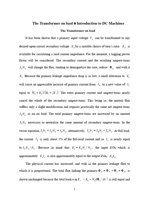
The Transformer on load ﹠Introduction to DC MachinesThe Transformer on loadIt has been shown that a primary input voltage 1V can be transformed to any desired open-circuit secondary voltage 2E by a suitable choice of turn’s ratio. 2E is available for circulating a load current impedance. For the moment, a lagging power factor will be considered. The secondary current and the resulting ampere-turns 22N I will change the flux, tending to demagnetize the core, reduce m Φ and with it 1E . Because the primary leakage impedance drop is so low, a small alteration to 1E will cause an appreciable increase of primary current from 0I to a new value of 1I equal to ()()i jX R E V ++111/. The extra primary current and ampere-turns nearly cancel the whole of the secondary ampere-turns. This being so, the mutual flux suffers only a slight modification and requires practically the same net ampere-turns 10N I as on no load. The total primary ampere-turns are increased by an amount 22N I necessary to neutralize the same amount of secondary ampere-turns. In the vector equation,102211N I N I N I =+; alternatively, 221011N I N I N I -=. At full load, the current 0I is only about 5% of the full-load current and so 1I is nearly equal to 122/N N I . Because in mind that 2121/N N E E =, the input kV A which is approximately 11I E is also approximately equal to the output kV A, 22I E .The physical current has increased, and with in the primary leakage flux to which it is proportional. The total flux linking the primary,111Φ=Φ+Φ=Φm p is shown unchanged because the total back e.m.f., (dt d N E /111Φ-)is still equal andopposite to 1V . However, there has been a redistribution of flux and the mutual component has fallen due to the increase of 1Φ with 1I . Although the change is small, the secondary demand could not be met without a mutual flux and e.m.f. alteration to permit primary current to change. The net flux s Φlinking the secondary winding has been further reduced by the establishment of secondary leakage flux due to 2I , and this opposes m Φ. Although m Φ and 2Φ are indicated separately, they combine to one resultant in the core which will be downwards at the instant shown. Thus the secondary terminal voltage is reduced to dt d N V S /22Φ-= which can be considered in two components, i.e. dt d N dt d N V m //2222Φ-Φ-=or vectorially 2222I jX E V -=. As for the primary, 2Φ is responsible for a substantially constantsecondary leakage inductance 222222/Λ=ΦN i N . It will be noticed that the primary leakage flux is responsible for part of the change in the secondary terminal voltage due to its effects on the mutual flux. The two leakage fluxes are closely related;2Φ, for example, by its demagnetizing action on m Φ has caused the changes on the primary side which led to the establishment of primary leakage flux.If a low enough leading power factor is considered, the total secondary flux and the mutual flux are increased causing the secondary terminal voltage to rise with load. p Φ is unchanged in magnitude from the no load condition since, neglecting resistance, it still has to provide a total back e.m.f. equal to 1V . It is virtually the same as 11Φ, though now produced by the combined effect of primary and secondary ampere-turns. The mutual flux must still change with load to give a change of 1E and permit more primary current to flow. 1E has increased this timebut due to the vector combination with 1V there is still an increase of primary current.Two more points should be made about the figures. Firstly, a unity turns ratio has been assumed for convenience so that '21E E =. Secondly, the physical picture is drawn for a different instant of time from the vector diagrams which show 0=Φm , if the horizontal axis is taken as usual, to be the zero time reference. There are instants in the cycle when primary leakage flux is zero, when the secondary leakage flux is zero, and when primary and secondary leakage flux is zero, and when primary and secondary leakage fluxes are in the same sense.The equivalent circuit already derived for the transformer with the secondary terminals open, can easily be extended to cover the loaded secondary by the addition of the secondary resistance and leakage reactance.Practically all transformers have a turn’s ratio different from unity although such an arrangement is sometimes employed for the purposes of electrically isolating one circuit from another operating at the same voltage. To explain the case where 21N N ≠ the reaction of the secondary will be viewed from the primary winding. The reaction is experienced only in terms of the magnetizing force due to the secondary ampere-turns. There is no way of detecting from the primary side whether 2I is large and 2N small or vice versa, it is the product of current and turns which causes the reaction. Consequently, a secondary winding can be replaced by any number of different equivalent windings and load circuits which will give rise to an identical reaction on the primary .It is clearly convenient to change the secondary winding to an equivalent winding having the same number of turns 1N as the primary.With 2N changes to 1N , since the e.m.f.s are proportional to turns, 2212)/('E N N E = which is the same as 1E .For current, since the reaction ampere turns must be unchanged 1222'''N I N I = must be equal to 22N I .i.e. 2122)/(I N N I =.For impedance, since any secondary voltage V becomes V N N )/(21, and secondary current I becomes I N N )/(12, then any secondary impedance, including load impedance, must become I V N N I V /)/('/'221=. Consequently, 22212)/('R N N R = and 22212)/('X N N X = .If the primary turns are taken as reference turns, the process is called referring to the primary side.There are a few checks which can be made to see if the procedure outlined is valid.For example, the copper loss in the referred secondary winding must be the same as in the original secondary otherwise the primary would have to supply a different loss power.''222R I Must be equal to 222R I . )222122122/()/(N N R N N I ∙∙ does in fact reduce to 222R I . Similarly the stored magnetic energy in the leakage field )2/1(2LI which is proportional to 22'X I will be found to check as ''22X I . The referred secondary 2212221222)/()/(''I E N N I N N E I E kVA =∙==.The argument is sound, though at first it may have seemed suspect. In fact, if the actual secondary winding was removed physically from the core and replaced by the equivalent winding and load circuit designed to give the parameters 1N ,'2R ,'2X and'2I , measurements from the primary terminals would be unable to detect any difference in secondary ampere-turns, kVA demand or copper loss, under normal power frequency operation.There is no point in choosing any basis other than equal turns on primary and referred secondary, but it is sometimes convenient to refer the primary to the secondary winding. In this case, if all the subscript 1’s are interchanged for the subscript 2’s, the necessary referring constants are easily found; e.g. 2'1R R ≈,21'X X ≈; similarly 1'2R R ≈ and 12'X X ≈. The equivalent circuit for the general case where 21N N ≠ except that m r has been added to allow for iron loss and an ideal lossless transformation has been included before the secondary terminals to return '2V to 2V .All calculations of internal voltage and power losses are made before this ideal transformation is applied. The behavior of a transformer as detected at both sets of terminals is the same as the behavior detected at the corresponding terminals of this circuit when the appropriate parameters are inserted. The slightly different representation showing the coils 1N and 2N side by side with a core in between is only used for convenience. On the transformer itself, the coils are, of course, wound round the same core.Very little error is introduced if the magnetizing branch is transferred to the primary terminals, but a few anomalies will arise. For example, the current shown flowing through the primary impedance is no longer the whole of the primary current. The error is quite small since 0I is usually such a small fraction of 1I . Slightly different answers may be obtained to a particular problem depending on whether or not allowance is made for this error. With this simplified circuit, the primary and referred secondary impedances can be added to give:221211)/(Re N N R R += And 221211)/(N N X X Xe +=It should be pointed out that the equivalent circuit as derived here is only valid for normal operation at power frequencies; capacitance effects must be taken into account whenever the rate of change of voltage would give rise to appreciable capacitance currents,dt CdV I c /=. They are important at high voltages and at frequencies much beyond 100 cycles/sec. A further point is not the only possible equivalent circuit even for power frequencies .An alternative , treating the transformer as a three-or four-terminal network, gives rise to a representation which is just as accurate and has some advantages for the circuit engineer who treats all devices as circuit elements with certain transfer properties. The circuit on this basis would have a turns ratio having a phase shift as well as a magnitude change, and the impedances would not be the same as those of the windings. The circuit would not explain the phenomena within the device like the effects of saturation, so for an understanding of internal behavior.There are two ways of looking at the equivalent circuit:(a) viewed from the primary as a sink but the referred load impedance connected across '2V ,or(b) Viewed from the secondary as a source of constant voltage 1V with internal drops due to 1Re and 1Xe . The magnetizing branch is sometimes omitted in this representation and so the circuit reduces to a generator producing a constant voltage 1E (actually equal to 1V ) and having an internal impedance jX R + (actually equal to 11Re jXe +).In either case, the parameters could be referred to the secondary winding and this may save calculation time.The resistances and reactances can be obtained from two simple light load tests.Introduction to DC MachinesDC machines are characterized by their versatility. By means of various combination of shunt, series, and separately excited field windings they can be designed to display a wide variety of volt-ampere or speed-torque characteristics for both dynamic and steady state operation. Because of the ease with which they can be controlled, systems of DC machines are often used in applications requiring a wide range of motor speeds or precise control of motor output.The essential features of a DC machine are shown schematically. The stator has salient poles and is excited by one or more field coils. The air-gap flux distribution created by the field winding is symmetrical about the centerline of the field poles. This axis is called the field axis or direct axis.As we know, the AC voltage generated in each rotating armature coil is converted to DC in the external armature terminals by means of a rotating commutator and stationary brushes to which the armature leads are connected. The commutator-brush combination forms a mechanical rectifier, resulting in a DC armature voltage as well as an armature m.m.f. wave which is fixed in space. The brushes are located so that commutation occurs when the coil sides are in the neutral zone, midway between the field poles. The axis of the armature m.m.f. wave then in 90 electrical degrees from the axis of the field poles, i.e., in the quadrature axis. In the schematic representation the brushes are shown in quadrature axis because this is the position of the coils to which they are connected. The armature m.m.f. wave then is along the brush axis as shown.. (The geometrical position of the brushes in an actual machine is approximately 90 electrical degrees from their position in the schematic diagram because of the shape of the end connections to the commutator.) The magnetic torque and the speed voltage appearing at the brushes areindependent of the spatial waveform of the flux distribution; for convenience we shall continue to assume a sinusoidal flux-density wave in the air gap. The torque can then be found from the magnetic field viewpoint.The torque can be expressed in terms of the interaction of the direct-axis air-gap flux per pole d Φ and the space-fundamental component 1a F of the armature m.m.f. wave . With the brushes in the quadrature axis, the angle between these fields is 90 electrical degrees, and its sine equals unity. For a P pole machine12)2(2a d F P T ϕπ= In which the minus sign has been dropped because the positive direction of the torque can be determined from physical reasoning. The space fundamental 1a F of the saw tooth armature m.m.f. wave is 8/2π times its peak. Substitution in above equation then givesa d a a d a i K i mPC T ϕϕπ==2 Where a i =current in external armature circuit;a C =total number of conductors in armature winding;m =number of parallel paths through winding;AndmPC K a a π2= Is a constant fixed by the design of the winding.The rectified voltage generated in the armature has already been discussed before for an elementary single-coil armature. The effect of distributing the winding in several slots is shown in figure, in which each of the rectified sine waves is thevoltage generated in one of the coils, commutation taking place at the moment when the coil sides are in the neutral zone. The generated voltage as observed from the brushes is the sum of the rectified voltages of all the coils in series between brushes and is shown by the rippling line labeled a e in figure. With a dozen or so commutator segments per pole, the ripple becomes very small and the average generated voltage observed from the brushes equals the sum of the average values of the rectified coil voltages. The rectified voltage a e between brushes, known also as the speed voltage, ism d a m d a a W K W mPC e ϕϕπ==2 Where a K is the design constant. The rectified voltage of a distributed winding has the same average value as that of a concentrated coil. The difference is that the ripple is greatly reduced.From the above equations, with all variable expressed in SI units:m a a Tw i e =This equation simply says that the instantaneous electric power associated with the speed voltage equals the instantaneous mechanical power associated with the magnetic torque, the direction of power flow being determined by whether the machine is acting as a motor or generator.The direct-axis air-gap flux is produced by the combined m.m.f. f f i N ∑ of the field windings, the flux-m.m.f. characteristic being the magnetization curve for the particular iron geometry of the machine. In the magnetization curve, it is assumed that the armature m.m.f. wave is perpendicular to the field axis. It will be necessary to reexamine this assumption later in this chapter, where the effects of saturation are investigated more thoroughly. Because the armature e.m.f. is proportional to fluxtimes speed, it is usually more convenient to express the magnetization curve in terms of the armature e.m.f. 0a e at a constant speed 0m w . The voltage a e for a given flux at any other speed m w is proportional to the speed,i.e.00a m m a e w w e Figure shows the magnetization curve with only one field winding excited. This curve can easily be obtained by test methods, no knowledge of any design details being required.Over a fairly wide range of excitation the reluctance of the iron is negligible compared with that of the air gap. In this region the flux is linearly proportional to the total m.m.f. of the field windings, the constant of proportionality being the direct-axis air-gap permeance.The outstanding advantages of DC machines arise from the wide variety of operating characteristics which can be obtained by selection of the method of excitation of the field windings. The field windings may be separately excited from an external DC source, or they may be self-excited; i.e., the machine may supply its own excitation. The method of excitation profoundly influences not only the steady-state characteristics, but also the dynamic behavior of the machine in control systems.The connection diagram of a separately excited generator is given. The required field current is a very small fraction of the rated armature current. A small amount of power in the field circuit may control a relatively large amount of power in the armature circuit; i.e., the generator is a power amplifier. Separately excited generators are often used in feedback control systems when control of the armature voltage over a wide range is required. The field windings of self-excited generators may be supplied in three different ways. The field may be connected in series withthe armature, resulting in a shunt generator, or the field may be in two sections, one of which is connected in series and the other in shunt with the armature, resulting in a compound generator. With self-excited generators residual magnetism must be present in the machine iron to get the self-excitation process started.In the typical steady-state volt-ampere characteristics, constant-speed prime movers being assumed. The relation between the steady-state generated e.m.f. a E and the terminal voltage t V isa a a t R I E V -=Where a I the armature is current output and a R is the armature circuit resistance. In a generator, a E is large than t V ; and the electromagnetic torque T is a counter torque opposing rotation.The terminal voltage of a separately excited generator decreases slightly with increase in the load current, principally because of the voltage drop in the armature resistance. The field current of a series generator is the same as the load current, so that the air-gap flux and hence the voltage vary widely with load. As a consequence, series generators are not often used. The voltage of shunt generators drops off somewhat with load. Compound generators are normally connected so that the m.m.f. of the series winding aids that of the shunt winding. The advantage is that through the action of the series winding the flux per pole can increase with load, resulting in a voltage output which is nearly constant. Usually, shunt winding contains many turns of comparatively heavy conductor because it must carry the full armature current of the machine. The voltage of both shunt and compound generators can be controlled over reasonable limits by means of rheostats in the shunt field. Any of the methods of excitation used for generators can also be used for motors. In the typical steady-state speed-torque characteristics, it is assumed that the motorterminals are supplied from a constant-voltage source. In a motor the relation between the e.m.f. a E generated in the armature and the terminal voltage t V isa a a t R I E V +=Where a I is now the armature current input. The generated e.m.f. a E is now smaller than the terminal voltage t V , the armature current is in the opposite direction to that in a motor, and the electromagnetic torque is in the direction to sustain rotation of the armature.In shunt and separately excited motors the field flux is nearly constant. Consequently, increased torque must be accompanied by a very nearly proportional increase in armature current and hence by a small decrease in counter e.m.f. to allow this increased current through the small armature resistance. Since counter e.m.f. is determined by flux and speed, the speed must drop slightly. Like the squirrel-cage induction motor, the shunt motor is substantially a constant-speed motor having about 5 percent drop in speed from no load to full load. Starting torque and maximum torque are limited by the armature current that can be commutated successfully.An outstanding advantage of the shunt motor is ease of speed control. With a rheostat in the shunt-field circuit, the field current and flux per pole can be varied at will, and variation of flux causes the inverse variation of speed to maintain counter e.m.f. approximately equal to the impressed terminal voltage. A maximum speed range of about 4 or 5 to 1 can be obtained by this method, the limitation again being commutating conditions. By variation of the impressed armature voltage, very wide speed ranges can be obtained.In the series motor, increase in load is accompanied by increase in the armature current and m.m.f. and the stator field flux (provided the iron is not completelysaturated). Because flux increases with load, speed must drop in order to maintain the balance between impressed voltage and counter e.m.f.; moreover, the increase in armature current caused by increased torque is smaller than in the shunt motor because of the increased flux. The series motor is therefore a varying-speed motor with a markedly drooping speed-load characteristic. For applications requiring heavy torque overloads, this characteristic is particularly advantageous because the corresponding power overloads are held to more reasonable values by the associated speed drops. Very favorable starting characteristics also result from the increase in flux with increased armature current.In the compound motor the series field may be connected either cumulatively, so that its.m.m.f.adds to that of the shunt field, or differentially, so that it opposes. The differential connection is very rarely used. A cumulatively compounded motor has speed-load characteristic intermediate between those of a shunt and a series motor, the drop of speed with load depending on the relative number of ampere-turns in the shunt and series fields. It does not have the disadvantage of very high light-load speed associated with a series motor, but it retains to a considerable degree the advantages of series excitation.The application advantages of DC machines lie in the variety of performance characteristics offered by the possibilities of shunt, series, and compound excitation. Some of these characteristics have been touched upon briefly in this article. Still greater possibilities exist if additional sets of brushes are added so that other voltages can be obtained from the commutator. Thus the versatility of DC machine systems and their adaptability to control, both manual and automatic, are their outstanding features.负载运行的变压器及直流电机导论负载运行的变压器通过选择合适的匝数比,一次侧输入电压1V 可任意转换成所希望的二次侧开路电压2E 。
外文原文:TRANSFORMERTransformers come in many sizes. Some power transformers are as big as a house. Electronic transformers, on the other hand, can be as small as a cube of sugar. All transformers have at least one coil. Most have two although they may have many more.The usual purpose of transformers is to change the level of voltage. But sometimes they are used to isolate a load from the power source.TYPES OF TRANSFORMERSStandard power transformers have two coils. These coils are labeled PRIMARY and SECONDARY. The primary coil is the one connected to the source. The secondary is the one connected to the load. There is to no electrical connection between the primary and secondary. The secondary gets its voltage by induction.The only place where you will see a STEP-UP transformer is at the generating station. Typically, electricity is generated at 13,800 volts. It is stepped down to distribution levels, around 15,000 volts. Large substation transformers have cooling fins to keep them from overheating. Other transformers are located near points where the electric power is used.TRANSFORMER CONSTRUCTIONThe coils of a transformer are electrically insulated from each other. There is a magnetic link, however. The two coils are wound on the same core. Current in the primary magnetizes the core. This produces a magnetic field in the core. The core field then affects current in both primary and secondary.There are two main designs for cores:1.The CORE type has the core inside the windings.2.The SHELL type has the core outside.Smaller power transformers are usually of the core type. The very large transformers are of the shell type. There is no difference in their operation, however.Coils are wound with copper wire. The resistance is kept as low as possible keep losses low.IDEALIZED TRANSFORMERSTransformers are very efficient. The losses are often less than 3 percent. This allows us to assume that they are perfect in many computations.Perfect means that the wire has no resistance. It also means that there are no power losses in the core.Further, we assume that there is no flux leakage. That is, all of the magnetic flux links all of the turns on each coil.EXCITATION CURRENTTo get an idea of just how small the losses are, we can take a look at the EXCITATION CURRENT. Assume that nothing is connected to the secondary. If you apply rated voltage to the primary, a small current flows. Typically, this excitation current is less than 3 percent of rated current.Excitation current is made up of two part is in phase with the voltage. This is the current that supplies the power lost in the core. Core losses are due to EDDY CURRENTS and HYSTERESIS.Eddy currents circulating in the core result from induction. The core is, after all, a conductor within a changing magnetic field.Hysteresis loss is caused by the energy used in lining up magneticdomains in the core. The alignment goes on continuously, first in one direction, then in the other.The other part of the excitation current magnetizes the core. It is this magnetizing current that supplies the “shuttle power”. Shuttle power stored in the magnetic field and returned to the source twice each cycle. Magnetizing current is quadrature (90 degrees out of phase) with the applied voltage.1. INTRODUCTIONThe high-voltage transmission was need for the case electrical power is to be provided at considerable distance from a generating station. At some point this high voltage must be reduced, because ultimately is must supply a load. The transformer makes it possible for various parts of a power system to operate at different voltage levels. In this paper we discuss power transformer principles and applications.2. TOW-WINDING TRANSFORMERSA transformer in its simplest form consists of two stationary coils coupled by a mutual magnetic flux. The coils are said to be mutually coupled because they link a common flux.In power applications, laminated steel core transformers (to which this paper is restricted) are used. Transformers are efficient because the rotational losses normally associated with rotating machine are absent, so relatively little power is lost when transforming power from one voltage level to another. Typical efficiencies are in the range 92 to 99%, the higher values applying to the larger power transformers.The current flowing in the coil connected to the ac source is called the primary winding or simply the primary. It sets up the flux φ in thecore, which varies periodically both in magnitude and direction. The flux links the second coil, called the secondary winding or simply secondary. The flux is changing; therefore, it induces a voltage in the secondary by electromagnetic induction in accordance with Lenz’s law. Thus the primary receives its power from the source while the secondary supplies this power to the load. This action is known as transformer action.3. TRANSFORMER PRINCIPLESWhen a sinusoidal voltage Vpis applied to the primary with the secondary open-circuited, there will be no energy transfer. Theimpressed voltage causes a small current Iθto flow in the primary winding. This no-load current has two functions: (1) it produces the magnetic flux in the core, which varies sinusoidally between zero and φm, whereφmis the maximum value of the core flux; and (2) it provides a component to account for the hysteresis and eddy current losses in the core. There combined losses are normally referred to as the core losses.The no-load current Iθis usually few percent of the rated full-load current of the transformer (about 2 to 5%). Since at no-load the primary winding acts as a large reactance due to the iron core, the no-load current will lag the primary voltage by nearly 90º. It is readily seenthat the current component Im = Isinθ, called the magnetizing current,is 90º in phase behind the primary voltage VP. It is this component thatsets up the flux in the core; φ is therefore in phase with Im.The second component, Ie =Isinθ, is in phase with the primaryvoltage. It is the current component that supplies the core losses. The phasor sum of these two components represents the no-load current, orI 0 = Im+ IeIt should be noted that the no-load current is distortes andnonsinusoidal. This is the result of the nonlinear behavior of the core material.If it is assumed that there are no other losses in the transformer, the induced voltage In the primary, E p and that in the secondary, E s canbe shown. Since the magnetic flux set up by the primary winding ,there will be an induced EMF E in the secondary winding in accordance with Faraday’s law, namely, E=NΔφ/Δt. This same flux also links the primary itself, inducing in it an EMF, E p . As discussed earlier, theinduced voltage must lag the flux by 90º, therefore, they are 180º out of phase with the applied voltage. Since no current flows in the secondary winding, E s =V s . The no-load primary current I 0 is small, a few percentof full-load current. Thus the voltage in the primary is small and V p is nearly equal to E p . The primary voltage and the resulting flux aresinusoidal; thus the induced quantities E p and E s vary as a sine function.The average value of the induced voltage given byE avg = turns× change in flux in a given time given time which is Faraday’s law applied to a f inite time interval. It followsthatE avg = N21/(2)m f = 4fNφm which N is the number of turns on the winding. Form ac circuit theory, the effective or root-mean-square (rms) voltage for a sine wave is 1.11 times the average voltage; thusE = 4.44fNφmSince the same flux links with the primary and secondary windings, the voltage per turn in each winding is the same. HenceE p = 4.44fN p φmandE s = 4.44fN s φmwhere E p and Es are the number of turn on the primary and secondarywindings, respectively. The ratio of primary to secondary induced voltage is called the transformation ratio. Denoting this ratio by a, it is seen that a = p sE E = p s N N Assume that the output power of a transformer equals its input power, not a bad sumption in practice considering the high efficiencies. What we really are saying is that we are dealing with an ideal transformer; that is, it has no losses. ThusP m = P outorV p I p × primary PF = V s I s × secondary PFwhere PF is the power factor. For the above-stated assumption it means that the power factor on primary and secondary sides are equal; thereforeV p I p = V s I s from which is obtainedp s V V = p s I I ≌ p sE E ≌ a It shows that as an approximation the terminal voltage ratio equals the turns ratio. The primary and secondary current, on the other hand, are inversely related to the turns ratio. The turns ratio gives a measure of how much the secondary voltage is raised or lowered in relation to the primary voltage. To calculate the voltage regulation, we need more information.The ratio of the terminal voltage varies somewhat depending on the load and its power factor. In practice, the transformation ratio is obtained from the nameplate data, which list the primary and secondary voltage under full-load condition.When the secondary voltage V s is reduced compared to the primaryvoltage, the transformation is said to be a step-down transformer: conversely, if this voltage is raised, it is called a step-up transformer. In a step-down transformer the transformation ratio a is greater than unity (a>1.0), while for a step-up transformer it is smaller than unity (a<1.0). In the event that a=1, the transformer secondary voltage equals the primary voltage. This is a special type of transformer used in instances where electrical isolation is required between the primary and secondary circuit while maintaining the same voltage level. Therefore, this transformer is generally knows as an isolation transformer.As is apparent, it is the magnetic flux in the core that forms the connecting link between primary and secondary circuit. In section 4 it is shown how the primary winding current adjusts itself to the secondary load current when the transformer supplies a load.Looking into the transformer terminals from the source, an impedanceis seen which by definition equals V p / I p . From p s V V = p s I I ≌ p sE E ≌ a , we have V p = aV s and I p = I s /a.In terms of V s and I s the ratio of V p to I p isp p V I = /s s aV I a = 2s sa V I But V s / I s is the load impedance Z L thus we can say thatZ m (primary) = a 2Z LThis equation tells us that when an impedance is connected to the secondary side, it appears from the source as an impedance having a magnitude that is a 2 times its actual value. We say that the load impedance is reflected or referred to the primary. It is this property of transformers that is used in impedance-matching applications.4. TRANSFORMERS UNDER LOADThe primary and secondary voltages shown have similar polarities,as indicated by the “dot-making” convention. The dots near the upperends of the windings have the same meaning as in circuit theory; the marked terminals have the same polarity. Thus when a load is connected to the secondary, the instantaneous load current is in the direction shown. In other words, the polarity markings signify that when positive current enters both windings at the marked terminals, the MMFs of the two windings add.Since the secondary voltage depends on the core flux φ, it mustbe clear that the flux should not change appreciably if Esis to remain essentially constant under normal loading conditions. With the loadconnected, a current Iswill flow in the secondary circuit, because theinduced EMF Eswill act as a voltage source. The secondary currentproduces an MMF Ns Isthat creates a flux. This flux has such a directionthat at any instant in time it opposes the main flux that created it in the first place. Of course, this is Lenz’s law in action. Thus the MMFrepresented by Ns Istends to reduce the core flux φ. This means thatthe flux linking the primary winding reduces and consequently the primaryinduced voltage Ep, This reduction in induced voltage causes a greater difference between the impressed voltage and the counter induced EMF, thereby allowing more current to flow in the primary. The fact thatprimary current Ipincreases means that the two conditions stated earlier are fulfilled: (1) the power input increases to match the power output, and (2) the primary MMF increases to offset the tendency of the secondary MMF to reduce the flux.In general, it will be found that the transformer reacts almost instantaneously to keep the resultant core flux essentially constant.Moreover, the core flux φdrops very slightly between n o load and fullload (about 1 to 3%), a necessary condition if Epis to fall sufficientlyto allow an increase in Ip.On the primary side, Ip’ is the current that flows in the primaryto balance the demagnetizing effect of Is . Its MMF NpIp’ sets up a fluxlinking the primary only. Since the core flux φ0 remains constant. Imust be the same current that energizes the transformer at no load. Theprimary current Ip is therefore the sum of the current Ip’ and I.Because the no-load current is relatively small, it is correct to assume that the primary ampere-turns equal the secondary ampere-turns, since it is under this condition that the core flux is essentially constant. Thus we will assume that Iis negligible, as it is only a small component of the full-load current.When a current flows in the secondary winding, the resulting MMF (Ns Is )creates a separate flux, apart from the flux φ0 produced by I, whichlinks the secondary winding only. This flux does no link with the primary winding and is therefore not a mutual flux.In addition, the load current that flows through the primary winding creates a flux that links with the primary winding only; it is called the primary leakage flux. The secondary- leakage flux gives rise to an induced voltage that is not counter balanced by an equivalent induced voltage in the primary. Similarly, the voltage induced in the primary is not counterbalanced in the secondary winding. Consequently, these two induced voltages behave like voltage drops, generally called leakage reactance voltage drops. Furthermore, each winding has some resistance, which produces a resistive voltage drop. When taken into account, these additional voltage drops would complete the equivalent circuit diagram of a practical transformer. Note that the magnetizing branch is shown in this circuit, which for our purposes will be disregarded. This follows our earlier assumption that the no-load current is assumed negligiblein our calculations. This is further justified in that it is rarelynecessary to predict transformer performance to such accuracies. Sincethe voltage drops are all directly proportional to the load current, it means that at no-load conditions there will be no voltage drops in eitherwinding.The power transformer is a major power system component that permits economical power transmission with high efficiency and lowseries-voltage drops. Since electric power is proportional to theproduct of voltage and current, low current levels (and therefore low I2 losses and low IZ voltage drops) can be maintained for given power Rlevels via high voltages. Power transformers transform ac voltage andcurrent to optimum levels for generation, transmission, distribution,and utilization of electric power.The development in 1885 by William Stanley of a commercially practicaltransformer was what made ac power systems more attractive than dc powersystems. The ac system with a transformer overcame voltage problemsencountered in dc systems with a transformer overcame voltage problemsencountered in dc systems as load levels and transmission distancesincreased. Today’s modern power transformers have nearly 100%efficiency, with ratings up to and beyond 1300 MVA.In this chapter, we review basic transformers theory and developequivalent circuits for practical transformers operating undersinusoidal-steady-state conditions. We look at models of single-phasetwo-winding, three-phase two-winding, and three-phase three-windingtransformers, as well as auto-transformers and regulating transformers.Also, the per-unit system, which simplifies power system analysis byeliminating the ideal transformer winding in transformers equivalentcircuits, is introduced in this chapter and used throughout the remainderof the text.How Electric Utilities Buy Quality When They Buy TransformersBecause transformers are passive devices with few moving parts, it is difficult to evaluate the quality of one over another. But today, when the lifetime cost of transformer losses far exceeds the initial transformer purchase price and a significant percentage of transformer purchases is to replace units that have failed in service, utilities need a mechanism to weigh one manufacturer’s offering against another’s –often well before the transformer is actually built .Power and distribution transformers present entirely different problems to the purchasing engineers charged with evaluating quality. Power transformers are generally custom-built and today they are often very different from any transformers should be evaluated according to a wide range of quality factors, each of which has a different importance or weight, depending on the purchasing utility.In contrast, distribution transformers are purchased in bulk and, provided detailed failure records are kept, the quality can be rather easily determined from computerized statistical programs.LOW LOSSES MEAN HIGH QUALITYOne factor in the engineer’s favor is that high-quality transformers are also low-loss transformers. In a sense, the cost of high quality is automatically paid for in the first few years of transformer life by reduced losses. To this benefit is added the fact that the lifetime of a transformer built today will actually be significantly longer than that of a transformer built only a few years ago.Losses are divided into load and no-load losses and various formulas and/or computer programs are available to evaluate their lifetime impact. When individual utilities plug their cost factors into the formulas, thelifetime impacts they calculate vary widely. For example, the ratio of estimated costs of no-load to load losses can vary by a factor as much as 10 to one. The relative cost of load and no-load losses can also vary from year to year as regulatory pressures push utility management to emphasize different needs.Noise is becoming an increasingly important factor in transformer selection. Again, this factor varies widely from utility to utility. The greatest need for a low-noise transformer is felt by utilities in highly developed areas where substations must be located close to residential neighborhoods.Transformer noise is generated from three sources: (1) the magneto strictive deformation of the core, (2) aerodynamic noise produced by cooling fans, (3) the mechanical and flow noise from the oil-circulating pumps. The radiated core noise, consisting of a 120-Hz tone, is the most difficult to reduce and is also the noise that generates the transformer.Fortunately, improved core-construction techniques and lower-loss core steel both tend to reduction in core noise is needed, it can only be achieved by increasing the cross-sectional area of the core to reduce the flux density. This design change increases the construction cost of the transformer and decreases the core losses. However, a point of diminishing returns is reached at which the cost of increasing core size outweighs the savings in reduced losses.Installation costs are significant because a power transformer must generally be delivered partially disassembled and without oil in the tank. Today, the trend is for the manufacturer to assemble and fill the transformer on site, rather than leave it to the utility. This provides assurance that the transformer is correctly installed and minimizes the cost of lost parts, misunderstanding, etc.Manufacturing facilities provide a key indication of the product quality. Most utilities use plant visits as the first step in their evaluation process. Facility review should include the manufacturer’s quality-assurance program, in-service and test reliability records, contract administration and order support, and technical strength.Coating systems, especially for pad-mount transformers, are becoming increasingly important since the life of the transformer tank may be the limiting factor in transformer life. The problem of evaluating and comparing coating systems on pad-mount transformers from different manufacturers was eliminated with the introduction of ANSI Standard C57.12.28-1988. This is a functional standard that does not dictate to manufacturers now they should coat transformers, but prescribes a series of tests that the coating must withstand to meet the standard. A companion standard, C57.12.31 for poletop transformers, is now under development.Tests prescribed by the standards include: Scratching to bare metal and exposing to salt spray for 1500 hours; cross-hatch scratching to check for adhesion, humidity exposure at 113℃, impact of 160 in.-1b with no paint chipping , oil and ultraviolet resistance, and 3000 cycles of abrasion resistance.In response to this standard, most manufacturers have revamped or rebuilt their painting processes--from surface preparation through application of primers, to finished coating systems. The most advanced painting processes now use electrodeposition methods—either as a dip process or with paint applied as dry power. These processes not only ensure a uniform coating system to every part of the transformer tank out also, because they eliminate traditional solvent-based paints, more easily meet the Clean Air Act Amendments of 1990.Hard evaluation factors are set down in the purchaser’s technicalspecifications, which form the primary document to ensure that all suppliers’products meet a minimum standard. Technical specifications generally include an evaluation formula for no-load and load losses, price, noise level, and delivery date. Technical assistance during installation, warranty assistance, and the extent of warranty are additional hard evaluation factors.Soft factors do not have a precise monetary value, but also may be important in comparing suppliers’ bids. The [following] list suggests soft factors for buyers to include in a transformer-purchase decision. While they do not have a direct dollar value, it is valuable to assign a fixed dollar value or a percentage of bid value to these factors so that they can be used in comparing suppliers’ bids. A well-written specification places all potential suppliers on an equal footing.SOFT FACTORS THAT SHOULD INFLUENCE CHOICE OF SUPPLIERWide choice of designsComputer-aided design proceduresR&D directed at product improvementParticipation in long-term R&D projects through industry groups Clean-room assembly facilitiesAvailability of spare and replacement partsWide range of field servicesApplication assistance/coordinationOngoing communication with usersTony Hartfield, ABB Power T&D Co., Power Transformer Div., St. Louis, Missouri, says it is important to review technical specifications in detail with prospective suppliers before a request for bids is issued. “We attempt to resolve ambiguous terms such as ‘substantial,’ ‘long-lasting,’ or ‘equal-to,’ and replace them with functionalrequirements that clearly define what must be supplied.“Many times, items are added to a specification to prevent recurrence of past problems. These can be counterproductive, particularly if the technology has advanced to a point where the source of the problem has been eliminated.”GOOD IN-SERVICE RECORDS VITALDistribution transformers are purchased in large quantities under very competitive conditions where a unit-price change of a few cents can affect the choice of supplier. As a result, the most sophisticated programs used to guide purchasing policy are based on statistical records of units in service.One example of a systematic failure-analysis program is that conducted by Wisconsin Public Service Corp. (Electrical World, September 1991, p 73). All transformers purchased by the utility since the mid 1980s and all transformer failures are entered into a computerized record-keeping system. Failure rates and equivalent costs are calculated for each manufacturer on a 4-year rolling window. According to Senior Standards Engineer Michael Radke, the system has substantially reduced failure rates, improved communications with transformer vendors, reduced costs, and reduced outages. The system has even helped some manufacturers to reduce failure rates.Georgia Power Co.’s vendor evaluation program has been in place for about 5 years. This program looks at supplier and product separately, judging each according to pre-established criteria. The scores for each criterion are weighted and the over-all score used to calculate a numerical multiplier, which is applied to initial bid price. David McClure, research manager, quality and support, explains that the program involves four departments: engineering, materials, qualityassurance, and procurement. Each department is responsible for a portion of the evaluation and the results from each are entered into a computer program.The evaluation involves objective and subjective factors. Compliance, for example, can be measured objectively, but customer service must be evaluated subjectively. Even so, reviewers follow a well-defined procedure to determine scores for each factor. This approach ensures that ratings are applied consistently to each vendor.Public Service Co. of Colorado (PSC) uses a numerical multiplier that is applied to the bid price. The multiplier incorporates several factors—including historical failure rate, delivery, and quality. Of these factors, historical failure rate is by far the most important, accounting for more than half of the multiplier penalty. For example, the average multiplier for pole-mounted transformers adds 6.3%, of which failure rate accounts for 4.9%; the average multiplier for single-phase pad-mount transformers adds 5.3%, of which failure rate accounts for 3.6%.Failure rate is calculated using a computer program supplied by General Electric Co., Transformer Business Dept, Hickory, North Carolina. It is based on failures of transformers purchased in the last 10 years. The cost of failure includes the cost of a replacement unit and the costs of changeout and downtime.A delivery penalty is calculated by PSC, based on the difference in weeks between promised and actual delivery dates. Significantly, this penalty is calculated equally for early as for late delivery. Early delivery is considered disruptive. John Ainscough, senior engineer, automation analysis and research, reports that his department is planning to modify this factor to encourage both short lead-times andon-time delivery. Currently, the delivery factor does not incorporate the supplier’s manufacturing cycle time.PSC’ s quality factor is based on the percentage of an order that must be repaired or returned to the manufacturer; the accuracy with which products conform to the original specifications, including losses and impedance; and the number of days required to resolve complaints and warranty claims. Responsiveness to complaints is considered a soft evaluation factor and the number of days needed to resolve a complaint is a way of quantifying this factor. The utility is exploring ways to quantify other soft factors in the evaluation process.According to Ainscough, the rating system in use at PSC seems to be effective for consistently selecting high-quality vendors and screening out those that offer low bids at the expense of product quality.Another software program designed to help purchasers select the best available distribution transformer is a Lotus-compatible worksheet for evaluating distribution transformers offered by ABB Power T&D Co. The worksheet adjusts criteria for reliability, quality, delivery/availability, and support. The lower the value factor, the lower is the effective first cost of the transformer. To the adjusted first cost is added the cost of losses, yielding a life-cycle cost for the transformer.Suggested weightings, based on surveys of utilities, are provided for each critertion, but users can easily modify these criteria in light of their own experience and needs. According to ABB’s Dorman Whitley, this ensures that the worksheet does not favor any one manufacturer. Users can also incorporate soft criteria (such as supplier’s long-term commitment to the industry, or level of investment in R&D).LOSSES INFLUENCE RELIABILITY。
变压器常用术语TECHNICAL TERMS COMMONLYUSED FOR TRANSFORMERPART 1 产品名称及类型1.1 电力变压器Power transformer1.2 芯式变压器core type transformer 内铁式变压器core-form transformer1.3 壳式变压器shell-form transformer 外铁式变压器shell-form transformer1.4 密封式变压器sealed transformer1.5 有载调压电力变压器power transformer with OLTC1.6 无载调压电力变压器power transformer with off-circuit tap-changer 1.28 油浸式变压器oil-immersed type transformer1.29 浸难燃油变压器noninflammable medium impregnated transformer1.30 干式变压器dry type transformer1.31 树脂浇注式变压器resin-casting type transformer1.32 H 级绝缘变压器transformer with H class insulation1.33 气体绝缘变压器gas insulated transformer1.34 电炉变压器furnace transformer1.35 整流变压器rectifier transformer1.36 列车牵引变压器traction transformer, locomotive transformer1.7 配电变压器1.8 自耦变压器distribution transformer auto-transformer1.9 联络变压器interconnecting transformer 1.10 升压变压器step-up transformer1.11 降压变压器step-down transformer1.12 增压变压器booster transformer 串联变压器1.13 发电机变压器generator transformer1.14 电站用变压器substation transformer 1.15 交流变压器converter transformer1.16 分裂变压器split-winding type 1.37 矿用变压器mining transformer 1.38 防爆变压器explosion-proof transformer flame-proof transformer 1.39 隔离变压器isolation transformertransformer1.17 厂用变压器power plant transformer 1.18 所用变压器electric substation 1.40 试验变压器testing transformer 1.41 串级式试验变压器cascade testing transformer串联变压器增压变压器灯丝变压器电焊变压器钎焊变压器船用变压器起动自1.421.431.441.451.46transformer1.19 单相变压器1.20 三相变压器1.21 多相变压器single-phase transformerthree-phase transformerpolyphase transformer1.471.48autotransformer起动变压器移动变压器1.491.501.22 单相变压器组成的三相组three-phase banks with separate single-phase transformer 1.51 1.52 1.531.23 三相接地变压器transformerthree-phase earthing1.24 三线圈变压器transformer1.25 两线圈变压器transformer1.26 双线圈变压器transformer1.27 多线圈变压器transformerthree-windingtwo-windingdouble-windingmulti-windingseries transformerbooster transformerfilament transformerwelding transformer brazingtransformer marinetransformer 耦变压器startingstarting transformermovable substation移动式movable type 成套变电站complete substation 全自动保护单相变压器completeself-protected single-phase transformer(CSP)1.54 互感器instrument transformer1.55 测量用互感器measurementcurrent/voltage TR1.56 保护用互感器protectivecurrent/voltage transformer1.57 电流互感器current transformer (CT )1.58 电压互感器voltage transformerpotential transformer(PT)1.59 全绝缘电流互感器fully insulatedcurrent transformer1.60 母线式电流互感器bus-type current transformer1.61 绕线式电流互感器wound primary type current transformer1.62 瓷箱式电流互感器porcelain type current transformer1.63 套管用电流互感器bushing-type current transformer1.64 电容式电流互感器capacitor typecurrent transformer1.65 支持式电流互感器support-type current transformer1.66 倒立式电流互感器reverse type current transformer1.67 塑料浇注式电流互感器cast resin current transformer1.68 钳式电流互感器split-core type current transformer1.69 速饱和电流互感器rapid-saturable current transformer1.70 串级式电流互感器cascade-type current transformer1.71 剩余电流互感器residual current transformer1.72 电容式电压互感器capacitor type voltage transformer1.73 接地电压互感器earthed voltage transformer1.74 不接地电压互感器unearthed voltage transformer1.75 组合式互感器combined instrument transformer1.76 剩余电压互感器residual voltage transformer1.77 移圈调压器moving-coil voltage transformer1.78 动线圈moving winding1.79 自耦调压器autoformer regulator1.80 接触调压器variac1.81 感应调压器induction voltage regulator 1.82 磁饱和调压器magnetic saturationvoltage regulator1.83 电抗器reactor1.84 并联电抗器shunt reactor1.85 串联电抗器series reactor iron core reactor air core reactor concrete(cement) reactor 1.90 三相中性点接地电抗器three-phase neutral reactor1.92 单相中性点接地电抗器single-phase neutral earthing reactor1.93 起动电抗器starting reactor1.94 平衡电抗器smoothing /interphase reactor1.95 调幅电抗器modulation reactor1.96 消弧电抗器arc-suppression reactor1.97 消弧线圈arc-suppression coil1.98 阻波器,阻波线圈wave trap coil1.99 镇流器ballast1.100 密闭式sealed type1.101 包封式enclosed type1.102 户外式outdoor type1.103 户内式indoor type1.104 柱上式pole mounting type1.105 移动式movable type1.106 列车式trailer mounted type1.107 自冷natural cooling (ONAN)1.108 风冷forced-air cooling (ONAF)1.109 强油风冷forced-oil forced-air cooling(ONAF)1.110 强油水冷forced-oil forced-water cooling (ONWF)1.111 强油导向冷却forced-directed oil cooling (OFAN)1.112 强油导向风冷却forced-directed forced-air oil cooling(ODAF)1.113 恒磁通调压constant flux voltage variation(CFVV)1.114 变磁通调压variable flux voltage variation(VFVV)1.115 混合调压combined voltage variation(CbVV)PART2 基础词汇1.86 饱和电抗器1.87 铁心电抗器1.88 空心电抗器1.89 水泥电抗器saturable reactor2.1 千瓦kilowatt(kw) 2.2 兆瓦megawatt(MW) 2.3 京瓦gigawatt(GW) 2.4 千伏kilovolt(kV)symbol of product type of productrated voltage rated power rated current连 接 组 标 号connectionsymbol,impedance voltage rated frequency no-load losseddy-current loss hysteresis loss no-load current exciting current load loss 损 耗 additional losses,杂散损耗 stray losses 总损耗total losses 损耗比 loss ratio 冷却方式type of cooling 介质损耗 dielectric loss 介损角正切值 loss tangent 电压组合 voltage combination 电抗电压 reactance voltage 额定电压比 rated voltage ratio 电阻电压 resistance voltage 电压调整率 voltage regulation 相位差 phase displacement 相位差 zero-sequence impedance short-circuit impedance flux density current density 安匝数 number of ampere-turns轴向漏磁通 axial leakage flux 2.47 径向漏磁通 radial leakage flux2.48 循环电流 circulating current 2.49 热点 hot spot2.50 最热点 hottest spot 2.51 局部过热 local overheat 2.52 有功输出 active output 2.53 满容量分接 fully-power tapping 2.54 额定级电压 rated step voltage 2.55 最大额定电压 maximum rated voltage 2.56最 大 额 定 电 流 maximum ratedthrough-current2.57 绕 组 额 定 电 压 rated voltage of a winding2.58 额定短时电流 rated short time current 2.59 额定短时热电流 rated short thermal current2.60 额 定 连 续 热 电 流 rated continuous current2.61 额定动稳定电流 rated dynamic current 2.62 一次电流 /电压 primary current/voltage 2.63二 次 电 流 / 电 压 secondarycurrent/voltage2.64 实际电流比 actual transformation ratio of a current transformer2.65 实际电压比 actual transformation ratio of a voltage transformer2.66 二 次 极 限 感 应 电 动 势 secondary limiting e.m.f.2.67 互感器的二次回顾路 secondary circuit of CT and PT 2.68 定额 rating2.69 铁心噪声 noise of core 2.70 背境噪声 background noise 2.71 噪声水平 noise level 2.72 声级 sound level2.73 声功率级 sound power level 2.74 声级试验 sound level test2.75 声级测量 sound level measurement 2.76 水平加速度 horizontal acceleration 2.77 垂直加速度 vertical acceleration 2.78 地震 seism, earthquake 2.79 地震烈度 earthquake intensity 2.80 工频 power-frequency 2.81 中频 medium frequency 2.82 高频 high frequency2.5 2.6 千伏安 KVA 兆伏安 MVA 京伏安 GVA千乏 kilovar(kV Ar)兆乏megavar(MV Ar)京乏 gigavar(GV Ar)2.12 2.13 2.14 2.15 2.16 2.17 产品代号产品型号额定电压 额定容量 额定电流 2.18 symbol of connection 2.19 2.20 2.21 2.22 2.23 2.24 2.25 2.26 阻抗电压 额定频率空载损耗 涡流损耗 磁滞损耗 空载电流 激磁电流负载损耗 附加 2.27 supplementary load loss 2.28 2.292.30 2.31 2.32 2.33 2.34 2.35 2.36 2.372.38 2.39 2.41 2.42 2.432.44 2.452.46校 验 phase displacement 2.40 verification零序阻抗 短路阻抗 磁通密度 电流密度2.7 2.8 2.9 2.10 2.11 兆伏 megavolt(MV)京电子伏 giga-electron-volt(GEV)natural frequency of vibrationfrequency response harmonicsmeasurement 2.88 绝缘水平insulation level2.89 绝缘强度insulation strength, dielectric strength2.90 主绝缘main insulation2.91 纵绝缘longitudinal insulation2.92 内绝缘internal insulation2.93 外绝缘external insulation2.94 绝缘配合insulation co-ordination2.95 全绝缘uniform insulation2.96 半绝缘non-uniform insulation2.97 降纸绝缘reduced insulation2.98 中心点neutral point2.99 中心点端子neutral terminal2.100 正常绝缘normal insulation2.101 介电常数dielectric constant2.102 油纸绝缘系统oil-paper insulation system2.103 绝缘电阻insulation resistance2.104 绝缘电阻吸收比absorption ratio of insulation resistance2.105 绝缘击穿insulation breakdown2.106 碳化carbonization2.107 爬电距离creepage distance2.108 沿面放电creeping discharge2.109 放电discharge2.110 局部放电partial discharge2.111 局部放电测量measurement of partial discharge2.112 超声定位ultrasonic location, ultrasonic orientation2.113 破坏性放电disruptive discharge2.114 局部放电起始电压partial discharge inception voltage2.115 局部放电终止电压partial discharge extinction voltage2.116 过电压overvoltage short time overvoltage transient overvoltage switchingovervoltage atmosphericovervoltage2.121 额定耐受电压rated withstand voltage2.122 工频耐受电压power-frequency withstand voltage2.123 感应耐压试验induced overvoltage withstand test2.124 温升试验temperature-rise test2.125 温升temperature rise2.126 突发短路试验short-circuit test2.127 动热稳定thermo-dynamic stability2.128 冲击耐压试验impulse voltage withstand test2.129 雷电冲击耐受电压lightning impulsewithstand voltage2.130 操作冲击耐受电压switching impulsewithstand voltage2.131 雷电冲击lightning impulse2.132 全波雷电冲击full wave lightning impulse2.133 截波雷电冲击chopped wave lightning impulse2.134 操作冲击switching impulse2.135 操作冲击波switch surge, switch impulse2.136 伏秒特性voltage-time characteristics 2.137 截断时间time to chopping2.138 波前时间time to crest2.139 视在波前时间virtual front time2.140 半峰值时间time to half value crest2.141 峰值peak value, crest value2.142 有效值root-mean-square value2.143 标么值per unit value2.144 标称值nominal value2.145 电级electrode2.146 电位梯度potential gradient2.147 等电位,等位equipotential2.148 屏蔽shielding2.149 静电屏蔽electrostatic shielding2.150 磁屏蔽magnetic shielding2.151 静电屏electrostatic screen2.152 静电板electrostatic plate2.153 静电环electrostatic ring2.154 电磁感应electro-magnetic induction 2.155 电磁单元electro-magnetic unit2.83 振荡频率2.84 谐振频率2.85 自振频率2.86 频率响应2.87 谐波测量oscillating frequency resonance frequency2.117 短时过电压2.118 瞬时过电压2.119 操作过电压2.120 大气过电压2.156 有效面effective surface2.157 标准大气条件standard atmosphericcondition2.158 视在电荷apparent charge2.159 体积电阻volume resistance2.160 导电率admittance2.161 电导conductance, conductivity2.162 电晕放电corona discharge2.163 闪络flashover2.164 避雷器surge arrestor2.165 避雷器的残压residual voltage of an arrestor2.166 绝缘材料耐温等级temperature class of insulation2.167 互感器额定负荷rated burden of an instrument transformer2.168 准确级次accuracy class2.169 真值true value2.170 允差tolerance2.171 比值误差校验ratio error verification 2.172 电流误差current error2.173 电压误差voltage error2.174 互感器相角差phase displacement of instrument transformer2.175 复合误差composite error2.176 瞬时特性transient characteristic2.177 瞬时误差transient error2.178 额定仪表保安电流rated instrument security current2.179 二次极限感应电势secondary limitinge.m.f2.180 保安因子security factor2.181 额定准确限值的一次电流rated accuracy limit primary current2.182 误差补偿error compensation2.183 额定电压因子rated voltage factor2.184 准确限值因子accuracy limit factor2.185 开断电流switched current2.186 笛卡尔坐标,直角坐标Cartesian coordinate2.187 极坐标polar coordinate2.188 横坐标abscissa2.189 纵坐标ordinate 2.190 X- 轴X-axis2.191 复数complex number2.192 实数部分real component2.193 虚数部分imaginary component2.194 正数positive number2.195 负数negative number2.196 小数decimal2.197 四舍五入round off2.198 分数fraction2.199 分子numerator2.200 分母denominator2.201 假分数improper fraction2.202 钝角obtuse angle2.203 锐角acute angle2.204 补角supplementary angle2.205 余角complement angle2.206 平行parallel2.207 垂直perpendicular2.208 乘方involution2.209 开方evolution, extraction of root2.210 n 的 5 次方5th power of n2.211 幂exponent, exponential2.212 微分,差动differential, differentiate 2.213 积分,集成integral, integrate2.214 成正比proportio nal to2.215 成反比inversely proportional to2.216 概率probability2.217 归纳法inductive method2.218 外推法extrapolation method2.219 插入法interpolation method2.220 最大似然法maximum likelihood method2.221 图解法graphic method2.222 有限元法finite element method2.223 模拟法simulation method2.224 方波回应step response2.225 迭加电荷superimposed charge2.226 杂散电容stray capacitance2.227 无损探伤non-distractive flaw detection2.228 红外线扫描infrared scanning2.229 计算机辅助设计computer aided design(CAD)2.230 计算机辅助制造computer aided manufacturing(CAM)2.231 计算机辅助试验computer aidedtest(CAT)2.233 近似于approximate( approx)minute(rpm)2.235 速度velocity2.236 加速度acceleration2.237 重力加速度gravitational acceleration 2.238 引力traction2.240 件数pieces2.242 缩写abbreviation2.243 以下简称为hereinafter referred as xxx2.244 常用单位units commonly used2.245 包括缩写including abbreviations2.246 分米decimeter 厘米centimeter2.247 海里knot2.248 码yard2.249 磅pound(1b) 磅/平方英寸pound per square inch(ppsi)2.251 英制热量单位British thermal unit (BTU) 2.252 马力horsepower2.253 压强intensity of pressure2.254 帕斯卡Pascal(Pa)2.255 千帕kpa 兆帕Mpa2.256 粘度viscosity2.257 帕斯卡秒pascal.second2.258 泊poise 厘泊centipoises2.259 焦耳joule(J) 千瓦时kilowatt-hour(kwh)2.260 特斯拉tesla(T) 高斯gaue(Gs)2.261 奥斯特oersted(0e) 库仑coulomb(C) 2.262 微微库Pico-coulomb(PC)2.263 达因dyne2.264 摄氏度Celsius, centigrade( C)2.265 开尔文Kelvin 法拉farad(F)2.266 皮可法拉pico-farad(pF)2.268 立方分米cubic decimeter立方厘米cubic centimeter2.269 桶barrel 石油petroleum2.270 标准国际单位制standard international unit2.271 厘米-克秒单位制CGS unit 2.272 环境设备ambience apparatus2.273 校验calibration2.274 兼容性compatibility2.275 扩散系数diffusion coefficient2.276 故障fault2.277 公顷hectarePART3 典型产品结构3.1 芯式,内铁式core type3.2 壳式,外铁式shell type3.3 铁心core3.4 磁路magnetic circuit3.5 线圈winding, coil3.6 高压线圈HV winding3.7 中压线圈MV winding3.8 低压线圈LV winding3.9 调压线圈tapped winding, regulating winding3.10 高压引线high-voltage leads3.11 中压引线mid-voltage leads3.12 低压引线low-voltage leads3.13 夹件clamping frame3.14 上部夹件upper clamping3.15 下部夹件lower clamping3.16 线圈压紧螺栓winding compressing bolt 3.17 线圈压紧装置winding compressing device3.18 线圈端部绝缘end insulation of winding3.19 器身定位装置positioning device for active-part3.20 定位装置fixing device3.21 铁心垫脚foot-plate of core3.22 垫脚foot-pad3.23 分接引线tapping leads, tap leads3.24 引线支架supporting frame for leads3.25 无励磁分接开关non-excitation tap-changer3.26 无载分接开关off-circuit tap-changer3.27 分接选择器tap selector3.28 有载分接开关on-loadtap-changer(OLTC) on-circuit tap-changer3.29 切换开关diverter switch3.30 选择开关selector switch3.31 转换选择器change-over selector2.234 每分钟转数revolution per3.32 粗选择器coarse tap selector3.33 触头组set of contacts3.34 过度触头transition contacts3.35 过度阻抗transition impedance3.36 有载开关操纵机构operating mechanism of OLTC3.37 驱动机构driving mechanism3.38 电动机构motor drive3.39 垂直转动轴vertical driving shaft 水平转动轴horizontal driving shaft3.40 伞尺轮盒bevel gear box3.41 防雨罩drip-proof cap3.42 联轴节coupling3.43 最大分接maximum tapping 最小分接minimum tapping3.44 额定分接rated tapping, principal tapping3.45 固定分接位置数number of inherent tapping positions 工作分接位置数number of service tapping positions3.46 主分接principal tap, main tap 正分接plus tapping 负分接minus tapping3.47 分接变换操作tap-changer operation tap position indicator tapping voltage of atapping current of atapping power of awinding3.52 分接范围tapping range3.53 分接量tapping quantities3.54 分接因子tapping factor3.55 分接工作能力tapping duty3.56 分接线tapping step3.57 分接线tapping connection3.58 分接引线tapping lead3.59 小车支架及滚轮bogie frame and wheel3.61 箱底tank bottom3.62 箱盖tank cover3.63 箱沿tank rim3.64 垫脚垫块supporting block for foot-pad 3.65 联管接头tube connector3.66 联接法兰connecting flange3.67 加强筋,加强板stiffener3.68 油箱垂直加强铁vertical stiffening channel of tank wall3.69 油箱活门oil sampling valve3.70 放油活门oil drainningvalve3.71 冷却器cooler3.72 集中安装concentrated installation 3.73 集中安装强油循环风冷器concentrated installation of forced-oil circulating air cooler3.74 冷却器进口inlet of cooler冷却器出口outlet of cooler3.75 潜油泵oil-submerged pump3.76 油流继电器oil flow relay3.77 净油器oil filter3.78 虹吸净油器oil siphon filter3.79 散热器radiator3.80 片式散热器panel type radiator3.81 管式散热器tubular radiator3.82 放油塞oil draining plug3.83 放气塞air exhausting plug3.84 蝶阀radiator valve butterfly valve3.85 风扇支架supporting frame for fan motors3.86 风扇及电机fan and motor3.87 风扇接线盒connecting box for fan motors3.88 储油柜conservator3.89 油位计oil-level indicator3.90 气体继电器gas relay, buchholz realy 3.91 皮托继电器pitot relay3.92 储油柜联管elbow joint for conservator 3.93 有载开关用储油柜conservator for OLTC3.94 有载开关用气体继电器gas relay for OLTC3.95 联管tube connector3.96 吸湿器dehydrating breather3.97 铭牌rating plate3.98 温度计thermometer3.98 指示仪表柜cabinet panel for indicating instruments3.99 风扇控制柜cabinet panel for fan motor control3.100 压力释放阀pressure-relief valve3.101 安全气道explosion-proof pope3.102 膨胀器expander3.103 主排气导管main gas-conduit3.104 分支导气管branching gas-conduit3.105 滤油界面tube connector for oil-filter 3.106 温度计座thermometer socket3.107 储油柜支架supporting frame for conservator3.108 高压套管HV bushing3.48 分接位置指示器3.49 线圈分接电压winding3.50 线圈分接电流winding3.51 线圈分接容量3.109 高压套管均压球equipotential shielding for HV bushing3.110 高压零相套管HV neutral bushing, HV bushing phase03.111 中压套管MV bushing3.112 中压零相套管MV neutral bushing,MV bushing phase03.113 低压套管LV bushing3.114 接地套管earthing bushing3.115 极性polarity3.116 极化polarization3.117 高压套管储油柜conservator for HV bushing3.118 相间隔板interphase insulating barrier 3.119 吊攀lifting lug3.120 安装轨道installation rail3.121 相序标志牌designation mark of phase sequence3.122 接地螺栓earthing bolt3.123 视察窗inspection hole3.124 手孔handhole3.125 人孔manhole3.126 MR 有载开关MR OLTC3.127 ABB 有载开关ABB OLTC3.128 伊林有载开关ELIN OLTC3.129 F& 套管F&G bushingPART4 铁心结构4.1 多框式铁心multi-frame type core4.2 三相三柱铁心three-phase three-limb core4.3 三相五柱铁心three-phase five-limb core4.4 卷铁心wound core4.5 冷轧晶粒取向硅钢片cold-rolled grain-oriented silicon sheet steel4.6 晶粒crystalline grain4.7 高导磁硅钢片HI-B silicon sheet steel 4.8 铁心片core lamination4.9 一迭铁心 a lamination stock4.10 铁心迭积图lamination drawing, lamination diagram4.11 迭片lamination4.12 迭片系数lamination factor4.13 空间利用系数space factor4.14 层间绝缘layer insulation 4.15 斜接缝mitring4.16 45°斜接缝45° mitred joint4.17 斜接缝的交错排列方式over-lay arrangement for mitred joints of lamination 4.18 重迭overlap4.19 铁心油通oil-duct of core4.20 铁心气道air ventilating duct of core4.21 阶梯接缝stepped lay joint4.22 对接铁心butt jointed core4.23 渐开线铁心evolute core, involute core 4.24 空气隙air gap4.25 铁心拉板tensile plate of core limb, core drawplate4.26 铁心柱core limb, core lge4.27 轭,铁轭yoke4.28 上轭upper yoke下轭lower yoke旁轭side yoke, return yoke4.29 环氧绑扎带epoxy-bonded bandage4.30 轭拉带yoke tensile belt4.31 铁轭拉带banded band of core yoke4.32 上轭顶梁top jointing beam of upper yoke 4.33 侧梁side beam4.34 夹件clamping frame4.35 铁心夹件core clamps, coreframe4.36 铁轭夹件yoke clamping, yoke clamps 4.37 上夹件upper yoke clamping, upper yoke clamps4.38 下夹件lower yoke clampings, lower yoke clamps4.39 夹件腹板web of yoke clamping4.40 夹件肢板limb of yoke clamping4.41 夹件加强stiffening plate of clamping4.42 压线圈的压钉winding compressing bolt4.43 压钉螺母nut for compressing bolt4.44 弹簧压钉compressing bolt with spring 4.45 油缸压钉compressing bolt with hydraulic damper4.46 线圈支撑架winding supporter4.47 线圈支撑架 winding supporting plate 4.48 垫脚 foot pad 4.49 定位孔 positioning hole4.50 带螺母的定位柱 positioning stud 4.51 拉螺杆 tensile rod5.15 部 分 纠 结 式 线 圈 partial-interleaved winding5.16 插花纠结式线圈 sandwich-interleaved winding5.17 内 屏 连 续 式 线 圈 4.52 夹件夹紧螺杆 yoke clamping bolt 4.53 铁心接地片 core earthing strip 4.54 铁心地屏 4.55 旁轭地屏 4.56 接地屏蔽 earthing screen of code earthing screen of side yoke earthing shield 4.57 铁心窗高 core window height 4.58 中心距 M center line distance M 4.59 铁心中间距 center distance between lombs 4.60 木垫块 4.61 迭片系数 4.62 铁心的级4.63 心 柱 外 接 圆 core leg 4.64 铁心端面 lamination 4.65 木棒 wood padding block laminationfactor stage of lamination stacks circumscribed circle of innershield-continuous winding5.18 插 入 电 容 式 线 圈 capacitor shield winding5.19 高 串 联 电 容 线 圈 high series capacitance winding5.20 双饼式线圈 twin-disk winding 5.21 交 错 式 线 圈 sandwich winding, staggered winding5.22 螺 旋 式 线 圈 helical winding, helix winding5.23 半螺旋式线圈 semi-helical winding4.66 定位板 PART5 线圈结构5.1 圆筒式线圈 5.2 层式线圈 5.3饼式线圈 core surface perpendicular to wood bar, wood rod positioning plate cylindrical winding5.24 单列 螺 旋式 线圈 single-row helicalwinding5.25 双列 螺旋式 线圈 double-row helicalwinding5.26 三列 螺旋式 线圈 three-row helical5.4 单层圆筒式线圈 winding 5.5 双层圆筒式线圈winding 5.6 多层圆筒式线圈 winding 5.7 大型层式 线圈 winding 5.8 分段圆筒式线圈 5.9 分段多层圆筒线圈layer winding disk winding single layer cylindricaldouble layer cylindrical multi-layer cylindrical large size long layer sectional layer winding sectional multi-layer winding5.27 短螺旋式线圈 short helical winding 5.28 螺旋式线 圈引 出端的 固定 terminal fixing for helical winding 5.29 分裂式线圈 split winding 5.30 分段式线圈 sectional winding 5.31 箔式线圈 foil winding5.32 全 绝 缘 线 圈 uniformly insulated winding5.33 分 级 绝 缘 线 圈 gradedly insulated winding, winding with non-uniform insulation 5.34 第三线圈 tertiary winding 5.35 高压线圈 high-voltage winding 5.36 中 压 线 圈 mid-voltage winding, intermediate voltage windingwinding5.10 连续式线圈 continuous winding 5.11 半 连 续 式 线 圈 semi-continuous 5.37 低压线圈 5.38 调压线圈 windinglow-voltage winding regulating winding,tappedwinding 5.12 纠结式线圈 interleaved winding 5.13 纠结饼式线圈 interleaved disc winding5.14 纠 结 — 连 续 式 线 圈 interleaved-continuous winding5.39 辅助线圈 5.40 平衡线圈 5.41 稳定线圈 5.42 公共线圈 5.43 串联线圈 5.44 连耦线圈 auxiliary winding balance winding stabilizing winding common winding series winding coupling winding5.45 励磁线圈 exciting winding, energizing winding5.46 一次线圈 primary winding 5.47 二次线圈 secondary winding 5.48 左绕 left-wound 5.49 右绕 right-wound 5.50 星形联结 star connection 5.51 三角形联结 delta connection 5.52 曲折形联结 zigzag connection 5.53 T 形联结 scott connection5.54 开口三角形联结 open-delta connection 5.55 开口线圈 open winding5.57 线段 winding disk, winding section 5.58 线层 winding layer 5.59 匝绝缘 turn insulation 5.60 层绝缘 layer insulation5.61 段 绝 缘 insulation between disks, section insulation5.62 端绝缘 end insulation 5.63 顶部端环 top support ring 5.64 分接头 tapping terminal 5.65 分接区 tapping zone5.66 段间横垫块 radial spacer between disks 5.67 燕尾垫块 chock 5.68 燕尾撑条 dovetail strip 5.69 垫块的厚度 spacer thickness 5.70 垫块的宽度 spacer width 5.71 撑条 stick, duct strip 5.72 轴向撑条 axial strip 5.73 油道 oil-duct, oil passage 5.74 径向油道 radial oil-duct 5.75 段间油道 oil-duct between disks 5.76 段 间 过 度 联 线 transfer connection between disks5.77 段间换位联线 transposed connection between disksS 弯 S-bend 线圈起始端 initial terminal of winding 线圈终端 轴向深度 径向深度 绝缘纸筒 匝间绝缘 绝缘角环5.86 线匝间垫条 insulating filling strips betweenturns 5.87 分数匝fractional turn 5.88 整数匝integer turn5.89 近似一圈 approximate roll5.90 并绕导线 parallel wound conductors 5.91 多股导线 multi-strand conductors 5.92 电磁线 electro-magnetic conductor 5.93 组合导线 composite conductor 5.94 换 位 导 线 transposed conductor, transposed cable5.95 纸包线 paper wrapped conductor 5.96 纸包导线 covered conductor 5.97 漆包线 enameled conductor 5.98 圆线 round wire5.99 硬 拉 铜 导 线 hard drawn copper conductor5.100 退火导线 annealed conductor 5.101 玻 璃 丝 包 线 glass-fiber covered conductor5.102 纸槽 paper channel 5.103 绑线 binding wire 5.104 绑绳 binding rope 5.105 静电板 electrostatic plate 5.106 静电环 electrostatic ring5.107 端部电容环 capacitive layer end ring 5.108 端 部 电 容 屏 capacitive layer end screen5.109 屏蔽环 shielding ring 5.110 屏蔽线 shielding conductor 5.111 屏蔽角环 shroud petal 5.112 绝缘包扎 insulation wrapping 5.113 线圈总高度 overall height of winding 5.114 铜线高度 copper height of winding 5.115 线圈调整 trimming of winding 5.116 线 圈 浸 漆 varnish impregnation of winding5.117 线圈的换位 transposition of winding 5.118 标准换位 standard transposition 5.119 分组换位 transposition by groups 5.120 线 圈 展 开 图 planiform drawing of winding5.121 线 圈 的 干 燥 与 压 缩 drying and compressing of winding5.122 绝 缘 的 压 缩 收 缩 率 shrinkage of5.78 5.79 5.80 final terminal of winding axial depth radial depth insulating cylinder turn insulation5.815.825.83 5.84insulating angled ring (collar5.85ring)insulation under compression5.123 无氧铜导线deoxygenized copper conductor5.124 铝合金导线aluminum-alloy conductorPART6 油箱结构及附件6.1 钟罩式油箱bell type tank6.2 上节油箱upper part of tank6.3 下节油箱bottom part of tank6.4 箱壁tank wall6.5 带磁屏箱壁tank wall with magnetic shield 6.6 箱底tank bottom6.7 箱盖tank cover6.8 箱沿tank rim6.9 箱沿护框pad frame for tank rim gasket 6.10 边缘垫片rim6.11 加强筋, 加强板stiffener6.12 联管头tube connecting flange6.13 放油活门draining valve6.14 油样活门oil sampling valve6.15 油样活塞oil sampling plug6.16 闸阀gate valve6.17 蝶阀butterfly valve6.18 球阀ball valve6.19 压力释放阀pressure relief valve6.20 安全气道explosion-proof pipe6.21 真空接头connecting flange for evacuation6.22 滤油接头connecting flange for oil filter 6.23 水银温度计pocket for mercury thermometer6.24 铭牌底板base plate of rating plate6.25 手孔handhole6.26 人孔manhole6.27 升高座ascending flanged base turret6.28 吊攀lifting lug6.29 千斤顶支座jacking lug6.30 定位钉positioning pin6.31 盖板cover plate 6.32 临时盖板temporary cover plate6.33 带隔膜储油柜conservator with rubber diaphragm6.34 带胶囊储油柜conservator with rubber bladder6.35 沉淀盒precipitation well6.36 导气管air exhausting pipe6.37 导油管oil conduit6.38 吊环lifting eyebolt6.39 有围栏的梯子ladder with balustrade6.40 适形油箱form-fit tank6.41 呼吸器breather6.42 气体继电器gas relay, buchholz relay6.43 皮托继电器pitot relay6.44 流动继电器flow relay6.45 风冷却器air cooler6.46 水冷却器water cooler6.47 冷却器托架bracket for cooler6.48 冷却器拉杆tensile rod for cooler6.49 潜油泵oil-submerged pump6.50 流量flow quantity6.51 扬程lift6.52 控制箱control box6.53 控制盘control panel6.54 端子箱terminal box6.55 端子排terminal block6.56 风扇接线盒connecting box for fan-motors6.57 金属软管metallic hose6.58 封闭母线联结法兰joint flange for enclosed bus-bar6.59 管式油位指示器tubular oil-level indicator6.60 磁铁式油位指示器magnetic type oil-level indicatorPART7 铁心制造7.1 产品制造manufacturing of products7.2 硅钢片纵剪silicon steel sheet slitting7.3 硅钢片横剪silicon steel sheet cutting tolength7.4 多刀滚剪机multi-disk-cutter slitting machine7.5 纵剪slitting横剪cut-to-length7.6 纵剪生产线slitting line7.7 横剪生产线cut-to-length line7.8 开卷机decoiler7.9 毛刺burr7.10 铁心片预迭pre-stacking of core lamination7.11 铁心迭装core assembly7.12 铁心迭片core lamination7.13 选片pre-selection of lamination7.14 迭片lamination stacking7.15 两片一迭stacked by two-sheet7.16 打(敲)齐knock to even7.17 迭装流转台core assembly tilting platform7.18 不迭上轭core stacking without upper yoke7.19 打铁心用垫块knock block7.20 铁心料盘lamination stocking tray7.21 卷铁心机core winding machine7.22 铁心退火core annealing7.23 铁心中间试验interprocess core test7.24 片的角度偏差angular misalignment of lamination7.25 宽度偏差width deviation7.26 长度偏差length deviation7.27 铁心的垂直度verticality of core7.28 铁心起立tilt the core into vertical position7.29 迭片的定位挡板positioning stopper for core assembly7.30 硅钢片的涂漆varnish coating of silicon steel sheet7.31 片间绝缘试验lamination insulation test7.32 半导体粘带semi-conductive adhesive tape7.33 半干环氧粘带semi-cured epoxy adhesive tape7.34 粘带的固化cure of adhesive tape7.35 夹紧铁心工具clamping tools for core 7.36 铁心柱的夹紧装置tightening device for core leg7.37 铁心翻转台tilting platform of core7.38 螺旋千斤顶screw jack7.39 水平尺level gauge, level instrument7.40 专用套筒搬手special socket spanner 7.41 迭片的工艺孔punching hole on the lamination for manufacturing purpose7.42 迭板导棒guiding bar for core assembly 7.43 力短搬手torque spanner, torque wrench7.44 角度测量平台angular measuring platform7.45 切口防锈漆antirust coating for cutting edges7.46 铁心的油道撑条strips for core oil-ducts7.47 撑条粘结sticking of strips7.48 级间衬纸insulating paper between core stages7.48 冲孔模hole punching die7.49 缺口模notch punching die7.50 皮裙leather apron7.51 防护袖protective sleeve7.52 护臂shoulder guard7.53 护腿shin guardPART8 线圈制造8.1 绕线机,卷线机winding machine8.2 卧式绕线机horizontal winding machine 8.3 立式绕线机vertical winding machine8.4 绕盘架bracket for conductor drums, bracket for wire drums8.5 导线盘conductor drum, wire drum8.6 导线拉紧装置conductor tensile device, wire tensile device。
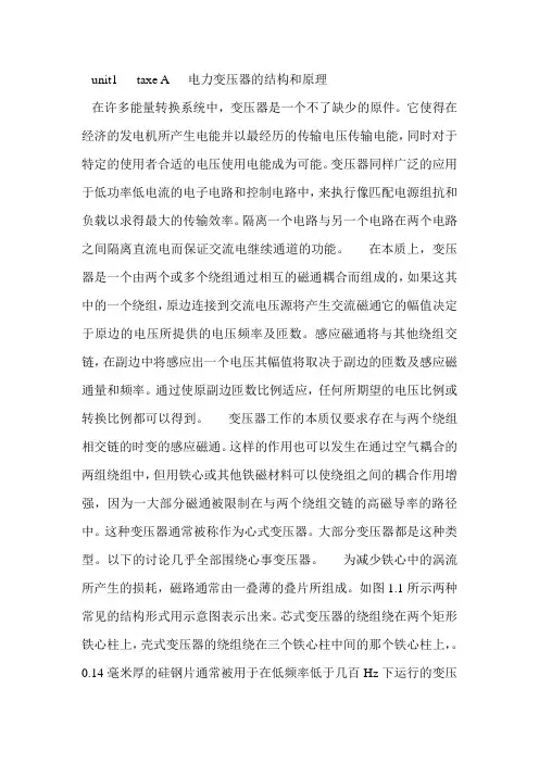
unit1 taxe A 电力变压器的结构和原理在许多能量转换系统中,变压器是一个不了缺少的原件。
它使得在经济的发电机所产生电能并以最经历的传输电压传输电能,同时对于特定的使用者合适的电压使用电能成为可能。
变压器同样广泛的应用于低功率低电流的电子电路和控制电路中,来执行像匹配电源组抗和负载以求得最大的传输效率。
隔离一个电路与另一个电路在两个电路之间隔离直流电而保证交流电继续通道的功能。
在本质上,变压器是一个由两个或多个绕组通过相互的磁通耦合而组成的,如果这其中的一个绕组,原边连接到交流电压源将产生交流磁通它的幅值决定于原边的电压所提供的电压频率及匝数。
感应磁通将与其他绕组交链,在副边中将感应出一个电压其幅值将取决于副边的匝数及感应磁通量和频率。
通过使原副边匝数比例适应,任何所期望的电压比例或转换比例都可以得到。
变压器工作的本质仅要求存在与两个绕组相交链的时变的感应磁通。
这样的作用也可以发生在通过空气耦合的两组绕组中,但用铁心或其他铁磁材料可以使绕组之间的耦合作用增强,因为一大部分磁通被限制在与两个绕组交链的高磁导率的路径中。
这种变压器通常被称作为心式变压器。
大部分变压器都是这种类型。
以下的讨论几乎全部围绕心事变压器。
为减少铁心中的涡流所产生的损耗,磁路通常由一叠薄的叠片所组成。
如图1.1所示两种常见的结构形式用示意图表示出来。
芯式变压器的绕组绕在两个矩形铁心柱上,壳式变压器的绕组绕在三个铁心柱中间的那个铁心柱上,。
0.14毫米厚的硅钢片通常被用于在低频率低于几百Hz下运行的变压器中,硅钢片具有价格低铁心损耗小,在高磁通密度下,磁导率高的理想性能,能用做高频率低能耗的标准的通讯电路中的小型变压器的铁心是由被称为铁氧体的粉末压缩制成的铁磁合金所构成的。
在这些结构中,大部分的磁通被限制在固定的铁心中与两个绕组相交链。
绕组也产生多余的磁通,像漏磁通,只经过一个绕组和另外的绕组不相交链。
虽然漏磁通只是所有磁通的一小部分,但它在决定变压器的运行情况中起着重要的作用。
毕业论文中英文翻译-变电站翻译本科毕业设计(论文)中英文对照翻译院(系部)___专业名称___________________ 年级班级_______________学生姓名___________________ 指导老师英文文献Second substation equipment over-voltage protection on electronic information system for the protection of core equipment fur the construction of a protected both pressure and other potential system, and through all levels of over-voltaj»c surge protectors of the current step by step into the land , Substation secondary safety equipment and reliable operation.1second over-voltage substation protectionJn recent years, the substation communicadon!;, communications systems, protection systems, background management module frequent over-voltage damage, the main reason for this is weak and its related systems products over-voltage protection level is or no guard against over-vol(agt 1 ^chnical measures, the consequences for the safe operation of power grids bring about a greater negative impact. With integrated automation systems and automation systems such as communication systems in the substation weak secondary by the wider use of sitch electronic systems (equipment) components of the integrated more and more, the growing volume of information storage^ speed and accuracy of the Increased and operates only a few volts, current information only microiiinp level, thus extremely sensitive to outside interference, especially the lightning and electrumagnetic pulse, such as over-voltage tolerance is low・ When thunder and lightnings such as over-voltage and accompanied by the electromagnetic fields reach a certain threshold^ ranging from system failure caused, resulted in heavy equipment or permanent damage to its components. Despite the thunder and lightning viewpoint of electronic systems (equipment) is unlikely, but lightning strike near the land, building communication and air supply line directly l^eiyun discharge form, or because of electrostatic induction nnd the impact of electromagnetic induction formation of over-voltage, There might be connected to the power lines, signal lines or grounding system, through various interfaces to transfer, coupling, radiation and other forms of invasive electronic system (equipment) und lead to serious disturbances or incidents. Therefore, strengthening and improving the electronic system (equipment) protectioru to minimize the impact of interierence by lightning and other damage caused direct losses and indirect losses, has become the urgent need to solve the prublenL2over-voltage protection design】EC (International Electrotechnical Com miss ion) TC/81 mine technical committee will be divided into internal and external mine mint in two parts, the external mine is lightning rod (or with lightning, lightning network), Vin Xiaxian and grounding system, Objects to be protected from direct lightning ^trikes^mine is to prevent internal lightning and other internal over-voltage damage caused by invasive equipment. A comprehensive mine and over-voltage protection systems must be integrated use of discharge (segregation), both pressure (and other potential), shielding (isolation), grounded, limit pressure (clamp) protection, and other technology, in accordance with the external mine And the principle of internal mine, in accordance with the targets of protective features, flexible application to take concrete measures, constitute a complete protection system. Over-voltage substation in the form are: Lightning over-voltage, the resonant frequency over-voltage and over-voltage, over-voltage operation, these over-voltage transmission or electromagnetic induction to the way the lines and equipment on a dangerous over-voltage, in particular, Lightning over-voltage, lightning substation, in the low-voltage power supply system and weak system to produce a strong over-voltage sensor, while the substation to potential rise (for example: the substation grounding resistance to 1 Q, lightning current 10 kA, while the potential for 10 kV), due to the increased potential of the counter lines and equipment damaged lines and equipment and the events have occurred, therefore, despite the substation outside the mine system (lightning rod. Yin Xiaxian And grounding devices) in line with national standards and the requirements of Buban, and the integrated automation and communications automation systems, such as weak secondary have been taken, such as shielding, grounding, isolation, filtering, and other measures, but it can not completely avoid over-voltage powerful lightning And voltage of the system counter the disruption caused damage and, therefore, the second weak system substation and a mine-voltage must also take the appropriate protective measures, in accordance with the IEC within the mine area EMP, the device's power cord, signal Lines, data lines, and the installation of lightning protection and internal over-voltage devices to prevent lightning sensors, channeling people along the lightning current, voltage counterattack, such as transient voltage surge too transient over-voltage caused by a fault and damaged electronic equipment. Over-voltage surge protection in accordance with its connection mode is divided into two series and parallel, the use of over-voltage surge protection tandem with, there may exist because of signal transmission does not match the causes of transmission of the signal interference, in particular data Communication Interface in the series were over-voltage surge protection in place, will have the normal data communications. Therefore, the data communications access I: I in the series were over-voltage surge protection in place, the transmission of data must be carried out conscientiously check if the data are not normal transmission, it maybe due to the reasons do not match the transmission signal Interference, should be replaced to match the over-voltage surge protection for. If the use of over-voltage surge protection for use of parallel, the situation is basically non-existent, but the connection mode of over-voltage surge protection for higher technical requirements.3 secondary system over-voltage substation protection 3.1points over-voltage electricity system protectionSubstation installed in the communications dispatch automation systems are used AC power or a DC power supply equipment for the rectification of its links are generally larger capacity filter capacitance, the transient over-voltage shock absorption of a certain extent, the station Low-voltage transformer side go to feed between the screen using a shielded cable and equipment have a good grounding, the use of modern technology to analyze mine, we must increase the circuit's segregation measures, because its grounding, protection and other electrical grounding all Grounding devices using the same equipment, and equipment are in a LPZOB, the relative strength of strong electromagnetic pulse, the station changed to prevent low-pressure side although there are lines intrusive wave arrester, but the residual pressure high, in the substation of lightning, through the line Coupling and the potential rise caused by over-voltage counterattack still exist, and high-pressure side of the residual pressure as high as several thousand volts, it is necessary to these scheduling automation equipmentfor the power supply over-voltage circuit protection. Lightning Protection in accordance with the principle of regional division, substation equipment in the secondary power supply system over-voltage sensors lightning protection may be two (B, C level) for the protection of segregation. B-mine use is generally greater flow capacity of the mine installations, the Lightning could be more casual Liuxie people, to achieve the objective of current limit, over-voltage at the same time will reduce to a certain extent, c-mine use With lower residual pressure of the mine installations, you can loop in the remaining scattered lightning Liuxie people, to limit the purpose of over-voltage, over-voltage equipment can be reduced to the level of tolerance. The main power supply system is inhibited lightning protection and operation of the power back to the road and over-voltage surge. According to the substation status of the substation of the second mine-sensing system and the operation and use of two over-voltage protection. As build more substations in the region more open, relatively strong electromagnetic strength, power lines and communication cables are very vulnerable to lightning attacks sensors, sensors along the over-voltage power lines and communication lines into one device, which will damage equipment, Therefore, the exchange of first-class bus to install the power protection (B level) is to ensure the safety of the entire control room, and 80 percent of the over-voltage China, scattered to the earth, play a primary role in the protection, but are still in the exchange of feeder Some of the B-level power supply voltage and mine the residual pressure increases on-line and must therefore be important in the exchange of feeder lines (DC charging screen, UPS, etc.) c-level power protection, which would curb over-voltage electrical equipment to back-end To the level of tolerance.Protective location: It is 1 EC1312 (LEMP protection "in the region of lightning protection principles. Arrester installation should be in different locations at the junction of protected areas, this network, the first-class protection should be located in the bus exchange. In Two on the bus with the installation of a B-class models of a three-phase power supply voltage surge protector.Install Location: AC bus (cabinet).For the more important feeder lines on the exchange of equipment, here for the DC charge screen, the installation of c-level three-phase power arrester. As DC charging screen is two-way exchange of electricity supply, so the screen in the DC charge with the installation of two models of c-level three-phase power supply over-voltage surge protector. Installation location should choose the DC charge screen open exchange of air power Commissioner Office.3.2integrated automation system over-voltage protectionProtective position: Computer-based integrated automation system's ability to bear a very low voltage, several hundred volts of over-voltage is enough to damage the equipment, so must the high side arrester the residual pressure (thousands of volts) to further curb to meet equipment Insulation level of need, and because of the potential rise to power and the induction loop is also over-voltage line up on KV, to be used in the exchange of integrated automation system to the exchange on the c-level single-phase installation of a surge Voltage protection. Location should choose to install automated-ping in the Composite Air switch the AC power.3.3did not ask off power supplies (UPS) over-voltage protectionProtection here: because of the internal computer systems, hubs, monitoring equipment, electric energy billing systems and so on through the UPS power supply protection, in order to protect the safety of these micro-electronics equipment, the UPS power supply device in front of the installation of a c-Surge Voltage protection. Optional models: The (UPS for single-phase power input) C-class single-phase power surge or over-voltage protection (UPS for the three-phase power input) of c-level three-phase power supply over-voltage surge protector. Installation should choose the location of UPS into the front line.3.4communication interface over-voltage protectionCommunication Interface over-voltage protection compared with the grid supply system, this over-voltage circuit on the degree of sensitivity is much higher, and these are over-voltage equipment in the circumstances itis very fragile. Equipment insulation tolerance level is very low. With the equipment connected to a signal line, data lines, measurement and control lines, and these are basically in line LPZOB region, but also through the LVZOA region, on the lines of sensors over-voltage relatively strong, according to the IEC test, when the electromagnetic field Strength increased to 0.07 GS, will have a micro-computer equipment malfunction, loss of data. And the safety of these circuits is directly related to a system of safety equipment, so important to be on the interface circuit over-voltage protection.3.4.1remote computer interface devices over-voltage protectionProtective position: As substation computer remote installations scattered distribution structure. From remote modules, intelligent telemetry module, intelligent remote control module, intelligent remote-module. The modules are installed in different automated-ping, through the RS232 interface between the modules or field bus communication. These interfaces are in the indoor circuit, equipment interface circuits shorter the distance, so there will be no more sensors to the over-voltage, but the automation equipment and other secondary equipment (measurement unit, computer, etc.) have electrical connections, when Other secondary equipment sensors to a strong over-voltage sensors, will be counter to these automation equipment, communications interface, so that damage to equipment interface circuits, it is necessary in these devices RS232 interfaces on the installation of a surge Voltage protection. Installation location should choose the remote computer interface devices, communications lines.3.4.2electric energy billing system signals over-voltage protectionA protective position: a multi-functional electronic power substationtable, energy acquisition, the electronic power meter to bear a very low voltage levels. As Meter and remote computer stations in the communications equipment used RS232 interfaces, the communication line is longer, and in LVZOB region, near the substation or by direct lightning strike at the substation, proximity to the high voltage sensors, In order to prevent damage to equipment. E-Meter in and around the RS232 port RS232installation of the over-voltage surge protector. Location should choose to install electronic power meter in and around the port, RS232.The location of protection: electronic power meter through the acquisition of information on the collector's MODEM (modem) from telephone lines to send data to a remote, since the introduction of telephone lines from the outside, thelines on the sensor to sensor lightning current relatively strong, easy to Modem interface equipment damage, it is necessary in the telephone line modem interface, the installation of an interface over-voltage surge protector. Location should choose to install telephone Chuxian inside and outside phone lines-the-line people.变电站的过电压保护是以电子信息系统为保护核心,为被保护设备构建一个均压等电位系统,并通过各级过电压浪涌保护器逐级把电流泄放入大地,使变电站设备安全和可靠地运行。
中文2795字第一部位译文部分变压器摘要:变压器是变电所的主要设备,功能是实现电网电压的等级变换,基本工作原理是电磁感应。
变配电所是实现电压等级变换和电能分配的场所。
对供电电源进行电压等级变换,应对电能进行重新分配的场所称为变电所。
建筑变电所是供配电系统的枢纽,供电电源由电网引到变电所,在变电所完成降压,电能分配等功能。
关键词:变电所;变压器;继电保护;1. 介绍要从远端发电厂送出电能,必须应用高压输电。
因为最终的负荷,在一些点高电压必须降低。
变压器能使电力系统各个部分运行在电压不同的等级。
本文我们讨论的原则和电力变压器的应用。
2. 双绕组变压器变压器的最简单形式包括两个磁通相互耦合的固定线圈。
两个线圈之所以相互耦合,是因为它们连接着共同的磁通。
在电力应用中,使用层式铁芯变压器(本文中提到的)。
变压器是高效率的,因为它没有旋转损失,因此在电压等级转换的过程中,能量损失比较少。
典型的效率范围在92到99%,上限值适用于大功率变压器。
从交流电源流入电流的一侧被称为变压器的一次侧绕组或者是原边。
它在铁圈中建立了磁通φ,它的幅值和方向都会发生周期性的变化。
磁通连接的第二个绕组被称为变压器的二次侧绕组或者是副边。
磁通是变化的;因此依据楞次定律,电磁感应在二次侧产生了电压。
变压器在原边接收电能的同时也在向副边所带的负荷输送电能。
这就是变压器的作用。
3. 变压器的工作原理当二次侧电路开路是,即使原边被施以正弦电压Vp ,也是没有能量转移的。
外加电压在一次侧绕组中产生一个小电流Iθ。
这个空载电流有两项功能:(1)在铁芯中产生电磁通,该磁通在零和±φm 之间做正弦变化,φm 是铁芯磁通的最大值;(2)它的一个分量说明了铁芯中的涡流和磁滞损耗。
这两种相关的损耗被称为铁芯损耗。
变压器空载电流Iθ一般大约只有满载电流的2%—5%。
因为在空载时,原边绕组中的铁芯相当于一个很大的电抗,空载电流的相位大约将滞后于原边电压相位90º。
附录一英文原文Generator And TransformerThe turbine turns the rotor of the electric generator in whose stator are embedded three windings. In the process mechanical power from the turbine drive is converted to three phase alternating current at voltages in the range of 11kV to 30kV line to line at a frequency of 60 Hz in the United States. The voltage is usually stepped up by transmission to remote load centers.A generator (also called an alternator or synchronous generator)is shown in longitudinal cross section; the transverse across section is approximately round. The roctoe is called round or cylindrical or smooth. We note that steam-driven turbine-generators are usually two-pole or four-pole, turning at 3600 rpm or 1800 rmp, espectively, corresponding to 60Hz.The high speeds are needed to achieve high steam turbine efficiencies. At these rotation rates, high centrifugal forces limit rotor diameters to about 3.5 ft for two pole and 7 ft for four-pole machines.The average power ratings of the turbine-generator units we have been describing have been increasing,scince1960s, fromabout 300MW to about 600MW,with maximum sizes up to about 1300MW.Inceased ratings are accompained by increased rotor and stator size, and with rotor diameters limited by centrifugal forces, the rotor lengths have been increasing. Thus in the larger sizes, the rotor lengths may be five to six times the diameters. These slender rotors resonate at critical speeds below their rated speeds and care is requied in operation to avoid sustained operation at these speeds.A Transformer is a device that changes ac electric energy at one voltage level into ac electric energy at another voltage level through the action of a magnetic field. It consists of two or more coils of wire wrapped around a common ferro magnetic core. These coils are not directly connected. The only connection between the coils is the common magnetic flux present within the core.One of the transformer windings is connected to a source of ac electric power, and the second(and perhaps third)transformer winding supplies electric power to load. The transformer winding connected to the power source is called the primary winding or input winding, and the winding connected to the power source is called the primary winding or output winding. If there is a third winding on the transformer, it is calledthe tertiary winding.Power transformer is constructed on one of two types of cores. One type of construction consists of a simple rectangular laminated piece of steel with the transformer windings wrapped around two sides of the rectangle. This type of construction is known as core form. The other type consists of a three-legged laminated core with the windings wrapped around the center leg. This type of construction is known as shell form. In either case, the core is constructed of thin laminations electrically isolated from each other in order to reduce eddy currents to a minimn.The primary and secondary windings in a physical transformer are wrapped one on top of the other with low-voltage winding innermost. Such an arrangement serves two purpose: (1)It simplifies the problem of insulating the high-voltage winding from the core. (2)It results in much less leakAge flux than would be the two windings were separated by a distance on the core.Power transformers are given a variety of different names, depending on there use in power systems. A transformer connected to the output of a generator and used to step its voltage to transmission levels is sometimes called a unit transformer. The transformer at the other end of thetransmission line, which steps the voltage down from transmission levels, is called a substation transformer. Finally, the transformer that takes his distribution levels, is called a distribution transformer. All these devices are essentially the same-the only difference among them is their intended use.In addition to the various power transformer, two-special purpose transformers are used with electric machinery and power systems. The first of these special transformers is a device specially designed to sample a high voltage and produce a low secondary voltage directly proportional to it. Such a transformer is called a potential transformer. A power transformer also produces a secondary voltage directly proportional to its primary voltage; the different between a potential transformer and a power transformer is that the potential transformer is designed to handle only a very small current. The second type of special transformer is a device designed to provide a secondary current much smaller than but directly proportional to its primary current. This device is called a current transformer.Transformers come in many sizes. Some power transformers are as big as a house. Electronic transformers, on the other hand, can be as small as a cube of sugar. All transformers have at least one coil; most have two although they may have many more.The usual purpose of transformers is to change the level of voltage. But sometimes they are used to isolate a load from the power source.Standard power transformers have two oils. These coils are labeled PRIMARY and SECONDARY. The primary coil is the one connected to the source. The secondary is the one connected to the load .There is no electrical connection between the primary and secondary. The secondary gets its voltage by induction.The only place where you will see a STEP-UP transformer is at the generating station. Typically, electricity is generated at 13,800 volts. It is stepped up to 345,000 volts for transmission. The next stop is the substation where it is stepped down to distribution levels, around 15,000 volts. Large substation transformers have cooling fins to keep them from overheating. Other transformers are located near points where the electric power is used.The coils of transformer are electrically are electrically insulated from each other. There is a magnetic link, however. The two coils are wound on the same core. Current in the primary magnetizes the core. This produces a magnetic field in the core. The core field then affects current in both primary and secondary.There are two main designs for cores:1.The CORE type has the core inside the windings.2.The SHELL type has the core outside.Smaller power transformers are usually of the core type. The very large transformers are of the shell type. There is no different in their operation, however.Coils are wound with copper wire. The resistance is kept as low as possible to keep losses low.Transformers are very efficient. The losses are often less than 3 percent. This allows us to assume that they are perfect in many computations.Perfect means that the wire has no resistance. It also means that there are no power losses in the core.Further, we assume that there is no flux leakAge. That is, all of the magnetic flux links all of the turns on each coil.To get an idea of just how small the losses are ,we can take a look at the EXCITATION CURRENT. Assume that nothing is connected to the secondary. If you apply rated voltage to the primary, a small current flows. Typically, this excitation current is less than 3 percent of rated current supplies the power lost in the core. Core losses are due to EDDY CURRENTS and HYSTERESIS.Eddy currents circulating in the core result from induction .The core is, after all, a conductor within a changing magnetic field.Hysteresis loss is caused by the energy used in lining up magnetic domains in the core. The alignment goes on continuously, first in one direction, then in the other.The other part of the excitation current magnetizes the core. It is this magnetizing current that supplies the “shuttle power”. Shuttle power is power stored in the magnetic field and returned to the source twice each cycle. Magnetizing current is quadrature with the applied voltage.Excitation current is made up of two parts. One part is in phase with the voltage.The losses that occur in real transformers have to be accounted for in any accurate model of transformer behavior.The major items to be considered in the construction shuttle such a model are.(i)Copper losses. Copper losses are the resistive heating losses in the primary and secondary windings of the transformer. They are proportional to there turn square of the current in the windings.(ii)Eddy current losses. Eddyysteresis loss is current losses are resistive heating losses in the core of the transformer.(iii)Hysteresis losses. These losses are associated with the rearrangement of the magnetic domains in the core during each half-cycle.(iv)LeakAge flux. The fluxes which escape the core and pass through only one of the transformer windings are leakAge fluxes. These escaped fluxes produce a self-inductance in the primary and secondary coils, and the effects of this inductance must be accounted for英文译文发电机和变压器汽轮机驱动发电机的转子,通过嵌在其定子槽内的三相绕组将输入的机械能转变为三相交流电能。
英文资料及其翻译TransformerTypes and Construction of TransformerA transformer is a device that alternating current electric energy at one voltage level into alternating current electric energy at another voltage level through the action of a magnetic field.It consists of two or more coils wire wrapped around a common ferromagnetic core.These coils are (usually)not directly connected. The only connection between the coils is the common magnectic flux presen within the core.One of the transformer windings is connected to a source of ac electric power,and the second(and perhaps third) transformer winding supplies electric power to loads. the transformer winding connected to the power souce is called the primary winding or input winding.and the winding connected to the loads is called the secondary winding or input winding.If there is a third winding on the transformer,it is called the tertiary winding.Power transformer are constructed on one of two types of cores.one type of construction consists of a simple rectangular laminated piece of steel with the transformer windings wrapped around two sides of the rectangle.This type of construction is know as coreform .The other type consists of three-legged laminated core with the windings wrapped around the center leg .This type of construction is know as shell form.In either case,the core is constructed of thin laminations electrically isolated form each other in order in order to reduce eddy currents to a minimum.The primary and secondary windings in a physical transformer arewrapped one on top of the other with the low-voltage winding innermost.Such an arrangement severs two purposes: 1.It simplifies the problem of insulating the high- voltage winding from the core.2.It results in much less leakage flux than would be the two windings were separated by a distance on the core.Power transformer are given a variety of different names, depending on their use in power systems.A transformer connected to the output of a generator and used to step its voltage up to transformer levels is sometimes called unit transformer. The transformer ai the other end of the transformer line,which steps the voltage down from transmission levels to distribution levels,is called a substation transformer.Finally,the transformer that takes the distribution voltage and steps is down to the final voltage ai which the power is actually used is called a distribution transformer.All these devices are essentially the same-the only difference among them is their intended use.In addition to the various power transformer, two special-purpose transformers are used with electric machinery and power systems.The first of these special transformers is a device specially designed to sample a high voltage and produce a low secondary voltage directly proportional to it.Such a transformer is called a potential transformer.A power transformer also produces a secondary voltage directly proportional to its primary voltage;the difference between a potential transformer and a power transformer is that the potential transformer is designed to handle only a very small current.The second type of special transformer is a device designed to provide a secondary current.much smaller than but directly proportional to its primary current.This device is called a currenttransformer.Cirtcuit BreakersA circuit breaker is mechanical switching device capable of making,and breaking currents under normal circuit conditions and also making.carring for a specified time ,and mediujm in which circuit interruption is performed may be designated by a suitable prefix, for example,air-blastcircuit breaker,oil circuit breaker.The circuit breakers currently in use can be dlassified into the following categories according to the arc-quenching principles:air swetches oel ciryit breakers,minmum-oil circuit breakers,air-blast circuit breakers,the magenetic air circuit breakers,minimum-oilcircuit breakers,aer-blast circuit breakers,the by voltage,insulation levelcurrent,interrupting capabilities,transient recovery coltage,interrupting tiome,and trip delay.The nameplate on a circuit breaker usually indicates:1.The maximum steady-state current it can carry, 2. The maximum interrupting current,3. The maximum line voltage,4.The interrupting time in cycles, The interrupting time in may last form 3 to 8 cycles on a 60 Hz system. To interrubt large currents quickly, we have to ensure rapid cooling. High-speed interruption lunits the damage transmission lines and equipment and, equally important,it helps to mainmain the stability of the system whenever a contingency occurs. The main parts of a circuit breaker are usually:arc-quenching chamber (or interrupter with moving and fixed contacts) operating mechanism and supporting structures.Air Switches-With increasing currents and voltages, spring-actiondriving mechanisms were developed to reduce contact buring by faster-opening ter,main contacts were fitted with arcing contacts of special material and shape,which opend after and closed before the main contacts.Further improvements of the air switch were the bursh-type contact with a wiping and cleaning function,the insulating barrier leading to arc chutes,and blowout coils with excellent arc-extinguishing properties.These features,as well as the horn gap contact,are still in use in low voltage as and de breakers.Oil Circuit Breaker Around 1900, in order to cope with the new requirement for “interrupting capacity”,AC switches were immersed in a tank of oil. Is very effective in quenching the arc and establishing the open break after current zero.Deion grids,oil-blast features,pressure-tight joints and vents,new operating mechanisims,and multiple interrupter were introucedover several decades to make the oil circuit breaker reliable apparatus for system voltage up to 362kV变压器变压器的类型和结构变压器是一个通过磁场作用将一个交流电压值变成另一个电压值的设备。
附录1 中文参考资料1.变压器是变换交流电压、电流和阻抗的器件,当初级线圈中通有交流电流时,铁芯(或磁芯)中便产生交流磁通,使次级线圈中感应出电压(或电流)。
变压器由铁芯(或磁芯)和线圈组成,线圈有两个或两个以上的绕组,其中接电源的绕组叫初级线圈,其余的绕组叫次级线圈。
2. 理想变压器不计一次、二次绕组的电阻和铁耗,其间耦合系数K=1 的变压器称之为理想变压器描述理想变压器的电动势平衡方程式为e1(t) =-N1dφ/dt、e2(t)=-N2dφ/dt若一次、二次绕组的电压、电动势的瞬时值均按正弦规律变化,则有不计铁心损失,根据能量守恒原理可得由此得出一次、二次绕组电压和电流有效值的关系令K=N1/N2,称为匝比(亦称电压比)。
3. 变压器的结构简介(1)铁心是变压器中主要的磁路部分。
通常由含硅量较高,厚度分别为0.35 mm\0.3mm\0.27 mm,表面涂有绝缘漆的热轧或冷轧硅钢片叠装而成铁心分为铁心柱和横片俩部分,铁心柱套有绕组;横片是闭合磁路之用铁心结构的基本形式有心式和壳式两种(2)绕组是变压器的电路部分,它是用双丝包绝缘扁线或漆包圆线绕成变压器的基本原理是电磁感应原理,现以单相双绕组变压器为例说明其基本工作原理:当一次侧绕组上加上电压Ú1时,流过电流Í1,在铁芯中就产生交变磁通Ø1,这些磁通称为主磁通,在它作用下,两侧绕组分别感应电势É1,É2,感应电势公式为:E=4.44fNØm 式中:E--感应电势有效值,f--频率,N--匝数,Øm--主磁通最大值,由于二次绕组与一次绕组匝数不同,感应电势E1和E2大小也不同,当略去内阻抗压降后,电压Ú1和Ú2大小也就不同。
当变压器二次侧空载时,一次侧仅流过主磁通的电流(Í0),这个电流称为激磁电流。
外文翻译TransformerA Transformer is a device that change ac electric energy at one voltage level into ac electric energy at another voltage level through the action of a magnetic filed .It consists of two or more coils of wire wrapped a common ferromagnetic core. These coils are (usually) not directly connected. The only connection between the coils is the common magnetic flux present within the core.One of the transformer windings is connected to a source of ac electric power, and the second (and perhaps third) transformer winding supplies electric power to loads. The transformer winding connected to the power source is called the primary winding or input winding, and the winding connected to the loads is called the secondary winding or output winding. If there is a third winding on the transformer, it is called the tertiary winding.Power transformers are constructed on one of two types of cores. One type of construction consists of a simple rectangular laminated piece of steel with the transformer windings wrapped around two sides of the rectangle. This type of construction is known as core form. The other type consists of a three-legged laminated core with the windings wrapped around the center leg. This type of construction is known as shell form. In either case, the1外文翻译core is constructed of thin laminations electrically isolated from each other in order to reduce eddy currents to a minimum.Power transformers are given a variety of different names, depending on their use in power systems. A transformer connected to the output of a generator and used to step its voltage up to transmission levels is sometimes called a unit transformer. The transformer at the other end of the transmission line, which steps the voltage down from transmission levels to distribution levels, is called a substation transformer. Finally, the transformer that takes the distribution voltage and steps it down to the final voltage at which the power is actually used is called a distribution transformer. All these devices are essentially the same the only difference among them is their intended use.In addition to the various power transformers, two special-purpose transformers are used with electric machinery and power systems. The first of these special transformers is a device specially designed to sample a high voltage and produce a low secondary voltage directly proportional to it, Such a transformer is called a potential transformer. A power transformer also produces a secondary voltage directly proportional to its primary voltage the difference between a potential transformer and a power transformer is that the potential transformer is designed to handle only a very small current. The second type of special transformer is a device2外文翻译designed to provide a secondary current much small than but directly proportional to its primary current. This device is called a current transformerThe ideal transformer without loss of energy, so have a 100% efficiency. In reality, the efficiency of power transformer reaches 98%, But small transformer loss will be more serious, and they may be less than 85% of efficiency. The energy loss from transformer in these phenomena: (in a coil of narrative, conductive are called "core"The current through the winding resistance, thermal conductive (current generated when the heat to higher, the human body to feel energy losses caused to). And other kinds of loss, this loss not from the core transformer.Eddy: the magnetic loss to generate electricity, iron loop back into heat energy and loss caused to the outside world. The core of don't cut into thin can reduce the loss.Magnetism loss: all are not both senders coils magnetic field lines are receiving causes energy drain.Hysteresis: core lagged effect of magnetic field changes that every cause loss of energy. This depends on the size of the loss of the core materials.Alternating magnetic field strength loss: that wire, iron and near the electromagnetic force between the metal forming and3外文翻译changing the vibration and energy drain.Magnetostrictive: the magnetic field that appear alternately core.If the core material susceptible to expansion effect of friction between the molecules, will lead to loss of energy.Cooling equipment: large transformer with cooling fan with general of water pump, or the radiator. These devices have been using energy generally count the energy loss of transformer.The overhead three phase power transmission line is the main energy corridor in a power system. One might assume that the circuit model would be trivial (ideal conductors), but three different phenomena produce effects that can not reasonably be ignored. In order of importance, they are the series voltages induced by the magnetic fields surrounding the conductors, the shunt displacement currents resulting from the electric fields between conductors,and the ohmic resistance of the conductor material. A forth,and minor, effect is the leakage conduction current that flows through contamination films on the insulators.The overhead neutrals of a typical overhead power transmission line are electrically in contact with the tower and therefore grounded, They primarily exists to provide lightning shielding for the phase conductors and also to carry zero sequence and harmonic currents that help to maintain balanced sinusoidal voltages. They are usually steel or aluminum and are small4外文翻译(diameter about lcm).The phase conductors are much larger (diameter about 5cm), and are typically stranded a1uminum surrounding a stranded steel cable (for increased tensile strength). sometimes more than one (a "bundle") comprise a phase.A11 are bare (no insulating covering) for heat dissipation reasons; the phase conductors are insulated from each other and the tower by suspension from insulator strings.5外文翻译变压器变压器是通过磁场作用将交流电从某一电压等级转换至另一个电压级别的设备。
变压器用英语怎么说变压器是利用电磁感应的原理来改变交流电压的装置,主要功能有电压变换、电流变换、阻抗变换、隔离、稳压等。
那么你知道变压器用英语怎么说吗?接下来跟着店铺来学习一下吧。
变压器的英语说法1:transformer变压器的英语说法2:voltage changer变压器相关英语表达:mains transformer;电源变压器step-down transformer;降压变压器step-up transformer;升压变压器output transformer;输出变压器input transformer输入变压器变压器的英语例句:1. He switched off the transformer and the buzzing stopped.他关掉变压器,嗡嗡声就消失了。
2. Keep away from the transformer.不要靠近那个变压器.3. We traced the trouble to a faulty transformer.我们查出故障出在一个有毛病的变压器上.4. The transformer isolates the transistors with regard to d -c bias voltage .变压器可在两个晶体管之间隔离直流偏压.5. A step - down transformer has a turns ratio less than 1.降压变压器的匝数比小于1.6. The magnetic cores of transformers and other apparatus are laminated.把变压器及其它仪器的磁心分层.7. A linear differential transformer has three coils.一个直线差动变压器有三个线圈.8. Several distributor transformers had fallen from the poles, and secondary wires and service drops were down.几个配电变压器从电线杆上摔下来, 副线及吊饰也垂下来.9. Fig. 9 shows schematically the application of a differential transformer to measurement of liquid column height.应用差动变压器测定液柱高度大致如图9所示.10. The signal is fed into a filter - amplifier which is transformercoupled to the video - detector.这个信号送到滤波器 - 放大器,它是由变压器耦合到视频检波器的.11. Advanced Transformer fastening structure, the ability to short - circuit resistance.变压器紧固结构先进, 抗短路能力强.12. HU Jing - sheng . Transformer Economic Operation. Beijing: China Power Press, 1999.胡景生. 变压器经济运行. 北京: 中国电力出版社, 1999.13. The paper also points out the direction of differential relay development.最后,本文指出了微机变压器差动保护的发展方向.14. It is very complicated to model transformer in transient calculation.在电磁暂态计算中,变压器是较难模拟的元件之一.15. Caution: the soldering iron transformer is designed for short burst operation.警告: 烙铁变压器是专为短期爆裂的运作.。
变压器专业词汇英文翻译v1.0 可编辑可修改变压器常用术语TECHNICAL TERMS COMMONLY USED FOR TRANSFORMER PART 1产品名称及类型电力变压器 Power transformer芯式变压器core type transformer 内铁式变压器core-form transformer 壳式变压器shell-form transformer 外铁式变压器shell-form transformer 密封式变压器 sealed transformer 有载调压电力变压器 power transformer with OLTC无载调压电力变压器power transformer with off-circuit tap-changer配电变压器 distribution transformer自耦变压器 auto-transformer联络变压器interconnecting transformer1.10升压变压器 step-up transformer降压变压器 step-down transformer增压变压器 booster transformer串联变压器发电机变压器 generator transformer电站用变压器 substation transformer交流变压器 converter transformer分裂变压器split-winding type transformer厂用变压器 power plant transformer所用变压器electric substation transformer单相变压器 single-phase transformer 三相变压器 three-phase transformer多相变压器 polyphase transformer单相变压器组成的三相组three-phase banks with separatesingle-phase transformer三相接地变压器 three-phase earthing transformer三线圈变压器three-winding transformer两线圈变压器 two-winding transformer 双线圈变压器double-winding transformer多线圈变压器multi-winding transformer油浸式变压器oil-immersed type transformer浸难燃油变压器noninflammable medium impregnated transformer干式变压器 dry type transformer树脂浇注式变压器 resin-casting type transformerH级绝缘变压器transformer with Hv1.0 可编辑可修改class insulation气体绝缘变压器gas insulated transformer电炉变压器 furnace transformer整流变压器 rectifier transformer列车牵引变压器 traction transformer, locomotive transformer 矿用变压器 mining transformer防爆变压器explosion-proof transformer flame-proof transformer隔离变压器 isolation transformer试验变压器 testing transformer串级式试验变压器cascade testing transformer串联变压器 series transformer增压变压器 booster transformer灯丝变压器 filament transformer电焊变压器 welding transformer钎焊变压器 brazing transformer船用变压器 marine transformer起动自耦变压器starting autotransformer起动变压器 starting transformer移动变压器 movable substation移动式 movable type成套变电站 complete substation全自动保护单相变压器complete self-protected single-phase transformer(CSP)互感器 instrument transformer测量用互感器measurement current/voltage TR保护用互感器protective current/voltage transformer电流互感器current transformer(CT)电压互感器voltage transformer potential transformer(PT)全绝缘电流互感器fully insulated current transformer母线式电流互感器bus-type current transformer绕线式电流互感器 wound primary type current transformer 瓷箱式电流互感器porcelain type current transformer套管用电流互感器 bushing-type current transformer电容式电流互感器capacitor type current transformer支持式电流互感器 support-type current transformer倒立式电流互感器 reverse type current transformer塑料浇注式电流互感器cast resinv1.0 可编辑可修改current transformer钳式电流互感器split-core type current transformer速饱和电流互感器rapid-saturable current transformer串级式电流互感器 cascade-type current transformer剩余电流互感器residual current transformer电容式电压互感器capacitor type voltage transformer接地电压互感器earthed voltage transformer不接地电压互感器unearthed voltage transformer组合式互感器combined instrument transformer剩余电压互感器residual voltage transformer移圈调压器moving-coil voltage transformer动线圈 moving winding自耦调压器 autoformer regulator接触调压器 variac感应调压器induction voltage regulator磁饱和调压器magnetic saturation voltage regulator电抗器 reactor并联电抗器 shunt reactor串联电抗器 series reactor饱和电抗器 saturable reactor铁心电抗器 iron core reactor空心电抗器 air core reactor水泥电抗器 concrete(cement) reactor三相中性点接地电抗器three-phase neutral reactor单相中性点接地电抗器single-phase neutral earthing reactor 起动电抗器 starting reactor平衡电抗器smoothing /interphase reactor调幅电抗器 modulation reactor消弧电抗器 arc-suppression reactor消弧线圈 arc-suppression coil阻波器,阻波线圈 wave trap coil镇流器 ballast密闭式 sealed type包封式 enclosed type户外式 outdoor type户内式 indoor type柱上式 pole mounting type移动式 movable type列车式 trailer mounted typev1.0 可编辑可修改自冷 natural cooling (ONAN)风冷 forced-air cooling (ONAF)强油风冷forced-oil forced-air cooling(ONAF)强油水冷forced-oil forced-water cooling (ONWF)强油导向冷却forced-directed oil cooling (OFAN)强油导向风冷却forced-directed forced-air oil cooling(ODAF) 恒磁通调压constant flux voltage variation(CFVV)变磁通调压variable flux voltage variation(VFVV)混合调压combined voltage variation(CbVV)PART2 基础词汇千瓦 kilowatt(kw)兆瓦 megawatt(MW)京瓦 gigawatt(GW)千伏 kilovolt(kV)兆伏 megavolt(MV)京电子伏 giga-electron-volt(GEV)千伏安 KVA兆伏安 MVA京伏安 GVA千乏 kilovar(kVAr)兆乏 megavar(MVAr)京乏 gigavar(GVAr)产品代号symbol of product产品型号 type of product额定电压 rated voltage额定容量 rated power额定电流 rated current连接组标号 connection symbol, symbol of connection阻抗电压 impedance voltage额定频率 rated frequency空载损耗 no-load loss涡流损耗 eddy-current loss磁滞损耗 hysteresis loss空载电流 no-load current激磁电流 exciting current负载损耗 load loss附加损耗additional losses, supplementary load loss 杂散损耗 stray losses总损耗 total losses损耗比 loss ratio冷却方式 type of cooling介质损耗 dielectric loss介损角正切值 loss tangent电压组合 voltage combination电抗电压 reactance voltagev1.0 可编辑可修改额定电压比 rated voltage ratio电阻电压 resistance voltage电压调整率 voltage regulation相位差 phase displacement相位差校验phase displacement verification零序阻抗 zero-sequence impedance短路阻抗 short-circuit impedance磁通密度 flux density电流密度 current density安匝数 number of ampere-turns轴向漏磁通 axial leakage flux径向漏磁通 radial leakage flux循环电流 circulating current热点 hot spot最热点 hottest spot局部过热 local overheat有功输出 active output满容量分接 fully-power tapping额定级电压 rated step voltage最大额定电压 maximum rated voltage最大额定电流maximum rated through-current绕组额定电压rated voltage of a winding额定短时电流rated short time current 额定短时热电流rated short thermal current额定连续热电流rated continuous current额定动稳定电流 rated dynamic current一次电流/电压primary current/voltage 二次电流/电压secondary current/voltage实际电流比actual transformation ratio of a current transformer实际电压比actual transformation ratio of a voltage transformer二次极限感应电动势secondary limiting 互感器的二次回顾路secondary circuit of CT and PT定额 rating铁心噪声 noise of core背境噪声 background noise噪声水平 noise level声级 sound level声功率级 sound power level声级试验 sound level test声级测量 sound level measurement水平加速度 horizontal acceleration垂直加速度 vertical acceleration地震 seism, earthquake地震烈度 earthquake intensity工频 power-frequencyv1.0 可编辑可修改中频 medium frequency高频 high frequency振荡频率 oscillating frequency谐振频率 resonance frequency自振频率natural frequency of vibration频率响应 frequency response谐波测量 harmonics measurement绝缘水平 insulation level绝缘强度insulation strength, dielectric strength主绝缘 main insulation纵绝缘 longitudinal insulation内绝缘 internal insulation外绝缘 external insulation绝缘配合 insulation co-ordination全绝缘 uniform insulation半绝缘 non-uniform insulation降纸绝缘 reduced insulation中心点 neutral point中心点端子 neutral terminal正常绝缘 normal insulation介电常数 dielectric constant油纸绝缘系统oil-paper insulation system绝缘电阻 insulation resistance绝缘电阻吸收比absorption ratio of insulation resistance绝缘击穿 insulation breakdown碳化 carbonization爬电距离 creepage distance沿面放电 creeping discharge放电 discharge局部放电 partial discharge局部放电测量 measurement of partial discharge超声定位ultrasonic location, ultrasonic orientation破坏性放电 disruptive discharge局部放电起始电压partial discharge inception voltage局部放电终止电压partial discharge extinction voltage过电压 overvoltage短时过电压 short time overvoltage瞬时过电压 transient overvoltage操作过电压 switching overvoltage大气过电压 atmospheric overvoltage额定耐受电压rated withstand voltage 工频耐受电压power-frequency withstand voltage感应耐压试验induced overvoltage withstand test温升试验 temperature-rise testv1.0 可编辑可修改温升 temperature rise突发短路试验 short-circuit test动热稳定 thermo-dynamic stability冲击耐压试验impulse voltage withstand test雷电冲击耐受电压lightning impulse withstand voltage操作冲击耐受电压switching impulse withstand voltage雷电冲击 lightning impulse全波雷电冲击full wave lightning impulse截波雷电冲击 chopped wave lightning impulse操作冲击 switching impulse操作冲击波switch surge, switch impulse伏秒特性voltage-time characteristics 截断时间time to chopping波前时间 time to crest视在波前时间 virtual front time半峰值时间 time to half value crest峰值 peak value, crest value有效值 root-mean-square value标么值 per unit value标称值 nominal value电级 electrode电位梯度 potential gradient等电位,等位 equipotential屏蔽 shielding静电屏蔽 electrostatic shielding磁屏蔽 magnetic shielding静电屏 electrostatic screen静电板 electrostatic plate静电环 electrostatic ring电磁感应 electro-magnetic induction电磁单元 electro-magnetic unit有效面 effective surface标准大气条件standard atmospheric condition视在电荷 apparent charge体积电阻 volume resistance导电率 admittance电导 conductance, conductivity电晕放电 corona discharge闪络 flashover避雷器 surge arrestor避雷器的残压 residual voltage of an arrestor绝缘材料耐温等级 temperature class of insulation互感器额定负荷rated burden of an instrument transformer 准确级次 accuracy classv1.0 可编辑可修改真值 true value允差 tolerance比值误差校验 ratio error verification 电流误差 current error 电压误差 voltage error互感器相角差phase displacement of instrument transformer 复合误差 composite error瞬时特性 transient characteristic瞬时误差 transient error额定仪表保安电流rated instrument security current二次极限感应电势 secondary limiting 保安因子 security factor 额定准确限值的一次电流 rated accuracy limit primary current 误差补偿 error compensation额定电压因子 rated voltage factor准确限值因子 accuracy limit factor开断电流 switched current笛卡尔坐标,直角坐标Cartesian coordinate极坐标 polar coordinate横坐标 abscissa纵坐标 ordinateX-轴 X-axis复数 complex number实数部分 real component虚数部分imaginary component正数 positive number负数 negative number小数 decimal四舍五入 round off分数 fraction分子 numerator分母 denominator假分数 improper fraction钝角 obtuse angle锐角 acute angle补角 supplementary angle余角 complement angle平行 parallel垂直 perpendicular乘方 involution开方 evolution, extraction of rootn的5次方 5th power of n幂 exponent, exponential微分,差动differential, differentiate 积分,集成integral, integrate成正比proportional to….成反比inversely proportional to…概率 probability归纳法 inductive method外推法 extrapolation methodv1.0 可编辑可修改插入法 interpolation method最大似然法maximum likelihood method 图解法graphic method有限元法 finite element method模拟法 simulation method方波回应 step response迭加电荷 superimposed charge杂散电容 stray capacitance无损探伤non-distractive flaw detection红外线扫描 infrared scanning计算机辅助设计computer aided design(CAD)计算机辅助制造computer aided manufacturing(CAM)计算机辅助试验computer aided test(CAT)近似于 approximate(approx)每分钟转数 revolution per minute(rpm)速度 velocity加速度 acceleration重力加速度 gravitational acceleration 引力 traction件数 pieces缩写 abbreviation以下简称为hereinafter referred as xxx 常用单位units commonly used包括缩写 including abbreviations分米 decimeter 厘米 centimeter海里 knot2.248 码 yard2.249 磅 pound(1b) 磅/平方英寸 pound per square inch(ppsi)英制热量单位British thermal unit (BTU)马力 horsepower压强 intensity of pressure帕斯卡 Pascal(Pa)千帕 kpa 兆帕 Mpa粘度 viscosity帕斯卡秒泊 poise 厘泊 centipoises焦耳joule(J) 千瓦时kilowatt-hour(kwh)特斯拉 tesla(T) 高斯 gaue(Gs)奥斯特 oersted(0e) 库仑 coulomb(C)微微库 Pico-coulomb(PC)达因dyne摄氏度Celsius, centigrade(℃)开尔文 Kelvin 法拉 farad(F)皮可法拉 pico-farad(pF)立方分米 cubic decimeter立方厘米 cubic centimeter桶 barrel 石油 petroleumv1.0 可编辑可修改标准国际单位制 standard international unit 厘米-克秒单位制 CGS unit环境设备 ambience apparatus校验 calibration兼容性 compatibility扩散系数 diffusion coefficient故障 fault公顷 hectarePART3 典型产品结构芯式,内铁式 core type壳式,外铁式 shell type铁心 core磁路 magnetic circuit线圈 winding, coil高压线圈 HV winding中压线圈 MV winding低压线圈 LV winding调压线圈 tapped winding, regulating winding 高压引线 high-voltage leads中压引线 mid-voltage leads低压引线 low-voltage leads夹件 clamping frame上部夹件 upper clamping下部夹件 lower clamping线圈压紧螺栓winding compressing bolt 线圈压紧装置winding compressing device线圈端部绝缘 end insulation of winding器身定位装置 positioning device for active-part定位装置 fixing device铁心垫脚 foot-plate of core垫脚 foot-pad分接引线 tapping leads, tap leads引线支架 supporting frame for leads无励磁分接开关non-excitation tap-changer无载分接开关 off-circuit tap-changer 分接选择器 tap selector 有载分接开关on-load tap-changer(OLTC) on-circuit tap-changer切换开关 diverter switch选择开关 selector switch转换选择器 change-over selector粗选择器 coarse tap selector触头组 set of contacts过度触头 transition contacts过度阻抗 transition impedance有载开关操纵机构 operating mechanism of OLTC驱动机构 driving mechanism电动机构 motor drive垂直转动轴 vertical driving shaftv1.0 可编辑可修改水平转动轴horizontal driving shaft伞尺轮盒 bevel gear box防雨罩 drip-proof cap联轴节 coupling最大分接 maximum tapping最小分接 minimum tapping额定分接rated tapping, principal tapping固定分接位置数number of inherent tapping positions工作分接位置数number of service tapping positions主分接 principal tap, main tap正分接 plus tapping负分接 minus tapping分接变换操作 tap-changer operation分接位置指示器tap position indicator 线圈分接电压tapping voltage of a winding线圈分接电流tapping current of a winding线圈分接容量tapping power of a winding分接范围 tapping range分接量 tapping quantities分接因子 tapping factor分接工作能力 tapping duty分接线 tapping step分接线 tapping connection分接引线 tapping lead小车支架及滚轮 bogie frame and wheel 箱底 tank bottom箱盖 tank cover箱沿 tank rim垫脚垫块supporting block for foot-pad 联管接头tube connector联接法兰 connecting flange加强筋,加强板 stiffener油箱垂直加强铁vertical stiffening channel of tank wall油箱活门 oil sampling valve放油活门 oil drainningvalve冷却器 cooler集中安装 concentrated installation集中安装强油循环风冷器concentrated installation of forced-oil circulating air cooler冷却器进口 inlet of cooler冷却器出口 outlet of cooler潜油泵 oil-submerged pump油流继电器 oil flow relay净油器 oil filter虹吸净油器 oil siphon filter散热器 radiatorv1.0 可编辑可修改片式散热器 panel type radiator管式散热器 tubular radiator放油塞 oil draining plug放气塞 air exhausting plug蝶阀 radiator valve butterfly valve 风扇支架supporting frame for fan motors风扇及电机 fan and motor风扇接线盒connecting box for fan motors储油柜 conservator油位计 oil-level indicator气体继电器 gas relay, buchholz realy 皮托继电器 pitot relay储油柜联管elbow joint for conservator 有载开关用储油柜conservator for OLTC 有载开关用气体继电器 gas relay for OLTC 联管 tube connector吸湿器 dehydrating breather铭牌 rating plate温度计 thermometer指示仪表柜cabinet panel for indicating instruments风扇控制柜 cabinet panel for fan motor control压力释放阀 pressure-relief valve安全气道 explosion-proof pope膨胀器 expander主排气导管 main gas-conduit分支导气管 branching gas-conduit滤油界面 tube connector for oil-filter 温度计座 thermometer socket储油柜支架supporting frame for conservator高压套管 HV bushing高压套管均压球equipotential shielding for HV bushing高压零相套管 HV neutral bushing, HV bushing phase0中压套管 MV bushing中压零相套管 MV neutral bushing, MV bushing phase0低压套管 LV bushing接地套管 earthing bushing极性 polarity极化 polarization高压套管储油柜 conservator for HV bushing相间隔板interphase insulating barrier吊攀 lifting lug安装轨道 installation rail相序标志牌 designation mark of phasev1.0 可编辑可修改sequence接地螺栓 earthing bolt视察窗 inspection hole手孔 handhole人孔 manholeMR有载开关 MR OLTCABB 有载开关 ABB OLTC伊林有载开关 ELIN OLTC3.129 F&套管 F&G bushingPART4 铁心结构多框式铁心 multi-frame type core三相三柱铁心 three-phase three-limb core三相五柱铁心three-phase five-limb core卷铁心 wound core冷轧晶粒取向硅钢片cold-rolled grain-oriented silicon sheet steel晶粒 crystalline grain高导磁硅钢片 HI-B silicon sheet steel 铁心片 core lamination 一迭铁心 a lamination stock铁心迭积图lamination drawing, lamination diagram迭片 lamination迭片系数 lamination factor空间利用系数 space factor层间绝缘 layer insulation斜接缝 mitring45°斜接缝45°mitred joint斜接缝的交错排列方式over-lay arrangement for mitred joints of lamination重迭 overlap铁心油通 oil-duct of core铁心气道air ventilating duct of core 阶梯接缝stepped lay joint对接铁心 butt jointed core渐开线铁心 evolute core, involute core 空气隙 air gap铁心拉板 tensile plate of core limb, core drawplate铁心柱 core limb, core lge轭,铁轭 yoke上轭 upper yoke下轭 lower yoke旁轭 side yoke, return yoke环氧绑扎带 epoxy-bonded bandage轭拉带 yoke tensile belt铁轭拉带 banded band of core yoke上轭顶梁 top jointing beam of upper yoke侧梁 side beam夹件 clamping framev1.0 可编辑可修改铁心夹件 core clamps, coreframe铁轭夹件 yoke clamping, yoke clamps上夹件 upper yoke clamping, upper yoke clamps下夹件lower yoke clampings, lower yoke clamps夹件腹板 web of yoke clamping夹件肢板 limb of yoke clamping夹件加强stiffening plate of clamping 压线圈的压钉winding compressing bolt 压钉螺母 nut for compressing bolt弹簧压钉 compressing bolt with spring 油缸压钉compressing bolt with hydraulic damper线圈支撑架 winding supporter线圈支撑架 winding supporting plate垫脚 foot pad定位孔 positioning hole带螺母的定位柱 positioning stud拉螺杆 tensile rod夹件夹紧螺杆 yoke clamping bolt铁心接地片 core earthing strip铁心地屏 earthing screen of code旁轭地屏earthing screen of side yoke 接地屏蔽earthing shield铁心窗高 core window height中心距M center line distance M铁心中间距center distance between lombs木垫块 wood padding block迭片系数 lamination factor铁心的级 stage of lamination stacks心柱外接圆circumscribed circle of core leg铁心端面 core surface perpendicular to lamination木棒 wood bar, wood rod定位板 positioning platePART5 线圈结构圆筒式线圈 cylindrical winding层式线圈 layer winding饼式线圈 disk winding单层圆筒式线圈single layer cylindrical winding双层圆筒式线圈double layer cylindrical winding多层圆筒式线圈multi-layer cylindrical winding大型层式线圈large size long layer winding分段圆筒式线圈sectional layer winding分段多层圆筒线圈sectional multi-layer windingv1.0 可编辑可修改连续式线圈 continuous winding半连续式线圈semi-continuous winding 纠结式线圈interleaved winding纠结饼式线圈interleaved disc winding 纠结—连续式线圈interleaved-continuous winding部分纠结式线圈partial-interleaved winding插花纠结式线圈 sandwich-interleaved winding内屏连续式线圈innershield-continuous winding插入电容式线圈capacitor shield winding高串联电容线圈high series capacitance winding双饼式线圈 twin-disk winding交错式线圈sandwich winding, staggered winding螺旋式线圈helical winding, helix winding半螺旋式线圈 semi-helical winding单列螺旋式线圈single-row helical winding双列螺旋式线圈double-row helical winding三列螺旋式线圈three-row helical winding短螺旋式线圈 short helical winding螺旋式线圈引出端的固定terminal fixing for helical winding分裂式线圈 split winding分段式线圈 sectional winding箔式线圈 foil winding全绝缘线圈uniformly insulated winding分级绝缘线圈gradedly insulated winding, winding with non-uniform insulation第三线圈 tertiary winding高压线圈 high-voltage winding中压线圈mid-voltage winding, intermediate voltage winding 低压线圈 low-voltage winding调压线圈 regulating winding, tapped winding辅助线圈 auxiliary winding平衡线圈 balance winding稳定线圈 stabilizing winding公共线圈 common winding串联线圈 series winding连耦线圈 coupling winding励磁线圈 exciting winding, energizing windingv1.0 可编辑可修改一次线圈 primary winding二次线圈 secondary winding左绕 left-wound右绕 right-wound星形联结 star connection三角形联结 delta connection曲折形联结 zigzag connectionT形联结 scott connection开口三角形联结open-delta connection 开口线圈open winding线段 winding disk, winding section线层 winding layer匝绝缘 turn insulation层绝缘 layer insulation段绝缘insulation between disks, section insulation端绝缘 end insulation顶部端环 top support ring分接头 tapping terminal分接区 tapping zone段间横垫块 radial spacer between disks 燕尾垫块 chock燕尾撑条 dovetail strip垫块的厚度 spacer thickness垫块的宽度 spacer width撑条 stick, duct strip轴向撑条 axial strip油道 oil-duct, oil passage径向油道 radial oil-duct段间油道 oil-duct between disks段间过度联线transfer connection between disks段间换位联线transposed connection between disksS弯 S-bend线圈起始端 initial terminal of winding 线圈终端 final terminal of winding轴向深度 axial depth径向深度 radial depth绝缘纸筒 insulating cylinder匝间绝缘 turn insulation绝缘角环insulating angled ring (collar ring)线匝间垫条insulating filling strips between turns分数匝fractional turn整数匝 integer turn近似一圈 approximate roll并绕导线 parallel wound conductors多股导线 multi-strand conductors电磁线 electro-magnetic conductor组合导线 composite conductor换位导线transposed conductor, transposed cablev1.0 可编辑可修改纸包线 paper wrapped conductor纸包导线 covered conductor漆包线 enameled conductor圆线 round wire硬拉铜导线 hard drawn copper conductor 退火导线 annealed conductor玻璃丝包线glass-fiber covered conductor纸槽 paper channel绑线 binding wire绑绳 binding rope静电板 electrostatic plate静电环 electrostatic ring端部电容环capacitive layer end ring 端部电容屏capacitive layer end screen 屏蔽环 shielding ring屏蔽线 shielding conductor屏蔽角环 shroud petal绝缘包扎 insulation wrapping线圈总高度 overall height of winding 铜线高度 copper height of winding线圈调整 trimming of winding线圈浸漆varnish impregnation of winding线圈的换位 transposition of winding标准换位 standard transposition分组换位 transposition by groups线圈展开图planiform drawing of winding线圈的干燥与压缩drying and compressing of winding绝缘的压缩收缩率shrinkage of insulation under compression 无氧铜导线deoxygenized copper conductor铝合金导线 aluminum-alloy conductor PART6 油箱结构及附件钟罩式油箱 bell type tank上节油箱 upper part of tank下节油箱 bottom part of tank箱壁 tank wall带磁屏箱壁tank wall with magnetic shield箱底 tank bottom箱盖 tank cover箱沿 tank rim箱沿护框 pad frame for tank rim gasket 边缘垫片 rim 加强筋,加强板 stiffener联管头 tube connecting flange放油活门 draining valve油样活门 oil sampling valve油样活塞 oil sampling plug闸阀 gate valvev1.0 可编辑可修改蝶阀 butterfly valve球阀 ball valve压力释放阀 pressure relief valve安全气道 explosion-proof pipe真空接头connecting flange for evacuation滤油接头connecting flange for oil filter水银温度计pocket for mercury thermometer铭牌底板 base plate of rating plate手孔 handhole人孔 manhole6.27 升高座ascending flanged base turret吊攀 lifting lug千斤顶支座 jacking lug定位钉 positioning pin盖板 cover plate临时盖板 temporary cover plate带隔膜储油柜 conservator with rubber diaphragm 带胶囊储油柜 conservator with rubber bladder沉淀盒 precipitation well导气管 air exhausting pipe导油管 oil conduit吊环 lifting eyebolt有围栏的梯子 ladder with balustrade适形油箱 form-fit tank呼吸器 breather气体继电器 gas relay, buchholz relay 皮托继电器 pitot relay 流动继电器 flow relay风冷却器air cooler水冷却器 water cooler冷却器托架 bracket for cooler冷却器拉杆 tensile rod for cooler潜油泵 oil-submerged pump流量 flow quantity扬程 lift控制箱 control box控制盘 control panel端子箱 terminal box端子排 terminal block风扇接线盒connecting box for fan-motors金属软管 metallic hose封闭母线联结法兰joint flange for enclosed bus-bar管式油位指示器tubular oil-level indicator磁铁式油位指示器magnetic type oil-level indicatorv1.0 可编辑可修改PART7 铁心制造产品制造 manufacturing of products硅钢片纵剪silicon steel sheet slitting硅钢片横剪 silicon steel sheet cutting to length多刀滚剪机 multi-disk-cutter slitting machine纵剪 slitting横剪 cut-to-length纵剪生产线 slitting line横剪生产线 cut-to-length line开卷机 decoiler毛刺 burr铁心片预迭pre-stacking of core lamination铁心迭装 core assembly铁心迭片 core lamination选片 pre-selection of lamination迭片 lamination stacking两片一迭 stacked by two-sheet打(敲)齐 knock to even迭装流转台core assembly tilting platform不迭上轭 core stacking without upper yoke打铁心用垫块 knock block铁心料盘 lamination stocking tray卷铁心机 core winding machine铁心退火 core annealing铁心中间试验 interprocess core test片的角度偏差 angular misalignment of lamination宽度偏差 width deviation长度偏差 length deviation铁心的垂直度 verticality of core铁心起立 tilt the core into vertical position迭片的定位挡板positioning stopper for core assembly硅钢片的涂漆varnish coating of silicon steel sheet片间绝缘试验lamination insulation test半导体粘带 semi-conductive adhesive tape半干环氧粘带semi-cured epoxy adhesive tape粘带的固化 cure of adhesive tape夹紧铁心工具clamping tools for core 铁心柱的夹紧装置tightening device for core leg铁心翻转台 tilting platform of core 螺旋千斤顶 screw jack。
毕业设计英文文献翻译(电力方向附带中文)大学毕业设计英文文献翻译,关于电力系统方向,电力谐波!绝对原创!HarmonicsService reliability and quality of power have become growing concerns for many facility managers, especially with the increasing sensitivity of electronic equipment and automated controls. There are several types of voltage fluctuations that can cause problems, including surges and spikes, sags, harmonic distortion, and momentary disruptions. Harmonics can cause sensitive equipment to malfunction and other problems, including overheating of transformers and wiring, nuisance breaker trips, and reduced power factor.What Are Harmonics?Harmonics are voltage and current frequencies riding on top of the normal sinusoidal voltage and current waveforms. Usually these harmonic frequencies are in multiples of the fundamental frequency, which is 60 hertz (Hz) in the US and Canada. The mostcommon source of harmonic distortion is electronic equipment using switch-mode power supplies, such as computers, adjustable-speed drives, and high-efficiency electronic light ballasts.Harmonics are created by these Dswitching loads‖ (also called “nonlinear loads,‖ because current does not vary smoothly with voltage as it does with simple resistive and reactive loads): Each time the current is switched on and off, a current pulse is created. The resulting pulsed waveform is made up of a spectrum of harmonic frequencies, including the 60 Hz fundamental and multiples of it. This voltage distortion typically results from distortion in the current reacting with system impedance. (Impedance is a measure of the total opposi tion―resistance, capacitance, and inductance―to the flow of an alternating current.) The higher-frequency waveforms, collectively referred to as total harmonic distortion (THD), perform no useful work and can be asignificant nuisance.Harmonic waveforms are characterized by their amplitude and harmonic number. In the U.S. and Canada, the third harmonic is 180 Hz―or 3 x 60 Hz―and the fifth harmonic is 300 Hz (5 x 60Hz). The third harmonic (and multiples of it) is the largest problem in circuits with single-phase loads such as computers and fax machines. Figure 1 shows how the 60-Hz alternating current (AC) voltage waveform changes when harmonics are added.大学毕业设计英文文献翻译,关于电力系统方向,电力谐波!绝对原创!The Problem with HarmonicsAny distribution circuit serving modern electronic devices will contain some degree of harmonic frequencies. The harmonics do not always cause problems, but the greater the power drawn by these modern devices or other nonlinear loads, the greater the level of voltage distortion. Potential problems (or symptoms of problems) attributed to harmonics include:■ Malfunction of sensitive equipment■ Random tripping of circuit breakers■ Flickering lights■ Very high neutral currents■ Overheated phase conductors, panels, and transformers ■ Premature failure of transformers and uninterruptible power supplies (UPSs)■ Reduced power factor■ Reduced system capacity (because harmonics create additional heat, transformers and otherdistribution equipment cannot carry full rated load)Identifying the ProblemWithout obvious symptoms such as nuisance breaker trips or overheated transformers, how do you determine whether harmonic current or voltages are a cause for concern? Here are several suggestions for simple, inexpensive measurements that a facility manager or staff electrician could take, starting at the outlet and moving upstream:■ Measure the peak and root mean square (RMS) voltage at a sample of receptacles. The Dcrest factor‖ is the ra tio of peak to RMS voltage. For a perfectly sinusoidal voltage, the crest factor will be 1.4. Low crest factor is a clear indicator of the presence of harmonics. Note that these measurements must be performed with a Dtrue RMS‖ meter―one that doesn‘t assume a perfectly sinusoidal waveform.■ Inspect distribution panels. Remove panel covers and visually inspect components for signs of overheating, including discolored or receded insulation or discoloration of terminal screws. If you see any of these symptoms, check that connectionsare tight (since loose connections could also cause overheating), and compare currents in all conductors to their ratings.■ Measure phase and neutral currents at the transformer secondary with clamp-on current probes. If no harmonics are being generated, the neutral current of a three-phase distribution system carries only the imbalance of the phase currents. In a well-balanced three-phase distribution system, phase currents will be very similar, and current in the neutral conductor should be much lower than phase current and far below its rated current capacity. If phase currents are similar and neutral current exceeds their imbalance by a wide margin, harmonics are present. If neutral current is above 70 percent of the cond uctor‘s rated capacity, you need to mitigate the problem.■Compare transformer temperature and loading with nameplate temperature rise and capacity ratings. Even lightly loaded transformers can overheat if harmonic current is high. A transformer that is near or over its rated temperature rise but is loaded well below its rated capacity is a clear sign that harmonics are at work. (Many transformers have built-in temperature gauges. If yours does not, infrared thermography can be used to detect overheating.)大学毕业设计英文文献翻译,关于电力系统方向,电力谐波!绝对原创!In addition to these simple measurements, many power-monitoring devices are now commercially available from a variety of manufacturers to measure and record harmonic levels. These instruments provide detailed information on THD, as well as on the intensity of individual harmonic frequencies. After taking the appropriate measurements to determine whether you have high levels of harmonics and, if so, to find the source, you will be well-positioned to choose the best solution.Solutions to Harmonics ProblemsThe best way to deal with harmonics problems is through prevention: choosing equipment and installation practices that minimize the level of harmonics in any one circuit or portion of a facility. Many power quality problems, including those resulting from harmonics, occur when new equipment is haphazardly added to older systems. However, even within existing facilities, the problems can often be solved with simple solutions such as fixing poor or nonexistent grounding on individual equipment or the facility as a whole, moving a few loads between branch circuits, or adding additional circuits to help isolate the sensitiveequipment from what is causing the harmonic distortion. If the problems cannot be solved by these simple measures, there are two basic choices: to reinforce the distribution system to withstand the harmonics or to install devices to attenuate or remove the harmonics. Reinforcing the distribution system means installing double-size neutral wires or installing separate neutral wires for each phase, and/or installing oversized or Krated transformers, which allow for more heat dissipation. There are also harmonic-rated circuit breakers and panels, which are designed to prevent overheating due to harmonics. This option is generally more suited to new facilities, because the costs of retrofitting an existing facility in this way could be significant. Strategies for attenuating harmonics, from cheap to more expensive, include passive harmonic filters, isolation transformers, harmonic mitigating transformers (HMTs), the Harmonic Suppression System (HSS) from Harmonics Ltd., and active filters(Table 1).Passive filters (also called traps) include devices that provide low-impedance paths to divert harmonics to ground and devices that create a higher-impedance path to discourage the flow of harmonics. Both of these devices, by necessity, change theimpedance characteristics of the circuits into which they are inserted. Another weakness of passive harmonic technologies is that, as their name implies, they cannot adapt to changes in the electrical systems in which they operate. This means that changes to the electrical system (for example, the addition or removal of power factorCcorrection capacitors or the addition of more nonlinear loads) could cause them to be overloaded or to create Dresonances‖ that could actually amplify, rather than diminish, harmonics.Active harmonic filters, in contrast, continuously adjust their behavior in response to the harmonic current content of the monitored circuit, and they will not cause resonance. Like an automatic transmission in a car, active filters are designed to accommodate a full range of expected operating conditions upon installation, without requiring further adjustments by the operator.Isolation transformers are filtering devices that segregate harmonics in the circuit in which they are created, protecting upstream equipment from the effects of harmonics. These transformers do not remove the problem in the circuit generating the harmonics, but they can prevent the harmonics from affecting more sensitive equipment elsewhere within the facility.大学毕业设计英文文献翻译,关于电力系统方向,电力谐波!绝对原创!Harmonic mitigating transformers actually do relieve problematic harmonics. HMTs can be quite cost-effective in the right application, because they can both improve reliability and reduce energy costs. The right application includes transformers that are heavily or moderately loaded and where high levels of harmonic currents are present. In addition, HMTs are very effective in supporting critical loads that are backed up by a UPS. UPSs and backup generators tend to have high impedance, which results in high voltage distortion under nonlinear loading. Because of this, equipment that operates flawlessly when supplied by utility power may malfunction when the backup system engages during a utility outage. Note that some of these power systems have output filters (either passive or active) to control harmonic levels. The presence or absence of such filters should be determined before adding an HMT.The Harmonics Ltd. Harmonic Suppression System is a unique solution for single-phase loads that is designed to suppress the third harmonic. An HSS is generally more expensive than an HMT, but it is designed to attenuate the harmonicsproblems throughout the entire distribution system, not just upstream of the transformer. The types of facilities that present the best opportunities for HSS installation are those that place a very high premium on power quality and reliability, such as server farms, radio and television broadcast studios, and hospitals. (See .) Economic EvaluationEvaluating the life-cycle costs and effectiveness of harmonics mitigation technologies can be ve ry challenging―beyond the expertise of most industrial facility managers. After performing the proper measurement and analysis of the harmonics problem, this type of evaluation requires an analysis of the costs of the harmonics problem (downtime of sensitive equipment, reduced power factor, energy losses or potential energy savings) and the costs of the solutions. A good place to start in performing this type of analysis is to ask your local utility or electricity provider for assistance. Many utilities offer their own power quality mitigation services or can refer you to outside power quality service providers.Additional ResourcesInstitute of Electrical and Electronics Engineers (IEEE),Standard 519-1992, DIEEE大学毕业设计英文文献翻译,关于电力系统方向,电力谐波!绝对原创!Recommended Practices and Requirements for Harmonic Control in Electric Power Systems‖ (1992), available at .Relationship between harmonics and symmetrical componentsAbstract New terminology is introduced to make clear the relationship between harmonics and symmetrical components. Three-phase sets are classified in terms of symmetrical sets and asymmetrical sets. Subclasses are introduced with the names symmetrical balanced sets, symmetrical unbalanced sets, asymmetrical balanced sets and asymmetrical unbalanced sets to show that a threephase set can resolve to either one, two or three symmetrical component sets. The results from four case studies show that these subclasses and their resolution to symmetrical component sets improve understanding of harmonic analysis of systems having balanced and unbalanced harmonic sources and loads.Keywords asymmetrical sets; harmonic flows; harmonic sources; symmetrical component sets; symmetrical sets Any periodic wave shape can be broken down into oranalysed as a fundamentalwave and a series of harmonics.Three-phase harmonic analysis requires a clear understanding of the relationship between symmetrical component injections from harmonic sources (e.g. adjustable speed drives, ASDs) and their relationship to harmonic flows (symmetrical components) arising from the application of a harmonic source to a linear system.Alimited number of references contain brief information concerning harmonics and symmetrical components. Reference 1, provides a paragraph on this topic and uses the heading Relationship between Harmonics and Symmetrical Components‘.It includes a table that is supported by a brief explanatory paragraph. The table expresses harmonics in terms of positive, negative and zero sequences. It states that these sequences are for harmonics in balanced three-phase systems. The heading refers to symmetrical components while the content refers to balanced three-phase systems. Herein lies the anomaly. Classically, symmetrical components (especially ero sequence) are only applied in unbalanced systems. The following questions rose after reading the Ref. 1 paragraph.(a)Do symmetrical components (especially zero sequence), in the classical sense,apply in balanced as well as unbalanced non-sinusoidal systems and is this abreak from tradition?(b)What do the terms, symmetrical, asymmetrical, balanced, unbalanced andsymmetrical components mean?(c)What are the conditions under which a system must operate so that harmonicsresolve to positive, negative and zero sequences and is the table given inRef. 1 correct?The terminology used is found inadequate for describing non-sinusoidal systems.There is thus a need to introduce a three-phase terminology that will show the relationship and make the comparison between injections (currents) and harmonic flows (voltages and currents) meaningful.References 3 provides the basis for the solution by providing definitions for threephase sets‘, symmetrical sets‘an d symmetricalcomponent sets‘.The purpose of this paper is to introduce an approach to harmonic analysis大学毕业设计英文文献翻译,关于电力系统方向,电力谐波!绝对原创!based on the classification of three-phase sets and to make to comparison between injections from harmonic sources and corresponding harmonic flows quantifiable by expressing the results in terms of the number of symmetrical component sets found.Harmonic flows and their resolution to symmetrical components depends upon the magnitudes and phase sequences of the injections from a harmonic source, on the system‘s sequence impedances, on three- and four-wire connections and on whether the customer‘s linear load on the system is balanced or unbalanced. Therefore, what is injected in terms of symmetrical component sets by a harmonic source is not necessarily received by the system, i.e. the harmonic flows may resolve to one, two or three symmetrical component sets and this depends upon the type of three-phase set found. Therefore, any three-phase harmonic may be partially made up of any of thesymmetrical component sets.Four case studies are reported and they show a novel method for teaching the flow of power system harmonics. It is important to use case studies as part of one‘s teaching as they link learning to concepts and improve understanding. They show how the method of symmetrical components can be extended to a system‘s response to harmonic flows. When taught as a group, the four case studies improve cognitive skills by showing that the symmetrical component responses under unbalanced situations are different to the balanced state.IEEE __TIONS ON POWER __NICS VOL.19,NO.3,__年大学毕业设计英文文献翻译,关于电力系统方向,电力谐波!绝对原创!谐波服务的可靠性和电能质量已成为越来越多设施经理的关注,尤其是随着电子设备和自动化控制灵敏度提高了很多。
附录附录A 外文资料Design of Mv/Lv Substation TransformerAbstract:A substation is a part of an electrical generation, transmission, and distribution system. Substations generally have switching, protection and control equipment, and transformers. The low voltage distribution networks are supplied from MV/LV substation transformer that represent the last step of bringing transformation to the low voltage and ensuring the protection and monitoring of the network. There are three types of MV/LV substation: pole-mounted transformer substation, the substation in an envelope and substation in masonry. This paper presents a general description for different MV/LV substation and a methodology to design the various elements making up the public distribution substation (choice of the emplacement, engineering, power transformer, choice of MV cells, circuit breakers, fuses, disconnect switch, conductors,...etc).Keywords:Substation transformer MV cells Substation in masonryPole-mounted transformer substation1. IntroductionA substation is a part of an electrical generation, trans-mission, and distribution system. Substations transform voltage from high to low, or the reverse, or perform any of several other important functions. Electric power may flow through several substations between generating plant and consumer, and its voltage may change in several steps. Substations generally have switching, protection and control equipment, and transformers. Distribution circuits are fed from a transformer located in an electrical substation, where the voltage is reduced from the high values used for power transmission.Distribution networks are typically of two types, radial or interconnected. A radial network leaves the station and passes throughthe network area with no normal connection to any other supply. This is typical of long rural lines with isolated load areas. An interconnected network is generally found in more urban areas and will have multiple connections to other points of supply. These points of connection are normally open but allow various con-figurations by the operating utility by closing and opening switches. Operation of these switches may be by re-mote control from a control center or by a lineman. The benefit of the interconnected model is that in the event of a fault or required maintenance a small area of network can be isolated and the remainder kept on supply.The MV/LV substations are a node of a network, which includes a set of equipment designed to protect and facilitate the operation of the electrical energy . The MV/LV substations provide the interface between the distribution MV and LV. The MV / LV adapts to all modes of operation and why should fulfill the following functions:● Distribute the power and protect the LV departures;● Isolate the MV/LV substation in case of default;●Manage the MV network in case of default and the position by remote control.MV/LV substation transformer has two purposes:- The interconnection between the lines of the same voltage level, it helps to distribute the power of the different lines from substations.- The transformation of electrical power, processors can switch between voltage levels to another.So, we can classify the MV/LV substations over the networks on which they are used as well as the functions they perform. The realization of MV/LV substations needs prior knowledge:●Standards of reference and statutory instruments (voltage, quality of supply, short-circuit power, ..., etc);● Needs to be performing (power plant availability, operation);●Specific needs-related uses (voltage variations tolerated, compensation of reactive power, immunity to interference receivers, regulations related to facility security);● Constraints, installation and environment .This paper presents the different MV/LV substation transformer and a methodology to design the various elements making up the public distribution substation. 2. The Birth of MV/LV Substation TransformerThe decision of a MV or LV supply will depend on local circumstances and considerations such as those mentioned above, and will generally be imposed by the utility for the district concerned. When a decision to supply power at MV has been made, there are two widely-followed methods of proceeding:● The power-supplier constructs a standard substation close to the consumer’s premises, but the MV/LV transformer is located in transformer chamber inside the premises, close to the load centre.● The consumer constructs and equips his own substation on his own premises, to which the power supplier makes the MV connection .2.1. Project StudiesThe consumer must provide certain data to the utility at the earliest stage of the project. the power-supplier must indicate:●The type of power supply proposed, and define the kind of power-supply system: over headline or under-ground-cable network, the service connection details: single-line service, ring-main installation, or parallel feeders, and the power (kVA) limit and fault current.●The nominal voltage and rated voltage (Highest volt- age for equipment)●Metering details which define: The cost of connection to the power network and tariff details (consumption and standing charges).2.2. ImplementationBefore any installation work is started, the official agreement of the power-supplier must be obtained. The request for approval must include the following information, largely based on the preliminary exchanges noted above:● Location of the proposed substation;● Single-line diagram of power circuits and connections, together with earthing-circuit proposals;● Full details of electrical equipment to be installed, including performance characteristics;● Layout of equipment and provision for metering components;● Arrangements for power-factor improvement if required;●Arrangements provided for emergency standby power plant (MV or LV) if eventually required.●Prefabricated substations.3. Classification of Mv/Lv Substation Transformer BirthSubstations transformer may be classified according to metering arrangements(Mv or Lv) and type of supply(overhead line or underground cable),Substations transformer are classified into three types:●Substation in masonry: Installed in a dedicated enclosure prefabricated or not, with indoor equipment (switchgear and transformer) ;●Pole mounted(S ≤160kVA)with dedicated outdoor equipment (switchgear and transformer);● Prefabricated substations.3.1. Pole Mounted SubstationsThese substations are mainly used to supply isolated rural consumers from MV overhead line distribution systems. In this type of substation, most often, the MV transformer protection is provided by fuses.The kinds of outdoor substation are common in some countries, based on weatherproof equipment exposed to the elements. The pole mounted substation is the easiest, it is used in cases where the power transformer is less than or equal to 160 KVA.3.2. Prefabricated SubstationsPrefabricated substations provide a particularly simple, rapid and competitive choice. The MV/ LV prefabricated are made using: MV cells, transformer …etc, grouped in an envelope whose role is the protection of internal equipment against external influences and to ensure a degree of protection against the public. The prefabricated substations are manufactured, wired and tested at the manufacturer, bringing the transformer, the LV and MV switchgear, connections and auxiliary equipment limit the study time and achievement. The transformer and switchgear are assembled in a metal case, the start is done by airline or underground, these substations are very compact and their implementation is very fast, one of the best-known benefits:● Simplified civil engineering (platform only);● Immediate availability;● Limited space and time.●The prefabricated substation is transported by truck. It is placed on a concrete slab.3.3. Masonry SubstationOperating a distribution network sometimes requires switching points in addition to the HV/MV substations, in order to limit the effect of a fault on the network. Distribution substations in masonry may be classified into three types:● Public Distribution substations (DP);● Distribution substations with LV metering (S ≤ 630 kVA);●Distribution substations with MV metering called specific substations (a transformer whose power S> 630 kVA or several transformers).4. Design of Public Distrubution SubstationPublic distribution substations with prefabricated cells metal is done with cells each fulfilling a function. The public distribution substation includes:● 02 incoming panels,● Fuse-switch combination or fused switch;● Fault detector for MV underground;● LV circuit breaker (Table of public distribution);● Power Transformer 100,160, 250, 400.630 KVA;● Cell power transformer (closing metal);● Safety equipment;● Boxes of deflector;● Boxes end external and internal;● MV cable and lugs;● Spare fuses;5. ConclusionIn this paper, we presented a synthesis of the various MV/LV substation transformer, we have explained below the various documents constituting technical study, a detailed study of the public distributionsubstations Operating a distribution network requires switching points in addition to the MV/LV substations, in order to limit the effect of a fault on the network. To build a MV/LV substation transformer, it is necessary to size a number of parameters to achieve the appropriate wiring diagram. The development of these components must meet certain conditions dictated by the dual concern for the safety of operation and lower operating costs. These construction conditions can be classified into conditions related to tension, conditions relating to the thermal effects of the current, and conditions relating to the safety of operating personnel.From: 2013.51b004 Published Online January 2013(/journal/eng)中压/低压变电站变压器的设计摘要:变电站是电力系统中的发电、输电、和配电的一部分。
Types and Construction of TransformerA Transformer is a device that changes ac electric energy at one voltage level into ac e1ectric energy at another vo1tage level through the action of a ma8netic field.It consists of two or more coil of wire wrapped around a common ferromagnetic core.These coils are (usually) not directly connected.The only connection between the coils is the common magnetic flux present within the core.One of the transformer windings is connected to a source of ac electric power,and the second (and perhaps third) transformer winding supplies electric power to loads.The transformer winding connected to the power source is called the primary winding or input winding,and the winding connected to the loads is called the secondary winding or output winding. If there is a third winding on the transformer,it is called the tertiary winding.Power transformer are constructed on one of two types of cores.One type of construction consists of a simple rectagu1arlaminated piece of steel with the transformer windings wrapped around two sides of the rectangle. This type of construction is known as core form.The other type consists of a three-legged laminated core with the windings wrapped around the center leg.This type of construction is known as shell form. In either case,the core is constructed of thin laminations electrically isolated from each other in order to reduce eddy currents to a minimum.The primary and secondary windings in a physical transformer are wrapped one on top of the other with the low-voltage winding innermost.Such an arrangement serves two purposes:1.It simplifies the problem of insulating the high-voltage winding from the core.2.It results in much less leakage flux than would be the two windings were separated by a distance on the core.Power transformers are given a variety of different names, depending on their use in power systems. A transformer connected to the output of a generator and used to step its vo1tage up to transmission levels is sometimes called a unit transformer.The transformer at the other end of the transmission line,which steps the voltage downfrom transmission levels to distribution levels is called a substation transformer. Finally,the transformer that takes the distribution voltage and steps it down to the final vo1tage at which the power is actually used is called a distribution transformer.A11 these devices are essentially the same the only difference among them is their intended use.In addition to the various power transformers,two special-purpose transformers are used with electric machinery and power systems.The first of these special transformers is a device specially designed to sample a high vo1tage and produce a low secondary vo1tage directly proportional to it. Such a transformer is called a potential transformer.A power transformer also produces a secondary vo1tage directly proportional to its primary voltage; the difference between a potential transformer and a power transformer is that the potential transformer is designed to handle only a very small current. The second type of special transformer is a device designed to provide a secondary current much smaller than but directly proportional to its primary current.This device is called a current transformer.The Directional Protection BasisEarly attempts to improve power-service reliability to loads remote from generation led to the dual-1ine concept.Of course,it is possible to build two 1ines to a load,and switch the load to whichever line remains energized after a di51urbance.But better service continuity will be available if both lines normally feed the load and only the faulted line is tripped when disturbances occur.Fig.1-l shows a sing1e-generator,two-1ine,single-load system with breakers properly arranged to supply the load when one line is faulted.For the arrangement to be effective it is necessary to have the proper relay application.Otherwise,the expensive power equipment will not be able to perform as p1anned.Consider the application of instantaneous and/or time delay relays on the four breakers.Obvious1y the type of the relay cannot coordinate for a11 1ine faults.For example, a fault on the line terminals of breaker D.D tripping should be faster than B, however , the condition reverses and B should be faster than D. It is evident that the relay protection engineer must find some characteristic other than time delay if relay coordination is to be achieved.The magnitude of the fault current through breakers B and D is the same,regardless of the location of the fault on the line terminal of breaker B or D.Therefore relay coordination must be based on characteristics other than a time delay that starts from the time of the fault. Observe that the direction of current flowing through either breaker B or D is a function of which line the fault is on. Thus for a fault on the line between A and B, the current flows out of the load bus through breaker B toward the fault.At breaker D the current flows toward the load bus through breaker D.In this case breaker B should trip, but breaker D should not trip.This can be accomplished by installing directional relays on breakers B and D that are connected in such a way that they will trip only when current flows through them in a direction away from the load bus.Relay coordination for the system shown in Fig.1-l can now be achieved by the installation of directional over current time delay relays on breakers B and D.Breakers A and C can have non directional over current time delay relays.They may also now have instantaneous relays applied.The relays would be set as follows:The directional relays could be set with no intentional time delay. They will have inherent time delay.The time delay over current relays on breakers A and C would have current settings that would permit them to supply backup protection for faults on the load bus and load equipment faults.The instantaneous elements on breakers A and C would have current settings that would not permit them to detect faults on the load bus.Thus the lines between the generator and the load would have high-speed protection over a considerable portion of their length.It should be observed that faults on the line terminals of breakers A and C can co11apse the generator vo1tage.The instantaneous relays on breakers A or C cannot clear the circuit instantaneously,because it takes time for power equipment to operate.During this period there will be little or no current flow through breakers B and D.Therefore,B or D cannot operate for this fault condition until the appropriate breaker at the generating station has operated.This is known as sequential tripping. Usually, it is acceptable under such conditions.LoadFig.1-1Direction of current flow on an a. c. system is determined by comparing the current vector with some other reference vector,such as a voltage vector.In the systems of Fig.1-1 the reference vo1tage vector would be derived from the voltages on the load bus.Direction of current or power flow cannot be determined instantaneously on a.c.systems whose lines and equipment contain reactance.This is apparent from the fact that when vo1tage exists, the lagging current can be plus or minus or zero,depending on the instant sampled in the voltage cycle.According1y,the vector quantities must be sampled over a time period.The time period for reasonably accurate sampling may be from one-half to one cycle.Work is proceeding on shorter sampling periods where predicting circuits are added to the relay to attempt to establish what the vectors will be at some future time.The process is complex,because it must make predictions during the time when electrical transients exist on the system.Usually,the shorter the time a11owed for determining direction,the less reliable will be the determination.变压器的类型及结构变压器是通过磁场作用将交流电从某一电压等级转换至另一电压等级的设备。
毕业设计(论文)外文文献翻译文献、资料中文题目: 1.变压器2.电力变压器的选择和冷却3.断路器文献、资料英文题目:文献、资料来源:文献、资料发表(出版)日期:院(部):专业:电气工程与自动化班级:姓名:学号:指导教师:翻译日期: 2017.02.14本科毕业设计外文文献及译文文献、资料题目:《Special English for Architectural ElectricEngineering and Automation》文献、资料来源:期刊(著作、网络等)外文文献一:TransformerOne of the most valuable apparatus in electric power system is the transformer, for it enables us to utilize different voltage levels across the system for the most economical value. Generation of power at the synchronous machine level is normally at a relatively low voltage,which is most desirable economically.Stepping up of this generated voltage to high voltage,extra-high voltage or even to ultra-high voltage is done through power transformers to suit the power transmission requirement to minimize losses and increase the transmission capacity of the lines.This transmission voltage level is then stepped down in many stages for distribution and utilization purposes.A transformer is a static device for transferring electric energy from one circuit to another electromagnetically,that is,by induction instead of by conduction.Its usual function is to transfer energy between circuits of different voltage.A transformer has amagnetic core on which there are two or more windings.These windings are insulated from each other and from ground.In autotransformers,however,the windings are connected together.The assembly of core and coils is normally insulated and cooled by immersion in mineral oil or other suitable liquid within an enclosing tank.Connection to the windings is by means of insulating bushings,usually through the cover.The “ratio of transformation” is determined by the relative number of turns in each of he windings.This is known as the “turn ratio” and it is the ratio of the no-load voltages.When the unit is carrying load, the ratio of the actual voltages is slightly different because of the drop caused by the flow of 1oad current through the impedance of the transformer windings.At rated load, this drop is known as the "voltage regulation". The amount of voltage drop varies with the power factor of the output even when the kilovolt-amperes remain constant.Practically all power transformers and many distribution transformers have taps in one or more windings for changing the turn ratio.Changing the ratio is desirable for two reasons to compensate for varying voltage drop in the system and to assure that the transformer operates as nearly as possible at the correct core density.For the latter purpose, the taps should be in the winding subject to the voltage variation. De-energized tap changers are used when it is expected that the ratio will need to be changed only infrequently, because of load growth or some seasonal change.The desired tap is selected by means of a ratio adjuster(no load taps).Load tap changer(LTC)is used when changes in ratio may be frequent or when it is undesirable to de-energize the transformer to change a tap.It seldom makes much difference to the user which winding or windings are tapped;therefore,the choice is usually made by the designer on the basis of cost and good design. Both winding current and voltage must be considered when applying LTC equipment.High voltage and high current applications require special considerations to arrive at an optimum location for the LTC equipment.Step down units usually have LTC in the low-voltage winding and de-energized taps in the high voltage winding.When energy is to be transferred between two circuits of nearly the samevoltage.The use of autotransformers affords cost savings over two-winding units.The nearer the voltages are to each other, the smaller will be the autotransformer per kilovolt-ampere of output,and the greater the savings.The simplicity of phasing out systems has increased its use.Most autotransformers are Y-connected,and it has been a standard American practice to add a low capacity, delta winding.This is frequently referred to as a “delta tertiary“.Its primary purpose has been to provide an internal path for the third harmonic currents (required for excitation),thus reducing those currents on the power system.It also helps to stabilize the neutral and to ground the system better.In recent years,the use of shielded telephone cable has reduced the requirements for the delta tertiary. Because an autotransformer does not afford electrical separation between the two circuits, disturbances originating on one circuit can be communicated to the other.This difficulty is minimized by solidly grounding the neutral of the autotransformer. Solidly grounding the neutral,however, causes(among other things)current of short-circuit magnitude to flow through the delta-connected tertiary winding during ground faults on either system. Autotransformers are not inherently self-protecting and, therefore,all windings must be examined for mechanical strength as applied to the system where they will be used . Tertiaries are normally 35%of the physical size of the largest winding of the autotransformer, unless otherwise specified by the user.The bulk of a11 transformers,except for large extra-high voltage(EHV)and distribution units are three-phase units.In the early days of the industry,It was almost universal practice in the United States to use three single-phase units connected in a three-phase bank.Insulation clearances and shipping limitations for certain large EHV units now require this design.The distribution systems serve mainly single-phase loads in residential areas and are served from single-phase transformers.中文译文一:变压器在电力系统中最有价值的一个装置是变压器,因为它使我们能够在系统中利用不同的电压水平获得最经济的价值。
外文资料翻译TRANSFORMER1. INTRODUCTIONThe high-voltage transmission was need for the case electrical power is to be provided at considerable distance from a generating station. At some point this high voltage must be reduced, because ultimately is must supply a load. The transformer makes it possible for various parts of a power system to operate at different voltage levels. In this paper we discuss power transformer principles and applications.2. TOW-WINDING TRANSFORMERSA transformer in its simplest form consists of two stationary coils coupled by a mutual magnetic flux. The coils are said to be mutually coupled because they link a common flux.In power applications, laminated steel core transformers (to which this paper is restricted) are used. Transformers are efficient because the rotational losses normally associated with rotating machine are absent, so relatively little power is lost when transforming power from one voltage level to another. Typical efficiencies are in the range 92 to 99%, the higher values applying to the larger power transformers.The current flowing in the coil connected to the ac source is called the primary winding or simply the primary. It sets up the flux φ in the core, which varies periodically both in magnitude and direction. The flux links the second coil, called the secondary winding or simply secondary. The flux is changing; therefore, it induces a voltage in the secondary by electromagnetic induction in accordance with Lenz’s law. Thus the primary receives its power from the source while the secondary supplies this power to the load. This action is known as transformer action.3. TRANSFORMER PRINCIPLESWhen a sinusoidal voltage V p is applied to the primary with the secondary open-circuited, there will be no energy transfer. The impressed voltage causes a small current Iθ to flow in the primary winding. This no-load current has two functions: (1) it produces the magnetic flux in the core, which varies sinusoidally between zero and φm, where φm is the maximum value of the core flux; and (2) it provides a component to account for the hysteresis and eddy current losses in the core. There combined losses are normally referred to as the core losses.The no-load current Iθ is usually few percent of the rated full-load current of the transformer (about 2 to 5%). Since at no-load the primary winding acts as a large reactance due to the iron core, the no-load current will lag the primary voltage by nearly 90º. It is readily seen that the current component I m= I0sinθ0, called the magnetizing current, is 90º in phase behind the primary voltage V P. It is this component that sets up the flux in the core; φ is therefore in phase with I m.The second component, I e=I0sinθ0, is in phase with the primary voltage. It is the current component that supplies the core losses. The phasor sum of these twocomponents represents the no -load current, ore m o I I I +=It should be noted that the no -load current is distortes and nonsinusoidal. This is the result of the nonlinear behavior of the core material.If it is assumed that there are no other losses in the transformer, the induced voltage In the primary, E p and that in the secondary, E s can be shown. Since the magnetic flux set up by the primary winding ,there will be an induced EMF E in the secondary winding in accordance with Faraday’s law, namely, t N E ∆∆⋅=/ϕ. This same flux also links the primary itself, inducing in it an EMF, E p . As discussed earlier, the induced voltage must lag the flux by 90º, therefore, they are 180º out of phase with the applied voltage. Since no current flows in the secondary winding, E s =V s . The no -load primary current I 0 is small, a few percent of full -load current. Thus the voltage in the primary is small and V p is nearly equal to E p . The primary voltage and the resulting flux are sinusoidal; thus the induced quantities E p and E s vary as a sine function. The average value of the induced voltage given byE avg = turns× change in flux in a given time given timewhich is Faraday’s law applied to a finite time interval. It follows thatE avg = N 21/(2)m f ϕ = 4fNφm which N is the number of turns on the winding. Form ac circuit theory, the effective or root -mean -square (rms) voltage for a sine wave is 1.11 times the average voltage; thusE = 4.44fNφmSince the same flux links with the primary and secondary windings, the voltage per turn in each winding is the same. HenceE p = 4.44fN p φmandE s = 4.44fN s φmwhere E p and Es are the number of turn on the primary and secondary windings, respectively. The ratio of primary to secondary induced voltage is called the transformation ratio. Denoting this ratio by a, it is seen that a = p sE E = p s N N Assume that the output power of a transformer equals its input power, not a bad sumption in practice considering the high efficiencies. What we really are saying is that we are dealing with an ideal transformer; that is, it has no losses. ThusP m = P outorV p I p × primary PF = V s I s × secondary PFwhere PF is the power factor. For the above -stated assumption it means that the power factor on primary and secondary sides are equal; thereforeV p I p = V s I sfrom which is obtained p s V V = p s I I ≌ p sE E ≌ a It shows that as an approximation the terminal voltage ratio equals the turns ratio. The primary and secondary current, on the other hand, are inversely related to the turns ratio. The turns ratio gives a measure of how much the secondary voltage is raised or lowered in relation to the primary voltage. To calculate the voltage regulation, we need more information.The ratio of the terminal voltage varies somewhat depending on the load and its power factor. In practice, the transformation ratio is obtained from the nameplate data, which list the primary and secondary voltage under full -load condition.When the secondary voltage V s is reduced compared to the primary voltage, the transformation is said to be a step -down transformer: conversely, if this voltage is raised, it is called a step -up transformer. In a step -down transformer the transformation ratio a is greater than unity (a>1.0), while for a step -up transformer it is smaller than unity (a<1.0). In the event that a=1, the transformer secondary voltage equals the primary voltage. This is a special type of transformer used in instances where electrical isolation is required between the primary and secondary circuit while maintaining the same voltage level. Therefore, this transformer is generally knows as an isolation transformer.As is apparent, it is the magnetic flux in the core that forms the connecting link between primary and secondary circuit. In section 4 it is shown how the primary winding current adjusts itself to the secondary load current when the transformer supplies a load.Looking into the transformer terminals from the source, an impedance is seen which by definition equals V p / I p . From p s V V = p s I I ≌ p sE E ≌ a , we have V p = aV s and I p = I s /a.In terms of V s and I s the ratio of V p to I p isp p V I = /s s aV I a= 2s s a V I But V s / I s is the load impedance Z L thus we can say thatZ m (primary) = a 2Z LThis equation tells us that when an impedance is connected to the secondary side, it appears from the source as an impedance having a magnitude that is a 2 times its actual value. We say that the load impedance is reflected or referred to the primary. It is this property of transformers that is used in impedance -matching applications.译文变压器1. 介绍要从远端发电厂送出电能,必须应用高压输电。