水冷VRF多联机设计介绍
- 格式:ppt
- 大小:4.77 MB
- 文档页数:56
VRV空调系统设计与介绍VRV是Variable Refrigerant Volume(变频多联机)的缩写,是一种集中控制的多联机空调系统。
它采用了一种智能控制技术,可以根据不同的室内温度需求,自动调节空调系统的运行状态,实现节能和舒适的效果。
下面将详细介绍VRV多联机空调系统的设计和特点。
一、设计特点:1.多联机布线灵活:VRV系统的室内机可以通过管道连接到一个或多个室外机,可以根据实际需求自由调整室内机数量和布局,并且不受管道长度限制,适用于各种建筑结构。
2.高能效节能:VRV系统可以根据室内温度需求,自动调节制冷量和运行状态,达到节能效果。
而且在多个室内机同时运行的情况下,不同室内机可以根据需求进行独立制冷,避免能量浪费。
3.智能控制:VRV系统可以通过电脑或手机等终端,实现对系统的集中控制和监测,可以根据实际需求进行调整和操作。
而且还可以根据室内温度、人员流动等因素进行智能联动控制,实现智能化管理。
4.低噪音运行:VRV系统采用变频控制技术,可以根据室内温度变化自动调节制冷负荷和制冷剂量,减少室外机的运行频率和噪音。
而且还采用了先进的隔音技术,进一步降低噪音。
5.宽温区运行:VRV系统适用于不同的气候区域,可以在宽温区内正常运行,无需额外的附加设备或改变系统结构,确保在严寒或酷热的环境下持续稳定工作。
二、系统组成:1.室外机:VRV系统的室外机是整个系统的核心部件,包括了压缩机、换热器、控制电路等。
室外机可以根据需要连接多个室内机,通过管道传输制冷制热介质。
2.室内机:VRV系统的室内机包括了吊顶式机、壁挂式机、柜式机等多种类型,可以根据实际需求进行选择和布置。
室内机通过管道连接到室外机,实现室内空气的制冷和制热。
3.控制系统:VRV系统的控制系统包括了主控制器、电子扩展阀、传感器等,通过集中控制和监测,实现对系统的运行状态和参数的调整和管理。
4.管道系统:VRV系统的管道系统用于传输制冷制热介质,包括了管道、阀门、连接件等。

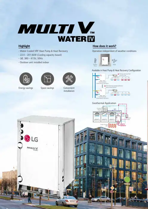
Highlight- Water Cooled VRF Heat Pump & Heat Recovery - 22.4 ~ 201.6kW (Cooling capacity based)- 3Ø, 380 ~ 415V, 50Hz- Outdoor unit installed indoorHow does it work?WindOutdoorT empRoom 1Room 2Room 3Under GroundHEXCoolingT owerWaterPumpControlPanelMUL TI VWATER IV37℃32℃Operation independent of weather conditions Geothermal ApplicationEnergy saving by heatrecovery unitHeating basedSimultaneous operationCooling basedSimultaneous operationExternal energy saving by betweenheat recovery systemAvailable in Heat Pump & Heat Recovery ConfigurationEnergy savings Space savings Convenientinstallation OUTDOOR UNITS092 I 093300MTOTAL PIPING LENGTH40mHeight between IDU ~ IDU50mHeight between IDU ~ IDU40mLongest piping length after 1st branch (Conditional application)150mLongest piping length from ODU ~ IDU (Equivalent)AHUCentral controlBoiler(Space Saving)Cooling T ower(Open type cooling towers can be used.)Independent controlChiller - FCUMulti V Water IVOutdoor Temp OUTDOOR UNITS KEY FEATURESMULTI V WATER IV094 I 095ENERGY SAVINGEconomical, Highly Efficient SystemExtended Compressor Speed 20Hz ~ 140Hz- Rapid operation response- Capable of reaching required temperature quickly - Increase part load efficiencyHiPOR TM (High Pressure Oil Return)- E liminating loss in suction gas by returning oil directly to compressor - Resolve compressor efficiency loss caused by oil returnActive oil control (Oil level sensor)- Oil recovery operation occurs only when required- Enhanced compressor reliability & continuous heating - Oil distribution between compressorsIntegrated Part Load EfficiencyE f f i c i e n c y (E E R )MUL TI V WATER IVMUL TI V WATER II 6% HEX Optimization 4% C ycle CompositionImprovement 1% Inverter Control 1% Active Oil Control 1% HiPOR™5.86.713%※ Comparison between 10HP (28kW) in cooling modeLG’s 4th Generation Inverter Compressor5% HEX Optimization 2% C ycle CompositionImprovement 1% Inverter Control 1% Active Oil Control 1% HiPOR™E f f i c i e n c y (E E R )MUL TI V WATER IVPrevious Model 5.05.510%1,4001,6001,8002,0001,0001,200600800200400P o w e r I n p u t (k W h )MUL TI V WATER IVPrevious Model Economical, Highly Efficient SystemAverage energy saving12%※ Outdoor unit water inlet temperature : 7°C ※ Indoor temperature : 20°C DB / 15°C WB※ Maximum COP Condition : Cooling 40% + Heating 60% operationMaximum COPC O P20406080100Operation Ratio (%)76540Cooling based operation Heating based operationMaximum COP 8.5LG’s key technologies are integrated to inverter compressorWith 4th generation inverter compressor , the Multi V Water IV boasts top-class energy efficiency.WATER SAVINGSNote1. Location : Paris, France2. Office, 68,000m3. Operation time : 1,344 hours (Cooling period)T o t a l W a t e r F l o w (m 3)T o t a l W a t e r F l o w (m 3)Variable Water FlowInverter PumpConstant Water Flow Constant Pump1) Inverter pump with MULTI V Water and variable water flow control kit 2) Constant pump (Step control) with Water cooled VRF Project Example : 63F (Pump : 20,064 LPM, 42.4mAq x 4ea)10 years energy cost ($)• Power consumption rate : 0.13$/kWh• Annual power consumption rate expected to increase by 5%In support of green building initiativesThe world’s first variable water flow control system for water cooled VRF system. LG applied Variable Water Flow Control to optimize water flow control regarding partial cooling or heating load conditions. Because of this it’s also possible to reduce circulation pump energy consumption.Variable Water Flow Control(OPTION)OUTDOOR UNITS KEY FEATURES096 I 097Note1. Data is valid at free field condition2. Data is valid at nominal operating condition3. S ound level will vary depending on a range of factors such as the construction (Acoustic absorption coefficient) of particular room in which the equipment is installed4. Sound level can be increased in static pressure mode or air guide application.Position of Sound Pressure Level MeasuringOptional AccessoriesNote1. These figures assume the following operating conditions:2. Equivalent piping length :7.5m3. Level difference : 0mOperation LimitsCoolingIndoor T emperature (°C WB)HeatingIndoor T emperature (°C DB)I n l e t w a t e r T e m p e r a t u r e (°C )OUTDOOR UNITS TECHNICAL DATAMULTI V WATER IVOUTDOOR UNITS098 I 099o not install the unit at the outdoors. (Installation of the unit outdoors could result in fire or electric shock.) Recommended ambient temperature of outdoor unit is between 0 ~ 40°C.eep the water temperature between 10 ~ 45°C . Standard water supply temperature is 30°C for cooling and 20°C for stablish an anti-freeze plan for the water supply when the e careful of the water purity control . Ensure water purity control to avoid breakdown due to water pipe corrosion. Refer to ‘Standard Table for Water Purity Control’ in PDB (Product he water pressure resistance of the water pipe system of 1.98MPa.lways install a trap so that the drained water does not back nstall a pressure gauge and temperature gauge at the inlet lexible joints must be installed not to cause any leakage nstall a service port to clean the heat exchanger at the each I t is mandatory to install the flow switch to the watercollection pipe system connecting to the outdoor unit. (Flow switch acts as the 1st protection device when the heat water is not supplied.) W hen setting the flow switch, it is recommended to use theproduct with default set value to satisfy the minimum flow rate of this product. (The minimum flow rate range of this product is 50%.) T o protect the water cooling type product, you must installa strainer with 50 mesh or more on the heat watersupply pipe. If not installed, it can result in damage of heat exchanger by the following situation.1) H eat water supply within the plate type heat exchanger is composed of multiple small paths.2) I f you do not use a strainer with 50 mesh or more, alien particles can partially block the water paths.3) W hen running the heater, the plate type heat exchanger plays the role of the evaporator, and at this time, the temperature of the refrigerant side drops to drop the temperature of the heat water supply, which can result in icing point in the water paths.4) A s the heating process progresses, the water paths can be partially frozen to lead to damage in plate type heat exchanger.5) A s a result of the damage of the heat exchanger from the freezing, the refrigerant side and the heat water source side will be mixed to make the product unusable.TECHNICAL DATA098The industrial group Bouygues was established in France in 1952. It now maintains operations in 80 countries and employs more than 131,000 people. In 1988, after two years of construction, the new headquarters for Bouygues Construction was officially opened for business. Named Challenger, the complex became a technological showcase for late 20th century architecture.Site InformationBouygues decided to convert their headquarters into an eco-conscious building by significantly reducing its energy footprint. The LG MULTI V Water system was chosen as the ideal HVAC solution for this project. The system not only saves energy but also reduces water usage as it recycles water in order to regulate the temperature of the building. With LG’s advanced technology, the building’s water consumption was reduced by more than 70 percent.LG SolutionBouygues ChallengerLG MULTI V Water Solution with Geothermal Application.REFERENCE SITEOUTDOOR UNITS REFERENCE SITE100 I 101Note 1. M aximum numbers are prepared based on assumption that all 2.2kW indoor units are connected. The numbers in parentheses means maximum connectable indoor units in accordance with outdoor units combination (160% ~ 200%). The recommended ratio is 130%.2. Due to our policy of innovation some specifications may be changed without notification3. Performances are based on the following conditions- Cooling : Indoor temp 27°C (80.6°F) DB / 19°C (66.2°F) WB, Water inlet temp 30°C (86°F) - Heating : Indoor temp 20°C (68°F) DB, Water inlet temp 20°C (68°F)- Interconnected Pipe Length is 7.5m and difference of Elevation (Outdoor ~ Indoor Unit) is 0m.4. S ound pressure level is measured on the rated condition in the anechoic rooms by ISO 3745 standard.Sound power level is measured on the rated condition in the reverberation rooms by ISO 3741 standard.Therefore, these values can be increased owing to ambient conditons during operation.5. This product contains Fluorinated Greenhouse Gases. (R410A, GWP (Global warming potential) = 2,087.5)6. Add an anti freeze to circulation water when outdoor unit is operating under 10°C (50°F), and change the DIP switch on main PCB. (For more information on installation section.)100OUTDOOR UNITS SPECIFICATIONSNote1. M aximum numbers are prepared based on assumption that all2.2kW indoor units are connected. The numbers in parentheses means maximum connectable indoor units in accordance with outdoor units combination (160% ~ 200%). The recommended ratio is 130%.2. Due to our policy of innovation some specifications may be changed without notification3. Performances are based on the following conditions- Cooling : Indoor temp 27°C (80.6°F) DB / 19°C (66.2°F) WB, Water inlet temp 30°C (86°F)- Heating : Indoor temp 20°C (68°F) DB, Water inlet temp 20°C (68°F)- Interconnected Pipe Length is 7.5m and difference of Elevation (Outdoor ~ Indoor Unit) is 0m.4. S ound pressure level is measured on the rated condition in the anechoic rooms by ISO 3745 standard.Sound power level is measured on the rated condition in the reverberation rooms by ISO 3741 standard.Note1. M aximum numbers are prepared based on assumption that all2.2kW indoor units are connected. The numbers in parentheses means maximum connectable indoor units in accordance with outdoor units combination (160% ~ 200%). The recommended ratio is 130%.2. Due to our policy of innovation some specifications may be changed without notification3. Performances are based on the following conditions- Cooling : Indoor temp 27°C (80.6°F) DB / 19°C (66.2°F) WB, Water inlet temp 30°C (86°F)- Heating : Indoor temp 20°C (68°F) DB, Water inlet temp 20°C (68°F)- Interconnected Pipe Length is 7.5m and difference of Elevation (Outdoor ~ Indoor Unit) is 0m.4. S ound pressure level is measured on the rated condition in the anechoic rooms by ISO 3745 standard.Sound power level is measured on the rated condition in the reverberation rooms by ISO 3741 standard.Note1. M aximum numbers are prepared based on assumption that all2.2kW indoor units are connected. The numbers in parentheses means maximum connectable indoor units in accordance with outdoor units combination (160% ~ 200%). The recommended ratio is 130%.2. Due to our policy of innovation some specifications may be changed without notification3. Performances are based on the following conditions- Cooling : Indoor temp 27°C (80.6°F) DB / 19°C (66.2°F) WB, Water inlet temp 30°C (86°F)- Heating : Indoor temp 20°C (68°F) DB, Water inlet temp 20°C (68°F)- Interconnected Pipe Length is 7.5m and difference of Elevation (Outdoor ~ Indoor Unit) is 0m.4. S ound pressure level is measured on the rated condition in the anechoic rooms by ISO 3745 standard.Sound power level is measured on the rated condition in the reverberation rooms by ISO 3741 standard.Note1. M aximum numbers are prepared based on assumption that all2.2kW indoor units are connected. The numbers in parentheses means maximum connectable indoor units in accordance with outdoor units combination (160% ~ 200%). The recommended ratio is 130%.2. Due to our policy of innovation some specifications may be changed without notification3. Performances are based on the following conditions- Cooling : Indoor temp 27°C (80.6°F) DB / 19°C (66.2°F) WB, Water inlet temp 30°C (86°F)- Heating : Indoor temp 20°C (68°F) DB, Water inlet temp 20°C (68°F)- Interconnected Pipe Length is 7.5m and difference of Elevation (Outdoor ~ Indoor Unit) is 0m.4. Sound pressure level is measured on the rated condition in the anechoic rooms by ISO 3745 standard.Sound power level is measured on the rated condition in the reverberation rooms by ISO 3741 standard.Note1. M aximum numbers are prepared based on assumption that all2.2kW indoor units are connected. The numbers in parentheses means maximum connectable indoor units in accordance with outdoor units combination (160% ~ 200%). The recommended ratio is 130%.2. Due to our policy of innovation some specifications may be changed without notification3. Performances are based on the following conditions- Cooling : Indoor temp 27°C (80.6°F) DB / 19°C (66.2°F) WB, Water inlet temp 30°C (86°F)- Heating : Indoor temp 20°C (68°F) DB, Water inlet temp 20°C (68°F)- Interconnected Pipe Length is 7.5m and difference of Elevation (Outdoor ~ Indoor Unit) is 0m.4. S ound pressure level is measured on the rated condition in the anechoic rooms by ISO 3745 standard.Sound power level is measured on the rated condition in the reverberation rooms by ISO 3741 standard.Note1. M aximum numbers are prepared based on assumption that all2.2kW indoor units are connected. The numbers in parentheses means maximum connectable indoor units in accordance with outdoor units combination (160% ~ 200%). The recommended ratio is 130%.2. Due to our policy of innovation some specifications may be changed without notification3. Performances are based on the following conditions- Cooling : Indoor temp 27°C (80.6°F) DB / 19°C (66.2°F) WB, Water inlet temp 30°C (86°F)- Heating : Indoor temp 20°C (68°F) DB, Water inlet temp 20°C (68°F)- Interconnected Pipe Length is 7.5m and difference of Elevation (Outdoor ~ Indoor Unit) is 0m.4. S ound pressure level is measured on the rated condition in the anechoic rooms by ISO 3745 standard.Sound power level is measured on the rated condition in the reverberation rooms by ISO 3741 standard.Note1. M aximum numbers are prepared based on assumption that all2.2kW indoor units are connected. The numbers in parentheses means maximum connectable indoor units in accordance with outdoor units combination (160% ~ 200%). The recommended ratio is 130%.2. Due to our policy of innovation some specifications may be changed without notification3. Performances are based on the following conditions- Cooling : Indoor temp 27°C (80.6°F) DB / 19°C (66.2°F) WB, Water inlet temp 30°C (86°F)- Heating : Indoor temp 20°C (68°F) DB, Water inlet temp 20°C (68°F)- Interconnected Pipe Length is 7.5m and difference of Elevation (Outdoor ~ Indoor Unit) is 0m.4. S ound pressure level is measured on the rated condition in the anechoic rooms by ISO 3745 standard.Sound power level is measured on the rated condition in the reverberation rooms by ISO 3741 standard.Note1. M aximum numbers are prepared based on assumption that all2.2kW indoor units are connected. The numbers in parentheses means maximum connectable indoor units in accordance with outdoor units combination (160% ~ 200%). The recommended ratio is 130%.2. Due to our policy of innovation some specifications may be changed without notification3. Performances are based on the following conditions- Cooling : Indoor temp 27°C (80.6°F) DB / 19°C (66.2°F) WB, Water inlet temp 30°C (86°F)- Heating : Indoor temp 20°C (68°F) DB, Water inlet temp 20°C (68°F)- Interconnected Pipe Length is 7.5m and difference of Elevation (Outdoor ~ Indoor Unit) is 0m.4. S ound pressure level is measured on the rated condition in the anechoic rooms by ISO 3745 standard.Sound power level is measured on the rated condition in the reverberation rooms by ISO 3741 standard.Note1. M aximum numbers are prepared based on assumption that all2.2kW indoor units are connected. The numbers in parentheses means maximum connectable indoor units in accordance with outdoor units combination (160% ~ 200%). The recommended ratio is 130%.2. Due to our policy of innovation some specifications may be changed without notification3. Performances are based on the following conditions- Cooling : Indoor temp 27°C (80.6°F) DB / 19°C (66.2°F) WB, Water inlet temp 30°C (86°F)- Heating : Indoor temp 20°C (68°F) DB, Water inlet temp 20°C (68°F)- Interconnected Pipe Length is 7.5m and difference of Elevation (Outdoor ~ Indoor Unit) is 0m.4. Sound pressure level is measured on the rated condition in the anechoic rooms by ISO 3745 standard.Sound power level is measured on the rated condition in the reverberation rooms by ISO 3741 standard.Note1. M aximum numbers are prepared based on assumption that all2.2kW indoor units are connected. The numbers in parentheses means maximum connectable indoor units in accordance with outdoor units combination (160% ~ 200%). The recommended ratio is 130%.2. Due to our policy of innovation some specifications may be changed without notification3. Performances are based on the following conditions- Cooling : Indoor temp 27°C (80.6°F) DB / 19°C (66.2°F) WB, Water inlet temp 30°C (86°F)- Heating : Indoor temp 20°C (68°F) DB, Water inlet temp 20°C (68°F)- Interconnected Pipe Length is 7.5m and difference of Elevation (Outdoor ~ Indoor Unit) is 0m.4. S ound pressure level is measured on the rated condition in the anechoic rooms by ISO 3745 standard.Sound power level is measured on the rated condition in the reverberation rooms by ISO 3741 standard.Note1. M aximum numbers are prepared based on assumption that all2.2kW indoor units are connected. The numbers in parentheses means maximum connectable indoor units in accordance with outdoor units combination (160% ~ 200%). The recommended ratio is 130%.2. Due to our policy of innovation some specifications may be changed without notification3. Performances are based on the following conditions- Cooling : Indoor temp 27°C (80.6°F) DB / 19°C (66.2°F) WB, Water inlet temp 30°C (86°F)- Heating : Indoor temp 20°C (68°F) DB, Water inlet temp 20°C (68°F)- Interconnected Pipe Length is 7.5m and difference of Elevation (Outdoor ~ Indoor Unit) is 0m.4. S ound pressure level is measured on the rated condition in the anechoic rooms by ISO 3745 standard.Sound power level is measured on the rated condition in the reverberation rooms by ISO 3741 standard.Note1. M aximum numbers are prepared based on assumption that all2.2kW indoor units are connected. The numbers in parentheses means maximum connectable indoor units in accordance with outdoor units combination (160% ~ 200%). The recommended ratio is 130%.2. Due to our policy of innovation some specifications may be changed without notification3. Performances are based on the following conditions- Cooling : Indoor temp 27°C (80.6°F) DB / 19°C (66.2°F) WB, Water inlet temp 30°C (86°F)- Heating : Indoor temp 20°C (68°F) DB, Water inlet temp 20°C (68°F)- Interconnected Pipe Length is 7.5m and difference of Elevation (Outdoor ~ Indoor Unit) is 0m.4. S ound pressure level is measured on the rated condition in the anechoic rooms by ISO 3745 standard.Sound power level is measured on the rated condition in the reverberation rooms by ISO 3741 standard.Note1. M aximum numbers are prepared based on assumption that all2.2kW indoor units are connected. The numbers in parentheses means maximum connectable indoor units in accordance with outdoor units combination (160% ~ 200%). The recommended ratio is 130%.2. Due to our policy of innovation some specifications may be changed without notification3. Performances are based on the following conditions- Cooling : Indoor temp 27°C (80.6°F) DB / 19°C (66.2°F) WB, Water inlet temp 30°C (86°F)- Heating : Indoor temp 20°C (68°F) DB, Water inlet temp 20°C (68°F)- Interconnected Pipe Length is 7.5m and difference of Elevation (Outdoor ~ Indoor Unit) is 0m.4. S ound pressure level is measured on the rated condition in the anechoic rooms by ISO 3745 standard.Sound power level is measured on the rated condition in the reverberation rooms by ISO 3741 standard.Note1. M aximum numbers are prepared based on assumption that all2.2kW indoor units are connected. The numbers in parentheses means maximum connectable indoor units in accordance with outdoor units combination (160% ~ 200%). The recommended ratio is 130%.2. Due to our policy of innovation some specifications may be changed without notification3. Performances are based on the following conditions- Cooling : Indoor temp 27°C (80.6°F) DB / 19°C (66.2°F) WB, Water inlet temp 30°C (86°F)- Heating : Indoor temp 20°C (68°F) DB, Water inlet temp 20°C (68°F)- Interconnected Pipe Length is 7.5m and difference of Elevation (Outdoor ~ Indoor Unit) is 0m.4. Sound pressure level is measured on the rated condition in the anechoic rooms by ISO 3745 standard.Sound power level is measured on the rated condition in the reverberation rooms by ISO 3741 standard.Note1. M aximum numbers are prepared based on assumption that all2.2kW indoor units are connected. The numbers in parentheses means maximum connectable indoor units in accordance with outdoor units combination (160% ~ 200%). The recommended ratio is 130%.2. Due to our policy of innovation some specifications may be changed without notification3. Performances are based on the following conditions- Cooling : Indoor temp 27°C (80.6°F) DB / 19°C (66.2°F) WB, Water inlet temp 30°C (86°F)- Heating : Indoor temp 20°C (68°F) DB, Water inlet temp 20°C (68°F)- Interconnected Pipe Length is 7.5m and difference of Elevation (Outdoor ~ Indoor Unit) is 0m.4. S ound pressure level is measured on the rated condition in the anechoic rooms by ISO 3745 standard.Sound power level is measured on the rated condition in the reverberation rooms by ISO 3741 standard.。
浅析VRV多联机系统在实际工程中的深化设计1. 引言1.1 VRV多联机系统简介VRV多联机系统是一种集中供热、制冷、通风于一体的空调系统,能够实现不同房间或区域的独立温度控制。
其核心技术是采用一个集中的空气处理机组,通过多个室内机组实现对不同区域的控制,并且可以根据需要自动调整输出功率,实现能耗的优化。
在VRV多联机系统中,每个室内机组都可以单独运行,具有独立的温度控制和定时功能,实现了不同房间或区域的个性化空调需求。
VRV多联机系统还具有节能高效、安装方便、维护简单等优点,逐渐成为居家和商业空调的主流选择。
VRV多联机系统通过其灵活性和高效性,满足了不同用户的空调需求,成为目前市场上备受青睐的空调系统之一。
在实际工程中,对VRV多联机系统进行深化设计是非常必要的,可以进一步提升系统的性能和效率,确保系统在长期运行过程中的稳定性。
1.2 深化设计的必要性深化设计是指在基础设计完成的基础上,进一步优化和完善设计方案,以满足更多的需求和提高系统性能。
在VRV多联机系统的实际工程中,深化设计是十分必要的。
深化设计可以提高系统整体设计的优化。
通过细致的设计和计算,可以减少系统的能耗,提高系统的效率,减少运行成本。
深化设计还可以优化系统的供热供冷效果,提高室内舒适度,提升用户体验。
深化设计可以优化电气连接的设计。
合理的电气连接设计可以提高系统的稳定性,减少故障率,延长系统的使用寿命。
深化设计还可以减少电气线路的长度,减小线路损耗,降低能耗。
深化设计在VRV多联机系统的实际工程中具有重要意义,可以提高系统的性能和效率,降低运行成本,提升用户体验。
未来发展中,需要不断探索和改进深化设计方法,推动VRV多联机系统在实际工程中的应用。
2. 正文2.1 系统整体设计优化系统整体设计优化是VRV多联机系统中非常重要的一环,它涉及到整个系统的性能、效率和稳定性。
在实际工程中,系统整体设计优化可以通过以下几个方面来实现。

两面出风嵌入式的机型比较适合使用在较为狭长的空间,如办公室、走到。
天花板藏风管式可使用在狭长型空间、L型房间、挑高空间、小空间等场合。
薄型天花板藏风管式一般用在宾馆、住宅以及小型办公室。
落地暗藏式一般使用于层高较高、或层高较低但不适合吊顶的空间。
送风方式一般为上送下回。
壁挂式常用于面积较小、不适合做吊顶或不希望装变化的改造项目中。
2.2主机侧设备水源多联机室外机系统与风冷多联机室外机系统基本相同,都是由:换热器、压缩机、气液分离器、油分离器、四通换向阀、电子膨胀阀、电磁阀、压力开关、毛细管、压力传感器等组成。
但是与风冷多联机不同的是,水源多联机制冷时冷却介质是水,而不像传统风冷多联机的室外机那样冷却介质是空气。
因此,冷凝器结构形式不同,风冷多联机系统为强迫对流风冷冷凝器,一般采用肋片管式换热器。
水冷多联机系统为套管式水冷冷凝器。
图二. 肋片管式换热器图三. 板式与套管式换热器表一. 各厂家水源多联机与空气源多联机尺寸对比补水箱、温度计、压力表、阀门、控制系统等。
水源侧系统一般水管路的系统形式有以下几种方式:1)夏季采用水源多联机,冬季采用集中式供暖。
2)夏季冬夏均采用水源多联机。
3)如过渡季节需要同时供热、供冷,水源侧系统可采用热回收式系统,如图四。
图四. 水源侧热回收型系统3水源多联机设计要点水源多联机空调系统主要包括冷媒系统设计、水系统设计、新风系统设计等,主要的设计步骤:1)材料收集,确定初步方案2)确定室机形式和容量(可室外机容量)3)新风系统设计4)室外机位置及管道布置5)水源侧系统设计3.1室侧设计设计步骤:1)设计条件确定和冷热负荷计算2)暂定室机容量和形式其中局部阻力损失=局部阻力系数*动压以上阻力之和可取1.1保险系数4案例分析水源多联机的冷热源方式较多,本文将通过两个案例介绍。
4.1骋望骊都项目本工程为骋望置业骋望骊都华庭住宅楼小区,总建筑面积为22万平方米,此次设计为会所,主要由活动室、茶室、健身房、泳池等组成。
关于水冷多联空调系统设计的探讨摘要:多联机是一种新型的空调系统,在我国得到了广泛的应用,它具有系统简单、舒适节能、设计灵活、安装简便而且可靠性较高等优点,已经成为了国内的空调领域当中一种较为重要的空调系统。
通过与风机多联空调系统的对比,结合工程案例,总结出水冷多联空调系统的一些特点,以及设计工程中的一些注意事项。
关键词:风冷多联空调系统水冷多联空调系统特点注意事项1.水冷多联空调系统的原理多联机空调系统按外机冷却形式主要分为风冷多联机和水冷多联机两种。
这两种形式的空调系统的循环原理大致相同,其工作原理是:由控制系统采集室内舒适性参数、室外环境参数和表征制冷系统运行状况的状态参数,根据系统运行优化准则和人体舒适性准则,通过变频等手段调节压缩机输气量,并控制电子膨胀阀等一切可控部件,保证室内环境的舒适性,并使空调系统稳定工作在最佳工作状态。
两者主要不同的地方就是室外机的换热介质存在着一定的差异。
在水冷多联空调系统运行的时候,风冷多联的室外机的换热介质是空气,而水冷多联的室外机系统的换热介质是水。
由于水冷多联空调系统有独特的换热器结构,在对相同热量进行交换时就会让水冷换热器的面积减少很多。
所以,水冷多联系统的室外机的体积相对来说比较小,安装比较方便灵活。
2.水冷多联空调系统的特点2.1传统的风冷多联机由于连管长度限度,无法应用到高落差的建筑物上,而水冷多联空调以水管连接,基本无管长限制,尤其适用于高层建筑或大型楼宇。
同时由于采用水作为冷热源,主机无需与室外空气直接换热,因此基本不用考虑散热问题,可方便的设置在当层或者集中放置在设备机房内,大大的提高了建筑的空间利用率,且无需开百叶,不会对建筑外立面的美观性造成影响,震动以及噪音小。
2.2水冷多联空调系统采用水来冷却,冷凝温度低,COP能效高达5.8,节能效果明显,运行费用低。
2.3水冷多联空调系统可实现内外区分,可满足现代建筑物在同一时间不同区域制热和制冷的需求,系统通过温控阀切换其工作状态;当系统冷负荷为主要负荷时,自动启动冷却塔进行散热;当系统热负荷为主要负荷时,自动开启锅炉提供热源;当冷热负荷基本相等时,冷却塔和锅炉都无须开启,即通过热回收便可满足空调要求,避免产生多余的电费,并且当冷热平衡时,热回收的效率最大。
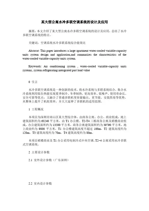
某大型公寓水冷多联空调系统的设计及应用摘要:本文介绍了某大型公寓水冷多联空调系统的设计及应用,总结了水冷多联空调系统的特点。
关键词:空调系统水冷多联系统综合能效比Abstrcat: This paper introduces a large apartment water-cooled variable-capacity units system design and application,and summarizes the characteristics of the water-cooled variable-capacity units system.Keywords: Air conditioning system , water-cooled variable-capacity units systems, system refrigerating intergrated part load value0 引言水冷多联空调系统是一种创新的技术,将水冷系统与多联系统结合,集合水冷系统利用低位热能实现夏季制冷、冬季制热,更高效率、低噪声、使用寿命长、安全可靠等优点;又融合了普通多联机变容量输出、更节能、安装简易等优势,从整体上提升了机组效率,并大大延伸了多联机的适用范围。
1 工程概况本项目为深圳市南山区某大型综合体,由商务公寓、办公、商业组成,地上建筑面积约为63240平方米,由T1办公楼、T2-T4三栋商务公寓及裙楼商业组成,办公建筑面积约为13500平方米,商务公寓建筑面积约为39790平方米,地上商业约为9800平方米,T1办公楼建筑高度不超过100m,T2建筑高度约为120m,T3建筑高度约为70m,T4建筑高度约为80m。
本项目裙楼商业及T1办公采用电制冷式中央空调,T2~4公寓采用水冷多联式空调系统。
2 主要设计参数2.1 室外设计参数(广东深圳)2.2 室内设计参数根据以上室内外空气计算参数、建筑围护结构的热工参数等,利用专业的空调负荷计算软件,根据逐时逐项负荷计算出该建筑各层的冷热负荷详见下表:3 空调系统选择及配置本项目虽属于夏热冬暖地区,但根据业主要求,T2~4公寓均要求夏季制冷,冬季供热,充分确保室内环境的舒适性,在此前提下采用节能、环保、智能化管理的设备。
多联机设计方案概述多联机系统是一种能够同时连接多个室内机和一个室外机的空调系统。
通过这个系统,用户可以根据需要将冷气输送到不同的房间或空间中。
本文将介绍多联机设计方案的原理、优势和应用。
原理多联机系统由室内机、室外机和管道组成。
室内机通过管道与室外机相连,室外机负责将热量排放到室外,而室内机则将冷气输送到需要冷却的房间或空间中。
通过这种连接方式,用户可以通过一个室外机控制多个室内机的运行,实现分区控制。
优势多联机系统相比传统的单个空调系统具有许多优势。
首先,它能够满足不同房间或空间的不同冷气需求,提高了冷却的灵活性和舒适度。
其次,多联机系统可以实现个别室内机的独立运行,避免了因冷气需求不同而导致的能源浪费。
此外,多联机系统还可通过合理的管道设计来减少能源损失,提高整体能效。
应用多联机系统广泛应用于住宅、商业和办公场所等场合。
在住宅方面,它可以满足不同房间的冷气需求,使每个房间都能保持舒适的温度。
在商业方面,多联机系统可以根据需要提供不同房间或区域的冷却和制冷,适用于酒店、购物中心和办公大楼等场所。
此外,多联机系统还可以用于医院、学校和实验室等特殊场所,满足不同空间的特殊冷却需求。
设计方案在设计多联机系统时,需要考虑以下几个方面。
首先,根据使用场所的不同,确定需要连接的室内机的数量和类型。
然后,确定室外机的容量和管道的布置,以确保系统能够满足整个空间的冷气需求。
此外,还需考虑管道的长度、直径、绝缘和散热等设计要素,以确保系统的运行效果和能耗控制。
最后,要合理安排控制系统,确保用户方便操作和使用。
总结多联机系统通过连接多个室内机和一个室外机,可以实现分区控制和个别运行,提高了冷却的灵活性和舒适度。
它在住宅、商业和办公场所等各个方面都有广泛的应用,并且可以根据实际需求进行设计和布置。
在设计多联机系统时,需要充分考虑不同房间或区域的冷气需求,并合理安排系统的容量、管道和控制等设计要素。
通过优化设计方案,多联机系统可以提高能效,节约能源,并提供更好的使用体验。
VRF(变制冷剂流量系统)设计应注意的问题摘要根据个人近年来的工程设计体会,觉得以下几个方面对VRF空调的实际应用带来很大的影响,设计时应给予充分的注意。
关键词VRF空调系统;设计;注意问题随着社会的发展,城市建设的不断深入,建筑物对空调系统的设计要求越来越高,近几年来,VRF空调系统由于它具有节能、环保、控制方便等特点得到了越来越多的甲方、设计人员的亲睐,但我们设计人员在工程设计过程中尤其要注意本文所讲述的这几个问题,根据不同工程加以具体分析,设计出合理、节能的VRF空调系统方案。
1 室内机选型布置方面1)室内机的选型。
VRF空调系统室内机的大小、形式、布置位置均直接影响空调气流组织、空调系统的造价及空调使用效果。
在选用布置室内机时,应充分掌握各种形式室内机的特点,扬长避短,根据室内空间大小及装饰要求合理选择室内机的形式和大小,如果选择不当不仅造成浪费,而且影响空调效果,在选择时应配合装饰要求及吊顶内管线布置情况决定选择嵌入式还是风管式。
如果室内平面成正方形,可选用四面出风嵌入式;如果房间成狭长形,可选用两面或单面出风嵌入式。
但要注意层高较高时,若选用嵌入式,会出现冬季供热时热风不能送达工作区域。
如果室内空间较大、层高较高可选用高、中静压大容量的风管式室内机,尽可能减少设备的使用数量,降低设备造价;对噪音要求比较高的,诸如办公室等房间,采用低静压、容量较小的风管式室内机。
如果室内无吊顶可选用明装式的吊顶机、挂壁机等,也可以采用小型风管式落地安装的方法,但要注意管路的隐蔽处理以及冷凝水的排放。
2)室内机的布置。
室内机的布置要在首先充分保证空调效果的情况下满足装修设计要求,保证足够的安装(冷媒、冷凝水、电源管路、风管等)空间,保证足够的维护空间。
方式一:侧送下回式。
优点:吊顶空间小,装潢自由度高,噪音低,适合卧室使用,可充分利用卫生间或壁橱旁边的空间。
方式二:上送上回式。
优点:气流分布均匀,空调舒适性高,特别是制热效果可以得到更好的保证,适合较高的空间或斜屋顶房间使用。
第一部分技术规格及要求一、概要此份技术规格书是招标文件的一部分,包括空调的详细规格、条款和资料。
投标人须根据各自的技术和商务优势对全部项目进行投标。
买方有权根据工程需要选择投标人的中标范围。
二、工地条件所有合同中提供的设备应能符合下列但不仅限于以下的环境条件。
2.1适应性要求:工况:水冷VRF:室内:制冷:干球温度:27℃,湿球温度:19℃制热:干球温度:20℃制冷:进水温度:20℃制热:进水温度:15℃2.2电源条件所有提供的设备和元器件的安装须符合和适应下列条件,不包括在另行条文中的说明。
电压:~380V,3相5线,50Hz;~220V,单相,50Hz电压波动:-10%~+10%接地电阻要求:≤4欧姆2.3抗地震要求:所有提供的设备,须适应6度地震烈度,建筑结构正常的前提下,能正常运行。
三、标准和规范3.1中国国家标准及其它被普遍认可的中国标准如:GB9237-88 制冷设备通用技术规范JB6917-1988 制冷装置用压力容器3.2被普遍认可的其他国家标准这些标准应为最新标准,投标人应及时提供给招标人(国外标准应翻译成中文)。
3.3投标人遵守不仅限于此规格书中的标准时,要求及时解释清楚,获得招标人认可后,投标人推荐的标准和制造规范等效或适用于此技术规格书,招标人有可能接受。
投标人须阐明其替换的标准或其实际使用的标准,并提供所推荐的标准和制造规范。
四、技术规格和要求注:以下所有技术规格均来自设计图纸。
考虑到有些投标人的空调设备配置与设计有一定偏离(如没有偏离,则必须按设计进行配置),我们允许这些投标人对所投的空调设备投标配置有一定的正偏离,且并不会导致评标时技术扣分。
4.1 可变冷媒流量多联式冷暖型空调技术规格和要求4.1.1技术设计参数详见施工图:设施-18A(VRF系统设备材料表)。
4.1.2 技术要求投标人应根据本招标文件提供的文字要求及图纸,设计生产、供应相应的设备,并负责安装调试。
了解并应用VRF空调机组VRF与VRV的关联与区别:应该来说变频多联机(常见的大金“VRV”)也是VRF 的一类分支。
VRF就是变冷媒流量的系统,又称为制冷剂系统,Variable (可变的) Refrigerant (冷媒) F–Flow/Volume (流量),而VRV专指大金的直流变频系统,是大金申请的专利。
严格上说,别的品牌的变频多联机系统就不能再叫VRV,当然VRF系统除了直流变频还有交流变频,还有数码涡旋等不同压缩机形式,这些制冷剂系统都统称为VRF系统。
空调用能源主要用于热源机和热搬送,因此要解决空调的能耗问题,就需要从减少热源能耗及减少热搬送能耗两大方面着手。
减少空调耗能的形式:空调用能源主要用于热源机和热搬送,因此要解决空调的能耗问题,就需要从减少热源能耗及减少热搬送能耗两大方面着手。
1、减少热源机用耗能:1)采用节能的直接膨胀式系统直接膨胀式系统因比间接膨胀式系统减少了一次热交换而达到了节能的目的。
空调系统按照热源输出形式可分为两种:直接膨胀系统,冷媒在室内机的蒸发器内直接膨胀后冷却空气的直接膨胀方式。
间接膨胀系统,冷媒冷却过的水被送往各个房间与室内空气进行热交换的间接膨胀方式。
2)充分利用变频技术的节能性变频技术的应用使得压缩机可以根据室内机的实际需求进行能力输出,以满足空调部分负荷运转等状态下的能力需求。
相对于不根据实际能力变化而改变压缩机输出的定频空调,变频空调更加节能,再此基础上舒适度也大大提高。
2、减少热搬送用耗能:1)采用热搬送动力为零的直接膨胀式系统直接膨胀式系统不像间接膨胀式系统需要空气、水等热搬送动力。
如:采用直接膨胀式技术的VRF系统而言,其系统组成仅为室内机、室外机以及冷媒配管(如下图所示)。
VRF系统于水冷和风冷系统相比无需其他热搬送元件(如下图所示),当然也就不存在这部分的能耗。
即VRF系统是热搬送耗能为零的,顺应现在节能需求的产品。
2)采用高效率的热搬送媒介为了达到同一的制冷/制热量时,由于采用不同物理特性的热搬送媒介,其所需要的能耗是不一样的。