vhdl按键消抖程序
- 格式:docx
- 大小:21.46 KB
- 文档页数:6
基于VHDL的开关消抖电路的研究王彩君;周开邻;黄智进【摘要】介绍了3种开关消抖方案的工作原理,给出了基于VHDL的相关实现程序和测试结果,并就结构、抗干扰、时序配合等方面对电路性能进行分析讨论.电路实用性强,对学生设计电路有一定的启发引导.【期刊名称】《实验科学与技术》【年(卷),期】2010(008)002【总页数】3页(P1-2,11)【关键词】开关;消抖;VHDL语言【作者】王彩君;周开邻;黄智进【作者单位】云南大学物理科学技术学院,昆明,650091;云南大学物理科学技术学院,昆明,650091;云南大学物理科学技术学院,昆明,650091【正文语种】中文【中图分类】TN79;TP39机械式开关、按钮或键盘由于其低成本、高可靠性作为输入控制器件而被广泛应用于电子设备中。
但是,由于此类开关机械弹性的作用,在开关闭合或断开的瞬间会伴随着一连串的随机抖动,使某些电路误动作,造成整个系统工作的异常。
因此,在开关信号送入此类电路前,必须对其进行预处理,以消除开关的抖动。
本文归纳了 3种基于VHDL(VHSI C Hardware Description Langaage)的实用开关消抖方案的工作原理、实体结构以及各自特点,希望对本科学生进行电子设备类的毕业设计起到一定的启发引导作用。
基于VHDL的开关消抖方案有很多,但按工作原理,可将它们归纳为“电平检测消抖法”、“定时检测消抖法”和“脉宽检测消抖法”3大类。
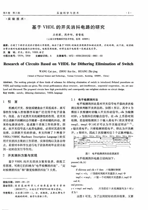
2.1 电平检测消抖法电平检测消抖法是对开关信号电平值的多次检测比较来判断开关状态的。
如图 1所示,其中 k为模拟 2次按键时的输入开关抖动信号;clk为检测时钟;y为消抖后的输出信号。
在 clk上升沿时刻检测,若连续检测到 2个输入高电平 (依次寄存在tmep2、tmep1中)时才可认为开关稳定闭合[1-2], y输出高电平;只要检测到低电平,即认为开关断开,y即回 0。
因此 2次按键对应 2个正脉冲输出。
这学期的EDA课程设计有涉及到一个按键信号稳定的问题,虽然就算没有这块处理,最后成绩只会扣3分,但自己觉得像LED亮度变化,数字钟设置这些功能,如果没有加进一个稳定按键信号的模块,根本不能算是已实现的功能。
按键消抖的程序在网上有几种可供选择,但这里只讨论一种,本人觉得简单得来又比较强大的一种。
其实消抖的原理就是把一个按键周期内所输入的所有有效信号,包括那些毛刺,处理成一个脉冲输入。
能达到这点,就可以实现消抖功能了。
功能的源代码:代码中的 key 是按键输入,count 是自定义的计数器,N的值可以根据需要结合时钟频率设置,如果只是想达到按键一次输入一个脉冲的效果,建议 count 的时长设为 5ms,key_en 是处理完后输出的单个脉冲,至于有效信号是 '0' 还是'1' ,这要看板上的电路设计了。
此代码中是 '0' 为有效信号。
不要怀疑这段代码有错,理清逻辑后再套用,如果弄不明白什么原理,建议还是别用,用了可能会更糟糕。
要注意的是一个 process 中只能有一个时钟信号,否则很容易出错,就算编译通过,实际操作还是不行。
所以如果要对多个按键消抖,一定要在 "if clk'event and clk='1' then" 语句的内部增加,别重新设置一个 clk'event 。
还有就是按键的消抖功能块最好用单独的 process 运行,将 key_en 设置成新的按键输入信号,而实际的输入信号 key 只在按键消抖的process 中读入。
之所以说这种消抖方法简单得来又比较强大,是因为这方法不需要用到什么状态机、component 之类较高级点的东西,只需要多个 process 即可;另外这种方法还有其他的拓展用途,比如可以利用这个 count 延时周期设置一个短按键和长按键的识别,实现长按此键切换或者 reset 等等的功能,这里不详细解释。
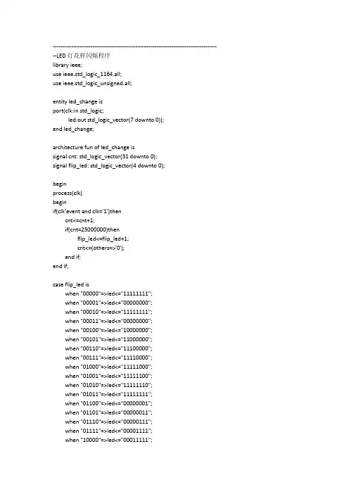
--------------------------------------------------------------------------------------- --LED灯花样闪烁程序library ieee;use ieee.std_logic_1164.all;use ieee.std_logic_unsigned.all;entity led_change isport(clk:in std_logic;led:out std_logic_vector(7 downto 0));end led_change;architecture fun of led_change issignal cnt: std_logic_vector(31 downto 0);signal flip_led: std_logic_vector(4 downto 0);beginprocess(clk)beginif(clk'event and clk='1')thencnt<=cnt+1;if(cnt=25000000)thenflip_led<=flip_led+1;cnt<=(others=>'0');end if;end if;case flip_led iswhen "00000"=>led<="11111111";when "00001"=>led<="00000000";when "00010"=>led<="11111111";when "00011"=>led<="00000000";when "00100"=>led<="10000000";when "00101"=>led<="11000000";when "00110"=>led<="11100000";when "00111"=>led<="11110000";when "01000"=>led<="11111000";when "01001"=>led<="11111100";when "01010"=>led<="11111110";when "01011"=>led<="11111111";when "01100"=>led<="00000001";when "01101"=>led<="00000011";when "01110"=>led<="00000111";when "01111"=>led<="00001111";when "10000"=>led<="00011111";when "10001"=>led<="00111111";when "10010"=>led<="01111111";when "10011"=>led<="11111111";when "10100"=>led<="00000000";when others =>led<="ZZZZZZZZ";end case;if(flip_led>"10100")thenflip_led<="00000";end if;end process;end fun;--拨码开关控制LED程序library ieee;use ieee.std_logic_1164.all;entity switch_led isport(key : in std_logic_vector(1 downto 0);led : out std_logic_vector(7 downto 0)); --八个led灯end switch_led;architecture fun of switch_led isbeginprocess(key)begincase key iswhen "00" => led <="00000000"; -- // "0"when "01" => led <="00001111"; -- // "1"when "10" => led <="11110000"; -- // "2"when "11" => led <="11111111"; -- // "3"when others => led <="ZZZZZZZZ";end case;end process;end;--按键消抖控制LED程序library ieee;use ieee.std_logic_1164.all;use ieee.std_logic_arith.all;use ieee.std_logic_unsigned.all;entity stable_key isport(clk :in std_logic;key_in:in std_logic;key_out: out std_logic);end ;architecture fun of stable_key issignal cnt : integer range 0 to 1999999;signal key ,key_d : std_logic;beginprocess(clk)beginif clk'event and clk='1' thenif key /= key_in then -----键值变化开始计时10ms key_d <= key_in;cnt <= 0;elsif cnt=1999999 then ---10mskey_out <= not key_d;cnt <= 0;elsecnt <= cnt + 1 ;end if ;key<= key_in;end if ;end process;end ;--蜂鸣器电子琴程序library ieee;use ieee.std_logic_1164.all;entity digital_piano isport(key : in std_logic_vector(7 downto 0); --定义8个按键key1~key8clk : in std_logic; --时钟输入端50Mhzbeep: out std_logic); --蜂鸣器输出端end digital_piano;architecture fun of digital_piano issignal freq : integer range 0 to 50000;signal beep_reg: std_logic;beginbeep_process: process(clk,freq) --分频进程--本工程内核心进程,计数器的大小由counter决定variable cnt : integer range 0 to 50000;beginif clk'event and clk='1' thenif cnt < freq thencnt := cnt + 1;elsecnt := 0 ;beep_reg <=not beep_reg;end if;end if;end process beep_process;freq_process: process(key)begincase key iswhen "11111110" => freq <= 47774; ---------------------------------counter 计算公式:中音do的频率为523.3hz,为了在上个beep_pro进程中得到523的频率counter= 50*1000000/(523*2)when "11111101" => freq <= 42568; --中音re的频率为587.3hzwhen "11111011" => freq <= 37919; --中音mi的频率为659.3hzwhen "11110111" => freq <= 35791; --中音fa的频率为698.5hzwhen "11101111" => freq <= 31888; --中音sol的频率为784hzwhen "11011111" => freq <= 28409; --中音la的频率为880hzwhen "10111111" => freq <= 25309; --中音si的频率为987.8hzwhen "01111111" => freq <= 23912; --高音do的频率为1045.5hzwhen "01111101" => freq <= 21282; --高音re的频率为1174.7hzwhen "01111011" => freq <= 18961; --高音mi的频率为1318.5hzwhen "01110111" => freq <= 17897; --高音fa的频率为1396.9hzwhen "01101111" => freq <= 15944; --高音sol的频率为1568hzwhen "01011111" => freq <= 14205; --高音la的频率为1760hzwhen "00111111" => freq <= 12605; --高音si的频率为1975.5hzwhen others => freq <= 0;end case;end process freq_process;beep <= beep_reg;end;--数码管静态扫描library ieee;use ieee.std_logic_1164.all;use ieee.std_logic_arith.all;use ieee.std_logic_unsigned.all;entity static_segled isport(clk : in std_logic;data:out std_logic_vector(7 downto 0);sel:out std_logic_vector(7 downto 0));end ;architecture fun of static_segled issignal num : std_logic_vector(3 downto 0);signal cnt : integer range 0 to 12499999 ;beginsel <= "00000000"; --静态显示,全部位选中process(clk)beginif clk'event and clk='1' then --每四秒改变一次数字if cnt=12499999 thencnt<=0;num<= num + 1;elsecnt<= cnt + 1 ;end if ;end if ;end process;process(num)begincase num iswhen "0000" => data<=x"c0"; -- // "0"when "0001" => data<=x"f9"; -- // "1"when "0010" => data<=x"a4"; -- // "2"when "0011" => data<=x"b0"; -- // "3"when "0100" => data<=x"99"; -- // "4"when "0101" => data<=x"92"; -- // "5"when "0110" => data<=x"82"; -- // "6"when "0111" => data<=x"f8"; -- // "7"when "1000" => data<=x"80"; -- // "8"when "1001" => data<=x"90"; -- // "9"when "1010" => data<=x"88"; -- // "a"when "1011" => data<=x"83"; -- // "b"when "1100" => data<=x"c6"; -- // "c"when "1101" => data<=x"a1"; -- // "d"when "1110" => data<=x"86"; -- // "e"when "1111" => data<=x"8e"; -- // "f"when others => data<=x"ff";end case;end process;end ;--数码管动态扫描library ieee;use ieee.std_logic_1164.all;use ieee.std_logic_arith.all;use ieee.std_logic_unsigned.all;entity dynamic_segled isport(clk : in std_logic;data: out std_logic_vector(7 downto 0);sel:out std_logic_vector(7 downto 0) );end ;architecture fun of dynamic_segled issignal cnt: integer range 0 to 62449;signal flip_led: integer range 0 to 7;beginprocess(clk)beginif clk'event and clk='1' then ----- 动态扫描if cnt=62499 thencnt<=0;flip_led<=flip_led+1; -- 数据改变elsecnt<=cnt + 1;end if ;end if ;end process;process(flip_led)begincase flip_led is ---译码显示when 0 =>sel<="01111111";data<=x"c0";when 1 =>sel<="10111111";data<=x"f9";when 2 =>sel<="11011111";data<=x"a4";when 3 =>sel<="11101111";data<=x"b0";when 4 =>sel<="11110111";data<=x"99";when 5 =>sel<="11111011";data<=x"92";when 6 =>sel<="11111101";data<=x"82";when 7 =>sel<="11111110";data<=x"f8";when others=>sel<="11111111";data<=x"ff"; end case;end process;end ;。
2.2系统的输入、输出端口以及寄存器清单及说明:CLK 输入时钟方波信号端口KIN 键盘按键输入端口KOUT 键盘完整编码码值输出端口(七位二进制数)KOUT1 扫描信号输出端口(三位二进制数)SIN 键盘消抖输入端口(七位二进制数)SOUT 键盘消抖输出端口(七位二进制数)LIN 键盘按键编码模块输入端口(七位二进制数)DF 数字按键标志寄存器FF 功能按键标志寄存器ND 数字按键识别编码寄存器NF 功能按键识别编码寄存器LOCK 电子密码锁上锁状态标志寄存器LOCK1 电子密码锁报警状态标志寄存器UNLOCK 电子密码锁开锁状态标志寄存器NULL1 电子密码锁无密码状态标志寄存器DATA 电子密码锁数码显示数据寄存器CAT 电子密码锁数码显示位选寄存器DISPLAY 电子密码锁数码显示段选寄存器(十七位二进制数)NUM0、NUM1、NUM2、NUM3数码显示中分位显示数据寄存器DISNUM 数码显示段选数据寄存器I1 数码显示计数器SCANS 键盘扫描中按键完整编码寄存器SCAN 键盘扫描寄存器CNT 键盘消抖计数器SIN1 键盘按键键值寄存器I 键盘扫描计数器DF1 数字按键状态标志寄存器ACC 键盘数字输入暂存器T 报警计数器REG 电子密码锁密码存储器NC 计数器1键盘输入扫描部分源程序LIBRARY IEEE;USE IEEE.STD_LOGIC_ARITH.ALL;USE IEEE.STD_LOGIC_UNSIGNED.ALL;USE IEEE.STD_LOGIC_1164.ALL;ENTITY kbscan1 isPORT(clk:in STD_LOGIC;kin:in STD_LOGIC_VECTOR(3 DOWNTO 0);---PC7-PC4 kout:out STD_LOGIC_VECTOR(7 downto 0);--PC3--PCkout1: out STD_LOGIC_VECTOR(3 downto 0));end kbscan1;architecture a of kbscan1 issignal scans: std_logic_vector(7 downto 0);--PC7--PC0signal scan : std_logic_vector(3 downto 0);--PC3--PC0signalt :integer range 0 to 140;signal sin1:std_logic_vector(3 downto 0);signal i:integer range 0 to 3;beginscans<=scan& kin;kout<=scans;kout1<=scan;process(clk)beginif(falling_edge(clk))thenif(i=3)theni<=0;elsei<=i+1;end if;case i iswhen 0=>scan<="0001";when 1=>scan<="0010";when 2=>scan<="0100";when 3=>scan<="1000";end case;end if;end process;End a;2键盘输入消抖部分源程序LIBRARY IEEE;USE IEEE.STD_LOGIC_1164.ALL;ENTITY xiaodou isPort(clk :in STD_LOGIC;sin:in std_logic_vector(7 downto 0);sout:out std_logic_vector(7 downto 0));end xiaodou;architecture behavioral of xiaodou issignalt :integer range 0 to 120;signal sin1:std_logic_vector(7 downto 0);beginprocess(clk)beginsin1<=sin;if (rising_edge(clk))thenif(sin1=sin)thent<=cnt+1;elsesin1<=sin;t<=0;end if;if(cnt=120)thensout<=sin;t<=0;end if;end if;end process;end behavioral;3键盘输入编码部分源程序LIBRARY IEEE;USE IEEE.STD_LOGIC_ARITH.ALL;USE IEEE.STD_LOGIC_UNSIGNED.ALL;USE IEEE.STD_LOGIC_1164.ALL;ENTITY bianma isPORT(clk:in STD_LOGIC;lin:in STD_LOGIC_VECTOR(7 DOWNTO 0);---PC7-PC4DF,FF: out std_logic;nd,nf:BUFFER std_logic_vector(3 downto 0));end bianma;architecture b of bianma isbeginprocess(clk)beginif clk'event and clk='1' thencase lin iswhen"10000001"=>ND<="0000";--0when"00010001"=>ND<="0001";--1when"00010010"=>ND<="0010";--2when"00010100"=>ND<="0011";--3when"00100001"=>ND<="0100";--4when"00100010"=>ND<="0101";--5when"00100100"=>ND<="0110";--6when"01000001"=>ND<="0111";--7when"01000010"=>ND<="1000";--8when"01000100"=>ND<="1001";--9when others =>ND<="1111";END CASE;END IF;IF CLK'EVENT AND CLK='1' THENCASE LIN ISwhen"00011000"=>NF<="0001";--qingchuwhen"00101000"=>NF<="0010";--querenwhen"01001000"=>NF<="0011";--shangsuowhen"10001000"=>NF<="0100";--kaisuowhen"10000100"=>NF<="0101";--wangjimimawhen"10000010"=>NF<="0111";--genggaimimaWhen others =>NF<="1000";END CASE;END IF;END PROCESS;DF<=NOT(ND(3) AND ND(2) AND ND(1) AND ND(0));FF<=NF(2) OR NF(1) OR NF(0);end b;4 电子密码锁的控制部分程序DF 数字按键标志寄存器FF 功能按键标志寄存器ND 数字按键识别编码寄存器NF 功能按键识别编码寄存器LOCK 电子密码锁上锁状态标志寄存器LOCK1 电子密码锁报警状态标志寄存器UNLOCK 电子密码锁开锁状态标志寄存器NULL1 电子密码锁无密码状态标志寄存器DATA 电子密码锁数码显示数据寄存器LIBRARY IEEE;USE IEEE.STD_LOGIC_1164.ALL;ENTITY kongzhi ISPORT(CLK: IN STD_LOGIC;DF,FF: in STD_LOGIC;ND,NF:in STD_LOGIC_VECTOR(3 downTO 0);LOCK,LOCK1,UNLOCK:buffer STD_LOGIC;NULL1: buffer STD_LOGIC;DA TA: out STD_LOGIC_VECTOR(15 downTO 0) );END kongzhi;ARCHITECTURE V1 OF kongzhi ISsignal i1:integer range 0 to 3;signal df1:std_logic;signal ACC: STD_LOGIC_VECTOR(15 DOWNTO 0);signal t: INTEGER RANGE 0 TO 2;signal REG:STD_LOGIC_VECTOR(15 downTO 0);signal NC,A:INTEGER RANGE 0 TO 3;beginPROCESS(FF,DF)ISBEGINif rising_edge(clk) thenIF FF='1'THENIF NF="0001"THENACC<="0000000000000000";NC<=0;END IF;ELSEdf1<=df;IF df1='0'and DF='1' THENIF NC<4 THENACC<=ACC(11 DOWNTO 0)&ND;NC<=NC+1;END IF;END IF;END IF;IF FF='1' THENIF NF="0011" THENREG<=ACC;LOCK<='0';UNLOCK<='1';LOCK1<='1';NULL1<='1';elseIF NF="0100" THENIF REG=ACC THENLOCK<='1';UNLOCK<='0';LOCK1<='1';NULL1<='1';ELSELOCK<='0';UNLOCK<='1';IF t=2 THENREG<="1000100010001000";LOCK1<='0';lock<='1';unlock<='1';null1<='1';t<=0;ELSEt<=t+1;END IF;END IF;elseIF NF="0101" THENREG<="1000100010001000";LOCK<='0';UNLOCK<='1';LOCK1<='1';NULL1<='1';elseIF NF="0111" THENIF UNLOCK='1' THENIF REG=ACC THENREG<="0000000000000000";NULL1<='0';LOCK<='1';LOCK1<='1';UNLOCK<='1';END IF;END IF;elseIF NF="0010" THENREG<=ACC;NULL1<='1';LOCK<='0';LOCK1<='1';UNLOCK<='1';END IF;end if;end if;end if;end if;end if;end if;END PROCESS;DA TA<=ACC;END ARCHITECTURE V1;CAT 电子密码锁数码显示位选寄存器DISPLAY 电子密码锁数码显示段选寄存器(十七位二进制数)DISPLAY 电子密码锁数码显示段选寄存器(十七位二进制数)NUM0、NUM1、NUM2、NUM3数码显示中分位显示数据寄存器DISNUM 数码显示段选数据寄存器I1 数码显示计数器5电子密码锁的数码显示模块源程序LIBRARY IEEE;USE IEEE.STD_LOGIC_1164.ALL;ENTITY LEDXIANSHI ISPORT(CLK :IN STD_LOGIC;DA TA: in STD_LOGIC_VECTOR (15 DOWNTO 0);CA T:OUT STD_LOGIC_VECTOR(0 TO 3);DISPLAY:OUT STD_LOGIC_VECTOR(16 DOWNTO 0));END LEDXIANSHI;ARCHITECTURE BEHA VIORAL OF LEDXIANSHI ISSignal NUM0,NUM1,NUM2,NUM3: STD_LOGIC_VECTOR(3 DOWNTO 0);SIGNAL DISNUM:STD_LOGIC_VECTOR(16 DOWNTO 0);SIGNAL I1:INTEGER RANGE 0 TO 3;BEGINNUM0<=DATA(3 DOWNTO 0);NUM1<=DATA(7 DOWNTO 4);NUM2<=DATA(11 DOWNTO 8);NUM3<=DA TA(15 DOWNTO 12);DISPLAY<=DISNUM;PROCESS(CLK)BEGINIF(RISING_EDGE(CLK))THENIF(I1=3)THENI1<=0;ELSEI1<=I1+1;END IF;END IF;END PROCESS;PROCESS(I1)BEGINCASE I1 ISWHEN 0=>CA T<="1110";CASE NUM0 ISWHEN "0000"=>DISNUM<="00000000011111111";WHEN "0001"=>DISNUM<="00000000000001100";WHEN "0010"=>DISNUM<="00001000101110111";WHEN "0011"=>DISNUM<="00001000100111111";WHEN "0100"=>DISNUM<="01001010110000000";WHEN "0101"=>DISNUM<="00001100110111011";WHEN "0110"=>DISNUM<="00001000111111011";WHEN "0111"=>DISNUM<="00000000000001111";WHEN "1000"=>DISNUM<="00001000111111111";WHEN "1001"=>DISNUM<="00001000110111111";WHEN OTHERS=>DISNUM<=NULL;END CASE;WHEN 1 => CAT<="1101";CASE NUM1 ISWHEN "0000"=>DISNUM<="00000000011111111";WHEN "0001"=>DISNUM<="00000000000001100";WHEN "0010"=>DISNUM<="00001000101110111";WHEN "0011"=>DISNUM<="00001000100111111";WHEN "0100"=>DISNUM<="01001010110000000";WHEN "0101"=>DISNUM<="00001100110111011";WHEN "0110"=>DISNUM<="00001000111111011";WHEN "0111"=>DISNUM<="00000000000001111"; WHEN "1000"=>DISNUM<="00001000111111111"; WHEN "1001"=>DISNUM<="00001000110111111"; WHEN OTHERS=>DISNUM<=NULL;END CASE;WHEN 2=>CAT<="1011";CASE NUM2 ISWHEN "0000"=>DISNUM<="00000000011111111"; WHEN "0001"=>DISNUM<="00000000000001100"; WHEN "0010"=>DISNUM<="00001000101110111"; WHEN "0011"=>DISNUM<="00001000100111111"; WHEN "0100"=>DISNUM<="01001010110000000"; WHEN "0101"=>DISNUM<="00001100110111011"; WHEN "0110"=>DISNUM<="00001000111111011"; WHEN "0111"=>DISNUM<="00000000000001111"; WHEN "1000"=>DISNUM<="00001000111111111"; WHEN "1001"=>DISNUM<="00001000110111111"; WHEN OTHERS=>DISNUM<=NULL;END CASE;WHEN 3=>CAT<="0111";CASE NUM3 ISWHEN "0000"=>DISNUM<="00000000011111111"; WHEN "0001"=>DISNUM<="00000000000001100"; WHEN "0010"=>DISNUM<="00001000101110111";WHEN "0011"=>DISNUM<="00001000100111111";WHEN "0100"=>DISNUM<="01001010110000000";WHEN "0101"=>DISNUM<="00001100110111011";WHEN "0110"=>DISNUM<="00001000111111011";WHEN "0111"=>DISNUM<="00000000000001111";WHEN "1000"=>DISNUM<="00001000111111111";WHEN "1001"=>DISNUM<="00001000110111111";WHEN OTHERS=>DISNUM<=NULL;END CASE;END CASE;END PROCESS;END BEHA VIORAL;6电子密码锁的数码显示部分(附加)LIBRARY IEEE;USE IEEE.STD_LOGIC_1164.ALL;ENTITY LEDXIANSHI ISPORT(CLK :IN STD_LOGIC;DATA: in STD_LOGIC_VECTOR (15 DOWNTO 0);CA T:OUT STD_LOGIC_VECTOR(0 TO 3);DISPLAY:OUT STD_LOGIC_VECTOR(16 DOWNTO 0));END LEDXIANSHI;ARCHITECTURE BEHA VIORAL OF LEDXIANSHI ISsignal NUM0,NUM1,NUM2,NUM3: STD_LOGIC_VECTOR(3 DOWNTO 0);SIGNAL DISNUM:STD_LOGIC_VECTOR(16 DOWNTO 0);SIGNAL I1:INTEGER RANGE 0 TO 3;BEGINNUM0<=DATA(3 DOWNTO 0);NUM1<=DATA(7 DOWNTO 4);NUM2<=DATA(11 DOWNTO 8);NUM3<=DA TA(15 DOWNTO 12); DISPLAY<=DISNUM;PROCESS(CLK)BEGINIF(RISING_EDGE(CLK))THENIF(I1=3)THENI1<=0;ELSEI1<=I1+1;END IF;END IF;END PROCESS;PROCESS(I1)BEGINCASE I1 ISWHEN 0=>CAT<="1110";CASE NUM0 ISWHEN "0000"=>DISNUM<="00000000011111111";WHEN OTHERS=>DISNUM<="01111111100000000";END CASE;WHEN 1=>CAT<="1101";CASE NUM1 ISWHEN "0000"=>DISNUM<="00000000011111111";WHEN OTHERS=>DISNUM<="01111111100000000";END CASE;WHEN 2=>CAT<="1011";CASE NUM2 ISWHEN "0000"=>DISNUM<="00000000011111111"; WHEN OTHERS=>DISNUM<="01111111100000000"; END CASE;WHEN 3=>CAT<="0111";CASE NUM3 ISWHEN "0000"=>DISNUM<="00000000011111111"; WHEN OTHERS=>DISNUM<="01111111100000000"; END CASE;END CASE;END PROCESS;END BEHA VIORAL;数码管显示library IEEE;use IEEE.STD_LOGIC_1164.ALL;use IEEE.STD_LOGIC_ARITH.ALL;use IEEE.STD_LOGIC_UNSIGNED.ALL;entity KeyScan isport(RESET : in std_logic;CLK : in std_logic; --基本时钟源6MHzKeyIn : in std_logic_vector(3 downto 0); --column列KeyOut : out std_logic_vector(3 downto 0); --row行LED_A : out std_logic; --4位数码管引脚LED_B : out std_logic;LED_C : out std_logic;LED_D : out std_logic;LED_E : out std_logic;LED_F : out std_logic;LED_G : out std_logic;LED_VCC1 : out std_logic; --时十位LED_VCC2 : out std_logic; --时个位LED_VCC3 : out std_logic; --分十位LED_VCC4 : out std_logic; --分个位LED_TimePoint:out std_logic; --冒号LED_Point :out std_logic; --小数点LED_EN1 :out std_logic --小数点);end KeyScan;architecture Behavioral of KeyScan issignal timecnt : integer range 0 to 100000 ; --分频计数器,用来得到10ms时钟signal time10ms : std_logic ; --10ms时钟signal scanvalue : std_logic_vector(3 downto 0);--记录扫描数据signal combvalue : std_logic_vector(7 downto 0);--KeyIn、KeyOut组合值signal cpy_scanvalue : std_logic_vector(3 downto 0);--备份扫描数据signal count : integer range 0 to 60000 ; --分频器,产生毫秒时钟基准signal scancnt : integer range 0 to 3 ; --LED扫描轮转signal Data0: integer range 0 to 9 ;beginLED_EN1<='0';--进程1:产生20ms时钟process( CLK,RESET)beginif RESET='0' then time10ms<='0'; --初始化elsif CLK'event and CLK='1' thentimecnt<=timecnt+1;if timecnt=100000then time10ms<=not time10ms; timecnt<=0;end if;end if;end process;--进程2:键盘扫描输出process( time10ms,RESET)beginif RESET='0' then scanvalue<="0001";combvalue<="00000000";Data0<=0; --初始化elsif time10ms'event and time10ms='1' then --每10ms进行一次键盘扫描KeyOut<=scanvalue; --输出扫描值cpy_scanvalue<=scanvalue; --备份扫描值,为了进程3对扫描结果进行比较case scanvalue is --扫描值移位when "0001" => scanvalue<="0010";when "0010" => scanvalue<="0100";when "0100" => scanvalue<="1000";when "1000" => scanvalue<="0001";when others => scanvalue<="0001";end case;combvalue<= (KeyIn & cpy_scanvalue); --组合键盘扫描的输入和输出case combvalue is --翻译扫描结果when "00010001" => Data0<=1; --对应键盘“1”when "00100001" => Data0<=2; --对应键盘“2”when "01000001" => Data0<=3; --对应键盘“3”when "00010010" => Data0<=4; --对应键盘“4”when "00100010" => Data0<=5; --对应键盘“5”when "01000010" => Data0<=6; --对应键盘“6”when "00010100" => Data0<=7; --对应键盘“7”when "00100100" => Data0<=8; --对应键盘“8”when "01000100" => Data0<=9; --对应键盘“9”when "00011000" => Data0<=0; --对应键盘“0”when others => null; --无键盘按下end case;end if;end process;--数码管扫描process(CLK,RESET) --时钟进程,产生各种时钟信号beginif RESET='0' then NULL;elsif CLK'event and CLK='1' thencount<=count+1;if count=60000 thencount<=0;if scancnt>3 then scancnt<=0;else scancnt<=scancnt+1;end if;end if;end if;end process;--数码管扫描process(CLK, RESET)begin--LED_VCC信号是‘1’有效,其余信号均为‘0’有效,中间的冒号两个点分别由VCC2和VCC3控制if RESET='0' then LED_A<='1';LED_B<='1';LED_C<='1';LED_D<='1';LED_E<='1';LED_F<='1';LED_G<='1';LED_VCC1<='0';LED_VCC2<='0';LED_VCC3<='0';LED_VCC4<='0';LED_TimePoint<='1'; LED_Point<='1';elseif scancnt=0 thencase Data0 is --分个位when 0 => LED_A<='0';LED_B<='0';LED_C<='0';LED_D<='0';LED_E<='0';LED_F<='0';LED_G<='1';LED_VCC1<='0';LED_VCC2<='0'; LED_VCC3<='0';LED_VCC4<='1';LED_Point<='1';when 1 => LED_A<='1';LED_B<='0';LED_C<='0';LED_D<='1';LED_E<='1';LED_F<='1';LED_G<='1';LED_VCC1<='0';LED_VCC2<='0'; LED_VCC3<='0';LED_VCC4<='1';LED_Point<='1';when 2 => LED_A<='0';LED_B<='0';LED_C<='1';LED_D<='0';LED_E<='0';LED_F<='1';LED_G<='0';LED_VCC1<='0';LED_VCC2<='0'; LED_VCC3<='0';LED_VCC4<='1';LED_Point<='1';when 3 => LED_A<='0';LED_B<='0';LED_C<='0';LED_D<='0';LED_E<='1';LED_F<='1';LED_G<='0';LED_VCC1<='0';LED_VCC2<='0'; LED_VCC3<='0';LED_VCC4<='1';LED_Point<='1';when 4 => LED_A<='1';LED_B<='0';LED_C<='0';LED_D<='1';LED_E<='1';LED_F<='0';LED_G<='0';LED_VCC1<='0';LED_VCC2<='0'; LED_VCC3<='0';LED_VCC4<='1';LED_Point<='1';when 5 => LED_A<='0';LED_B<='1';LED_C<='0';LED_D<='0';LED_E<='1';LED_F<='0';LED_G<='0';LED_VCC1<='0';LED_VCC2<='0'; LED_VCC3<='0';LED_VCC4<='1';LED_Point<='1';when 6 => LED_A<='0';LED_B<='1';LED_C<='0';LED_D<='0';LED_E<='0';LED_F<='0';LED_G<='0';LED_VCC1<='0';LED_VCC2<='0'; LED_VCC3<='0';LED_VCC4<='1';LED_Point<='1';when 7 => LED_A<='0';LED_B<='0';LED_C<='0';LED_D<='1';LED_E<='1';LED_F<='1';LED_G<='1';LED_VCC1<='0';LED_VCC2<='0'; LED_VCC3<='0';LED_VCC4<='1';LED_Point<='1';when 8 => LED_A<='0';LED_B<='0';LED_C<='0';LED_D<='0';LED_E<='0';LED_F<='0';LED_G<='0';LED_VCC1<='0';LED_VCC2<='0'; LED_VCC3<='0';LED_VCC4<='1';LED_Point<='1';when 9 => LED_A<='0';LED_B<='0';LED_C<='0';LED_D<='0';LED_E<='1';LED_F<='0';LED_G<='0';LED_VCC1<='0';LED_VCC2<='0'; LED_VCC3<='0';LED_VCC4<='1';LED_Point<='1';when others => null;end case;end if;end if;end process;end Behavioral;控制电路的软件仿真图(1)图2-11 控制电路的软件仿真图(2)控制电路的软件仿真图(3)控制电路的软件仿真图(4)控制电路的软件仿真图(5)5电子密码锁的数码显示模块源程序(改七段)LIBRARY IEEE;USE IEEE.STD_LOGIC_1164.ALL;ENTITY LEDXIANSHI ISPORT(CLK :IN STD_LOGIC;LED_TimePoint:out std_logic; --冒号LED_Point :out std_logic; --小数点LED_EN1 :out std_logic; --选择数码管显示DA TA: in STD_LOGIC_VECTOR (15 DOWNTO 0);CA T:OUT STD_LOGIC_VECTOR(0 TO 3);DISPLAY:OUT STD_LOGIC_VECTOR(6 DOWNTO 0));END LEDXIANSHI;ARCHITECTURE BEHA VIORAL OF LEDXIANSHI ISSignal NUM0,NUM1,NUM2,NUM3: STD_LOGIC_VECTOR(3 DOWNTO 0);SIGNAL DISNUM:STD_LOGIC_VECTOR(6 DOWNTO 0);SIGNAL I1:INTEGER RANGE 0 TO 3;BEGINNUM0<=DATA(3 DOWNTO 0);NUM1<=DATA(7 DOWNTO 4);NUM2<=DATA(11 DOWNTO 8);NUM3<=DA TA(15 DOWNTO 12);DISPLAY<=DISNUM;PROCESS(CLK)BEGINIF(RISING_EDGE(CLK))THENIF(I1=3)THENI1<=0;ELSEI1<=I1+1;END IF;END IF;END PROCESS;PROCESS(I1)BEGINCASE I1 ISWHEN 0=>CA T<="0001";CASE NUM0 ISWHEN "0000"=>DISNUM<="1000000";WHEN "0001"=>DISNUM<="1111001";WHEN "0010"=>DISNUM<="0100100";WHEN "0011"=>DISNUM<="0110000";WHEN "0100"=>DISNUM<="0011001";WHEN "0101"=>DISNUM<="0010010";WHEN "0110"=>DISNUM<="0000010";WHEN "0111"=>DISNUM<="1111000";WHEN "1000"=>DISNUM<="0000000";WHEN "1001"=>DISNUM<="0010000";WHEN OTHERS=>DISNUM<=NULL;END CASE;WHEN 1 => CAT<="0010";CASE NUM1 ISWHEN "0000"=>DISNUM<="1000000";WHEN "0001"=>DISNUM<="1111001";WHEN "0010"=>DISNUM<="0100100";WHEN "0011"=>DISNUM<="0110000";WHEN "0100"=>DISNUM<="0011001"; WHEN "0101"=>DISNUM<="0010010"; WHEN "0110"=>DISNUM<="0000010"; WHEN "0111"=>DISNUM<="1111000"; WHEN "1000"=>DISNUM<="0000000"; WHEN "1001"=>DISNUM<="0010000";WHEN OTHERS=>DISNUM<=NULL; END CASE;WHEN 2=>CAT<="0100";CASE NUM2 ISWHEN "0000"=>DISNUM<="1000000"; WHEN "0001"=>DISNUM<="1111001"; WHEN "0010"=>DISNUM<="0100100"; WHEN "0011"=>DISNUM<="0110000"; WHEN "0100"=>DISNUM<="0011001"; WHEN "0101"=>DISNUM<="0010010"; WHEN "0110"=>DISNUM<="0000010"; WHEN "0111"=>DISNUM<="1111000"; WHEN "1000"=>DISNUM<="0000000"; WHEN "1001"=>DISNUM<="0010000";WHEN OTHERS=>DISNUM<=NULL; END CASE;WHEN 3=>CAT<="1000";CASE NUM3 ISWHEN "0000"=>DISNUM<="1000000"; WHEN "0001"=>DISNUM<="1111001"; WHEN "0010"=>DISNUM<="0100100"; WHEN "0011"=>DISNUM<="0110000"; WHEN "0100"=>DISNUM<="0011001"; WHEN "0101"=>DISNUM<="0010010"; WHEN "0110"=>DISNUM<="0000010"; WHEN "0111"=>DISNUM<="1111000"; WHEN "1000"=>DISNUM<="0000000"; WHEN "1001"=>DISNUM<="0010000";WHEN OTHERS=>DISNUM<=NULL; END CASE;END CASE;END PROCESS;END BEHA VIORAL;。
VHDL专题--------电子密码锁一、设计要求:设计一个简单的数字电子密码锁,密码为4位。
功能:1、密码输入:每按下一个键,要求在数码管上显示,并依次左移;2、密码清除:清除密码输入,并将输入置为”0000”;3、密码修改:将当前输入设为新的密码;4、上锁和开锁。
二、电路组成:为达到以上功能,可将电子密码锁分为以下几个模块:1、键盘接口电路:键盘矩阵、键盘扫描、键盘消抖、键盘译码及按键存储。
2、电锁控制电路:数字按键输入、存储及清除。
功能按键的设计。
密码清除、修改与存储。
电锁的激活与解除。
3、输出显示电路BCD译码、动态扫描电路。
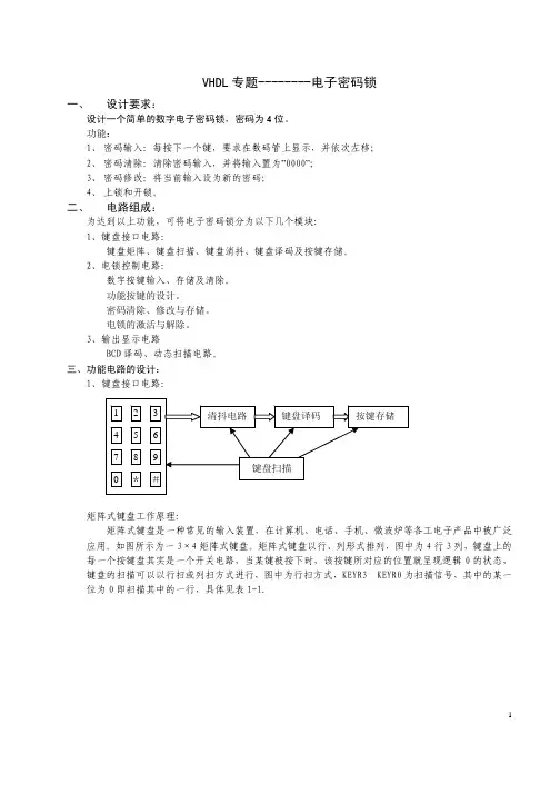
三、功能电路的设计:1、键盘接口电路:矩阵式键盘工作原理:矩阵式键盘是一种常见的输入装置,在计算机、电话、手机、微波炉等各工电子产品中被广泛应用。
如图所示为一3×4矩阵式键盘。
矩阵式键盘以行、列形式排列,图中为4行3列,键盘上的每一个按键盘其实是一个开关电路,当某键被按下时,该按键所对应的位置就呈现逻辑0的状态,键盘的扫描可以以行扫或列扫方式进行,图中为行扫方式,KEYR3—KEYR0为扫描信号,其中的某一位为0即扫描其中的一行,具体见表1-1.12键盘扫描信号KEYR3与第一行相连,KEYR2与第二行相连,依此类推。
很显然,扫描信号的变化顺序为:0111、1011、1101、1110,周而复始。
在扫描的过程中,当有键按下时,对应的键位就为逻辑0状态,从而从KEYC2..0读出的键值相应列为0.具体情况如表1-2所示:若从KEYC2..0读出的值全为1时,表示没有键被按下,则不进行按键的处理。
如果的键被按下,则将KEYC2..0读出的送至键盘译码电路进行译码。
表1-2 键盘扫描与其对应的键值的关系时序产生电路:在一个系统的设计中,往往需要多种时钟信号,最为方便的方法是利用一个自由计数器来产生各种需要的频率。
本电路需要:系统主时钟、消抖取样时钟和动态扫描时钟。
VHDL——按键消抖按键检测需要消抖,一般有硬件和软件两种方式。
硬件就是加去抖动电路,这样从根本上解决按键抖动问题。
除了用专用电路以外,用可编程FPGA或者CPLD设计相应的逻辑和时序电路,对按键信号进行处理,同样可以达到去抖动的目的。
本例中用状态机实现了消抖电路:端口描述:clk输入检测时钟;reset复位信号;din原始按键信号输入;dout去抖动输出信号。
VHDL源码如下:LIBRARY ieee;USE ieee.std_logic_1164.all;USE ieee.std_logic_unsigned.all;ENTITY xiaod ISPORT(clk:IN STD_LOGIC ;reset:IN STD_LOGIC ;din:IN STD_LOGIC ;dout:OUT STD_LOGIC);END ENTITY; ARCHITECTURE RTL OF xiaod IS TYPE state IS( s0,s1,s2,s3); SIGNAL pre_s, next_s:state;BEGINP0:PROCESS( reset, clk ) BEGINif reset = '0' thenpre_s <= s0;elsif rising_edge( clk ) thenpre_s <= next_s;elsenull;end if;END PROCESS P0;P1:PROCESS( pre_s, next_s, din ) BEGINcase pre_s isdout <= '1';if din = '1' then next_s <= s0; elsenext_s <= s1; end if;when s1 => dout <= '1';if din = '1' then next_s <= s0; elsenext_s <= s2; end if;when s2 => dout <= '1';if din = '1' then next_s <= s0; elsenext_s <= s3; end if;dout <= '0';if din = '1' thennext_s <= s0;elsenext_s <= s1;end if;end case;END PROCESS P1;END RTL;多按键去抖动电路VHDL源码,按键个数参数化,每个按键处理调用了上面的模块:LIBRARY ieee;USE ieee.std_logic_1164.all;USE ieee.std_logic_arith.all;USE ieee.std_logic_unsigned.all;ENTITY Nxiaod ISGENERIC( width:positive:= 5 );PORT(clk:IN STD_LOGIC ;reset:IN STD_LOGIC ;din:IN STD_LOGIC_VECTOR( width - 1 DOWNTO 0); dout:OUT STD_LOGIC_VECTOR( width - 1 DOWNTO 0) );END ENTITY;ARCHITECTURE RTL OF Nxiaod IS COMPONENT xiaod ISPORT(clk:IN STD_LOGIC ;reset:IN STD_LOGIC ;din:IN STD_LOGIC ;dout:OUT STD_LOGIC);END COMPONENT;BEGINg1: FOR i IN 0 to width - 1 GENERATEux:xiaod port map( clk => clk, reset => reset, din => din(i), dout =>dout(i)); END GENERATE;END RTL;。
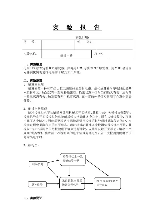
实 验 报 告实验日期: 学 号:姓 名:实验名称:消抖电路总 分:一、实验概述运用LPM 原件定制DFF 触发器,并调用LPM 定制的DFF 触发器,用VHDL 语言的元件例化实现消抖电路并了解其工作原理。
二、实验原理 1、触发器原理触发器是一种可存储1位二进制码的逻辑电路,是构成各种时序电路的最基本逻辑单元。
触发器有一对互补输出端,输出状态不仅与当前输入有关,还与前一输出状态有关。
触发器有两个稳定状态,在一定的外界信号作用下会发生状态翻转。
2、消抖电路原理脉冲按键与电平按键通常采用机械式开关结构,其核心部件为弹性金属簧片。
按键信号在开关拨片与触电接触后经多次弹跳才会稳定,而在按键过程中,可能出现了多个脉冲。
因此需要根据实际情况进行按键消抖处理以提取稳定脉冲,在按键过程中提取稳定的电平状态,通过对抖动脉冲多次检测信号按键电平值,并提取一前一后两个信号按键电平值来进行比较,以此来获取开关状态。
输出一个周期的脉冲时,要求前一次检测到的电平信号为低电平,后一次检测到的电平信号为高电平时。
3、结构图:三、实验设计时钟信号 元件记忆当前的按键信号电平 元件记忆上一次按键信号电平 两次按键的电平进行比较 脉冲信号1、LPM元件定制DFF触发器(1)设置lpm_ff元件选择Installed Plug-Ins→Storage→lpm_ff项。
(2)LPM元件定制步骤,设置输入data为1位,clock为时钟信号,类型为D 型。
(3)添加异步清零和异步置1。
(4)aclr异步清零且高电平有效,aset异步置1且高电平有效,二者无效时,q输出由clock上升沿触发更新为data。
(5)调出其vhd文件添加至消抖电路的工程中。
(6)仿真验证并下载。
功能仿真波形分析参数:end time 为2.0ns,grid size为100ns;信号:alcr 异步清零且高电平有效,二进制;aset异步置1且高电平有效,二进制;二者无效,q(二进制)输出由clock(二进制)上升沿触发更新为data(二进制)。
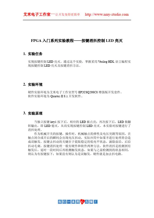
FPGA入门系列实验教程——按键消抖控制LED亮灭1.实验任务实现按键控制LED亮灭。
通过这个实验,掌握采用Verilog HDL语言编程实现按键控制LED亮灭及按键消抖方法。
2.实验环境硬件实验环境为艾米电子工作室型号EP2C8Q208C8增强版开发套件。
软件实验环境为Quartus II8.1开发软件。
3.实验原理当独立按键key1按下后,相应的LED被点亮;再次按下后,LED做翻转输出,即LED熄灭,从而实现按键控制LED亮灭。
本实验对按键进行了消抖处理。
作为机械开关的按键,操作时,机械触点的弹性及电压突跳等原因,在触点闭合或开启的瞬间会出现电压抖动,实际应用中如果不进行处理将会造成误触发。
按键去抖动的关键在于提取稳定的低电平状态,滤除前沿、后沿抖动毛刺。
按键消抖处理一般有硬件和软件两种方法。
软件消抖是检测到有触发后,延时一段时间后再检测触发状态,如果与之前检测到的状态相同,则认为有按键按下;如果没有则认为是误触发。
硬件就是加去抖电路。
4.实验程序module key_debounce(rst_n,clk,key,led);input rst_n;input clk;input key;output led;//通过降采样对key的输入做低通滤波,将其高频分量滤除,得到low_sw值reg[17:0]cnt;always@(posedge clk)if(!rst_n)cnt<=18'd0;elsecnt<=cnt+1'b1;wire sample_pulse=cnt==18'h3ffff;reg low_sw;always@(posedge clk)if(!rst_n)low_sw<=1'b1;else if(sample_pulse)low_sw<=key;//在整个low_sw(active_low)有效过程中取一个控制量作为led的控制信号//本实例中使用low_sw的下降沿reg low_sw_r;//将low_sw信号锁存一个时钟周期,延时不是真的“锁存”always@(posedge clk)low_sw_r<=low_sw;wire led_ctrl=low_sw_r&(!low_sw);reg led;always@(posedge clk or negedge rst_n)if(!rst_n)led<=1'b0;else if(led_ctrl)led<=~led;endmodule5.实验步骤(1)建立新工程项目:打开Quartus II软件,进入集成开发环境,点击File→New project wizard建立一个工程项目key_debounce。
看老外如何实现按键消抖(VHDL )作者:跑丢的孩… 文章来源:跑丢的孩子 点击数:422 更新时间:2012-11-2我们平常所用的按键为机械弹性开关,由于触点的弹性作用,按键在闭合时不会马上稳定的接通,而是有一段时间的抖动,在断开时也不会立即断开。
抖动时间由按键的机械特性所决定,一般为5ms~10ms 。
所以我们在做按键检测时都要加一个消抖的过程。
按键消抖主要有两种方案:一是硬件消抖;二是软件消抖。
下面结合一个例程来看看老外是如何实现软件消抖的。
entity top isPort ( btn_0 : in STD_LOGIC;clk : in STD_LOGIC;led : out STD_LOGIC);end top;architecture Behavioral of top isconstant CNTR_MAX : std_logic_vector(15 downto 0) := (others => '1'); signal btn0_cntr : std_logic_vector(15 downto 0) := (others => '0'); signal led_r : std_logic := '0';signal btn0_reg : std_logic := '0';beginbtn0_debounce_process : process (CLK)beginif (rising_edge(CLK)) thenif (btn0_cntr = CNTR_MAX) thenbtn0_reg <= not(btn0_reg);end if;end if;end process;btn0_counter_process : process (CLK)beginif (rising_edge(CLK)) thenif ((btn0_reg = '1') xor (btn_0 = '1')) thenif (btn0_cntr = CNTR_MAX) thenbtn0_cntr <= (others => '0');elsebtn0_cntr <= btn0_cntr + 1;end if;elsebtn0_cntr <= (others => '0');end if;end if;end process;process(btn0_reg)beginif rising_edge(btn0_reg) thenled_r <= not (led_r);end if;end process;led <= led_r;end Behavioral;一般人的做法是:当第一次检测到按键被按下后,执行一个延时程序,产生一个5ms~10ms的延时程序,然后再一次检测按键的状态,如果仍保持按键闭合状态电平,则认为确实有按键按下。
单片机消除按键抖动的方法
单片机中,当按键被按下时,可能会出现按键抖动的现象,即按下按键后,按键会不断地重复触发,导致程序的不稳定性等问题。
为了消除按键抖动,可以采取以下方法:
1. 软件消抖法:在程序中通过延时、多次采样等方法,对按键
进行去抖处理。
但这种方法需要占用一定的CPU资源,容易影响程序的稳定性和响应速度。
2. 硬件消抖法:通过外部电路对按键进行去抖处理,如添加 RC 滤波器、加电容等组合电路,可稳定按键的电平信号,避免按键的震动和干扰。
3. 系统延时法:在按键按下后,延时一段时间再读取按键的状态,可消除按键的抖动。
但这种方法需要根据实际情况设置合适的延时时间,否则会影响系统的响应速度。
4. 确认法:在按键按下后,通过程序对按键的状态进行多次确认,只有当确认多次读取的状态一致时,才认为按键的状态是有效的。
这种方法需要设置合适的确认次数和时间,才能达到较好的去抖效果。
总之,消除按键抖动是单片机程序开发中的一个重要问题,需要根据实际情况选择合适的去抖方案,保证程序的稳定性和可靠性。
- 1 -。
目录摘要 (1)第一章 EDA技术简介 (2)第二章按键去抖设计要求 (3)第三章按键去抖分析 (3)第四章按键去抖设计方案 (4)第五章按键去抖模块 (5)5.1 去抖动电路模块 (5)5.2 去抖动电路模块程序 (5)5.3 按键扫描模块 (6)5.4 按键扫描程序 (7)第六章按键去抖的顶层原理图设计 (8)6.1 顶层原理图的源文件 (8)6.2顶层原理图的时序仿真图 (9)第七章学习心得 (10)课程设计评分表............................................................................................... 错误!未定义书签。
摘要为了解决FPGA/ CPLD 系统的按键抖动问题, 用VH DL 语言有限状态机的方法, 在S0 状态下检测到有按键操作则转入延时状态S1 ,延时结束后, 用状态S2 , S3 , S4 对按键进行连续三次取样,如果三次取样均为低电平, 则转入状态S5并输出按键确认信号,否则, 返回状态S0。
电路经仿真分析, 并下载到, EPM7128ATC100 芯片进行了验证, 能够确保每次按键操作,产生一次按键确认, 有很好的按键消抖效果, 性能稳定。
主要创新点是用VHDL语言有限状态机设计按键的消抖。
关键词:按键消抖; 电路仿真; VH DL;状态机第一章 EDA技术简介随着电子技术和计算机技术的飞速发展,电子线路的设计工作也日益显得重要。
经过人工设计、制作实验板、调试再修改的多次循环才定型的传统产品设计方法必然被计算机辅助设计所取代,因为这种费时费力又费资源的设计调试方法既增加了产品开发的成本,又受到实验工作场地及仪器设备的限制。
为了克服上述困难,加拿大Interactive Image Technologies公司推出的基于Windows 95/98/NT操作系统的EDA软件(Electronics Workbench“电子工作台”,EWB)。
本程序利用VHDL实现功能:按下键开始计时,再次按下停止计时,再次按下清零,再次按下开始计时4位数码管显示,最大99.99秒。
程序分为分频模块,按键消抖模块/数码管显示转换模块和top模块--通用偶数分频器—输入时钟和复位信号,输出分频后的时钟library ieee;use ieee.std_logic_1164.all;use ieee.std_logic_arith.all;use ieee.std_logic_unsigned.all;entity gen_div isgeneric(div_param:integer:=1);--分频因子,分频为2*div_param,默认2分频port(clk:instd_logic;--输入时钟bclk:outstd_logic;--分频输出resetb:instd_logic--复位信号);end gen_div;architecture behave of gen_div issignal tmp:std_logic;--输出暂存寄存器signal cnt:integer range 0 to div_param:=0;--计数寄存器begin------------------------------process(clk,resetb)beginif resetb='1' then --reset有效时,bclk始终是0 cnt<=0;tmp<='0';elsifrising_edge(clk) thencnt<=cnt+1;if cnt=div_param-1 thentmp<=not tmp;--取反信号cnt<=0;end if;end if;end process;bclk<=tmp;--输出--------------------------------end behave;--按键消抖模块--输入时钟和复位信号,按键信号,输出按键标识--确定按下之后输出一个值library ieee;use ieee.std_logic_1164.all;use ieee.std_logic_arith.all;use ieee.std_logic_unsigned.all;entity sig_key isport( clkin,resetin:instd_logic;--时钟,复位信号输入key:instd_logic;--键输入key_out:outstd_logic—输出按键标识);end sig_key;architecture behave of sig_key iscomponent gen_div is--分频元件调用声明generic(div_param:integer:=2);--默认是4分频port(clk:instd_logic;bclk:outstd_logic;resetb:instd_logic);----type key_state is (check_down,off_twitter,re_check_down);signal sk_state_key0:key_state:=check_down;--定义按键3状态,分别是等待按下确定按下signal clk_1k:std_logic;--1k时钟,T=1ms—用于延时begingen_1k: --分频产生1k脉冲gen_div generic map(24000)--48000分频的,产生1k脉冲port map--分频元件例化(clk=>clkin,resetb=>not resetin,bclk=>clk_1k);---check_key0_state:process(clk_1k,resetin,key)variable cnt:integer range 0 to 63:=0;beginif resetin='0' thenkey_out<='0';sk_state_key0<=check_down;elseif rising_edge(clk_1k) thencase sk_state_key0 iswhen check_down=>if key='1' then--=0位按下,1位松开sk_state_key0<=check_down;key_out<='0';--松开了,输出0elsif key='0' then--有键按下,准备消抖sk_state_key0<=off_twitter;cnt:=0;end if;when off_twitter=>--延时10ms,消抖cnt:=cnt+1;if cnt>=10 thensk_state_key0<=re_check_down;cnt:=0;end if;when re_check_down=>if key='1' thensk_state_key0<=check_down;--重新检测elsif key='0' then--确实有键按下key_out<= '1'; --输出1sk_state_key0<=check_down;--进入下一次检测end if;when others=>null;end case;end if;end if;end process;end behave;数码管显示转换模块—输入时钟复位信号和数字,输出段码--把输入的整型转变为对应显示段码library ieee;use ieee.std_logic_1164.all;use ieee.std_logic_arith.all;use ieee.std_logic_unsigned.all;entity led_change isport( clkin,resetin:instd_logic;--时钟,复位信号输入data_in:in integer range 0 to 21;--输入整型data_out:outstd_logic_vector(7 downto 0)--数码管段码输出);end led_change;architecture behave of led_change isbeginprocess(clkin,resetin,data_in)beginif resetin='1' thendata_out<=X"FF";---复位后全灭elseif rising_edge(clkin) thencase data_in iswhen 0=>data_out<=X"03";when 1=>data_out<=X"9F";when 2=>data_out<=X"25";when 3=>data_out<=X"0d";when 4=>data_out<=X"99";when 5=>data_out<=X"49";when 6=>data_out<=X"41";when 7=>data_out<=X"1F";when 8=>data_out<=X"01";when 9=>data_out<=X"09";when 10=>data_out<=X"02";--0带点,用于区分秒和毫秒when 11=>data_out<=X"9E";--1带点,下同when 12=>data_out<=X"24";when 13=>data_out<=X"0C";when 14=>data_out<=X"98";when 15=>data_out<=X"48";when 16=>data_out<=X"40";when 17=>data_out<=X"1E";when 18=>data_out<=X"00";when 19=>data_out<=X"08";when others=>data_out<=X"FF";end case;end if;end if;end process; end behave;top模块,输入总时钟,总复位,按键,输出段码和位码--秒计数器,按下开始计时,按下停止,按下清零,按下开始library ieee;use ieee.std_logic_1164.all;use ieee.std_logic_arith.all;use ieee.std_logic_unsigned.all;entity stopwatch isport(clk_init,reset_init:instd_logic;sw:instd_logic;led:outstd_logic;--指示状态data:outstd_logic_vector(7 downto 0);--数码管段码输出com:outstd_logic_vector(3 downto 0)--位码输出);end stopwatch;architecture behave of stopwatch is---申明分频模块gen_divcomponent gen_div isgeneric(div_param:integer:=1);--分频因子,分频为2*div_param,默认2分频port(clk:instd_logic;--输入时钟bclk:outstd_logic;--分频输出resetb:instd_logic--复位信号);end component;--申明数码管数据转换模块led_changecomponent led_change is--段码转换调用port(clkin,resetin:instd_logic;--时钟,复位信号输入data_in:in integer range 0 to 21;--输入整型data_out:outstd_logic_vector(7 downto 0)--数码管段码输出);end component;--申明按键消抖模块sig_keycomponent sig_key isport(clkin,resetin:instd_logic;--时钟,复位信号输入key:instd_logic;--键输入key_out:outstd_logic);end component;--定义信号----承接转化之前的数字signal data_1_tmp: integer range 0 to 21;--段码个位signal data_10_tmp: integer range 0 to 21;--段码十位signal data_100_tmp: integer range 0 to 21;--段码百位signal data_1000_tmp: integer range 0 to 21;--段码千位---承接经转化后的段码signal data_1:std_logic_vector(7 downto 0);--段码个位signal data_10:std_logic_vector(7 downto 0);--段码十位signal data_100:std_logic_vector(7 downto 0);--段码百位signal data_1000:std_logic_vector(7 downto 0);--段码千位signal clk_sm:std_logic;--50k扫描周期signal key_out_init:std_logic;--承接按键消抖模块传出来的按键信号signal cnt_50k:std_logic_vector(1 downto 0);--对clk_sm计数,产生4种状态,对应位码type sw_state_wich is (sw_1,sw_2,sw_3);--按钮状态,1清零等待启动,2计时中,3停止signal sw_state:sw_state_wich:=sw_1;begin--例化gen_100k: --分频产生50k脉冲gen_div generic map(480)—48M晶振,960分频,得到50k时钟port map--分频元件例化(clk=>clk_init,resetb=> not reset_init,bclk=>clk_sm);gen_data_1:--个位段码转换led_change port map(clkin=>clk_init,resetin=>not reset_init,data_in=>data_1_tmp,data_out=>data_1);gen_data_10:--十位段码转换led_change port map(clkin=>clk_init,resetin=>not reset_init,data_in=>data_10_tmp,data_out=>data_10);gen_data_100:--百位段码转换led_change port map(clkin=>clk_init,resetin=>not reset_init,data_in=>data_100_tmp,data_out=>data_100);gen_data_1000:--千位段码转换led_change port map(clkin=>clk_init,resetin=>not reset_init,data_in=>data_1000_tmp,data_out=>data_1000);key_sig:--调用按键消抖程序sig_key port map(clk_init,reset_init,sw,key_out_init);gen_cnt_50k:--cnt_50k循环计数,四个状态的循环周期是20us*4=80us,即为扫描周期process(clk_sm,reset_init,data_1000,data_100,data_10,data_1) beginif reset_init='0' thencnt_50k<="00";elseif rising_edge(clk_sm) thencnt_50k<=cnt_50k+'1';end if;end if;end process;Display:--根据上面的计数将转换后的段码送给对应的位process(cnt_50k,data_1,data_10,data_100,data_1000)begincase cnt_50k is--循环扫描when "00"=> com<="0111";data<=data_1000;--千位when "01"=> com<="1011";data<=data_100;--百位when "10"=> com<="1101";data<=data_10;--十位when "11"=> com<="1110";data<=data_1;--个位when others=> com<="1111";--全灭end case;end process;process(key_out_init,clk_sm)variable cnt_clk_1k :integer range 0 to 3000000:=0;--用于计时variable key_flog:std_logic:='0';--用于判断按键是否松开,0表示松开beginif rising_edge(clk_sm) thencase sw_state iswhen sw_1 =>if key_out_init='0' then –松开,置1key_flog:='1';end if;if key_out_init='1' and key_flog='1' then—按下,且之前是松开转到状态2开始计时,按下后flog置0sw_state<= sw_2;key_flog:='0';end if;when sw_2 =>if key_out_init='0' then--松开健开始计时,且置1key_flog:='1';cnt_clk_1k:=cnt_clk_1k+1;data_1_tmp <= ( cnt_clk_1k /50 / 10 ) rem 10;data_10_tmp <= ( cnt_clk_1k /50 / 100 ) rem 10;data_100_tmp <= ( cnt_clk_1k /50 / 1000 ) rem 10+10;data_1000_tmp <= ( cnt_clk_1k /50 / 10000 ) rem 10;end if;if key_flog='1' then –置1表示已经松开if key_out_init='1' then –再次按下sw_state<= sw_3;key_flog:='0';end if;end if;when sw_3 =>if key_out_init='0' thenkey_flog:='1';end if;if key_flog='1' thenif key_out_init='1' thensw_state<= sw_1;key_flog:='0';cnt_clk_1k:=0;data_1_tmp <=0;--清零data_10_tmp <=0;data_100_tmp <=0;data_1000_tmp <=0;end if;end if;when others =>sw_state<= sw_1;end case;end if;end process;end behave;--top程序应该有复位信号,本除没有加。
在使用单片机搭建有人机交互的系统时需要用到键盘,因为单片机工作时间都是纳秒与毫秒级别,但是我们人体的反应时间最少要0.2秒,之间差距很大,现实过程中也会不小心碰到按键,正常的按下按键应该是持续数十秒的稳定。
一、按键电路常用的非编码键盘,每个在使用单片机搭建有人机交互的系统时需要用到键盘,因为单片机工作时间都是纳秒与毫秒级别,但是我们人体的反应时间最少要0.2秒,之间差距很大,现实过程中也会不小心碰到按键,正常的按下按键应该是持续数十秒的稳定。
一、按键电路常用的非编码键盘,每个键都是一个常开开关电路。
计数器输入脉冲最好不要直接接普通的按键开关,因为记数器的记数速度非常快,按键、触点等接触时会有多次接通和断开的现象。
我们感觉不到,可是记数器却都记录了下来。
例如,虽然只按了1下,记数器可能记了3下。
因此,使用按键的记数电路都会增加单稳态电路避免记数错误。
二、按键消抖通常的按键所用开关为机械弹性开关,当机械触点断开、闭合时,电压信号小型如下图。
由于机械触点的弹性作用,一个按键开关在闭合时不会马上稳定地接通,在断开时也不会一下子断开。
因而在闭合与断开的瞬间均伴随有一连串的抖动,如下图。
抖动时间的长短由按键的机械特性决定,一般为5ms~10ms。
这是一个很重要的时间参数,在很多场合都要用到。
按键稳定闭合时间的长短则是由操作人员的按键动作决定的,一般为零点几秒至数秒。
键抖动会引起一次按键被误读多次。
为确保CPU对键的一次闭合仅作一次处理,必须去除键抖动。
在键闭合稳定时读取键的状态,并且必须判别到键释放稳定后再作处理。
按键的抖动,可用硬件或软件两种方法。
三、硬件消抖在键数较少时可用硬件方法消除键抖动。
下图所示的RS触发器为常用的硬件去抖。
消抖电路如下图中两个“与非”门构成一个RS触发器。
当按键未按下时,输出为1;当键按下时,输出为0。
此时即使用按键的机械性能,使按键因弹性抖动而产生瞬时断开(抖动跳开B),中要按键不返回原始状态A,双稳态电路的状态不改变,输出保持为0,不会产生抖动的波形。
单片机按键去抖动程序设计思路
1.去抖动原理:按键在按下和松开的瞬间会产生震动,导致按键信号在短时间内出现多次转换,给程序带来困扰。
为了解决这个问题,需要对按键信号进行去抖动处理,即在按键按下和松开时,只记录一次按键状态变化。
2.软件去抖动方法:软件去抖动方法主要通过软件延时来判断按键信号是否稳定。
具体来说,可以通过以下步骤实现软件去抖动:-初始化按键引脚为输入模式,并使能内部上拉电阻;
-设定一个延时时间阈值t,用于判断按键是否稳定;
-读取按键引脚的电平,如果为低电平,说明按键按下;
-进入一个循环,每次循环读取一次按键引脚的电平,并与前一次读取的电平进行比较;
-如果连续读取到的电平与前一次相同,说明按键信号稳定;
-如果连续读取到的电平与前一次不同,则说明按键信号还在抖动,继续读取直到连续读取到的电平与前一次相同;
-当稳定的电平持续时间超过延时时间阈值t时,认为按键信号已稳定,可以进行相应的处理。
3. 硬件去抖动方法:硬件去抖动方法主要通过电路设计来实现。
常见的硬件去抖动电路包括RC滤波电路和Schmitt触发器电路。
其中,RC 滤波电路利用电容和电阻的特性,对按键信号进行平滑处理;Schmitt触发器电路则通过正反馈的方式,将不稳定的信号转换为稳定的信号。
这两种方法可以根据实际需求选择。
总结:
按键去抖动程序设计可以通过软件去抖动和硬件去抖动两种方式实现。
软件去抖动主要通过软件延时判断按键信号是否稳定,而硬件去抖动则通
过电路设计实现。
根据具体的应用场景和需求,可以选择适合的方法来设
计按键去抖动程序。
1.vhdl按键消抖程序一:延时性消抖在本例子中,input是按键的输入,output是消抖之后的按键输出是clk经历8个上升沿之后就让output输出一个CLK周期的高电平library ieee;use ieee.std_logic_1164.all;entity PWlock isport(clk:in std_logic;input:in std_logic;output:out std_logic);end PWlock;architecture one of PWlock issignal a:std_logic;signal count:integer range 0 to 9;beginprocess(clk)beginif input=‘0’ thencount<=0;elsif (clk‘event and clk=’1‘)thenif count=9 thencount<=count;elsecount<=count+1;end if;end if; -if count=8 thena<=’0‘;elsea<=’1‘;end if;end process;output<=a;end one;2.vhdl按键消抖程序二一般按键延时在20ms左右,根据时钟频率决定你的计数范围。
程序非常简单,但经常用到,对于FPGA初学者要好好学习这部分。
library ieee;use ieee.std_logic_1164.all;use ieee.std_logic_unsigned.all;entity reseter isport(clk,reset_in:in std_logic; --按键按下时为0reset_out:out std_logic:=‘0’);end reseter;architecture behav of reseter isbeginPROCESS(clk,reset_in)VARIABLE COUNT1 :INTEGER RANGE 0 TO 100000;BEGINIF reset_in=‘0’ THENIF RISING_EDGE(clk)THENIF COUNT1<10000 THEN COUNT1:=COUNT1+1;ELSE COUNT1:=COUNT1; END IF;IF COUNT1<=9999 THEN reset_out<=‘1’;ELSE reset_out<=‘0’; END IF;END IF;ELSE COUNT1:=0;reset_out<=‘1’;END IF;END PROCESS ;end behav;3.vhdl按键消抖程序三:计数器型消抖电路(一)计数器型消抖电路是设置一个模值为(N+1)的控制计数器,clk在上升沿时,如果按键开关key_in=‘1’,计数器加1,key_in=‘0’时,计数器清零。
当计数器值为2时,key_out输出才为1,其他值为0时。
计数器值为N时处于保持状态。
因此按键key_in持续时间大于N 个clk时钟周期时,计数器输出一个单脉冲,否则没有脉冲输出。
如果按键开关抖动产生的毛刺宽度小于N个时钟周期,因而毛刺作用不可能使计数器有输出,防抖动目的得以实现。
clk的时钟周期与N的值可以根据按键抖动时间由设计者自行设定。
主要程序结构如下:if(clk’event and clk=’1’)thenif(key_in=’1’)thenif count=N thencount<=count;else count<=count+1;end if;end if;else count<=0;end if;4.vhdl按键消抖程序四:计数器型消抖电路(二)计数器型消抖电路(二)是控制计数器工作一个循环周期(N+1个状态),且仅在计数器为0时输出为“1”。
电路设计了连锁控制设施。
在计数器处于状态0时,此时若有按键操作,则计数器进入状态1,同时输出单脉冲(其宽度等于时钟周期)。
计数器处于其他状态,都没有单脉冲输出。
计数器处于状态N时,控制en=‘0’,导致计数器退出状态N,进入状态0。
计数器能否保持状态0,取决于人工按键操作,若按键key_in=‘1’,控制en=‘1’(计数器能正常工作),key_in=‘0’,计数器状态保持。
显见计数器处于状态0,人工不按键,则计数器保持状态0。
主要程序结构如下:if count=N thencount<=0;else count<=count+1;end if;if count=0 thenkey_out<=’0’;end if;end ifend process;B:process(clk)beginif(clk’event and clk=’1’)thenif count<N thenif key_in=’1’ thenen<=’1’;else en<=en;end if;end if;end process;5.vhdl按键消抖程序五:D触发器型消抖电路D触发器型消抖电路设计了三个D触发器与一个三输入与门。
三个D触发器串行连接,其Q输出端分别与三输入与门的输入端连接.主要程序结构如下:key_out<=d1 or d2 or d3;process(clock)beginif(clk’event and clk=’1’)thend1<=key_in; d2<=d1; d3<=d2;end if;end process;补充:改进型D触发器(正负双输出端,本次实验被多次引用)library ieee;use ieee.std_logic_1164.all;use ieee.std_logic_arith.all;use ieee.std_logic_unsigned.all;entity qdd isport(key,clk:in std_logic;up:out std_logic);end qdd;architecture a of qdd issignal q0,q1:std_logic;beginprocess(clk)beginif (clk'event and clk='1')thenq0<=key;q1<=q0;end if;end process;up<=(q1 and (not q0));end a;6.vhdl按键消抖程序六:状态机型消抖电路状态机型消抖电路采用有限状态机的设计方法来描述与实现,状态机有S0,S1,S2三种状态,在S0状态下key_out输出为低电平,并以clk时钟信号的频率采样按键输入信号,如果key_in=‘0’,则保持在S0状态,并继续采样按键输入信号的状态,如果key_in=‘1’,则转入S1状态;在S1状态下key_out输出仍为低电平,继续采样按键输入信号的状态,如果key_in=‘1’,则转入S2状态,如果key_in=‘0’则转入S0状态;在S2状态下继续采样按键输入信号的状态,如果key_in=‘1’,则保持在S2状态,key_out输出正脉冲,如果key_in=‘0’,则转入S0状态,key_out输出低电平。
主要程序结构如下:if clk’event and clk=’1’ thencase sta iswhen s0=>key_out<=’0’;if key_in=’1’thens<=s1;else s<=s0;end if;when s2=>if key_in=’1’thenkey_out<=’1’;s<=s2;else s<=s0;end if;when s2=>if key_in=’1’ thenkey_out<=’1’;s<=s2;elsekey_out<=’0’;s<=s0;end if;end case;end if;7.vhdl按键消抖程序七end程序中所用的方法是不断检测按键值。
每当Count[17]上升沿到来,就进行检测输入信号。
其中dout1,dout2,dout3分别为当前、上个Count[17]上升沿、上上个Count [17]上升沿输入数值。
正常情况下为1,假如连续三次为0,三个信号作或运算,使得key_done信号为0,出现下降沿,这样就认为是有按键。
assign key_done = (dout1 | dout2 | dout3); //按键消抖输出always @(posedge count[17])begindout1 <= key_in;dout2 <= dout1;dout3 <= dout2;endalways @(negedge key_done[0])beginkeyen = ~keyen;。