ASTM D1002-10拉伸剪切强度测试标准中文版
- 格式:pdf
- 大小:13.55 MB
- 文档页数:8
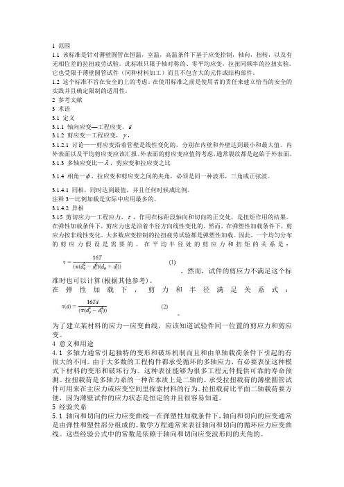
1 范围1.1 该标准是针对薄壁圆管在恒温,室温,高温条件下基于应变控制,轴向,扭转,以及有无相位差的拉扭疲劳试验。
此标准只限于轴对称的、零平均应变,拉扭同频率的拉扭实验。
它也受限于薄壁圆管试件(同种材料加工)而且不包含大的元件或结构部件。
1.2 这个标准不旨在安全的上的考虑。
在使用标准之前是使用者的责任来建立恰当的安全的实践并且确定限制的适用性。
2 参考文献3 术语3.1 定义3.1.1 轴向应变—工程应变,ε3.1.2 剪应变—工程应变,γ,3.1.2.1 讨论——剪应变沿着管壁是线性变化的,分别在内壁和外壁达到最小和最大值。
内外表面以及平均剪应变应该汇报。
外表面的剪应变应值得考虑,通常裂纹都是起始于外表面。
3.1.3 多轴应变比—λ,剪应变和拉应变之比3.1.4 相角—φ,拉应变和剪应变之间的夹角,必须是同一种波形,三角或正弦波。
3.1.4.1 同相,同时达到最值,并且任何时候成比例。
注释3—比例加载是实际中应用最多的。
3.1.4.2 异相3.15 剪切应力—工程应力,τ,作用在标距段轴向和切向的正交处,是扭矩作用的结果。
在弹性加载条件下,剪应力也是沿着半径方向线性变化的。
然而,在弹塑性加载条件下,剪应力按非线性变化。
大多数应变控制的拉扭疲劳试验都是弹塑性加载。
因此,一个均匀分布的剪应力假设是需要的。
在平均半径处的剪应力和扭矩的关系是:,然而,试件的剪应力不满足这个标准时也可以计算(根据其他参考)。
在弹性加载下,剪力和半径满足关系式:。
为了建立某材料的应力—应变曲线,应该知道试验件同一位置的剪应力和剪应变。
4 意义和用途4.1 多轴力通常引起独特的变形和破坏机制而且和由单轴载荷条件下引起的有很大的不同。
由于大多数的工程构件都承受循环的多轴应力,有必要表征这种模式下材料的变形和破坏行为。
这种表征能够为很多工程元件提供可靠的寿命预测。
拉扭载荷是多轴力系的一种在本质上是二轴的。
承受拉扭载荷的薄壁圆管试件可用来在主应力或应变空间里探索材料的行为。

B36/B36M Specification for Brass Plate,Sheet,Strip,and Rolled Bar3B152Specification for Copper Sheet,Strip,Plate,and Rolled Bar3B209Specification for Aluminum and Aluminum-Alloy Sheet and Plate4B265Specification for Titanium and Titanium Alloy Strip, Sheet,and Plate5D907Terminology of Adhesives6D4896Guide for Use of Adhesive-Bonded Single Lap-Joint Specimen Test Results6E4Practices for Force Verification of Testing Machines7 3.Terminology3.1Definitions—Many terms in this test method are defined in Terminology D907.4.Significance and Use4.1This test method is primarily comparative.However,it does have application as a discriminator in determining varia-tions in adherend surface preparation parameters and adhesive environmental durability.The test method has found applica-tions in controlling surface preparations,primer,and adhesive systems for determining strength properties of tested systems.4.2The misuse of strength values obtained from this test method as design-allowable stress values for structural joints could lead to product failure,property damage,and human injury.The apparent shear strength of an adhesive obtained from a given small single-lap specimen may differ from that obtained from a joint made with different adherends or by a different bonding process.The normal variation of temperature and moisture in the service environment causes the adherends and the adhesive to swell or shrink.The adherends and adhesive are likely to have different thermal and moisture coefficients of expansion.4.3Even in small specimens,short-term environmental changes may induce internal stresses or chemical changes in the adhesive that permanently affect the apparent strength and other mechanical properties of the adhesive.The problem of predicting joint behavior in a changing environment is even more difficult if a different type of adherend is used in a larger structural joint than was used in the small specimen.4.4The apparent shear strength measured with a single-lap specimen is not suitable for determining design-allowable stresses for designing structural joints that differ in any manner from the joints tested without thorough analysis and under-standing of the joint and adhesive behaviors.4.5Single-lap tests may be used for comparing and select-ing adhesives or bonding processes for susceptibility to fatigue and environmental changes,but such comparisons must be made with great caution since different adhesives may respond differently in different joints.See Guide D4896for further discussion of the concepts relative to interpretation of adhesive-bonded single-lap-joints.5.Apparatus5.1The testing machine shall conform to the requirements of Practices E4.The testing machine shall be so selected that the breaking load of the specimens falls between15and85 percent of the full-scale capacity.The machine shall be capable of maintaining a rate of loading of80to100kg/cm2(1200to 1400psi)/min,or,if the rate is dependent on crosshead motion, the machine should be set to approach this rate of loading, approximately0.05in./min.It shall be provided with a suitable pair of self-aligning grips to hold the specimen.It is recom-mended that the jaws of these grips shall engage the outer25 mm(1in.)of each end of the test specimenfirmly.5.2The grips and attachments shall be so constructed that they will move into alignment with the test specimen as soon as the load is applied,so that the long axis of the test specimen will coincide with the direction of the applied pull through the center line of the grip assembly.5.3The length of overlap of the specimen may be varied where necessary.The length of the specimen in the jaws, however,must not be varied.The distance from the end of the lap to the end of the jaws should be63mm(21⁄2in.)in all tests.6.Test Specimens6.1Test specimens shall conform to the form and dimen-sions shown in Fig.1.These shall be cut from test panels prepared as prescribed in Section7.The recommended thick-ness of the sheets is1.6260.125mm(0.06460.005in.).The recommended length ofoverlap for most metals of1.62mm(0.064in.)in thickness is12.760.25mm(0.560.01in.).6.2Since it is undesirable to exceed the yield point of themetal in tension during test,the permissible length of overlapin the specimen will vary with the thickness and type of metal,and on the general level of strength of the adhesive beinginvestigated.The maximum permissible length may be com-puted from the following relationship:L5Fty t/t(1)where:L=length of overlap,in.,t=thickness of metal,in.,Fty=yield point of metal(or the stress at proportionallimit),psi,andt=150percent of the estimated average shear strengthin adhesive bond,psi.6.3A variation in thickness of the metal,and the length ofoverlap,will likely influence the test values and make directcomparison of data questionable.For this reason,in compara-tive or specification tests,the thickness should preferably be1.6260.125mm(0.06460.005in.)and the length of overlap3Annual Book of ASTM Standards,V ol02.01.4Annual Book of ASTM Standards,V ol02.02.5Annual Book of ASTM Standards,V ol02.04.6Annual Book of ASTM Standards,V ol15.06.7Annual Book of ASTM Standards,V ol03.01.FIG.1Form and Dimensions of Test Specimenshould preferably be12.760.25mm(0.560.01in.),or not in excess of the value computed in6.2.For development tests values could be different,but should then be constant.6.4The following grades of metal are recommended for the test specimens:Metal ASTM DesignationBrass B36,C26800(Alloy8)Copper B152,C11000Aluminum B209,Alloy2024,T3temperSteel A109,Grade2Corrosion-resisting steel A167,Type302Titanium B2656.5At least30specimens shall be tested,representing at least four different joints.However,if statistical analysis of data and variance is employed,it should be possible to reduce this number.7.Preparation of Test Joints7.1It is recommended that test specimens be made up in multiples of at leastfive specimens,and then cut into indi-vidual test specimens(Note1),Fig.2and Fig.3.Cut sheets of the metals prescribed in6.1and6.4to suitable size.All edges of the metal panels and specimens which will be within(or which will bound)the lap joints shall be machined true (without burrs or bevels and at right angles to faces)and smooth(rms160max)before the panels are surface-treated and bonded.Clean and dry the sheets carefully,according to the procedure prescribed by the manufacturer of the adhesive, and assemble in pairs.Prepare and apply the adhesive accord-ing to the recommendations of the manufacturer of the adhe-sive.Apply the adhesive to a sufficient length in the areaacross FIG.2Standard TestPanelthe end of one or both metal sheets so that the adhesive willcover a space approximately 6mm (1⁄4in.)longer than theoverlap as selected in Section 6.Assemble the sheets so thatthey will be held rigidly so that the length of the overlap willbe controlled,as indicated in Section 6,within 0.25mm(60.01in.),and the adhesive allowed to cure as prescribed bythe manufacturer of the adhesive.N OTE 1—Bonding specimens in multiple panels is believed to givemore representative specimens.However,individual specimens may beprepared if agreeable to the supplier or the purchaser of the adhesive.8.Preparation of Test Specimens8.1Cut the test specimens,as shown in Fig.1,from thepanels,Figs.2and 3.Perform the cutting operation so as toavoid overheating or mechanical damage to the joints (Note 2).For final preparation trim panel area according to Fig. 2.Measure the width of the specimen and the length of theoverlap to the nearest 0.25mm (0.01in.)to determine the sheararea.N OTE 2—A five-tooth,typesetter’s circular saw has been found suitablefor such purposes.9.Procedure9.1Test the specimens,prepared as prescribed in Section 8,as soon after preparation as possible.The manufacturer of the adhesive may,however,prescribe a definite period of condi-tioning under specific conditions before testing.9.2Place the specimens in the grips of the testing machine so that the outer 25mm (1in.)of each end are in contact with the jaws (see 5.3)and so that the long axis of the test specimen coincides with the direction of applied pull through the center line of the grip assembly.Apply the loading immediately to the specimen at the rate of 80to 100kg/cm 2(1200to 1400psi)of the shear area per min.Continue the load to failure.This rate of loading will be approximated by a free crosshead speed of 1.3mm (0.05in.)/min.10.Calculations 10.1Record the load at failure and the nature and amount of this failure (cohesion in adhesive or metal,or adhesion)for each specimen.Express all failing loads in kilograms per square centimeter (pounds per square inch)of shear area,calculated to the nearest 0.06cm 2(0.01in.2).11.Report 11.1Report the following:11.1.1Complete identification of the adhesive tested,in-cluding type,source,date manufactured,manufacturers’code numbers,form,etc.,11.1.2Complete identification of the metal used,its thick-ness,and the method of cleaning and preparing its surfaces prior to bonding,11.1.3Application andbonding conditions used in prepar-ing specimens,11.1.4Average thickness of adhesive layer after formation of the joint within 0.001in.(0.025mm).The method of obtaining the thickness of the adhesive layer shall be described including procedure,location of measurements,and range of measurements.11.1.5Length of overlap used,11.1.6Conditioning procedure used for specimens prior to testing,11.1.7Number of specimens tested,11.1.8Number of joints represented and type of joint if other than single overlap,11.1.9Maximum,minimum,and average values for the failing load,and 11.1.10The nature of the failure,including the average estimated percentages of failure in the cohesion of the adhe-sive,contact failure,and adhesion to the metal.12.Precision and Bias 12.1The precision and bias statement for this test method has not been determined yet.Archival and round-robin infor-mation is being reviewed,and the results are expected by September 2004.13.Keywords 13.1adhesives;metal-to-metal;shear strength;single-lap joint;tension loadingFIG.3Optional Panel for Acceptance Tests OnlyThe American Society for Testing and Materials takes no position respecting the validity of any patent rights asserted in connection with any item mentioned in this ers of this standard are expressly advised that determination of the validity of any such patent rights,and the risk of infringement of such rights,are entirely their own responsibility.This standard is subject to revision at any time by the responsible technical committee and must be reviewed everyfive years and if not revised,either reapproved or withdrawn.Your comments are invited either for revision of this standard or for additional standards and should be addressed to ASTM Headquarters.Your comments will receive careful consideration at a meeting of the responsible technical committee,which you may attend.If you feel that your comments have not received a fair hearing you should make your views known to the ASTM Committee on Standards,at the address shown below.This standard is copyrighted by ASTM,100Barr Harbor Drive,PO Box C700,West Conshohocken,PA19428-2959,United States. Individual reprints(single or multiple copies)of this standard may be obtained by contacting ASTM at the above address or at 610-832-9585(phone),610-832-9555(fax),or service@(e-mail);or through the ASTM website().。
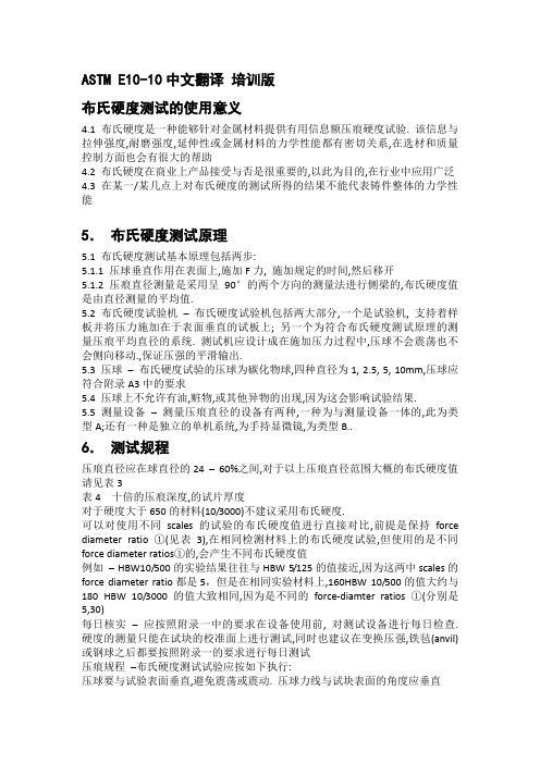
ASTM E10-10中文翻译培训版布氏硬度测试的使用意义4.1 布氏硬度是一种能够针对金属材料提供有用信息额压痕硬度试验. 该信息与拉伸强度,耐磨强度,延伸性或金属材料的力学性能都有密切关系,在选材和质量控制方面也会有很大的帮助4.2 布氏硬度在商业上产品接受与否是很重要的,以此为目的,在行业中应用广泛4.3 在某一/某几点上对布氏硬度的测试所得的结果不能代表铸件整体的力学性能5.布氏硬度测试原理5.1 布氏硬度测试基本原理包括两步:5.1.1 压球垂直作用在表面上,施加F力, 施加规定的时间,然后移开5.1.2 压痕直径测量是采用呈90°的两个方向的测量法进行侧梁的,布氏硬度值是由直径测量的平均值.5.2 布氏硬度试验机–布氏硬度试验机包括两大部分,一个是试验机, 支持着样板并将压力施加在于表面垂直的试板上; 另一个为符合布氏硬度测试原理的测量压痕平均直径的系统. 测试机应设计成在施加压力过程中,压球不会震荡也不会侧向移动.,保证压强的平滑输出.5.3 压球–布氏硬度试验的压球为碳化物球,四种直径为1, 2.5, 5, 10mm,压球应符合附录A3中的要求5.4 压球上不允许有油,赃物,或其他异物的出现,因为这会影响试验结果.5.5 测量设备–测量压痕直径的设备有两种,一种为与测量设备一体的,此为类型A;还有一种是独立的单机系统,为手持显微镜,为类型B..6.测试规程压痕直径应在球直径的24 –60%之间,对于以上压痕直径范围大概的布氏硬度值请见表3表4 十倍的压痕深度,的试片厚度对于硬度大于650的材料(10/3000)不建议采用布氏硬度.可以对使用不同scales的试验的布氏硬度值进行直接对比,前提是保持force diameter ratio ①(见表3),在相同检测材料上的布氏硬度试验,但使用的是不同force diameter ratios①的,会产生不同布氏硬度值例如– HBW10/500的实验结果往往与HBW 5/125的值接近,因为这两中scales的force diameter ratio都是5,但是在相同实验材料上,160HBW 10/500的值大约与180 HBW 10/3000的值大致相同,因为是不同的force-diamter ratios ①(分别是5,30)每日核实–应按照附录一中的要求在设备使用前, 对测试设备进行每日检查. 硬度的测量只能在试块的校准面上进行测试,同时也建议在变换压强,铁毡(anvil)或钢球之后都要按照附录一的要求进行每日测试压痕规程–布氏硬度测试试验应按如下执行:压球要与试验表面垂直,避免震荡或震动. 压球力线与试块表面的角度应垂直施加试验力F的时间应在1 -8s之间. 如果可以证明检测结果不受影响,可以使用稍快的速度保证所施加的试验力时间在10 – 15s之间, 以下情况例外若材料在施加过力度后, 表现出过多的塑性流,那么在压球开始压入本体内就应该考虑些特殊因素了.对于这种材料的试验,压球的附注时间要比以上所描述的时间要长一些,这些都应该在产品规范中加以描述. 若使用延长的时间,那么实际的附注时间就应该在检测结果中记录并报告压球停留时间之末, 应迅速无震荡,震动的拿开.压痕的测量应从两个方向(两者呈90°)来测量每个压痕的直径. 也可使用其他附加的的压痕直径测量法. 对于布氏硬度的计算,要使用arithmetic mean(算术平均法)对于日常检测,当使用A型试验机,压痕直径,若使用B型机, 注意一半的刻度间隔在平面上检测, 除产品规范中有规定外, 对同一个压痕最大值与最小值之间的差异不能超过0.1mm,例如anisotropic grain 结构的差异可为0.2mm.若在曲面上检测, 表面最小的曲率半径(radius of curvature)应为压球直径的2.5倍.曲面上压痕应为轻微的椭圆形(elliptical),而不是标准圆形, 压痕的测量应为大轴和小轴(axes)的平均值7.7 压痕间距两个相近压痕的中心之间的距离应至少为平均压痕直径的3倍. 7.7.1 任何一个压痕的中心到试块边的距离应至少为平均压痕直径的2.5倍7.8 应在环境温度(10 –35℃)的条件下进行布氏硬度试验. 操作人员应注意实验材料温度和硬度试验机的温度可能会影响检测结果. 因此操作人员应保证试验温度不会对硬度测试产生不好的影响.①force-diameter ratio 意思是公斤压强KG比上球直径mm的二次方所得的比率数报告检测报告中至少应含有如下信息:9.1.1 按照E29的要求,将布氏硬度值结果H修约至3位有效数字,例如. 125HBW 或99.2 HBW.9.1.2 检测条件, 使用的压力3000kgf可以不同,但是直径为10mm的钢球,压力施加时间为10s – 15s不变,9.1.3 使用A型压痕测量器时,需要注明;使用B型时,则不需要9.1.4 若环境温度超出10 – 35℃, 需要在报告中注明。
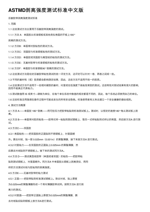
ASTMD剥离强度测试标准中⽂版压敏胶带剥离强度测试标准1. 范围1.1 这些测试⽅法主要⽤于压敏胶带剥离强度的测试。
1.1.1 ⽅法 A:单⾯胶从标准钢板或其他类似表⾯的平板上180°剥离的测试⽅法。
1.1.2 ⽅法B:单⾯背衬胶粘性的测试⽅法。
1.1.3 ⽅法C:双⾯胶与标准钢板粘性的测试⽅法。
1.1.4 ⽅法D:单⾯胶或双⾯胶与离型纸的粘性的测试⽅法。
1.1.5 ⽅法E:⽆基材胶带与标准钢板的粘性的测试⽅法。
1.1.6 ⽅法F:单⾯胶与标准钢板90°剥离的测试⽅法。
1.2 这些测试⽅法是给定压敏胶带粘性测试的统⼀评定⽅法,这评定可以针对⼀卷,两卷之间或⼀批。
1.3 不同的基材和(或)胶质都会影响测定结果,因此,这些⽅法不适⽤不统⼀的胶质。
1.4 这些测试⽅法不适⽤于⼀些相对硬质的基材、衬⾥或在低强度下⾼粘性背胶的测试。
这些特性对测试结果有很⼤的影响,因⽽不能真正代表粘⼒。
1.5 测试数值⽤ IS 或英⼨—磅做为单位,在每个单位系统中数值的规定都是不同的,因此,每个系统必须使⽤⾃⼰的单位。
1.6 这些标准没⽤强调在操作过程中可能会发⽣的所有安全隐患。
标准使⽤者有义务去建⽴⼀个安全健康的操纵规则。
4. 测试⽅法概要4.1 ⽅法 A——单⾯胶 180°剥离——⽤可控压⼒把胶带粘贴到标准测试板上。
测试时,以恒定的速度180°⾓从测试板上剥离。
4.2 ⽅法 B——单⾯背衬胶的粘性——胶带式样⼀粘贴到测试钢板上,取另⼀式样粘贴到式样以的背⾯,然后按⽅法A 进⾏测试。
4.3 ⽅法C——双⾯胶4.3.1 表⾯粘性——把双⾯胶的正⾯贴到不锈钢板上,衬⾥⾯朝外。
撕去衬纸,贴⼀层 0.025mm(0.001in)的聚酯薄膜,接下来按⽅法A 进⾏测试。
4.3.2 衬⾥粘⼒——在双⾯胶的正⾯贴上0.025mm 的聚酯薄膜,然后撕去衬纸贴到不锈钢板上。
接下来的测试同⽅法A。
4.4 ⽅法 D——测试离型纸胶带(单⾯或者双⾯)的粘性——把胶带粘贴到测试钢板上,衬⾥⾯朝外。

ASTMD标准中文版本.docxASTM D412 DIEC标准中文版硫化橡胶和热塑性弹性体拉伸试验方法1简述1.1本试验方法包括了硫化热固性橡胶和热塑性弹性体拉伸性能的评定方法。
本试验方法不能用来试验硬质胶和高硬度、低伸长的材料。
试验方法如下:方法 A——直条和哑铃试样方法 B——环形试样注 1——这两种试验的结果不可比。
1.2 基于 SI 或非 SI 的单位制均视为本标准的标准单位。
由于使用不同单位制的结果数值可能不同,因此不同单位应单独使用,不能混用。
1.3安全性2引用文献D 1349橡胶规范——试验标准温度D 1566橡胶相关术语D 3182 橡胶规范——制取标准混炼胶和标准硫化试片的的材料、设备和操作步骤D 3183橡胶规范——从成品上制备试片D 4483橡胶与碳黑工业种标准试验方法的测量精度规范2.2 ASTM附件环形试样的制取,方法B2.3 ISO 标准ISO 37 硫化或热塑性橡胶拉伸应力—应变性能的测定方法3术语3.1 定义3.1.1 拉伸永久变形——试样在因一定作用下伸长后,在作用力解除的情况下其残余的变形,以原始长度的百分数表示。
3.1.2扯断永久变形——将拉断后的哑铃试样以断面紧贴,测得的永久变形。
3.1.3拉伸力——试样拉断过程中产生的最大力。
3.1.4拉伸强度——拉伸试样时使用的应力3.1.5定伸应力——规则截面的试样,拉伸到特定长度时产生的应力。
3.1.6热塑性弹性体——一种类似与橡胶的材料,但与普通的硫化胶不同,他可象塑料一样的被加工和回收。
3.1.7断裂伸长——在连续的拉伸过程中,试样发生断裂时的伸长率。
3.1.8屈服点——在应力-应变曲线上,在试样最终的破坏前,关于应变的应力变化的速度变为 0 并且相反的点。
3.1.9屈服应变——屈服点的应变的水平3.1.10屈服应力——屈服点的应力的水平4方法描述4.1 测定拉伸性能的试验,首先从样品材料上裁取试样,包括制样和试验两部分。
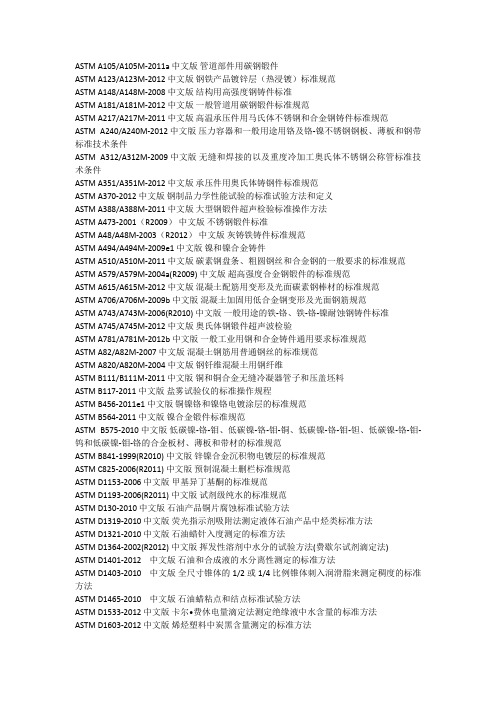
ASTM A105/A105M-2011a中文版管道部件用碳钢锻件ASTM A123/A123M-2012中文版钢铁产品镀锌层(热浸镀)标准规范ASTM A148/A148M-2008中文版结构用高强度钢铸件标准ASTM A181/A181M-2012中文版一般管道用碳钢锻件标准规范ASTM A217/A217M-2011中文版高温承压件用马氏体不锈钢和合金钢铸件标准规范ASTM A240/A240M-2012中文版压力容器和一般用途用铬及铬-镍不锈钢钢板、薄板和钢带标准技术条件ASTM A312/A312M-2009中文版无缝和焊接的以及重度冷加工奥氏体不锈钢公称管标准技术条件ASTM A351/A351M-2012中文版承压件用奥氏体铸钢件标准规范ASTM A370-2012中文版钢制品力学性能试验的标准试验方法和定义ASTM A388/A388M-2011中文版大型钢锻件超声检验标准操作方法ASTM A473-2001(R2009)中文版不锈钢锻件标准ASTM A48/A48M-2003(R2012)中文版灰铸铁铸件标准规范ASTM A494/A494M-2009e1中文版镍和镍合金铸件ASTM A510/A510M-2011中文版碳素钢盘条、粗圆钢丝和合金钢的一般要求的标准规范ASTM A579/A579M-2004a(R2009)中文版超高强度合金钢锻件的标准规范ASTM A615/A615M-2012中文版混凝土配筋用变形及光面碳素钢棒材的标准规范ASTM A706/A706M-2009b中文版混凝土加固用低合金钢变形及光面钢筋规范ASTM A743/A743M-2006(R2010)中文版一般用途的铁-铬、铁-铬-镍耐蚀钢铸件标准ASTM A745/A745M-2012中文版奥氏体钢锻件超声波检验ASTM A781/A781M-2012b中文版一般工业用钢和合金铸件通用要求标准规范ASTM A82/A82M-2007中文版混凝土钢筋用普通钢丝的标准规范ASTM A820/A820M-2004中文版钢钎维混凝土用钢纤维ASTM B111/B111M-2011中文版铜和铜合金无缝冷凝器管子和压盖坯料ASTM B117-2011中文版盐雾试验仪的标准操作规程ASTM B456-2011e1中文版铜镍铬和镍铬电镀涂层的标准规范ASTM B564-2011中文版镍合金锻件标准规范ASTM B575-2010中文版低碳镍-铬-钼、低碳镍-铬-钼-铜、低碳镍-铬-钼-钽、低碳镍-铬-钼-钨和低碳镍-钼-铬的合金板材、薄板和带材的标准规范ASTM B841-1999(R2010)中文版锌镍合金沉积物电镀层的标准规范ASTM C825-2006(R2011)中文版预制混凝土删栏标准规范ASTM D1153-2006中文版甲基异丁基酮的标准规范ASTM D1193-2006(R2011)中文版试剂级纯水的标准规范ASTM D130-2010中文版石油产品铜片腐蚀标准试验方法ASTM D1319-2010中文版荧光指示剂吸附法测定液体石油产品中烃类标准方法ASTM D1321-2010中文版石油蜡针入度测定的标准方法ASTM D1364-2002(R2012)中文版挥发性溶剂中水分的试验方法(费歇尔试剂滴定法)ASTM D1401-2012中文版石油和合成液的水分离性测定的标准方法ASTM D1403-2010中文版全尺寸锥体的1/2或1/4比例锥体刺入润滑脂来测定稠度的标准方法ASTM D1465-2010中文版石油蜡粘点和结点标准试验方法ASTM D1533-2012中文版卡尔•费休电量滴定法测定绝缘液中水含量的标准方法ASTM D1603-2012中文版烯烃塑料中炭黑含量测定的标准方法ASTM D1796-2011中文版离心法测定燃油中水和沉淀物的标准方法ASTM D1840-2007中文版紫外分光光度法测定航空涡轮燃料中萘系烃含量的标准方法ASTM D217-2010中文版润滑脂锥入度测定的标准方法ASTM D2269-2010中文版紫外吸光度评定白油的标准方法ASTM D2270-2010e1中文版根据40℃和100℃下运动粘度计算粘度指数的标准规程ASTM D2272-2011中文版润滑油氧化安定性的测定——旋转氧弹法标准试验方法ASTM D2274-2010中文版馏分燃料油氧化安定性测定的标准方法(加速法)ASTM D240-2009中文版用弹式量热计测定液烃燃料燃烧热的试验方法ASTM D2425-2004(2009)中文版质谱法测量中间馏分烃类组成的标准方法ASTM D2638-2010中文版用氦气体密度仪测定煅烧石油焦真密度的标准方法ASTM D2887-2008中文版用气相色谱分析法测定石油馏分沸程分布的标准试验方法ASTM D2896-2011中文版用高氯酸电位滴定法测定石油产品碱值的试验方法ASTM D3237-2012中文版原子吸收光谱法测定汽油中铅含量的试验方法ASTM D3242-2011中文版航空涡轮燃料酸度标准试验方法ASTM D3329-2003(2009)中文版用气相色谱法测定甲基异丁基酮纯度的试验方法ASTM D3606-2010中文版气相色谱法测定车用汽油和航空汽油中苯和甲苯含量的标准方法ASTM D381-2012中文版喷射蒸汽法测定燃料胶质含量的标准方法ASTM D3829-2002(2007)中文版预测发动机油边界泵送温度的标准方法ASTM D4292-2010中文版煅烧石油焦振动松密度的标准测试方法ASTM D4422-2003(2008)中文版石油焦分析中灰分的测试标准方法ASTM D4530-2011中文版微量法测定残炭的标准方法ASTM D473-2007 中文版抽提法测定燃油和原油中沉淀物的标准方法ASTM D4815-2009中文版气相色谱法测定汽油中甲基叔丁基醚、乙基叔丁基醚、叔戊基甲基醚、二异丙基醚、叔戊醇及C1-C4醇类的标准方法ASTM D4931-2006(2011)中文版生石油焦中总水分的标准测试方法ASTM D4952-2012中文版定性分析燃料和溶剂中活性硫的标准试验方法(Doctor试验)ASTM D5116-2010中文版通过小型环境室测定室内材料/产品的有机排放物的标准指南ASTM D524-2010中文版石油产品兰氏法测定残炭标准方法ASTM D5293-2010e1中文版用冷起动模拟装置测量-5至-30℃发动机油表观粘度的标准方法ASTM D5709-2009中文版石油焦筛析的标准测试方法ASTM D5762-2012中文版石油和石油产品中氮含量的测定舟进样化学发光法ASTM D6376-2010中文版通过波长色散X射线荧光谱测定石油焦中痕量金属的试验方法ASTM D6584-2010ae1中文版气相色谱法测定B-100生物柴油脂肪酸甲酯中游离甘油和总甘油含量的试验方法ASTM D892-2011a中文版润滑油泡末特性标准试验方法ASTM D893-2012中文版用过的润滑油不溶物测定法ASTM E10-2012中文版金属材料布氏硬度的标准试验方法ASTM E1316-2011b中文版无损检测的标准术语ASTM E140-2007中文版金属的标准硬度转换表布氏硬度、维氏硬度、洛氏硬度、表面硬度、努氏硬度和肖氏硬度之间的关系ASTM E165/E165M-2012中文版通用工业液体渗透检验的标准操作方法ASTM E1742/E1742M-2011中文版射线照相检测标准规程ASTM E18-2011中文版金属材料洛氏硬度标准测试方法ASTM E190-1992(R2008)中文版焊缝塑性的导向弯曲试验的标准试验方法ASTM E290-2009中文版金属材料延性弯曲试验的标准试验方法ASTM E317-2011中文版不采用电子测量仪器评价脉冲回波式超声检测系统工作性能的方法ASTM E384-2011e1中文版材料的努氏和维氏硬度标准试验方法ASTM E4-2010中文版测试仪力验正标准规程ASTM E428-2008中文版超声检测用钢质参考试块的制作与质量控制方法ASTM E587-2010中文版接触式超声斜射检测方法ASTM E8/E8M-2011中文版金属材料拉伸试验方法ASTM F136-2012中文版外科植入用Ti-6Al-4V ELI(超低间隙)锻造合金标准(UNS R56401) ASTM F138-2008中文版外科植入物用锻造18铬-14镍-2.5 钼不锈钢棒材和线材标准(UNS S31673)ASTM F1472-2008e1中文版外科植入物用锻造Ti-6Al-4V钛合金标准ASTM F1537-2011中文版外科植入物用锻造Co-28Cr-6Mo合金标准(UNS R31537,UNS R31538和UNS R31539)ASTM F1580-2012中文版外科植入物涂层用钛和Ti-6AL-4V合金粉末标准ASTM F620-2011中文版外科植入物用α+β态钛合金锻件标准ASTM F648-2010a中文版外科植入物用超高分子量聚乙烯粉末和制成物的标准规范ASTM F75-2012中文版外科植入物用Co-28Cr-6Mo合金铸件和铸造合金标准(UNS R30075) ASTM F799-2011中文版外科植入物用Co-28Cr-6Mo合金锻件标准(UNS R31537,R31538,R31539)。

胶粘剂拉伸强度试验标准在胶接接头受拉伸应力作用时,有三种不同的接头受力方式。
(1)拉伸应力与胶接面互相垂直,并且通过胶接面中心均匀地分布在整个胶接面上,这一应力均匀拉伸应力,又称正拉伸应力。
(2)拉伸应力分布在整个胶接面上,但力呈不均匀分布,此种情况称为不均匀拉伸。
(3)与不均匀拉伸相比,它的力作用线不是捅咕试样中心,而偏于试样的一端;它的受力面不是对称的,而是不对称的,这种拉伸叫不对称拉伸,人们有时将这一试验叫撕离试验或劈裂试验,以示与剥离相区别。
一.拉伸强度试验(条型和棒状)拉伸强度试验又叫正拉强度试验或均匀扯离强度试验。
1.原理由两根棒状被粘物对接构成的接头,其胶接面和试样纵轴垂直,拉伸力通过试样纵轴传至胶接面直至破坏,以单位胶接面积所承受的最大载荷计算其拉伸强度。
2.仪器设备拉力试验机应能保证恒定的拉伸速度,破坏负荷应在所选刻度盘容量的10% -90%围。
拉力机的响应时间应短至不影响测量精度,应能测得试样断裂时的破坏载荷,其测量误差不大于1%。
拉力试验机应具有加载时可与试样的轴线和加载方向保持一致的,自动对中的拉伸夹具。
固化夹具,能施加固定压力,保证正确胶接与定位。
3.试验步骤(1)试棒与试样试棒为具有规定形状,尺寸的棒状被粘物。
试样为将两个试棒通过一定工艺条件胶接而成的被测件。
除非另有规定,其试棒尺寸见表8-4。
其试样尺寸的选择视待测胶黏剂的强度,拉力机的满量程,试棒本身材质的强度以及试验时环境因素而定。
表8-4 圆柱形与方形试棒尺寸用于试棒加工的金属材料有45号钢,LY12CZ铝合金,铜,H62黄铜等。
非金属材料有层压塑料等。
层压制品试棒,其层压平面应与试棒一个侧面平行,试棒上的销孔应与层压平面垂直。
试棒的表面处理,涂胶及试样制备工艺,应符合产品标准规定。
胶接好试样,以周围略有一圈细胶梗为宜,此时不必清除,若需清除余胶,则应在固化后进行。
(2)试验在正常状态下,金属试样从试样制备完毕到测试之间,最短停放时间为16h,最长为1个月,非金属试样至少停放40h。

ASTMD标准中文版ASTM D412 DIEC标准中文版硫化橡胶和热塑性弹性体拉伸试验方法1 简述1.1 本试验方法包括了硫化热固性橡胶和热塑性弹性体拉伸性能的评定方法。
本试验方法不能用来试验硬质胶和高硬度、低伸长的材料。
试验方法如下:方法A——直条和哑铃试样方法B——环形试样注1——这两种试验的结果不可比。
1.2 基于SI或非SI的单位制均视为本标准的标准单位。
由于使用不同单位制的结果数值可能不同,因此不同单位应单独使用,不能混用。
1.3 安全性2 引用文献D 1349 橡胶规范——试验标准温度D 1566 橡胶相关术语D 3182 橡胶规范——制取标准混炼胶和标准硫化试片的的材料、设备和操作步骤D 3183 橡胶规范——从成品上制备试片D 4483 橡胶与碳黑工业种标准试验方法的测量精度规范2.2 ASTM 附件环形试样的制取,方法B2.3 ISO 标准ISO 37 硫化或热塑性橡胶拉伸应力—应变性能的测定方法3 术语3.1 定义3.1.1 拉伸永久变形——试样在因一定作用下伸长后,在作用力解除的情况下其残余的变形,以原始长度的百分数表示。
3.1.2 扯断永久变形——将拉断后的哑铃试样以断面紧贴,测得的永久变形。
3.1.3 拉伸力——试样拉断过程中产生的最大力。
3.1.4 拉伸强度——拉伸试样时使用的应力3.1.5 定伸应力——规则截面的试样,拉伸到特定长度时产生的应力。
3.1.6 热塑性弹性体——一种类似与橡胶的材料,但与普通的硫化胶不同,他可象塑料一样的被加工和回收。
3.1.7 断裂伸长——在连续的拉伸过程中,试样发生断裂时的伸长率。
3.1.8 屈服点——在应力-应变曲线上,在试样最终的破坏前,关于应变的应力变化的速度变为0并且相反的点。
3.1.9 屈服应变——屈服点的应变的水平3.1.10 屈服应力——屈服点的应力的水平4 方法描述4.1 测定拉伸性能的试验,首先从样品材料上裁取试样,包括制样和试验两部分。

B36/B36M Specification for Brass Plate,Sheet,Strip,and Rolled Bar3B152Specification for Copper Sheet,Strip,Plate,and Rolled Bar3B209Specification for Aluminum and Aluminum-Alloy Sheet and Plate4B265Specification for Titanium and Titanium Alloy Strip, Sheet,and Plate5D907Terminology of Adhesives6D4896Guide for Use of Adhesive-Bonded Single Lap-Joint Specimen Test Results6E4Practices for Force Verification of Testing Machines7 3.Terminology3.1Definitions—Many terms in this test method are defined in Terminology D907.4.Significance and Use4.1This test method is primarily comparative.However,it does have application as a discriminator in determining varia-tions in adherend surface preparation parameters and adhesive environmental durability.The test method has found applica-tions in controlling surface preparations,primer,and adhesive systems for determining strength properties of tested systems.4.2The misuse of strength values obtained from this test method as design-allowable stress values for structural joints could lead to product failure,property damage,and human injury.The apparent shear strength of an adhesive obtained from a given small single-lap specimen may differ from that obtained from a joint made with different adherends or by a different bonding process.The normal variation of temperature and moisture in the service environment causes the adherends and the adhesive to swell or shrink.The adherends and adhesive are likely to have different thermal and moisture coefficients of expansion.4.3Even in small specimens,short-term environmental changes may induce internal stresses or chemical changes in the adhesive that permanently affect the apparent strength and other mechanical properties of the adhesive.The problem of predicting joint behavior in a changing environment is even more difficult if a different type of adherend is used in a larger structural joint than was used in the small specimen.4.4The apparent shear strength measured with a single-lap specimen is not suitable for determining design-allowable stresses for designing structural joints that differ in any manner from the joints tested without thorough analysis and under-standing of the joint and adhesive behaviors.4.5Single-lap tests may be used for comparing and select-ing adhesives or bonding processes for susceptibility to fatigue and environmental changes,but such comparisons must be made with great caution since different adhesives may respond differently in different joints.See Guide D4896for further discussion of the concepts relative to interpretation of adhesive-bonded single-lap-joints.5.Apparatus5.1The testing machine shall conform to the requirements of Practices E4.The testing machine shall be so selected that the breaking load of the specimens falls between15and85 percent of the full-scale capacity.The machine shall be capable of maintaining a rate of loading of80to100kg/cm2(1200to 1400psi)/min,or,if the rate is dependent on crosshead motion, the machine should be set to approach this rate of loading, approximately0.05in./min.It shall be provided with a suitable pair of self-aligning grips to hold the specimen.It is recom-mended that the jaws of these grips shall engage the outer25 mm(1in.)of each end of the test specimenfirmly.5.2The grips and attachments shall be so constructed that they will move into alignment with the test specimen as soon as the load is applied,so that the long axis of the test specimen will coincide with the direction of the applied pull through the center line of the grip assembly.5.3The length of overlap of the specimen may be varied where necessary.The length of the specimen in the jaws, however,must not be varied.The distance from the end of the lap to the end of the jaws should be63mm(21⁄2in.)in all tests.6.Test Specimens6.1Test specimens shall conform to the form and dimen-sions shown in Fig.1.These shall be cut from test panels prepared as prescribed in Section7.The recommended thick-ness of the sheets is1.6260.125mm(0.06460.005in.).The recommended length ofoverlap for most metals of1.62mm(0.064in.)in thickness is12.760.25mm(0.560.01in.).6.2Since it is undesirable to exceed the yield point of themetal in tension during test,the permissible length of overlapin the specimen will vary with the thickness and type of metal,and on the general level of strength of the adhesive beinginvestigated.The maximum permissible length may be com-puted from the following relationship:L5Fty t/t(1)where:L=length of overlap,in.,t=thickness of metal,in.,Fty=yield point of metal(or the stress at proportionallimit),psi,andt=150percent of the estimated average shear strengthin adhesive bond,psi.6.3A variation in thickness of the metal,and the length ofoverlap,will likely influence the test values and make directcomparison of data questionable.For this reason,in compara-tive or specification tests,the thickness should preferably be1.6260.125mm(0.06460.005in.)and the length of overlap3Annual Book of ASTM Standards,V ol02.01.4Annual Book of ASTM Standards,V ol02.02.5Annual Book of ASTM Standards,V ol02.04.6Annual Book of ASTM Standards,V ol15.06.7Annual Book of ASTM Standards,V ol03.01.FIG.1Form and Dimensions of Test Specimenshould preferably be12.760.25mm(0.560.01in.),or not in excess of the value computed in6.2.For development tests values could be different,but should then be constant.6.4The following grades of metal are recommended for the test specimens:Metal ASTM DesignationBrass B36,C26800(Alloy8)Copper B152,C11000Aluminum B209,Alloy2024,T3temperSteel A109,Grade2Corrosion-resisting steel A167,Type302Titanium B2656.5At least30specimens shall be tested,representing at least four different joints.However,if statistical analysis of data and variance is employed,it should be possible to reduce this number.7.Preparation of Test Joints7.1It is recommended that test specimens be made up in multiples of at leastfive specimens,and then cut into indi-vidual test specimens(Note1),Fig.2and Fig.3.Cut sheets of the metals prescribed in6.1and6.4to suitable size.All edges of the metal panels and specimens which will be within(or which will bound)the lap joints shall be machined true (without burrs or bevels and at right angles to faces)and smooth(rms160max)before the panels are surface-treated and bonded.Clean and dry the sheets carefully,according to the procedure prescribed by the manufacturer of the adhesive, and assemble in pairs.Prepare and apply the adhesive accord-ing to the recommendations of the manufacturer of the adhe-sive.Apply the adhesive to a sufficient length in the areaacross FIG.2Standard TestPanelthe end of one or both metal sheets so that the adhesive willcover a space approximately 6mm (1⁄4in.)longer than theoverlap as selected in Section 6.Assemble the sheets so thatthey will be held rigidly so that the length of the overlap willbe controlled,as indicated in Section 6,within 0.25mm(60.01in.),and the adhesive allowed to cure as prescribed bythe manufacturer of the adhesive.N OTE 1—Bonding specimens in multiple panels is believed to givemore representative specimens.However,individual specimens may beprepared if agreeable to the supplier or the purchaser of the adhesive.8.Preparation of Test Specimens8.1Cut the test specimens,as shown in Fig.1,from thepanels,Figs.2and 3.Perform the cutting operation so as toavoid overheating or mechanical damage to the joints (Note 2).For final preparation trim panel area according to Fig. 2.Measure the width of the specimen and the length of theoverlap to the nearest 0.25mm (0.01in.)to determine the sheararea.N OTE 2—A five-tooth,typesetter’s circular saw has been found suitablefor such purposes.9.Procedure9.1Test the specimens,prepared as prescribed in Section 8,as soon after preparation as possible.The manufacturer of the adhesive may,however,prescribe a definite period of condi-tioning under specific conditions before testing.9.2Place the specimens in the grips of the testing machine so that the outer 25mm (1in.)of each end are in contact with the jaws (see 5.3)and so that the long axis of the test specimen coincides with the direction of applied pull through the center line of the grip assembly.Apply the loading immediately to the specimen at the rate of 80to 100kg/cm 2(1200to 1400psi)of the shear area per min.Continue the load to failure.This rate of loading will be approximated by a free crosshead speed of 1.3mm (0.05in.)/min.10.Calculations 10.1Record the load at failure and the nature and amount of this failure (cohesion in adhesive or metal,or adhesion)for each specimen.Express all failing loads in kilograms per square centimeter (pounds per square inch)of shear area,calculated to the nearest 0.06cm 2(0.01in.2).11.Report 11.1Report the following:11.1.1Complete identification of the adhesive tested,in-cluding type,source,date manufactured,manufacturers’code numbers,form,etc.,11.1.2Complete identification of the metal used,its thick-ness,and the method of cleaning and preparing its surfaces prior to bonding,11.1.3Application andbonding conditions used in prepar-ing specimens,11.1.4Average thickness of adhesive layer after formation of the joint within 0.001in.(0.025mm).The method of obtaining the thickness of the adhesive layer shall be described including procedure,location of measurements,and range of measurements.11.1.5Length of overlap used,11.1.6Conditioning procedure used for specimens prior to testing,11.1.7Number of specimens tested,11.1.8Number of joints represented and type of joint if other than single overlap,11.1.9Maximum,minimum,and average values for the failing load,and 11.1.10The nature of the failure,including the average estimated percentages of failure in the cohesion of the adhe-sive,contact failure,and adhesion to the metal.12.Precision and Bias 12.1The precision and bias statement for this test method has not been determined yet.Archival and round-robin infor-mation is being reviewed,and the results are expected by September 2004.13.Keywords 13.1adhesives;metal-to-metal;shear strength;single-lap joint;tension loadingFIG.3Optional Panel for Acceptance Tests OnlyThe American Society for Testing and Materials takes no position respecting the validity of any patent rights asserted in connection with any item mentioned in this ers of this standard are expressly advised that determination of the validity of any such patent rights,and the risk of infringement of such rights,are entirely their own responsibility.This standard is subject to revision at any time by the responsible technical committee and must be reviewed everyfive years and if not revised,either reapproved or withdrawn.Your comments are invited either for revision of this standard or for additional standards and should be addressed to ASTM Headquarters.Your comments will receive careful consideration at a meeting of the responsible technical committee,which you may attend.If you feel that your comments have not received a fair hearing you should make your views known to the ASTM Committee on Standards,at the address shown below.This standard is copyrighted by ASTM,100Barr Harbor Drive,PO Box C700,West Conshohocken,PA19428-2959,United States. Individual reprints(single or multiple copies)of this standard may be obtained by contacting ASTM at the above address or at 610-832-9585(phone),610-832-9555(fax),or service@(e-mail);or through the ASTM website().。

D412硫化橡胶和热塑性弹性体拉伸试验方法1简述1.1本试验方法包括了硫化热固性橡胶和热塑性弹性体拉伸性能的评定方法。
本试验方法不能用来试验硬质胶和高硬度、低伸长的材料。
试验方法如下:方法A——直条和哑铃试样方法B——环形试样注1——这两种试验的结果不可比。
1.2基于SI或非SI的单位制均视为本标准的标准单位。
由于使用不同单位制的结果数值可能不同,因此不同单位应单独使用,不能混用。
1.3安全性2引用文献D1349橡胶规范——试验标准温度D1566橡胶相关术语D3182橡胶规范——制取标准混炼胶和标准硫化试片的的材料、设备和操作步骤D3183橡胶规范——从成品上制备试片D4483橡胶与碳黑工业种标准试验方法的测量精度规范2.2ASTM附件环形试样的制取,方法B2.3ISO标准ISO37硫化或热塑性橡胶拉伸应力—应变性能的测定方法3术语3.1定义3.1.1拉伸永久变形——试样在因一定作用下伸长后,在作用力解除的情况下其残余的变形,以原始长度的百分数表示。
3.1.2扯断永久变形——将拉断后的哑铃试样以断面紧贴,测得的永久变形。
3.1.3拉伸力——试样拉断过程中产生的最大力。
3.1.4拉伸强度——拉伸试样时使用的应力3.1.5定伸应力——规则截面的试样,拉伸到特定长度时产生的应力。
3.1.6热塑性弹性体——一种类似与橡胶的材料,但与普通的硫化胶不同,他可象塑料一样的被加工和回收。
3.1.7断裂伸长——在连续的拉伸过程中,试样发生断裂时的伸长率。
3.1.8屈服点——在应力-应变曲线上,在试样最终的破坏前,关于应变的应力变化的速度变为0并且相反的点。
3.1.9屈服应变——屈服点的应变的水平3.1.10屈服应力——屈服点的应力的水平4方法描述4.1测定拉伸性能的试验,首先从样品材料上裁取试样,包括制样和试验两部分。
试样的外形可以是哑铃形、环形或直条形,截面形状规则。
4.2在试样未经预伸的情况下测定拉伸强度、定神应力、屈服点、扯断伸长率。

纤维增强塑料剪切强度测试标准
纤维增强塑料(Fiber-Reinforced Plastics,FRP)的剪切强度测试标准通常是根据国际标准化组织(ISO)、美国材料和试验协会(ASTM)以及其他行业标准制定的。
这些标准用于测量纤维增强塑料在受到剪切力时的性能。
以下是一些常见的用于纤维增强塑料剪切强度测试的标准:
1.ASTM D2344:“ASTM D2344-84”是美国材料和试验协会发布
的标准,用于测定纤维增强复合材料在剪切载荷下的剪切强度。
该标准提供了用于进行拉伸剪切试验的标准方法,以测定材料
的剪切强度和剪切弹性模量。
2.ASTM D5868:“ASTM D5868-01”是另一个ASTM标准,用于
测量具有不同类型和方向纤维增强的塑料复合材料的拉伸剪切
性能。
3.ISO 14129:“ISO 14129:1998”是国际标准化组织发布的标准,
用于测定纤维增强塑料的剪切性能。
该标准提供了进行拉伸剪
切试验的指南,包括试验方法和数据报告。
4.ASTM D3518:“ASTM D3518-94”是ASTM发布的标准,用于
测定树脂基复合材料在剪切荷载下的剪切强度。
该标准包括具
体的试验程序和数据分析方法。
这些标准通常包括了用于制备试样、测试设备、试验程序、数据处理和结果报告的详细指南。
通过按照这些标准进行剪切强度测试,可以评估纤维增强塑料的性能,以确保其在特定应用中的安全性和可靠
性。
在进行测试时,应注意使用适当的设备和遵循标准中的具体测试程序。

ASTM标准的中文版本ASTM标准的中文版本ASTM A6/A6M-2004 a结构用轧制钢板、型钢、板桩和棒钢通用要求ASTM A36/A36M-2004碳结构钢标准规范ASTM A106-2002a高温用无缝碳钢公称管规范ASTM A143-2003热侵镀锌结构钢制品防脆化的标准实施规程和催化探测方法ASTM A179/A179M-1990a(R2001)热交换器和冷凝器用无缝冷拉低碳钢管标准规范ASTM A192-2002高压设备用无缝碳钢锅炉管标准规范ASTM A209/A209M-2003锅炉和过热器用无缝碳钼合金钢管标准规范ASTM A210/A210M-2003锅炉和过热器用无缝中碳钢管技术条件ASTM A213/A213Mb-2004锅炉过热器和换热器用无缝铁素体和奥氏体合金钢传热管技术条件ASTM A234/A234M-2004中、高温用锻制碳钢和合金钢管道配件ASTM A252-98(R2002)焊接钢和无缝钢管桩的标准规范ASTM A262-2002a探测奥氏体不锈钢晶间腐蚀敏感度的标准实施规范ASTM A269/A269-2004通用无缝和焊接奥氏体不锈钢管标准规范ASTM A333/A333M-2004低温设备用无缝和焊接钢管的规范标准ASTM A334/A334M-2004低温设备用无缝和焊接碳素和合金钢管的标准规范ASTM A335-2003高温设备用无缝铁素体合金钢管标准规范ASTM A370/A370M-2003a钢制品力学性能试验方法和定义标准ASTM A387/A387M-2003压力容器用铬钼合金钢板的标准规范ASTM A403/A403M-2004锻制奥氏体不锈钢管配件的标准规范ASTM A450/A450M-2004碳素钢管、铁素体合金钢管及奥氏体合金钢管一般要求的标准规范ASTM A500-2003a圆形与异型冷成型焊接与无缝碳素钢结构管标准规范ASTM A515-2003中温及高温压力容器用碳素钢板的标准规范ASTM A516-2004a中温及低温压力容器用碳素钢板的标准规范ASTM A530-2003特种碳素钢和合金钢管一般要求的标准规范ASTM A615/A615M-2004a混凝土配筋用异形钢筋和无节钢胚棒标准规范ASTM A703/A703M-2004标准技术条件—承压件钢铸件通用要求ASTM A781/A781M-2004a铸件、钢和合金的标准规范及通用工业的一般性要求ASTM A788/A788M-2004a标准技术条件—钢锻件通用要求ASTM B209/B209M -2004铝和铝合金薄板和中厚板标准规范ASTM E6-2003金属材料布氏硬度的标准测试方法ASTM E18-2003金属材料洛氏硬度和洛氏表面硬度的标准测试方法ASTM E29-2002使用有效数字确定试验数据与规范符合性作法ASTM E8-2004金属材料拉伸试验的标准测试方法ASTM E94-2004放射性检查的标准指南ASTM E125-1963(R2003)铁铸件的磁粉检验用标准参考照片ASTM E164-2003焊件的超声接触检验的标准操作规程ASTM E208-1995a(R2000)用导向落锤试验测定铁素体钢无塑性转变温度的标准试验方法ASTM E213-2004金属管超声检验方法ASTM F36-1995测定垫片材料压缩率及回弹率的标准试验方法ASTM F37-1995垫片材料密封性的标准试验方法ASTM F38-1995垫片材料的蠕变松弛的标准试验方法ASTM F112-1995色覆垫片密封性能的标准试验方法ASTM F146-1995a垫片材料耐液体标准试验方法ASTM F1311-1995(R2001)大口径组装式碳钢法兰标准规范ASTM G1-2003腐蚀试样的制备、清洁处理和评定用标准实施规范ASTM G36-73(R1981) 参考资料标准实用规程:在沸的氯化镁溶液中进行的应力腐蚀裂纹试验ASTM G46-1976(R1986) 参考资料标准实用规程:麻点腐蚀的检验和评定ASTM G48-1976(R1980) 参考资料使用三氯化铁溶液做不锈钢及其合金的耐麻点腐蚀和抗裂口腐蚀性试验的标准方法ASTM标准中译本丛书(一)碳钢、铸铁、不锈钢及合金钢材料标准规范(含18个标准)ASTM A105/A105M-2002管道部件用碳钢锻件ASTM A126-1995(R2001)阀门、法兰和管道附件用灰铁铸件ASTM A181/A181M-2001通用管路用碳钢锻件标准规范ASTM A193/A193M-2001高温用合金钢和不锈钢螺栓材料ASTM A194/A194M-2001 a高温用合金钢和不锈钢螺栓材料ASTM A216/A216M-2001 a高温用可熔焊碳钢铸件标准规范ASTM A217/A217M-2002高温承压件用马氏体不锈钢和合金钢铸件标准规范ASTM A276-2002 a不锈钢棒材和型材ASTM A278/A278M-2001高温不超过650°F(350℃)的承压部件用灰铸铁件ASTM A320/A320M-2002低温用合金钢栓接材料ASTM A350/A350M-2002要求冲击韧性试验的管件用碳钢及低合金钢锻件标准规范ASTM A351/A351M-2000承压件用奥氏体、奥氏体-铁素体(双相)钢铸件规范ASTM A352/A352M-1993(R1998)低温承压件用铁素体和马氏体钢铸件标准规范ASTM A395/A395M-1999高温用铁素体球墨铸铁承压铸件ASTM A439-1983(R1999)奥氏体球墨铸铁件ASTM A536-1984(R1999)球墨铸铁件ASTM A694/A694M-2000高温输送用管法兰、管件、阀门及零件用碳钢和合金钢锻件标准规范ASTM A965/A965M-2002高温高压部件用奥氏体钢锻件ASTM标准中译本丛书(二)法兰、管件、阀门及部件(含9个标准)ASTM A182/A182M-2002高温用锻制或轧制合金钢法兰、锻制管件、阀门和部件ASTM A961-2002管道用钢制法兰、锻制管件、阀门和零件的通用要求标准规范ASTM B462-2002高温耐腐蚀用锻制或轧制的UNS NO6030、UNS NO6022、UNS NO6200、UNS NO8020、UNS NO8024、UNS NO8026、UNS NO8367、UNS NO10276、UNS N10665、UNS N10675和UNS R20033合金管法兰、锻制管件、阀门和零件标准规范ASTM F885-1984公称管径为NPS 1/4~2的青铜截止阀外形尺寸标准规范ASTM F992-1986(R2001)阀门铭牌标准规范ASTM F993-1986(R2001)阀门锁紧装置标准规范ASTM F1030-1986(R1998)阀门操作装置的选择准则ASTM F1098-1987(R1998)公称管径有NPS2~24的蝶阀外形尺寸标准规范ASTM F1565-2000蒸汽用减压阀规范。
通过拉伸载荷(金属- 金属)1单搭接接合粘合金属试样的表观剪切强度1粘合剂粘合强度测试结果的准确度取决于粘合过程的条件。
除非制造商和采购商另有约定,粘合条件应由粘合剂制造商规定。
为了确保向进行测试的个人提供完整的信息,粘合剂制造商应提供以下每个变量的数值和其他具体信息:(1)在施加粘合剂之前制备表面的过程,金属表面的清洁和干燥以及特殊的表面处理例如打磨,其没有特别受限于相关的测试方法。
(2)粘合剂的完全混合方向。
(3)粘合剂的使用条件,包括涂膜的铺展速度或厚度,要涂覆的涂层数量,是否应用于一个或两个表面,以及需要多于一层涂层的干燥条件。
(4)施加压力前的装配条件,包括室温,相对湿度,时间长短以及是否使用开放或封闭装配。
(5)固化条件,包括施加的压力量,压力下的时间长度,施加压力的方法(压力袋,压力盘等),加热速率以及装置的温度压力。
应该说明这个温度是否是粘合线的温度,或者是维持组件的大气温度。
(6)测试前的调节程序,除非规定了标准程序,包括时间长度,温度和相对湿度。
如果测试操作员可以假定任何一个在这个范围内的任意选择的值,或者这些值的几个变量的任何组合都可以被制造商和制造商接受,则粘合剂的制造商可以为任何变量规定一个范围粘合剂的购买者。
1.Scope1.1本测试方法涵盖了在标准单搭接接头试样上以及在特定的制备和测试条件下进行测试时,确定粘合剂粘结金属的剪切强度。
1.2本标准不旨在解决与其使用有关的所有安全问题(如果有的话)。
本标准的使用者有责任建立合适的,1本测试方法由ASTM D14胶粘剂委员会管辖,并且是金属粘接胶粘剂小组委员会D14.80的直接责任。
当前版本于2001年10月10日批准。
2001年12月发布。
最初提供安全和健康实践,并在使用前确定监管限制的适用性。
1.3以SI单位表示的数值被认为是标准。
括号中给出的数值仅供参考。
2.参考文件2.1ASTM标准:A 109冷轧带钢碳钢规范2 A 167不锈钢和耐热钢规范铬镍钢板,薄板和带钢2公布为D 1002 - 49 T.最后一版D 1002 - 99. 2 ASTM标准年鉴,卷01.03。

V型槽轨道剪切方法测复合材料剪切性能测试标准1.范围这篇测试方法适用于确定高模量纤维增强复合材料的剪切性能,V型槽口试样通过加载轨道的两对夹具夹持试样。
当施加拉力时,轨道通过试样表面将剪切载荷传递给试样。
相对而言,测试方法D5379是在试样上下端部施加载荷。
面内加载可以对试样提供更高的剪切载荷。
另外,当前测试方法比D5379使用更大的测试截面积。
在这两种测试方法中,使用V型槽口,相对于夹具附近提高了试样测试截面积的剪切应力。
因此,当V型槽口试样剪应力比未用V型槽口试样分布均匀,实现测试截面部位发生破坏。
测试方法D4255利用两个加载轨道夹持无槽口的试样提供拉伸加载。
和测试方法D4255相比,本文所使用的测试方法在试样夹持时无须在试样表面打孔。
复合材料局限于如下形式的连续纤维或非连续纤维增强构成:层合板由单一方向的纤维层合板构成,纤维排列方向平行或垂直于夹具轨道。
层合板是个对称平衡结构,并且0°方向平行或垂直于夹具轨道。
层合板通过编织物、编制状纤维丝线层合板组成。
短纤维增强材料由大多数按随机分布方式排列的纤维组成。
SI单位和英尺-磅单位制里的数值,被认为是二个独立的数值标准。
本文出现的英尺-磅数值由括号里面标示出来。
这两个标准里面的数值并不完全相等,每个标准里的数值都必须独立使用。
如果把两个标准的数值结合在一起,可能会得到不符合标准的结果。
这个标准不支持所有的安全系数考虑问题,如果实验操作者需要的话必须自行确定。
因此在实验操作之前先做好安全步骤,是实验员实验前做好准备工作的一项重要责任。
2.参考文献美国材料实验协会标准D792 塑料密度和特殊比重(相对密度)位移测定方法D883 塑料专业术语D2584聚氯乙烯树脂烧失量测试方法D2734塑料增强材料失效测试方法D3171 复合材料构成成分的测试方法D3878 复合材料专业术语D4255 通过横杆剪切法测定非平面聚合母体复合材料剪切性能测试方法D5229 母体聚合复合材料的吸水性和平衡条件D5379 通过V字型凹槽梁测试法测定复合材料剪切性能的测试方法D6856 纤维增强织物复合材料的测试指导E4 测试仪器力学检测方案E6 力学测试相关的专业术语E111 杨氏模量、剪切模量、割线模量测试方法E122 计算要求特殊偏差试样尺寸方案,各个性能平均值E177 ASTM测试方法里各项物理量的精度偏差使用方法E251金属连结体电阻应变仪性能测试方法演示E456质量分析相关的专业术语E1237 连接电阻应变仪安装指导E1309确定数据库里纤维增强母体聚合复合材料指导E1434 纤维增强复合材料性能数据指导其它文献ANSI 几何尺寸和偏差ANSI/ASME 表面材质(表面粗糙、起伏、褶皱)美国材料实验协会标准附录:V字型凹槽横杆剪切固定装置示意图3.专业术语定义—D3878专业术语里详细说明了和高模量纤维相关的各项含义以及它们的组成。
胶粘剂拉伸剪切强度国标
胶粘剂的拉伸剪切强度是指在给定的拉伸剪切速率下,胶粘剂能够承受的拉伸剪切应力。
根据国际标准ISO 527-4和国内标准GB/T 528-1998《塑料拉伸性能试验方法》中的相关规定,胶粘剂的拉伸剪切强度国标为:
1. 试验样品的尺寸:ISO 527-4中规定试验样品的标准尺寸为400mm x 10mm,国内标准中没有明确规定标准尺寸,一般可采用ISO 527-4中的尺寸。
2. 试验条件:ISO 527-4中规定试验条件为试验速度为1 ± 0.2 mm/min,试验温度为23±2℃,湿度为50±10%。
国内标准中具体试验条件可根据实际需要进行设定,但一般也参照ISO 527-4的相关规定。
3. 试验方法:拉伸剪切试验可采用试验机进行,测试过程中需保证试样的稳定和正确的负荷应力传递。
需要注意的是,具体的胶粘剂拉伸剪切强度国标可能因不同用途和材料而有所差异,还需参考具体的胶粘剂产品的国家标准或企业标准进行确认。

抗拉强度抗拉强度,表征材料最大均匀塑性变形的抗力,拉伸试样在承受最大拉应力之前,变形是均匀一致的,但超出之后,金属开始出现缩颈现象,即产生集中变形;对于没有(或很小)均匀塑性变形的脆性材料,它反映了材料的断裂抗力。
符号为Rm(GB/T 228-1987旧国标规定抗拉强度符号为σb),单位为MPa。
中文名:抗拉强度外文名:tensile strength本质:材料最大均匀塑性变形的抗力反应:材料的断裂抗力符号:Rm单位:MPaTensile strengthThe tensile strength, the maximum resistance characterization of materials uniform plastic deformation before, tensile specimens under tensile stress, deformation is uniform, but beyond, metal appears necking phenomenon, namely produce concentrated deformation; for there is no (or very small) of brittle materials uniform plastic deformation, it reflects the fracture resistance of materials. Symbol Rm (GB/T 228-1987 old national standard tens ile strength σ B symbols for units), MPaChinese: tensile strengthEnglish Name: tensile strengthThis matter: material maximum uniform plastic deformation resistanceResponse: the fracture resistance of materialsSymbol: RmUnit: MPa抗拉强度(tensile strength)试样拉断前承受的最大标称拉应力。
V型槽轨道剪切方法测复合材料剪切性能测试标准1.范围这篇测试方法适用于确定高模量纤维增强复合材料的剪切性能,V型槽口试样通过加载轨道的两对夹具夹持试样。
当施加拉力时,轨道通过试样表面将剪切载荷传递给试样。
相对而言,测试方法D5379是在试样上下端部施加载荷。
面内加载可以对试样提供更高的剪切载荷。
另外,当前测试方法比D5379使用更大的测试截面积。
在这两种测试方法中,使用V型槽口,相对于夹具附近提高了试样测试截面积的剪切应力。
因此,当V型槽口试样剪应力比未用V型槽口试样分布均匀,实现测试截面部位发生破坏。
测试方法D4255利用两个加载轨道夹持无槽口的试样提供拉伸加载。
和测试方法D4255相比,本文所使用的测试方法在试样夹持时无须在试样表面打孔。
复合材料局限于如下形式的连续纤维或非连续纤维增强构成:层合板由单一方向的纤维层合板构成,纤维排列方向平行或垂直于夹具轨道。
层合板是个对称平衡结构,并且0°方向平行或垂直于夹具轨道。
层合板通过编织物、编制状纤维丝线层合板组成。
短纤维增强材料由大多数按随机分布方式排列的纤维组成。
SI单位和英尺-磅单位制里的数值,被认为是二个独立的数值标准。
本文出现的英尺-磅数值由括号里面标示出来。
这两个标准里面的数值并不完全相等,每个标准里的数值都必须独立使用。
如果把两个标准的数值结合在一起,可能会得到不符合标准的结果。
这个标准不支持所有的安全系数考虑问题,如果实验操作者需要的话必须自行确定。
因此在实验操作之前先做好安全步骤,是实验员实验前做好准备工作的一项重要责任。
2.参考文献美国材料实验协会标准D792 塑料密度和特殊比重(相对密度)位移测定方法D883 塑料专业术语D2584聚氯乙烯树脂烧失量测试方法D2734塑料增强材料失效测试方法D3171 复合材料构成成分的测试方法D3878 复合材料专业术语D4255 通过横杆剪切法测定非平面聚合母体复合材料剪切性能测试方法D5229 母体聚合复合材料的吸水性和平衡条件D5379 通过V字型凹槽梁测试法测定复合材料剪切性能的测试方法D6856 纤维增强织物复合材料的测试指导E4 测试仪器力学检测方案E6 力学测试相关的专业术语E111 杨氏模量、剪切模量、割线模量测试方法E122 计算要求特殊偏差试样尺寸方案,各个性能平均值E177 ASTM测试方法里各项物理量的精度偏差使用方法E251金属连结体电阻应变仪性能测试方法演示E456质量分析相关的专业术语E1237 连接电阻应变仪安装指导E1309确定数据库里纤维增强母体聚合复合材料指导E1434 纤维增强复合材料性能数据指导其它文献ANSI 几何尺寸和偏差ANSI/ASME 表面材质(表面粗糙、起伏、褶皱)美国材料实验协会标准附录:V字型凹槽横杆剪切固定装置示意图3.专业术语定义—D3878专业术语里详细说明了和高模量纤维相关的各项含义以及它们的组成。
通过拉伸载荷(金属- 金属) 1 单搭接接合粘合金属试样的表观剪切强度 1 粘合剂粘合强度测试结果的准确度取决于粘合过程的条件。
除非制造商和采购商另有约定,粘合条件应由粘合剂制造商规定。
为了确保向进行测试的个人提供完整的信息,粘合剂制造商应提供以下每个变量的数值和其他具体信息:(1)在施加粘合剂之前制备表面的过程,金属表面的清洁和干燥以及特殊的表面处理例如打磨,其没有特别受限于相关的测试方法。
(2)粘合剂的完全混合方向。
(3)粘合剂的使用条件,包括涂膜的铺展速度或厚度,要涂覆的涂层数量,是否应用于一个或两个表面,以及需要多于一层涂层的干燥条件。
(4)施加压力前的装配条件,包括室温,相对湿度,时间长短以及是否使用开放或封闭装配。
(5)固化条件,包括施加的压力量,压力下的时间长度,施加压力的方法(压力袋,压力盘等),加热速率以及装置的温度压力。
应该说明这个温度是否是粘合线的温度,或者是维持组件的大气温度。
(6)测试前的调节程序,除非规定了标准程序,包括时间长度,温度和相对湿度。
如果测试操作员可以假定任何一个在这个范围内的任意选择的值,或者这些值的几个变量的任何组合都可以被制造商和制造商接受,则粘合剂的制造商可以为任何变量规定一个范围粘合剂的购买者。
1.Scope1.1 本测试方法涵盖了在标准单搭接接头试样上以及在特定的制备和测试条件下进行测试时,确定粘合剂粘结金属的剪切强度。
1.2 本标准不旨在解决与其使用有关的所有安全问题(如果有的话)。
本标准的使用者有责任建立合适的,1 本测试方法由ASTM D14 胶粘剂委员会管辖,并且是金属粘接胶粘剂小组委员会D14.80 的直接责任。
当前版本于2001 年10 月10 日批准。
2001 年12 月发布。
最初提供安全和健康实践,并在使用前确定监管限制的适用性。
1.3以SI单位表示的数值被认为是标准。
括号中给出的数值仅供参考。
2. 参考文件2.1ASTM 标准:A 109 冷轧带钢碳钢规范2 A 167 不锈钢和耐热钢规范铬镍钢板,薄板和带钢2公布为 D 1002 - 49 T.最后一版 D 1002 - 99. 2 ASTM 标准年鉴,卷01.03。

拉伸强度检测相关标准(总2页)-CAL-FENGHAI.-(YICAI)-Company One1-CAL-本页仅作为文档封面,使用请直接删除拉伸强度检测相关标准拉伸强度(tensile strength)是指材料产生最大均匀塑性变形的应力。
(1)在拉伸试验中,试样直至断裂为止所受的最大拉伸应力即为拉伸强度,其结果以MPa表示。
有些错误地称之为抗张强度、抗拉强度等。
(2)用仪器测试样拉伸强度时,可以一并获得拉伸断裂应力、拉伸屈服应力、断裂伸长率等数据。
(3)拉伸强度的计算:σt = p /( b×d) 式中,σt为拉伸强度(MPa);p为最大负荷(N);b为试样宽度(mm);d为试样厚度(mm)。
科标无机实验室专业提供检测指标:弹性指标、硬度指标、强度指标、塑性指标、韧性指标、疲劳性能、断裂韧度。
(001)(15.05.19)检测标准:BB/T 0002-2008 双向拉伸聚丙烯珠光薄膜BB/T 0024-2004 运输包装用拉伸缠绕膜CB/T 3457-1992 液压拉伸器CSM 01 01 02 01-2006 金属材料室温拉伸试验测量结果不确定度评定CSM 01 01 02 02-2006 金属拉伸杨氏模量(静态法)测量结果不确定度评定DB13/T 1355-2010 锦纶6综丝拉伸性能的测定DB15/T 456-2009 牧草拉伸膜裹包青贮技术规程DB37/T 2263-2012 硫化橡胶拉伸弹性模量的测定DB53/T 644-2014 烟叶抗张强度的测定恒速拉伸法DB53/T 80-2008 烟用双向拉伸聚丙烯薄膜FZ/T 01031-1993 针织物和弹性机织物接缝强力和伸长率的测定抓样拉伸法FZ/T 01034-2008 纺织品机织物拉伸弹性试验方法FZ/T 01114-2012 织物低应力拉伸性能的试验方法FZ/T 50006-2013 氨纶丝拉伸性能试验方法FZ/T 60037-2013 膜结构用涂层织物拉伸蠕变性能试验方法FZ/T 60041-2014 树脂基三维编织复合材料拉伸性能试验方法FZ/T 70006-2004 针织物拉伸弹性回复率试验方法FZ/T 75004-2014 涂层织物拉伸伸长和永久变形试验方法GB/T 10003-2008 普通用途双向拉伸聚丙烯(BOPP)薄膜GB/T 10120-2013 金属材料拉伸应力松弛试验方法GB/T 1040.1-2006 塑料拉伸性能的测定第1部分:总则GB/T 1040.2-2006 塑料拉伸性能的测定第2部分:模塑和挤塑塑料的试验条件GB/T 1040.3-2006 塑料拉伸性能的测定第3部分:薄膜和薄片的试验条件GB/T 1040.4-2006 塑料拉伸性能的测定第4部分:各向同性和正交各向异性纤维增强复合材料的试验条件GB/T 1040.5-2008 塑料拉伸性能的测定第5部分:单向纤维增强复合材料的试验条件GB/T 10573-1989 有色金属细丝拉伸试验方法GB/T 10654-2001 高聚物多孔弹性材料拉伸强度和拉断伸长率的测定GB/T 11546.1-2008 塑料蠕变性能的测定第1部分:拉伸蠕变GB/T 1239.1-2009 冷卷圆柱螺旋弹簧技术条件第1部分:拉伸弹簧GB/T 12683-2009 片基与胶片拉伸性能的测定方法GB/T 13239-2006 金属材料低温拉伸试验方法GB/T 13477.12-2002 建筑密封材料试验方法第12部分: 同一温度下拉伸-压缩循环后粘结性的测定GB/T 13477.14-2002 建筑密封材料试验方法第14部分: 浸水及拉伸?压缩循环后粘结性的测定GB/T 13477.8-2002 建筑密封材料试验方法第8部分: 拉伸粘结性的测定GB/T 13477.9-2002 建筑密封材料试验方法第9部分: 浸水后拉伸粘结性的测定GB/T 13525-1992 塑料拉伸冲击性能试验方法。