烙铁使用手册
- 格式:pdf
- 大小:759.54 KB
- 文档页数:17
Please read this manual before using this device.This user manual is based on APP1.06.Content s1. Safety Statement2. Overview3. Power Adaptor Selection4. Operation5. Soldering Iron Tip6. Trouble Shooting Guide7.8. Legal Statements Service P1P3P5P6P15P17P19P21Safety Statement 11!1.1 General Safety Use only certified power source/adaptors from your region.(please refer to 3.0 for specifications)Do not operate in humid environment.Do not operate in inflammable/explosive environment.Keep the surface of the product clean and dry.1.2 Warnings When using TS80,Turn the power off when not in use, or left unattended.When power is ON,tip temperatures will between 100℃~400℃ (212℉~752℉), pleasebe careful.Please don’t operate TS80 when it’s wet or operate it with wet hands, which will causean electric shock.1.3 Cautions The handle is constructed with precision, dropping shall be avoided.After continuous use at 350℃ up to 40 minutes, the handle surface temperature willreach 50℃~60℃.For the first time using, TS80 may generate a light smoke due to the heating of heatingelements, which is a normal phenomenon.21.4 Liability StatementAny damage of the product, or losses related to the product damage, ifit’s man-caused, or assumed to be man-caused, the liability will belongto the user.1.5 Working conditionOperating Conditions Non-OperatingConditionsTemperature +0℃~50℃-20℃~+60℃40℃~50℃0%~60%RH 40℃~60℃5%~60%RH0℃~40℃10%~90%RH 0℃~40℃5%~90%RHHigh Temperature Low Temperature Relative HumidityOverview 2①②③④⑤⑥⑦⑧2.1 B uttons and Interface1. Tip heating area2. Heat dispersion protector3. Tip insert end4. Fastener5. Button A6. Button B7. OLED screen8. USB Type-C port34OLEDUSB Type-CUSB Type-CLength:96mmLength:100mm18W100℃~400℃(max )±3%40℃<2ΩScreen Dimensions USB port Power port Heating unit Operation unit Weight 2.2 Specifications36.5g (power adaptor not included)2.3 Operation SpecificationsPower Temperature range Temperature stability Operation temperature under heat Soldering tip resistance to the ground5Power Adaptor Selection3Please select power adapters certified by Qualcomm and marked with QC3.0 (9V 2A).It is required to check if the power adapter is marked to support QC3.0 (9V 2A) output before connecting the power adapter.Note: TS80 will not work normally if the power adapter is not a standard QC3.0 power adapter or does not support a 9V 2A output.TS80 does not support power adapters conforming to PD quick charge.9V 18W 22sWorking Voltage Power The minimum time needed to raise thetemperature from 30to 300℃℃6Operation44.2 Default Settings4.1 Installation 1) Insert soldering tip into the soldering controller;2) Connect TS80 and power source with a USB Type-C cable, turn on the power and follow the instruction.Default temperature unitDefault temperatureSleep mode temperatureAdjustable temperature range℃300℃ (Default )200℃ (Default )100℃~400℃ (Max )Note: If “Sen-Err” appears on TS80 after power is on, it means the soldering tip is not installed securely, please install again.4.3Basic operation4.3.1Screen interfaceAfter power is on, TS80 will show personalized icon and firmware revision number, thenshows standby mode in loops.4.3.2Parameter settingShort press “B” key in standby mode to enter setting mode; Short press “A/B” key in setting mode to select the set item needs to be modified and long press “A” key to enter modification mode; after entering modification mode, press “A/B” key to select the appropriate set value; and wait for 5s to return to setting mode after selecting set value.Long press “B” key to save the modification and return to standby mode after the setting is completed.Note: the functions of A and B keys are interchangeable in left hand mode (LH).78Option picture and corresponding parametersParameter Image Power 18WkTemp 300StbTemp 200SlpTime 180TempStp 10OffVolt 10.0Temp ℃Parameter Name Working Temperature Working temperature ①300200180181013.0℃0-400℃0-400℃60-999s16-24W 1-2510.0-13.0V℃/℉Definition Factory Defaults AdjustableRangeTemperature Display unit Protection Voltage Temperature Step size Sleep Time Power Setting Sleep Temperature Standby temperature when entering mode sleep The time needed to enter mode fromworking mode when there is no operation sleep Operating power The step size for temperature increase or decrease when the temperature is set.Protection voltage when working, if the inputvoltage exceeds the protection voltage, TS80 will stop heating and prompt it.Temperature display unit, in Celsius degree (℃)or Fahrenheit degree (℉)9Parameter Image Parameter Name DefinitionFactory Defaults Adjustable RangeHand RH 8.75V 26℃RH(right hand )RH (right hand )/LH (left hand )②③Restore DFLT Restorefactory defaultsSolder tip calibrationLeft/right hand mode Left/right hand use mode, screen display directions are reverse and key functions are interchangeable in different modes.Calibrate the solder tip currently in useRestore factory defaultsLong press “A” key for direct execution① The power adapter used shall support the power shown on set value. If the set value exceeds the maximum output power of power adapter, TS80 and power adapter may be damaged.② Screen display temperature is not current room temperature and possibly there is a difference between them or the display value is "--℃" prior to calibration. After calibration, the display value may be close to room temperature.③ Insert solder ing tip into TS80 control end and let it stand for 10miutes before solder tipcalibration to ensure TS80 and solder ing tip decrease are cooled to room temperature, and then turn on power for calibration; “Completed” will display after calibration; and “Retry later” will prompt if it fails to meet calibration conditions.Long press “A” key for direct execution4.3.3 Heating operation300℃Short press “A” key in standby mode to enter working mode.300℃If the temperature rises to preset working temperature, you can start soldering, and TS80 will constantly remain in preset working temperature;Note: the number at the top right of the temperature indicates the current working voltage.Long press “B” key to return to standby mode in working mode;10114.3.4 Temperature regulation operationIn working mode, long press “A” key to adjust temperature;300℃The temperature mode is shown in the figure below:Arrows up-heating Arrows down-coolingHorizontal lines - temperaturestabilizn ingLower the temperature: press “A” key;Raise the temperature: press “B” key;250℃350℃250℃350℃ Wait for 5s after setting and then it will return to working mode automatically, the set working temperature will not be saved when power off.100℃400℃Note: When screen displays solid arrow pointing to left or right (◀or▶)i t means the adjustment has already reached its m in/max temperature,settings will not be saved when power off.Remark: Maximum temperature: 400℃.Minimum temperature:100℃.300℃When TS80 reaches your set temperature, it will enter the automatic temperature compensation mode.12134.3.5 Standby modeTS80 will enter sleep mode if it stands for 180s (factory defaults) in working mode and will cool down to temperature(if the temperatureis higher than working temperature, it will keep at preset working temperature) ;sleep sleep and TS80, when moving, will return to working mode autoamtically and will raise the temperature to working temperature (factory setting is 300℃);TS80 will return to standby mode if it stands for 180s (factory defaults) in mode.s leep 200℃300℃4.4 Configuration file1) Connect soldering iron to computer with USB Type-C cable . A virtual disk will appear on computer, and now it enters setting mode;2) Open config.txt file in virtual disk to set parameters.14StbTemp WkTemp SlpTime TempStp OffVolt Temp Hand ZeroP_AdNote: See page to details of parameter definition; Config parameter setting will be updated to TS80 after saved.Temperature Calibration200300180 10100℃~400℃212℉~752℉(Temp =1)100℃~400℃212℉~752℉(Temp =1)60~9999s 1-25100-130 (Unit 0.1V)130000:℃1:℉, 0:RH, 1:LH Automatic adjustment,not modifiableParameter Name Working TemperatureLeft/right Hand mode Temperature Display unit Protection Voltage Temperature Step size Sleep TimeSleep Temperature Parameter Image Factory Defaults Adjustable Range15Soldering Iron Tip55.1 How to replace soldering tip1) Cut off power before replacing the soldering tip;2) Pull out the old soldering tip and then insert the new one;3) Turn on power. If “Sen-Err” appears on TS80 after power is on, it means the soldering tip is not installed securely and therefore shall be installed once again.12°4mm8mm8mmR 0.20TS-D25TS-B025.2 Choosing Soldering Iron TipsNote :Choosing the right tips will help you work more efficiently .5.3 Soldering Tip Maintenance(1) Before switching off, wipe the tip’s soldering side with some solder.(2) Do not leave the tip in high temperature for long time, which may cause it burn out.(3) Do not push too hard while soldering, which will damage the tip.(4) Do not use rough material or files to clean the tip.(5) If the tip surface is oxidized and makes it hard to apply solder on it, you may use600~800grit sandpaper to wipe the tip with Ethanol or Isopropyl alcohol, heatup to 200℃ and apply solder immdeiately to avoid it oxidizing again.(6) Do not use Flux that contains high chlorine or acid, use only resin based flux.16Trouble Shooting Guide6Check 1: If the power supply or cable is brtokenCheck 2: Connect TS80 to computer, see if the computerhas a USB connection or TS80enters DEU modeProblem 2:The temperature status display random numbers Check 1: Means the machine is checking status,which is normalCheck 2: Is the soldering iron installed propely?Check 3: Is the power ca ble in loose or defective contact?Problem 3:Soldering iron restarts automatically Check 1: Is it properly plugged into the power source? Check 2: Is the voltage too low? (need to be set up in the config file)Problem 1: No Display17Problem4: OLED displays“Sen-Err”Check 1:Is the soldering iron installed propely?Check 2:If check 1 passes, then replace the soldering tipProblem 5: The tip doesn’t stick to the solder Check if: 1.Tip temperature is over 400℃2. The soldering side of the tip is not appliedwith solder properlyck of flux during operation4.Rub the tip against dry or high sulfur sponge orfabric5.Tip touched organic material like plastic,siliconeoil or other chemicalsing impure solder or solder that contains lowproportion of tin1819Service 77.2 Changing Boot Up Screen7.1 Standard Service One year of free warranty will be provided, if the damage was not caused by false manipulation by the user. Please contact your seller for warranty details.Tips are consumables products, once it's used, no replacement will be provided.1) Create your own 96*16 pixel image save as BMP in single colorbitmap, file name as “logoin.bmp”;2) Connect TS80 with computer, and enter the virtual disk;3) Copy the bmp file to the root directory of the virtual disk, removethe connection to complete.7.3 Firmware Update1. Visit and download the suitable TS80 firmware to your PC.2. Hold TS80's “A” key, and connect TS80 to your PC with USB Type-C cable, to enterDFU mode. A display of “DFU3.45” will appear on the screen;3. Copy the .hex firmware to the root directory of that disk. When the extension of thefirmware changes from “.hex” to “.rdy”, disconnect USB and the firmware is upgraded.20Legal Statements 8Do not dispose this product with domestic wasteThis device complies with the WEEE Directive (this additional product labelindicates that this electronic product must not be disposed of in household waste). Handling and recycle:Disposal of the product shall be manipulated according to laws and regulations in your area.218.1 Disposal 8.2 Statement of Fulfilling FCC Standard8.3 Statement of Fulfilling CE StandardThis device fulfills part 15 of the FCC regulations Device must fulfill below 2conditions:(1) Device must not generate interference ;(2) Device must be able to resist any interferences on it, including interferences that could cause dangerous manipulation .This product with CE logo on it fulfills related Euro Union laws and regulations .。
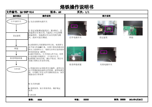
操作图示
7.附右图
核准:AAAA 审核:SSSSS 2014年4月26日制表:DDDDD 烙铁操作说明书
操作说明图片说明文件编号:QA-SOP-014
版本:A0页次:1/1焊接
打开电源开关设定湿度关闭电源 5.先关闭电源
6.烙铁保养,依日常保养表,维护规定处理。
打开电源开关1.先启动烙铁电源开关2.设定试验测试温度后,5分种后,且加温指示灯被点亮,当温度上升达到测试温度时,加温指示灯由全亮转为熄
灭,此时可进行测试.3.1将烙铁头刃面紧贴在焊点处。
电烙铁与水平面大约成60℃角。
以便于熔化的锡从烙铁头上流到焊点上。
烙铁头在焊点处停留的时间控制在2~3秒钟。
3.2抬开烙铁头。
左手仍持元件不动。
待焊点处的锡冷却凝固后,才可松开左手。
3.3用镊子转动引线,确认不松动,然后可用偏口钳剪去多余的引线。
4.焊接结束后必须检查有无漏焊、虚焊以及
由于焊锡流淌造成的元件短路。
虚焊较难发现,可用镊子夹住元件引脚轻轻拉动,如发现摇动应立即补焊
检查焊接质量设定温度焊接
检查焊接质量
关闭电源开关。

电烙铁使用指导书
电烙铁使用指导书
(理论方面)
一:新的电烙铁在初次使用时要注意以下几点:1,新烙铁头在烙铁通电后要用助焊剂(松香)涂在烙铁头上2,新电烙铁在初次使用时要先用焊锡不停地融化焊锡丝3,新烙铁芯在初次使用时会冒烟是正常情况,大约持续10秒钟左右,如果一直冒烟或者烟很浓,请立即关闭烙铁电源4,出现火花或者声响等异常情况应立即关闭其电源二:手拿电烙铁的正确使用方法是用右手的大拇指,食指和中指,用中指支撑电烙铁,拇指和食指固定电烙铁,使电烙铁在手伸直的情况下与手臂成大约30度
三:在焊接时要注意不要让烙铁头长时间和元器件接触,电烙铁头的温度很高很容易将元器件烫坏或烫伤,杜绝在使用过程中用电烙铁头做非焊接的工作例如,去烫化非焊锡的物品,当成镊子去分开物品等等
四:电烙铁在使用时要轻拿轻放,要有固定的烙铁支架,杜绝乱甩或动作过大的举动,坚决避免手拿电烙铁和别人开玩笑或者做一些非焊接的举动,较长时间不使用时应该关闭插座电源开关,拔掉电烙铁插座,如果是短时间不使用应该在电烙铁头上沾放一些焊锡,目的保护电烙铁头不被烧坏而减少使用寿命!
五:在任何非修理电烙铁的时候,都不应该用手去触摸电烙铁发热管和烙铁头!
六:确定电烙铁不使用而关闭电源前,应该将电烙铁头清理干净不要残留焊锡或者其他杂质,清理烙铁架残留物及清洁海棉不要留到下一次使用时再清洁
工程部于7月10日。

电烙铁作业指导书目录1 目的 (1)2 适用范围 (1)3 术语与定义 (1)4 职责和权限 (1)5 程序 (1)5.1注意事项 (1)5.1.1人身安全及防护 (1)5.1.2注意事项 (1)5.1.3 应用失准验证 (2)5.2使用方法 (2)5.2.1新烙铁在使用前的处理 (2)5.2.2 电烙铁的握法 (2)5.2.3 使用步骤 (3)5.2.4 焊接五步法 (3)5.2.5 结束使用步骤 (3)5.2.6 最适当工作温度 (4)5.3恢复与保养 (4)5.3.1 烙铁头保养 (4)5.3.2 烙铁头换新 (4)6 相关文件 (4)7 记录表样 (4)1 目的为了帮助员工安全、有效的使用恒温电烙铁进行生产作业,规范员工的操作步骤,增强员工对工具的保养及维护意识。
2 适用范围电气组研发人员、生产技术员等。
3 术语与定义3.1开关(1):开关电烙铁3.2旋钮(2):温度调节。
3.3烙铁柄(3):辅助焊接。
3.4烙铁头(4):加热熔化焊锡丝进行焊接。
4 职责和权限4.1质量部负责仪表发放、问题处理。
图3-14.2使用人员负责仪表日常维护,保养,使用。
5 程序5.1注意事项5.1.1人身安全及防护避免烙铁头烫伤自己及他人。
5.1.2注意事项5.1.2.1使用注意事项1)电烙铁通电后温度高达250摄氏度以上,不用时应放在烙铁架上,但较长时间不用时应切断电源,防止高温“烧死”烙铁头(被氧化)。
要防止电烙铁烫坏其他元器件,尤其是电源线,若其绝缘层被烙铁烧坏而不注意便容易引发安全事故。
2)不要把电烙铁猛力敲打,以免震断电烙铁内部电热丝或引线而产生故障。
3)电烙铁使用一段时间后,可能在烙铁头部留有锡垢,在烙铁加热的条件下,我们可以用湿布轻檫。
如有出现凹坑或氧化块,应用细纹锉刀修复或者直接更换烙铁头。
4)焊接过程中注意烙铁头不能触碰到其他元器件。
5.1.2.2焊接注意事项:1)烙铁头的温度要适当,不同温度的烙铁头放在松香块上,会产生不同的现象,一般来说,松香熔化较快又不冒烟时的温度较为适宜。
12345
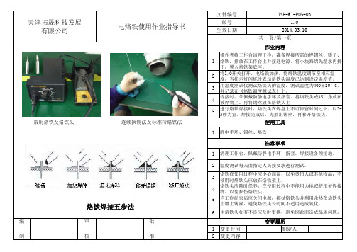
常用烙铁及烙铁头11
2
3
4561变更时间制定人2变更内容电烙铁使用作业指导书连续执锡法及标准持烙铁法
变更履历温度测试每天由指定人员按要求进行测试。
共一页/第一页
烙铁在使用过程中应小心高温,以免烫伤人或其他物品,不使用时烙铁头应放在烙铁架上。
天津拓晟科技发展有限公司注意事项
清理工作台,佩戴防静电手环、指套,焊接设备须接地。
文件编号版号2014.03.10
静电手环、锡丝、烙铁
将I/O开关打开,电烙铁加热,将烙铁温度调节至相应温度,当指示灯闪烁时表示烙铁头温度已达到设定温度值。
用温度测试仪测试烙铁头的温度,测试温度为400±20°C,并记录在《烙铁温度测试表》上。
焊接时,须佩戴防静电手环及指套。
将烙铁头成45°角放在被焊物上,再将锡丝放在烙铁头上审核编
制批准烙铁头应随时保养,在使用过程中不能用力挑或挤压被焊接
物,以免损伤烙铁头。
TSH-WI-P05-03
1.0
作业内容生效日期
当工作结束后应关闭电源,擦拭烙铁头并利用余热在烙铁头上镀上锡丝,避免烙铁头长时间不适用造成氧化。
烙铁焊接五步法
电烙铁头如有不良应及时更换,避免因此而造成品质问题。
操作者将工作台清理干净,准备焊接所需的焊锡丝、镊子、烙铁,摆放在工作台上并接通电源。
将小块海绵先湿水再挤干,置入烙铁架底座。
进行烙铁焊接时,烙铁头在焊盘上不可停留时间过长,以2-3秒为宜。
焊接完成后,先抽出锡丝,再移开烙铁头。
使用工具。

烙铁使用管理规范一、烙铁的使用说明:电烙铁的握法:手握、正握和笔握三种,一般在焊接电路板上元器件的握法采用笔握法——右手拇指与食指、中指呈三角方位夹电烙铁手柄(同拿笔的方法一样),左手食指和大拇指轻轻捏住锡丝,留出的锡丝头长度大约为4-5CM,太长不便控制,太短易烫伤手指。
二、烙铁头的保养:电烙铁通电使用过程中,烙铁头会产生一些氧化物,应将烙铁头在浸水的清洗海棉上轻擦几下再使用(所用的清洗海绵每半天需加水一次,由本拉侍应生负责加好。
)保持烙铁头干净(在清洗烙铁头时,绝对不允许将烙铁发热元件部分浸入水中);不允许在烙铁架或工作台上敲击烙铁,以免损坏烙铁嘴或烙铁内部结构。
烙铁在发热后处于待用状态时,烙铁头应有少量焊锡附于其上,以保护烙铁头,绝对不允许将发热的烙铁头浸入水中。
用完电烙铁后,应将其正确置于烙铁架上,不得随意放置于其他位置或致使烙铁头接触工作台面和其他物品。
在某一较长的时间内不使用电烙铁时,应将其电源线拔掉,以免发生意外。
三、烙铁的检测1、烙铁温度的检测:将烙铁温度测试议装上电池,开关打开,然后将烙铁头加上少许锡轻放于烙铁温度测试仪的感温线交叉点上。
显示屏上所显示的温度即烙铁镕锡时的温度。
(烙铁温度的检测频率为每天上午、下午、晚上加班前各测试一次。
)2、烙铁漏电的检测:在检测漏电时,烙铁须处于接通状态,将数字万用表电压打到交流档,用数字万用表的红表笔接烙铁头,黑表笔接地线。
万用表显示屏数值如在0.1Ω以内表示此烙铁不漏电,如数值在0.1Ω以上,表示此烙铁漏电。
需采取措施消除此现象或更换烙铁。
(烙铁漏电的检测频率为每天上午、下午、晚上加班前各测试一次。
)四、烙铁头的更新1、普通烙铁:烙铁头穿孔、氧化严重时需更换烙铁头,更换烙铁头时,用十字批轻轻拧下焊铁头护套处的螺钉,然后抽出烙铁头,再将新的烙铁头装入焊铁头护套处拧紧螺钉,最后测试其温度是否在工艺文件要求内2、恒温烙铁:需更换烙铁头时,先拧下固定焊铁头护套的螺帽,然后拧下塑胶套头,将坏的烙铁头取下,更换好新的烙铁头,然后拧上塑胶套头,套上焊换头护套,拧紧螺帽,最后还需校准温度。

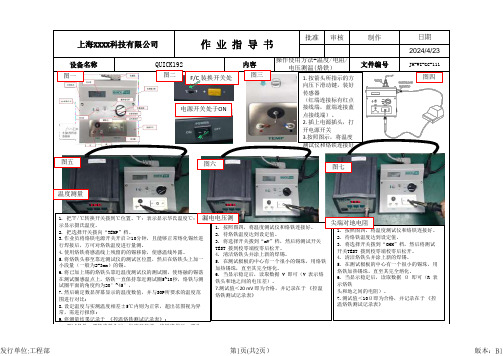
批准审核设备名称制作日期2024/4/23QUICK192内容操作使用方法-温度/电阻/电压测温(烙铁)文件编号JH-WI-GC-111 上海XXXX科技有限公司作 业 指 导 书 1. 按箭头所指示的方向压下滑动键,装好传感器(红端连接标有红点接线端,蓝端连接蓝点接线端)。
2. 插上电源插头,打开电源开关3.按照图示,将温度测试仪和烙铁连接好F/C 装换开关处电源开关处于ON 图一图二图三图五图六图七1. 把℉/℃转换开关拨到℃位置。
℉:表示显示华氏温度℃:表示显示摄氏温度。
2. 把选择开关拨向“TEMP”档。
3.作业员将烙铁电源开关开启≥10分钟,且能够正常熔化锡丝进行焊接后,方可对烙铁温度进行量测。
4.使用烙铁将感温线上残留的的锡移除,使感温线外露。
5.将烙铁头移至靠近测试仪的测试区位置,然后在烙铁头上加一小段量(一般为2-3mm )的锡。
6.将已加上锡的烙铁头靠近温度测试仪的测试圈,使熔融的锡落在测试圈感温点上,烙铁一直保持靠近测试圈5~10秒,烙铁与测试圈平面的角度约为20°~45°,7.然后确定数显屏幕显示的温度数值,并与SOP 所要求的温度范围进行对比;8.设定温度与实测温度相差±5℃内则为正常,超出范围视为异常,需进行报修;9.将测量结果记录于《控温烙铁测试记录表》;10.测试条件:更换烙铁头时,每班开线前,烙铁维修后,更改图四1. 按照图四,将温度测试仪和烙铁连接好。
2. 待烙铁温度达到设定值。
3. 将选择开关拨到“mV”档,然后将测试开关TEST 拨到校零端校零后松开。
4. 清洁烙铁头并涂上新的焊锡。
5. 在测试极板的中心有一个很小的锡珠,用烙铁加热锡珠,直至其完全熔化。
6. 当显示稳定后,读取数据V 即可(V 表示烙铁头和地之间的电压差)。
7.测试值<20 mV 即为合格,并记录在于《控温烙铁测试记录表》 1. 按照图四,将温度测试仪和烙铁连接好。
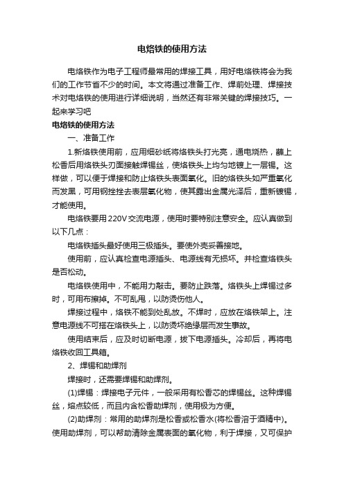
电烙铁的使用方法电烙铁作为电子工程师最常用的焊接工具,用好电烙铁将会为我们的工作节省不少的时间。
本文将通过准备工作、焊前处理、焊接技术对电烙铁的使用进行详细说明,当然还有非常关键的焊接技巧。
一起来学习吧电烙铁的使用方法一、准备工作1.新烙铁使用前,应用细砂纸将烙铁头打光亮,通电烧热,蘸上松香后用烙铁头刃面接触焊锡丝,使烙铁头上均匀地镀上一层锡。
这样做,可以便于焊接和防止烙铁头表面氧化。
旧的烙铁头如严重氧化而发黑,可用钢挫挫去表层氧化物,使其露出金属光泽后,重新镀锡,才能使用。
电烙铁要用220V交流电源,使用时要特别注意安全。
应认真做到以下几点:电烙铁插头最好使用三极插头。
要使外壳妥善接地。
使用前,应认真检查电源插头、电源线有无损坏。
并检查烙铁头是否松动。
电烙铁使用中,不能用力敲击。
要防止跌落。
烙铁头上焊锡过多时,可用布擦掉。
不可乱甩,以防烫伤他人。
焊接过程中,烙铁不能到处乱放。
不焊时,应放在烙铁架上。
注意电源线不可搭在烙铁头上,以防烫坏绝缘层而发生事故。
使用结束后,应及时切断电源,拔下电源插头。
冷却后,再将电烙铁收回工具箱。
2、焊锡和助焊剂焊接时,还需要焊锡和助焊剂。
(1)焊锡:焊接电子元件,一般采用有松香芯的焊锡丝。
这种焊锡丝,熔点较低,而且内含松香助焊剂,使用极为方便。
(2)助焊剂:常用的助焊剂是松香或松香水(将松香溶于酒精中)。
使用助焊剂,可以帮助清除金属表面的氧化物,利于焊接,又可保护烙铁头。
焊接较大元件或导线时,也可采用焊锡膏。
但它有一定腐蚀性,焊接后应及时清除残留物。
3、辅助工具为了方便焊接操作常采用尖嘴钳、偏口钳、镊子和小刀等做为辅助工具。
应学会正确使用这些工具。
尖嘴钳偏口钳镊子小刀二、焊前处理焊接前,应对元件引脚或电路板的焊接部位进行焊前处理。
1、清除焊接部位的氧化层可用断锯条制成小刀。
刮去金属引线表面的氧化层,使引脚露出金属光泽。
印刷电路板可用细纱纸将铜箔打光后,涂上一层松香酒精溶液。
电动烙铁使用指南电动烙铁是一种用于焊接和展示创造力的工具。
它可以帮助您完成各种电子零件的焊接工作,并且非常适合DIY爱好者和专业工程师。
本篇文章将为您提供电动烙铁使用的详细指南,帮助您掌握正确的使用方法和技巧。
1. 准备工作在使用电动烙铁之前,确保您已经做好了以下准备工作:- 确认您的工作区域清洁整洁,远离易燃物和易燃气体。
- 检查电动烙铁的插头和电源线是否完好无损,并确保电源线的接地良好。
- 确保烙铁头部附近没有任何杂质或脏污,以免影响焊接效果。
2. 加热烙铁在使用电动烙铁之前,您需要将其加热至适当的工作温度。
请按照以下步骤进行操作:- 插入电动烙铁的插头到电源插座中,并打开电源开关。
- 调节烙铁温控按钮或旋钮至适当工作温度。
不同的焊接任务需要不同的温度,请参考所使用焊锡的说明书或相关资料。
- 等待一段时间,直到烙铁头部达到设定温度。
通常,烙铁头部上的指示灯会显示出它是否已经加热至工作温度。
3. 准备焊锡和焊接表面在焊接之前,您需要准备好焊锡和焊接表面:- 确保焊锡的质量良好,并选择适合您的焊接任务的合适焊锡规格。
- 准备您需要焊接的表面,并确保它们干净、光滑,并且没有杂质或脏污。
4. 进行焊接现在,您可以开始进行焊接操作了。
请按照以下步骤进行操作:- 将电动烙铁头部轻轻触碰焊锡,让一小部分焊锡附着在烙铁头部。
- 将焊锡均匀地涂抹在需要焊接的表面上,确保焊锡能够充分涂覆焊接区域。
- 拿起焊锡并将其放置在焊接区域,然后轻轻按下并停留片刻,直到焊锡完全熔化和润湿焊接区域。
- 当焊锡已经润湿焊接区域时,可以将焊锡和烙铁头部从焊接区域上移开。
5. 完成焊接任务完成焊接后,您需要进行一些必要的操作以确保焊接任务的质量和持久性:- 如果焊接区域超过了所需的焊锡量,使用焊吸器或吸锡线将多余的焊锡吸取。
- 使用同轴电缆剥线钳或其他适当工具修剪和整理焊接区域的线头。
- 检查焊接区域的质量,并确保焊接的连接牢固可靠。
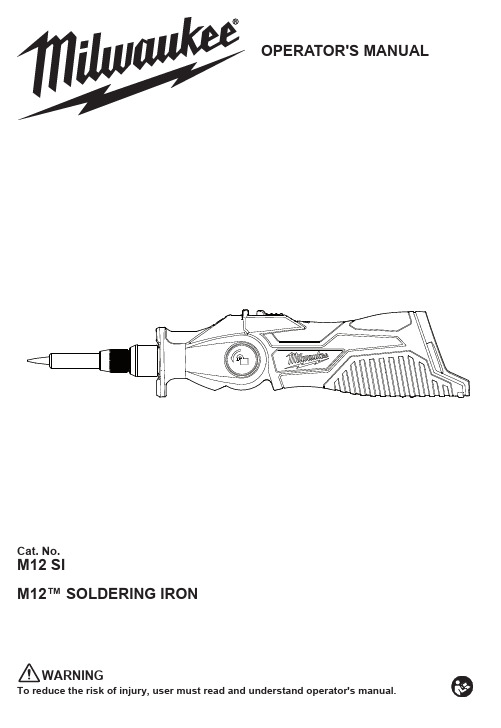
Cat. No.M12 SIM12™ SOLDERING IRONOPERATOR'S MANUALTo reduce the risk of injury, user must read and understand operator's manual.WARNINGtions provided with this power tool. Failure to follow all instructions listed below may result in electric shock, and/or serious injury. Save all warnings and in-structions for future reference. The term "power tool" in the warnings refers to your mains-operated (corded) power tool or battery-operated (cordless) power tool.WORK AREA SAFETY•K eep work area clean and well lit. Cluttered or dark areas invite accidents.•D o not operate power tools in explosive atmo-liquids, gases or dust. Power tools create sparks which may ignite the dust or fumes.•K eep children and bystanders away while operating a power tool. Distractions can cause you to lose control.ELECTRICAL SAFETY•PERSONAL SAFETY•S tay alert, watch what you are doing and use common sense when operating a power tool. Do not use a power tool while you are tired or underA moment of inattention while operating power tools may result in serious personal injury.•U se personal protective equipment. Always wear eye protection. Protective equipment such as a dust mask, non-skid safety shoes, hard hat or hearing protection used for appropriate conditions will reduce personal injuries.•P revent unintentional starting. Ensure the switch is in the off-position before connecting to power source and/or battery pack, picking up or carrying the tool.switch or energizing power tools that have the switch on invites accidents.•D o not overreach. Keep proper footing and balance at all times. This enables better control of the power tool in unexpected situations.•D ress properly. Do not wear loose clothing or jewelry. Keep your hair and clothing away from moving parts. Loose clothes, jewelry or long hair can be caught in moving parts.•D o not let familiarity gained from frequent use of tools allow you to become complacent and ignore tool safety principles. A careless action can cause severe injury within a fraction of a second.POWER TOOL USE AND CARE•D o not force the power tool. Use the correct power tool for your application. The correct power tool will do the job better and safer at the rate for which it was designed.•D o not use the power tool if the switch does not turn it on and off. Any power tool that cannot be controlled with the switch is dangerous and must be repaired.•D isconnect the plug from the power source and/ or remove the battery pack, if detachable, from the power tool before making any adjustments, changing accessories, or storing power tools. Such preventive safety measures reduce the risk of starting the power tool accidentally.•S tore idle power tools out of the reach of children and do not allow persons unfamiliar with the power tool or these instructions to operate the power tool. Power.s r e s ud e n i a r t n u f os d n a he h t n i s u o r e g n a de r as l o o t•M aintain power tools and accessories. Check for misalignment or binding of moving parts, breakage of parts and any other condition that may affect the power tool’s operation. If damaged, have the power tool repaired before use. Many ac-cidents are caused by poorly maintained power tools.•U se the power tool, accessories and tool bits etc. in accordance with these instructions, taking into account the working conditions and the work to be performed. Use of the power tool for operations different from those intended could result in a hazardous situation.•K eep handles and grasping surfaces dry, clean and free from oil and grease. Slippery handles and grasping surfaces do not allow for safe handling andmanufacturer. A charger that is suitable for one type of batteryanother battery pack.•battery packs. Use of any other battery packs may•W hen battery pack is not in use, keep it away from other metal objects, like paper clips, coins, keys, nails, screws or other small metal objects, that can make a connection from one terminal to another. Shorting •U nder abusive conditions, liquid may be ejected from the battery; avoid contact. If contact acci-eyes, additionally seek medical help. Liquid ejected from the battery may cause irritation or burns.•D o not use a battery pack or tool that is damaged orrisk of injury.••Follow all charging instructions and do not chargewill ensure that the safety of the power tool is maintained.•N ever service damaged battery packs. Service of battery packs should only be performed bythe manufacturer or authorized service providers.•Do not modify or attempt to repair the tool or the battery pack except as indicated in the instructionspack. Tool could tip resulting in contact betweentool on its side when not in use.•K eep hands andburns can occur if skin contacts tip.•R emove battery before storing. Such preventive safety measures reduce the risk of starting the power tool accidentally.Indoor use. Do not expose power tools to rainor wet conditions. Water entering a power toolwill increase the risk of electric shock.Do not expose a battery pack or tool to fire orexcessive temperature. Exposure to fire ortemperature above 130°C (265°F) may causeexplosion.23• W ork in well ventilated areas. Soldering can produce fumes and smoke.• U se personal protective equipment when usingFollowall manufacturer instructions.•Ma intain labels and nameplates. Thesecarry important information. If unreadable or missing, contact ® service facility for a replacement.grinding, drilling, and other contains chemicals known to cause cancer, birth defects or other reproductive harm. Some examples of these chemicals are:• l ead from lead-based paint • c rystalline silica from bricks and cement and other masonry products, and • a rsenic and chromium from chemically-treated lumber. Your risk from these exposures varies, depending on how often you do this type of work. To reduce your exposure to these chemicals: work in a well ventilated area, and work with approved safety equipment, such as those dust masks that are specially designed toSPECIFICATIONSCat. No. .......................................................M12 SIVolts..............................................................12 DC Battery Type .................................................M12™Charger Type................................................M12™Average Heater Power (Max) .........................90 W Set Tip Temperature .........................399o C (750o F)Replacement Point Tip .........................49-80-0400Replacement Chisel Tip........................49-80-0401Recommended Ambient Operating Temperature ....................0o C to 52o CFUNCTIONAL DESCRIPTION1. Rotating head2. Rotation button3. Slide switch4. Fuel guage5. Temp indicator6. Finger guard7. Nut8. Barrel9. Soldering tip 10. L EDSYMBOLOGYVolts Direct CurrentCAUTION! Tip is hot. Avoid contact.Removing/Inserting the BatteryTo remove the battery, push in the release buttons To insert the battery, slide the pack into the bodyTip burns could occur if skin contacts a hot tip.To replace the tip:1. After the tip has cooled and the tip temp indicator is off, remove the battery pack.2. Unscrew the nut and remove the nut and barrel.3. Remove the tip and replace.4. Reinstall the nut and barrel. Tighten the nut securely.Rotating the HeadTo rotate the head at any time,press in the rotation button and rotate the head to the desired angle.OPERATIONsafety goggles or glasses with side shields. -ous burns could occur if skin contacts a hot tip.Soldering1. Prepare the workpiece.2. Rotate head to desired angle.3. Press the slide switch forward to turn on the tool.4. To lock-on the switch press down on the front of the switch.5. Allow the tool to come to full temperature. Temp Indicator: Blinking Green → HeatingSolid Green →6. Solder according to material requirements.7. When done, turn off tool by releasing switch or, if locked-on, pressing back of switch and releasing.Solder melt temp(204°C-399°C (400-750°F))This appliance is not intended for use by persons (including children) with reduced physical, sensory orknowledge, unless they have been given supervision or instruction concerning use of the appliance by aperson responsible for their safety. Children shouldbe supervised to ensure that they do not play with theappliance.•36101287954pack or charger in fluid or allow a fluid to flow inside them. Corrosive or conductive fluids, such asseawater, certain industrial chemicals, and bleachor bleach-containing products, etc., can cause ashort circuit.Regulatory Compliance Mark (RCM). Product meets applicable regulatory requirements.4MAINTENANCEbattery pack from the charger or tool before performing any maintenance. Never disassemble the tool, battery pack or charger. Contact a MILWAUKEE ® service facility for ALL repairs.Maintaining Toolpack or charger in liquid or CleaningWhile still hot, clean the tip with a wet sponge or brass cleaning wire. Tip-tinner/cleaner can also be used. WARNING! Avoid contact, tip is hot and could cause serious burns.Keep handles clean, dry and free of oil or grease. Use only mild soap and a damp cloth to clean, since certain cleaning agents and solvents are harmful to plastics and other insulated parts. Some of these include gasoline, turpentine, lacquer thinner, paint thinner, chlorinated cleaning solvents, ammonia and household detergents containing ammonia. NeverRepairsFor repairs, return the tool, battery pack and charger to the nearest service center.ACCESSORIESallow a liquid to flow inside them.For a complete listing of accessories, go online to .au / or contact a distributor.Keep your tool, battery pack and charger in good repair by adopting a regular maintenance program. Inspect your tool for issues such as undue noise, misalignment or binding of moving parts, breakage of parts, or any other condition that may affect the tool operation. Return the tool, battery pack, and charger to a MILWAUKEE ® service facility for repair. After six months to one year, depending on use, return the tool, battery pack and charger to a MILWAUKEE ® service facility for inspection.If the tool does not start or operate at full power with a fully charged battery pack, clean the contacts onthe battery pack. If the tool still does not work properly, return the tool, charger and battery pack, to a MILWAUKEE ® service facility for repairs.For a list of MILWAUKEE ® dealers, guarantee or service agents please contact MILWAUKEE ®Customer Service or visit our website.(Australia Toll Free Telephone Number 1300 645 928)(New Zealand Toll Free Telephone Number 0800 279 624)or visit .au / .MILWAUKEE prides itself in producing a premium quality product that is Nothing But Heavy Duty .Your satisfaction with our products is very important to us! If you encounter any problems with the operation of this tool, please contact your authorised MILWAUKEE ® dealer.Please refer to Australian and New Zealand warranty supplied with tool. This warranty applies only to product sold in Australia and New Zealand.Milwaukee Electric Tool Corporation13135 West Lisbon Road, Brookfield, Wisconsin U.S.A. 53005Milwaukee Tool (Australia)21 Kelletts Road, Rowville, VIC 3178Melbourne, AustraliaMilwaukee Tool (New Zealand)2 Landing Drive, Mangere Auckland, 2022, New ZealandDesigned by Milwaukee Electric Tool Corp.Professionally Made in China for Milwaukee Tool (Australia) / Milwaukee Tool (New Zealand)Printed in China8. While still hot, clean the tip with a wet sponge or brass cleaning wire. WARNING! Avoid contact, tip is hot and could cause serious burns.9. Place tool on its side with the tip away from any contact until it has coolded.Temp Indicator:Solid Red → CoolingWARNING! Do not touch tip or remove battery pack until Temp Indicator turns off, indicating the。
恒温烙铁操作指导书1. 引言1.1 目的和范围本文档旨在提供关于恒温烙铁的详细操作指南,以确保用户正确、安全地使用该设备。
2. 设备概述恒温烙铁是一种具有稳定工作温度并可调节加热功率的电子焊接工具。
它通常由手柄、发射器和附件组成。
3. 安全注意事项在使用恒温烙铁之前,请务必阅读以下安全注意事项:3.1 确保插头与电源匹配,并将其牢固连接;3.2 使用合适大小且不易打滑的支架来放置正在加燥或冷却中的设备;...4 . 准备步骤此章节描述了准备开始使用恒定性钎焊机所需执行的所有任务。
这些包括但不限于:检查材料清单,确认环境条件等。
5 . 操作流程进行实际操作时应遵循下列步骤:a) 打开主电源开关;b) 谨慎选择需要进行焊接/融化处理的物体 ;c) 将烙铁头放置在需要加工的物体上 ;d) 等待一段时间,直到焊接完成;e ) 关闭主电源开关。
6 . 温度调节为了获得最佳性能和结果,请根据以下步骤正确地调整恒温烙铁的温度:a)打开设备并等待预定时间以使其达到稳态;b)使用控制按钮或旋钮选择所需的目标温度值;c)确认显示屏上显示出您设置的实际当前温度。
7. 维护与保养正确维护和保养是确保恒定性钎焊机正常运行和延长寿命至关重要。
本章介绍了必须执行的例行任务、清洗指南及存储建议。
8. 故障排除如果发现任何故障情况,请参考此章节中出来的可能原因,并采取相应纠正措施。
如如果问题无法解决,请联系售后服务团队进行进一步支持。
9. 附件本文档涉及以下附件:(列出所有相关文件名称)10. 法律名词及注释- 操作者: 使用该设备进行操作或管理活动的个人或实体。
- 烙铁头: 设备上用于加热和焊接物品的部件。

恒温电烙铁操作指导书(ISO9001-2015)一、操作步骤1.1焊接前准备1.1.1将烙铁插头插入插座,打开烙铁开关,按要求设定温度;1.1.2温度检查使用校验合格专用烙铁温度检查设备,接地检查使用校验合格的万用表进行测量检测;1.1.3把清洁海棉浸湿水,再挤干多余水分(手捏不再出水为佳);如果使用非湿润的清洁海棉,会使烙铁头受损而导致不上锡时间久了受到损坏;1.1.4烙铁使用前先按照指导书上的标准调节好温度,还应作温度测试(温度测试以温度计测试为准)及进行接地测试验证有无漏电超标;1.2焊接工作1.1.1当烙铁温度达到设定值后,此时方可进行焊接作业;1.1.2烙铁五分钟内不使用或下班时,需将烙铁温度调至250℃,并在烙铁头上加一层新的焊锡进行保护,以免烙铁咀氧化,或者将其关掉电源。
二、注意事项2.1尽量使用低温焊接,如果烙铁头温度超过470℃,它的氧化速度是380℃的两倍;2.2不用烙铁时,不可将烙铁长时间处于高温状态,否则会加速氧化物产生;2.3焊接时勿施压过大,否则会使烙铁头受损变形;2.4禁止在台面敲打烙铁或者进行与硬物碰撞,烙铁必须有接地保护;2.5经常保持烙铁咀上锡,防止氧化;2.6海棉未加湿禁止使用;2.7勿使用烙铁咀有损坏之烙铁,以免焊接时候勾挂坏元器件;2.8如果烙铁咀粘上有助焊剂等附在上面的异物导致颜色变黄,可以用少量酒精进行擦拭干净后再使用。
三、设备保养3.1先把烙铁温度调至250℃,用清洁海棉清洁焊咀,然后上锡,不断重复动作,直至把烙铁头氧化物清理为止;3.2对所使用的烙铁,每周或者需要必须清理时候拆开一次烙铁头清除氧化物(恒温烙铁头内部,镙帽,镙纹内及放置烙铁座内之污物也需清理),防止烙铁头受损而降低温度传导;3.3烙铁手柄与焊台之插头尽可能减少插接次数,并且用力不宜过大,以免导致相互碰撞之后造成损坏。


jbc烙铁使用指南
JBC烙铁是一种高端的电子焊接工具,具有快速加热、高精度温度控制、易于更换烙铁头等优点。
以下是JBC烙铁使用指南:
1. 使用前先清洁烙铁头:使用钢丝球或橡皮擦清洁烙铁头,确保表面干净无杂质。
2. 连接烙铁和电源:将烙铁插入电源插座,等待几秒钟,烙铁就开始加热了。
3. 调节温度:使用JBC烙铁可以非常精准地调节温度。
在烙铁加热之后,使用控制按钮调节温度,可以根据需要将温度调节到合适的范围内。
4. 更换烙铁头:如果需要更换烙铁头,先将烙铁头从烙铁上拆下来,然后安装新的烙铁头。
注意,在更换烙铁头时,必须等到烙铁冷却到室温。
5. 使用烙铁:使用烙铁时,将烙铁头置于焊点上,轻轻按下烙铁头,等待几秒钟,然后轻轻拨动烙铁头,直到焊点成功焊接。
6. 关闭烙铁:当不再需要使用烙铁时,将烙铁头放回支架上,并将烙铁头温度调节至最低。
此时烙铁会自动关闭。