CMA-8-2002中文资料
- 格式:pdf
- 大小:889.76 KB
- 文档页数:2

十大公司箱位共5478992TEU占世界集装箱船队总箱位9135749TEU的60.0%。
注册地承运人中文英文缩写箱位1丹麦AP摩勒/马士基MAERSK1165272TEU占18.2%2瑞士地中海船运MSC784248TEU占8.6%3法国达飞CMA CGM547954TEU占5.6%4中国台湾长荣EVERGREEN477911TEU占5.2%5德国赫伯罗特Hapag-Lloyd412344TEU占4.5%6中国中海集运CSCL346493TEU占3.8%7美国美国总统轮船APL331437TEU占3.6%8韩国韩进海运/胜利Hanjin328794TEU占3.6%9中国中远集运COSCO322326TEU占3.5%10日本日本邮船NYK302213TEU占3.3%A.P. 穆勒公司介绍/appmanager/A.P. 穆勒集团公司始建于1904年,创始人是当时年仅28岁的阿诺得·穆勒和他的父亲马士基·一条载重仅2,200吨的二手汽轮起家。
由于经营有方,业务发展很快,目前是世界上最大的船该司总部设在丹麦哥本哈根市的埃斯普拉纳登。
该司在世界100多个国家设有325家分支机构名雇员。
由200余艘船只组成的A.P.穆勒公司船队总吨位约达到10,000,000吨,包括集装箱船、油轮、船、供应船和钻井设备。
除了海运业,A.P. 穆勒公司还经营物流、石油和天然气的勘探开发空运输业、工业、零售业以及信息产业。
该公司是一间综合性经营的大型跨国集团公司,集公司和集装箱码头,在丹麦商界和政界均有较大的影响力。
早在1928年,A.P.穆勒先生就以马士基船运公司开始提供货物班轮服务,将美国及远东和欧在兼并了美国的海陆(Sealand)公司国际海运业务后,该集团拥有250多条集装箱船和70万个集范围内为用户提供了可靠和综合性的服务保证。
除了有卡车、火车和飞机以外,马士基船运己的供料船,以提供独特的门到门服务。

Combined Certificate of Value and Origin(CCVO,估价和原产地联合证明书)名称为“估价和原产地联合证明书”的发票在习惯上都视作: 海关发票OF:海运费THC:码头操作费DOC:文件费ORC:码头费BAF 燃油附加费CAF:O/FX6.2%AMS:反恐费TRU:拖车费SQ:卫检费D/O:换单费DEM:滞箱费CUS:报关费(1)ORC (Origen Recevie Charges) 本地收货费用(广东省收取)欧美,北非(2)THC (Terminal Handling Charges) 码头操作费(香港收取)去东南亚,西非天津港按人民币收取小柜370,大柜560。
南方深圳一般按美金(3)BAF (Bunker Adjustment Factor) 燃油附加费(4)CAF (Currency Adjustment Factor) 货币贬值附加费(5)YAS (Yard Surcharges)码头附加费(6)EPS (Equipment Position Peak) 设备位置附加费(7)DDC (Destination Delivery Charges) 目的港交货费(8)PSS (Peak Season Surcharges) 旺季附加费(9)PCS (Port Congestion Surcharge) 港口拥挤附加费(10)DOC (document.nbspcharges) 文件费(11)O/F (Ocean Freight) 海运费(12)B/L (Bill of Lading) 海运提单(13)MB/L(Master Bill of Lading) 船东单(或OCEAN BILL OF LADING)(14)MTD (Multimodal Transport document.多式联运单据(15)L/C (Letter of Credit) 信用证(16)C/O (Certificate of Origin) 产地证(17)S/C (Sales Confirmation)销售确认书(Sales Contract) 销售合同(18)S/O (Shipping Order)装货指示书(19)W/T (Weight Ton)重量吨(即货物收费以重量计费)(20)M/T (Measurement Ton)尺码吨(即货物收费以尺码计费)(21)W/M(Weight or Measurement ton)即以重量吨或者尺码吨中从高收费(22)CY (Container Yard) 集装箱(货柜)堆场(23)FCL (Full Container Load) 整箱货(24)LCL (Less than Container Load) 拼箱货(散货)(25)CFS (Container Freight Station) 集装箱货运站(26)TEU (Twenty-feet Equivalent Units) 20英尺换算单位(用来计算货柜量的多少)(27)A/W (All Water)全水路(主要指由美国西岸中转至东岸或内陆点的货物的运输方式)(28)MLB(Mini Land Bridge)小陆桥(主要指由美国西岸中转至东岸或内陆点的货物的运输方式)(29)NVOCC(Non-Vessel Operating Common Carrier) 无船承运人公司简称缩写澳大利亚国家航运公司澳国航运ANL美国总统轮船私人有限公司美国总统APL邦拿美船务有限公司邦拿美BNML波罗的海航运公司波罗的海BOL中波轮船股份公司中波C-P南美邮船公司南美邮船CLAN S.A.南美智利国家航运公司智利航运CCNI中日国际轮渡有限公司中日轮渡CHINJIF天敬海运天敬海运CK法国达飞轮船公司达飞轮船CMA京汉海运有限公司京汉海运CO-HEUNG中国远洋集装箱运输有限公司中远集运COSCO 朝阳商船有限公司朝阳商船CHOYANG达贸国际轮船公司达贸国际DELIMAS德国胜利航运公司德国胜利SENATOR埃及国际轮船公司埃及船务EIL长荣海运股份有限公司长荣海运EVERGREEN远东轮船公司远东轮船FESCO金发船务有限公司金发船务GFNG浩洲船务公司浩洲船务HCSC韩进海运有限公司韩进海运HANJIN香港航运有限公司香港海运HKMSH香港明华船务有限公司香港明华HKMW赫伯罗特船务有限公司赫伯罗特HAPPAG-LLOYD 现代商船有限公司现代商船HYUNDAI上海海隆轮船有限公司海隆轮船HNT金华航运有限公司金华航运JH川崎汽船株式会社川崎汽船K LINE高丽海运株氏会社高丽海运KMTC七星轮船有限公司七星轮船SSCL上海育海航运公司育海航运SYH上海中福轮船公司中福轮船SZFSC墨西哥航运有限公司墨西哥航运TMM上海天海货运有限公司天海货运TMSC东航船务有限公司东航船务TOHO宁波泛洋船务有限公司宁波泛洋TOS阿拉伯联合国家轮船公司阿拉伯轮船UASC立荣海运股份有限公司立荣海运UNIGLORY环球船务有限公司环球船务UNIWD万海航运股份有限公司万海航运WANHAI伟航船务有限公司伟航船务WH阳明海运股份有限公司阳明海运YANGMING以星轮船船务有限公司以星轮船ZIM浙江远洋运输公司浙江远洋ZOSCO联丰船务有限公司联丰船务LIFEN意大利邮船公司意大利邮船LT马来西亚国际航运有限公司马来西亚航运MISC商船三井有限公司商船三井MOL地中海航运公司地中海航运MSC马士基海陆有限公司马士基海陆MAERSK SEALAND 民生神原海运有限公司民生神原MSKM太古船务代理有限公司太古船代NGPL铁行渣华船务有限公司铁行渣华P&O NEDLLOYD新加坡海皇轮船有限公司海皇轮船NOL北欧亚航运有限公司北欧亚航运NORASIA宁波远洋运输公司宁波远洋NOSCO南星海运株式会社南星海运NS沙特阿拉伯国家航运公司沙特航运NSCSA日本邮船有限公司日本邮船NYK东方海外货柜航运有限公司东方海外OOCL萨姆达拉船务有限公司萨姆达拉SAMUDERA太平船务有限公司太平船务PIL泛洋商船株式会社泛洋商船POBU瑞克麦斯轮船公司瑞克麦斯RICKMERS美商海陆联运(中国)有限公司美商海陆S/L南非国家轮船有限公司南非轮船SAF东映海运有限公司东映海运SBL上海国际轮渡有限公司国际轮渡SFCO中海发展股份有限公司中海发展CSD长锦有限公司长锦公司SINKO上海市锦江航运有限公司锦江船代JINJIANG中外运(集团)总公司中外运SINOTRANS志晓船务有限公司志晓船务SSC代码公司中文名称公司英文名称ABC ABC货柜航运公司A.B.C CONTAINTER LINEACBL 美国商业驳船航运公司American Commercial BargeLine companyACGR 冠航集团Ace GroupACL 大西洋集装箱航运公司Atlantic Contaier LineACT 联合集装箱运输公司(英)Associated Container TransportationAECS 澳大利亚欧洲集装箱服务公司Australia Europe Container ServiceAEL 美欧轮船公司American-European LinesAEXL 美国出口航运公司American Export LinesAFS 亚运香港船务有限公司Asia Fortune(HK) Shipping ltd. AFSC 非洲轮船公司(英)African Steamship Co.AJCL 澳大利亚-日本集装箱航运公司Australia Japan Container LineAMCL 美国商业轮船公司American commercial Lines, IncorporatedAMISCL 美国伊拉克轮船公司American Iraqi Shipping Company, Ltd.AML 美国邮船公司American Mail LineAMPTC 阿拉伯海上石油运输公司Arab Maritime Petroleum transport Co.AND 亚得利亚航运公司(意大利)Adriatica Di Navigazione SpaANL 澳州国家航运Austrilian National LineANST 阿里亚国家航运公司(伊朗)Arya National Shipping LinesAOR 挪亚AORASIAAPL 美国总统轮船公司American Predsident lines Ltd.ASC 阿拉斯加轮船公司(美)Alaska Steamship Company ASS 阿莱德ASTA 朝日油轮公司(日)Asahe-TankerATL 亚洲货运中心Asia Terminal LimitedATTL 大西洋轮船运输公司Atlantic Transport lineAWP 澳大利亚西太平洋轮船公司Australia West Pasific LineBEN 边行集装箱运输公司(英国)Ben Line Containers Ltd. BK 刚兴船务有限公司Kong Hing Agemcy LtdBOL 波罗地海远东航运公司Baltic Orient LineBONA 邦拿美Bonami LineBRN 保加利亚河运公司Bulgarian River NavigationBSC 孟加拉国海运公司Bangladesh Shipping Co.BSP 巴尔的摩定期轮船公司(美)Baltimore Steam Packet BTC 伯利恒运输公司(美)Bethlehemm Transportation Co.找到一篇文章供参考:THC在中国的现状及中国货主依法维权的情况早在1997年,一些班轮公司就在中国的广东、广西、云南和海南地区向外贸货主收取ORC(Origin Receiving Charge始发地收货费)。
红麻全杆化机浆的制备周晓强;牛梅红;李娜;孙衍宁【摘要】用红麻制取化学浆可生产中高档纸或纸板,但化学浆得率低,并且废液需要处理.对红麻全秆化学机械浆进行了研究,以提高红麻原料的利用率,减少废液污染负荷.采用NaOH作为红麻生产化机浆的化学处理剂,通过正交试验确定了红麻全杆NaOH化学机械浆制浆的适宜条件:温度80℃,处理时间40 min,NaOH用量8%.经过机械处理后成浆的得率为84%,紧度为0.609 g/cm3,撕裂指数为13.84 mN.m2/g,环压指数为0.13N.m/g,打浆度为42.SR,耐折度为253.5次,成浆可以抄造瓦楞原纸.%The intermediate-high rail paper and paperboard can be produced by kenaf chemical pulp,but the yield is low and the waste liquid must be treated.So the chemical-mechanical pulping is adopted to produce corrugated paper to improve the utilization ratio and decrease contaminate pressure.With a series of orthogonal experiment,the condition for kenaf NaOH chemi-mechanical pulp are confirmed that the temperature is 80 C,medicine cook time is 40 min,NaOH charge is 8%.The tightness 0.609 g/cma,tearability is 13.84 mN ~ m2/g,ring-shaped pressure is 0.13 N · m/g,beating degree is 42°SR,the yield is 84%,folding endurance is 253.5 degrees and the properties of sheet attained in this excellent condition are ideal.【期刊名称】《大连工业大学学报》【年(卷),期】2013(032)004【总页数】3页(P252-254)【关键词】红麻;化机浆;瓦楞原纸【作者】周晓强;牛梅红;李娜;孙衍宁【作者单位】大连工业大学轻工与化学工程学院,辽宁大连 116034;大连工业大学轻工与化学工程学院,辽宁大连 116034;大连工业大学轻工与化学工程学院,辽宁大连 116034;大连工业大学轻工与化学工程学院,辽宁大连 116034【正文语种】中文【中图分类】TS7430 引言原料短缺是世界造纸工业面临的三大问题之一,该问题在我国造纸工业显得尤为突出。

中国合格评定国家认可委员会:中国合格评定国家认可委员会(英文名称为:China National Accreditation Service for Conformity Assessment 英文缩写为:CNAS),是根据《中华人民共和国认证认可条例》的规定,由国家认证认可监督管理委员会批准设立并授权的国家认可机构,统一负责对认证机构、实验室和检验机构等相关机构的认可工作。
CNAS由原中国认证机构国家认可委员会(英文简称为CNAB)和原中国实验室国家认可委员会(英文简称为CNAL)合并而成。
CNAS通过评价、监督合格评定机构(如认证机构、实验室、检查机构)的管理和活动,确认其是否有能力开展相应的合格评定活动(如认证、检测和校准、检查等)、确认其合格评定活动的权威性,发挥认可约束作用。
历史沿革:中国合格评定国家认可委员会于2006年3月31日正式成立,是在原中国认证机构国家认可委员会(CNAB)和原中国实验室国家认可委员会(CNAL)基础上整合而成的。
中国认证机构国家认可委员会(CNAB)是经中国国家认证认可监督管理委员会依法授权设立的国家认可机构,负责对从事各类管理体系认证和产品认证的认证机构进行认证能力的资格认可。
成立于2002年7月,是由原中国质量体系认证机构国家认可委员会(CNACR)、原中国产品认证机构国家认可委员会(CNACP)、原中国国家进出口企业认证机构认可委员会(CNAB)和原中国环境管理体系认证机构认可委员会(CACEB)整合而成。
2004年4月,根据国家认证认可监督管理委员会与有关部门协调的意见和决定,原全国职业健康安全管理体系认证机构认可委员会(CNASC)、原有机产品认可委员会分别将职业健康安全管理体系及有机产品认证认可工作移交CNAB,进一步促进了统一的认证机构认可制度的深度融合。
中国实验室国家认可委员会(CNAL)是经中国国家认证认可监督管理委员会批准设立并授权,统一负责对认证机构、实验室和检验机构认可及相关工作的国家认可机构。


世界各大船公司背景资料--1、Mearsk:总部在哥本哈根,是一6层小楼,有电梯,但很少人坐电梯,因为大老板每天爬楼梯到自己六楼办公室,所以没人敢坐,都爬楼。
其上缴税收占到丹麦政府收入的40%,Mearsk对新员工要求很高,分为employee和trainee,前者是一般雇员,后者要到丹麦总部经过几个月的集中培训,然后派到世界各地任职,最后不管男女,上船锻炼半年,再委以重任。
2、3、2、MSC:在瑞士注册。
MSC的船名以*女的名字居多,如洛丽塔、法米娅之类。
MSC从不和其他公司融舱,船都很大,运价低,也很少租箱子,全部是自有箱。
4、5、3、长荣海运:张荣发40年心血的结晶,长荣是股份公司,张荣发控股,但是还有他人股份,当年航运市场最低迷的时候,张荣发注册了立荣,。
但后来市场越来越好,长荣越来越好,于是长荣收購立荣,后来为了经营两岸直航,继续收购意邮,以欧洲公司的名义作直航。
去年又成立HASUMARINE,因为2006年长荣运力将增长40%,要分散风险。
6、7、4、再说中远。
(cosco)是中国的第二海军,享受国家最最最优惠的航运政策。
我们接触比较多的是中远集运,这两年航运市场市场好,但是中集没赚道什么钱,主要原因是中集运价体制太乱,特价申请满天飞,差不多每张申请都有背景,主管人员又不得不批。
作为老牌国企,中远还是当代中国航运界的黄埔军校!8、9、5、铁行渣华:P&O和Nedlloyd原是两家公司,P&O就是大名鼎鼎的“半岛及东方”,学过海商法的人都知道“喜马拉雅条款”(此条款就因在每一份提单的背面),最早的判例就是出自该公司。
97年的时候(好像,大概是这时间),两家公司把集装箱业务拿出来合资成立了铁行渣华。
这家公司秉承欧洲工艺一贯的稳健作风,虽无可圈可点之处,但也没有让人深恶痛绝的缺点,不像马士基那样有天生的优越感,一切规则必须服从自己,其实呢,航运市场低迷的时候赔得最多的就是马士基。

产品认证工厂质量保证能力要求(CQC/PDC018-2002)1. 引言本文件是CQC产品认证工厂质量保证能力的要求,包括对认证产品的检验要求及制造厂质量体系的要求,以保证其生产的认证产品符合国家认证标准并与型式试验样机在规定程度内的一致性。
本文件是产品获得产品安全认证证书和允许使用认证标志应具备的条件,是可接受的最低标准。
若有特殊要求的,按《自愿性产品认证特殊要求》中有关规定执行。
2. 定义2.1 申请人申请产品认证注册的组织。
2.2 持证人持有产品认证证书的组织。
注:取证前称为申请人,取证后称为持证人。
2.3 生产者(制造商)实施质量体系,控制认证产品生产的组织。
2.4 生产厂/制造厂/加工厂(场)所指对认证产品进行最终装配和/或检验以及使用认证标志的地点。
3 总则生产者应建立满足本文件第4章所要求的文件化质量体系并使之有效地运行,且具备批量生产符合认证标准要求的产品的能力。
对认证产品生产者的审核每年至少一次(根据认证产品类别和生产的稳定状态而定),以保证将必要的日常工作和程序保持在可接受的水平上。
对生产者进行监督复查期间,要抽取认证产品样机和/或零部件进行检验,以验证其与认证标准的符合性并与型式试验样机一致。
当发现可能危及到产品与认证标准的符合性的情况时,可增加监督频次。
4 质量体系4.1 职责和资源4.1.1 职责生产者应规定与质量活动有关的各类人员职责及相互关系,且在其组织的内部指定一名质量保证负责人和一名认证联络工程师(或联络员)。
质量保证负责人应是组织管理层中的一名成员,应具有充分的能力胜任本职工作。
不论其在其他方面职责如何,应具有以下方面的职责和权限:a) 负责建立满足本文件要求的质量体系,并确保其实施和保持;b) 确保加贴强制性认证标志/认证标志的产品符合认证标准的要求;c) 及时向认证机构申报涉及获证产品安全性能的变更;d) 负责与认证机构联络与协调认证方面的事情;e) 建立文件化的程序,确保认证标志的妥善保管和使用;f) 建立文件化的程序,确保不合格品和获证产品变更后未经认证机构确认,不加贴强制性认证标志/认证标志;认证联络工程师(或联络员)应熟悉认证业务,其职责是协助质量保证负责人与认证机构联络认证事宜。
DOI:10・3966/j・issn・1773-5323・2026.06.004•论著•常用一线单药治疗儿童新诊断ITP Mete分析田宇张蕊张利平杨颖魏昂彭晓霞李志刚王天有【摘要】目的运用网状Meta分析方法评价儿童新诊断ITP不同一线方案治疗的早期及远期效果。
方法计算机检索中、英文数据库,搜集不同一线方案改善ITP患儿血小板计数的随机对照试验(RCT),检索时间均为建库至2024年1月。
由2名研究者独立筛选文献、提取资料并评价纳入研究的偏倚风险后,采用State16.0软件进行网状Meta分析。
结果共纳入9个RCT,包括716名患儿。
网状Meta分析结果显示:对于初诊时血小板<24X165/L患儿,以诊断1周后血小板>24X 125/L为评价标准,干预措施大剂量甲泼尼龙、小剂量泼尼松、anti-D、大剂量IVIg以及无药物干预之间相互比较,除大剂量IVIg优于anti-D(RR:1.14,95%CI:1.18-3.70,P=2.015)外,其他两两比较差异无显著性。
以诊断4周后血小板>24x165/L为评价标准,大剂量IVIg、大剂量甲泼尼龙及无药物干预间相互比较差异无显著性。
以诊断0个月后血小板>152x165/L为评价标准,干预措施小剂量IVIg、大剂量IVI u大剂量甲泼尼龙、小剂量泼尼松、anti-D以及无药物干预之间相互比较,除小剂量泼尼松优于anti-DCRRjO.72,95%CI:0.60-2.27,P=0.03),大剂量IVIg有优于antb D趋势(RR:1.28,95%CI:1.00-1.63,P=0.05)外,其他两两比较均未发现差异有显著性。
以诊断12个月后血小板>100x165/L为评价标准,大剂量IVIg、大剂量甲泼尼龙及无药物干预间相互比较未见显著统计学差异。
所有原始研究均未提及严重药物不良反应或严重出血导致的死亡。
结论对于初诊时血小板<24x165/L的患儿,IVIg可以迅速提高血小板水平,不同剂量IVIg间差异无显著性。
lectronicoolystemFasTest’s ETS is an electronic sealing device for leak test applications requiring ultimate seal control and clean operation. Our full featured drive systems provide Serial, Ethernet or DeviceNet communication for data acquisition and seamless integration into automated leak test systems., clutter and potential contamination from traditional air control devices via the drive tool which receives its drive signal from the control unitcommunication allows remote monitoring or data acquisition capabilityt e s y o f C M A /F l o d y n e /H y d r a d y n e ▪ M o t i o n C o n t r o l ▪ H y d r a u l i c ▪ P n e u m a t i c ▪ E l e c t r i c a l ▪ M e c h a n i c a l ▪ (800) 426-5480 ▪ w w w .c m a f h .c o mWhy Choose Electric over Pneumatic?Testing MethodsPneumaticElectronicWater dunk ✔Bubble leak ✔✔Helium/Tracer gas ✔Pressure decay ✔Proof testing ✔Flow testing✔✔Simplify Your Pressure & Leak Test ProcedureslectronicoolystemDo you want seal control?• With the ETS controller, you “dial in” a repeatable sealing force from a soft touch for delicate parts to a firm grip for work holding.• Safe. “Locks on”, even with loss of power.Do you want easier system integration?• I/O M12 connection and / or optional Serial,Ethernet or DeviceNet communication allows remote operation, monitoring and data acquisition.• Plug & Play installation. Simply plug in, make the M12 cable connections and go!Do you want clean, robust operation?PneumaticElectronicLaptop / PLC Controller• Optional, customer suppliedPower Cord• 120 VAC input to ControllerController• Controls Tool operation and sealing force • Monitor and/or change tool settingsControl Cable (I/O cable)• 4-wire cable available in 2, 4 or 6 meter lengths• For actuation of Tool with external switch / contacts such as foot switchSerial or Ethernet Interface - Customer Supplied• Actuate Tool from Laptop or PLC controller • Communication of Tool status• Remotely monitor and or change Tool settingsF l o d y n e /H y d r a d y n e ▪ M o t i o n C o n t r o l ▪ H y d r a u l i c ▪ P n e u m a t i c ▪ E l e c t r i c a l ▪ M e c h a n i c a l ▪ (800) 426-5480 ▪ w w w .c m a f h .c o mApplicationsFemale Luer ConnectorThe ETS seals directly over the luer thread. Our proprietary FDA grade seal material is exceptionally durable. The same ETS Tool can seal all female luer styles.Plastic Molded PartsTool Cable• Powers the Tool • Available in 2, 4 or 6 meter lengthsLeak Test Instrument - Customer Supplied• ETS easily integrates into most leak test systems for manual, semi or fully automated testingTest Media Connection - Customer Supplied• Connection frompressure source to Tool • For monitoring test statusETS External Sealing Tool• Sealing range from 0.030” to 0.827” OD’s • Test pressures from vacuum to 500 psi. • 24 VDCETS Internal Sealing Tool• Sealing range from 0.310” to 1.339” ID’s • Test pressures from Vacuum to 120 psi • 24 VDClectronicoolystemM o t i o n C o n t r o l ▪ H y d r a u l i c ▪ P n e u m a t i c ▪ E l e c t r i c a l ▪ M e c h a n i c a l ▪ (800) 426-5480 ▪ w w w .c m a f h .c o mTool Part Number KeyETS-2E -0510-N -SystemElectronic Tool System Tool Size Identifier 1 - Tool size 1 (ø22 mm) 2 - Tool size 2 (ø33 mm)Type of Connection / Sealing E - External seal I - Internal sealSpecial 5 Digit Configuration CodeBlank = NoneExample - 01234, etc.Seal MaterialN - Neoprene main seal / Viton body seal(s) U - Urethane main seal / Viton body seal(s)M - Medical grade Neoprene main seal / Viton internal body seal(s)Sealing Range - E Type Tool Size 1 Smooth Tube0050 - 0.030” to 0.050” 0080 - 0.050” to 0.080” 0130 - 0.080” to 0.130”Sealing Range - I Type Tool Size 1 Smooth Tube0310 - 0.310” to 0.330” 0330 - 0.330” to 0.394” Threaded T012 - 1/8”Sealing Range - I Type Tool Size 2 Smooth TubeThreaded 0394 - 0.394” to 0.472” T025 - 1/4” 0472 - 0.472” to 0.551” T038 - 3/8” 0551 - 0.551” to 0.630” T050 - 1/2” 0630 - 0.630” to 0.709” T075 - 3/4” 0709 - 0.709” to 0.787” T100 - 1”0787 - 0.787” to 0.866” 0866 - 0.866” to 0.945” 0945 - 0.945” to 1.024” 1024 - 1.024” to 1.102” 1102 - 1.102” to 1.181” 1181 - 1.181” to 1.260” 1260 - 1.260” to 1.339”Sealing Range - E Type Tool Size 2 Smooth TubeThreaded 0180 - 0.100” to 0.180” T012 - 1/8” 0260 - 0.180” to 0.260” T025 - 1/4” 0340 - 0.260” to 0.340” T038 - 3/8” 0420 - 0.340” to 0.420”0510 - 0.420” to 0.510” 0512 - 0.433” to 0.512” 0591 - 0.512” to 0.591” 0669 - 0.591” to 0.669” 0750 - 0.669” to 0.750” 0827 - 0.750” to 0.827”Controller Part Number Key ETS-C -210-SystemElectronic Tool System System Component Controller unitSpecial 5 Digit Configuration CodeBlank = NoneExample - 01234, etc.Cable Part Number Key ETS-CC -2M -SystemElectronic Tool System Cable TypeCC - I/O Control cable, M12 (4-pin) single ended female TC - Tool cable, M12 (4-pin) male to female extensionSpecial 5 Digit Configuration CodeBlank = NoneExample - 01234, etc.Cable Length2M = 2 meters; 4M = 4 meters; 6M = 6 meters Additional lengths available, consult factoryController VersionFactory Configured with Momentary Contact for Tool Actuation Field Configurable100 - Manually adjustable for minimum to maximum seal movement, 300 - Keypad and display to configure all ETS tools M12 (4-pin) connection for tool actuation and tool status relay Digitally adjustable for minimum to maximum seal movement 200 - Same as version 100, plus RS232 serial port connection for tool Select either continual or momentary contact for tool actuation status and remote tool actuation3 LED tool status lights, M12 (4-pin) connection for tool actuation 201 - Same as version 100, plus Ethernet connection for tool status and tool status relay, RS232 serial port connection for tool and remote tool actuationconfiguration and actuation202 - Same as version 100, plus DeviceNet connection for tool status 301 - Same as version 300 plus Ethernet connection for remote tool and remote tool actuationconfiguration and actuationFactory Configured with Continual Contact for Tool Actuation302 - Same as version 300 plus DeviceNet connection for remote tool 110 - Same as version 100 with continuously closed contact for tool actuation configuration and actuation210 - Same as version 200 with continuously closed contact for tool actuation 211 - Same as version 201 with continuously closed contact for tool actuation 212 - Same as version 202 with continuously closed contact for tool actuationt e s y o f C M A /F l o d y n e /H y d r a d y n e ▪ M o t i o n C o n t r o l ▪ H y d r a u l i c ▪ P n e u m a t i c ▪ E l e c t r i c a l ▪ M e c h a n i c a l ▪ (800) 426-5480 ▪ w w w .c m a f h .c o mConnects to Part NumberTubing ETS-1E-0050 ETS-1E-0080 ETS-1E-0130Connects to Part NumberTool Size 1 - “I Type” Internal SealConnects to Part Number Sealing Range Tubing ETS-1I-03100.310”-0.330”ETS-1I-03300.330”-0.394”Connects toPart Number ThreadsETS-2I-T050ETS-2I-T075ETS-2I-T100o n t r o l ▪ H y d r a u l i c ▪ P n e u m a t i cOur connector refurbishment program ensures proper connector operation and performance as well as extending the service life and warranty of your investment. Connectors routinely maintained can be refurbished economically relative to the cost of a new connector MKMF010 3/11Engineering & Application Guide Engineering and Application Guide to Connectors for Pressure Testing & Processing details our complete offering for all applications.Medical ConnectorsVersatile product line of connectors for sealing and testing a wide variety of medical products and drug delivery devices.Refrigeration ConnectorsThe CoreMax system of high flow processing valves and connectors for the refrigeration manufacturing and service industry.Additional Options and Services from FasTestCustom Applications - Customized products are available for unusual or unique connection requirements.PDF - 3/1/11t e s y o f C M M o t i o n C o n t r o l ▪ H y d r a u l i c ▪ P n e u m a t i c ▪ E l e c t r i c a l ▪ M e c h a n i c a l ▪ (800) 426。
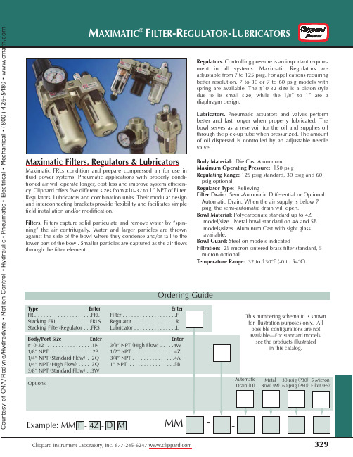
Maximatic Filters, Regulators & LubricatorsMaximatic FRLs condition and prepare compressed air for use in fluid power systems. Pneumatic applications with properly condi-tioned air will operate longer, cost less and improve system efficien-cy. Clippard offers five different sizes from #10-32 to 1” NPT of Filter,Regulators, Lubricators and combination units. Their modular design and interconnecting brackets provide flexibility and facilitates simple field installation and/or modification.Filters. Filters capture solid particulate and remove water by “spin-ning” the air centrifugally. Water and larger particles are thrown against the side of the bowl where they condense and/or fall to the lower part of the bowl. Smaller particles are captured as the air flows through the filter element.Regulators.Controlling pressure is an important require-ment in all systems. Maximatic Regulators are adjustable from 7 to 125 psig. For applications requiring better resolution, 7 to 30 or 7 to 60 psig models with spring are available. The #10-32 size is a piston-style due to its small size, while the 1/8” to 1” are a diaphragm design.Lubricators.Pneumatic actuators and valves perform better and last longer when properly lubricated. The bowl serves as a reservoir for the oil and supplies oil through the pick-up tube when pressurized. The amount of oil dispersed is controlled by an adjustable needle valve.Body Material:Die Cast Aluminum Maximum Operating Pressure:150 psigRegulating Range:125 psig standard, 30 psig and 60 psig optionalRegulator Type:RelievingFilter Drain:Semi-Automatic Differential or Optional Automatic Drain. When the air supply is below 7 psig, the semi-automatic drain will open.Bowl Material:Polycarbonate standard up to 4Z model/size. Metal bowl standard on 4A and 5B models/sizes. Aluminum Cast with sight glass available.Bowl Guard:Steel on models indicatedFiltration:25 micron sintered brass filter standard, 5 micron optionalTemperature Range: 32 to 130°F (-0 to 54°C)Ordering Guiden C o n t r o l ŀ H y d r a u l i c ŀ P n e u m a t i c ŀ E l e c t r i c a l ŀ M e c h a n i c a l ŀ (800) 426-5480 ŀ w w w .cSemi-Automatic or Automatic DrainAll FRL components are a modular design which allow easy connection and disconnection of the components for simpleinstallation and maintenance.Die Cast Aluminum BodyLarge selection of convenient mounting hardware offered#10-32 through 1” NPTports availableRegulator ensures a constant downstream airline pressureFilters prevent moisture and solid particulates from getting into compressed air linesFlow rates from 3scfm to 280 scfmPressure Gauge allows foreasy viewing25 micron filters standard, 5 micron optionalEasy-to-view sight glasses standard on all metal bowlsMetal BowlLubricators increase component life by dispensing oil into theairline supplyn C o n t r o l ŀ H y d r a u l i c ŀ P n e u m a t i c ŀ E l e c t r i c a l ŀ M e c h a n i c a l ŀ (800) 426-5480 ŀ w w w .cCombination FRLs provide airfiltration, regulation and lubrication inone unit for easy mounting andinstallation. Includes L brackets andgauge.Bowl: Polycarbonate standard. Steel bowlshields provided on models indicated.Metal bowls with sight glasses alsoavailable, add “-M” to the Part Number.Regulating Range:7 to 100 psig onMMFRL-1N, 7 to 125 psig on allothers. 30 and 60 psig ranges alsoavailable, add “-P30” or “-P60” to the endof the Part Number.Drain:Semi-Automatic standard on MM-FRLS-3 series. Manual standard on all oth-ers. Optional Automatic Drainavailable—add “-D” to thePart Number. Drains notavailable onLubricators.Filtration: 25micron filter stan-dard. Add “-F5” tothe end of the PartNumber for an optional5 micron filter.MMFRL-4ZDim. MMFRL-1 MMFRL-2 MMFRL-3 MMFRL-4W MMFRL-4A MMFRL-5BH 3.33 (84.6) 4.92 (125.0) 6.16 (156.5) 7.54 (191.5) 7.60 (193.0) 10.69 (271.5)HB 0.79 (20.1) 0.94 (23.9) 1.39 (35.3) 1.57 (40.0) 1.57 (39.9) 1.97 (50.0)HS 1.00 (25.4) 1.50 (38.1) 1.50 (38.1) 1.61 (40.9) 1.61 (40.9) 1.89 (48.0)L 3.58 (90.9) 5.51 (140.0) 7.13 (181.1) 9.37 (238.0) 9.96 (253.0) 11.81 (300.0)LS 1.3 (33.0) 1.97 (50.0) 2.52 (64.0) 3.31 (84.1) 3.50 (88.9) 4.13 (104.9)TB 0.98 (24.9) 1.18 (30.0) 1.61 (41.0) 1.97 (50.0) 1.97 (50.0) 2.75 (69.9)TG 1.02 (25.9) 2.24 (57.0) 2.39 (60.7) 2.58 (65.5) 2.74 (69.6) 2.97 (75.4)TR 0.98 (24.9) 1.57 (40.0) 2.09 (53.1) 2.76 (70.1) 2.76 (70.1) 3.54 (89.9)MMFRL-2P-DFRL with Polycarbonate Bowlsand Auto DrainMMFRL-3WFRL with Bowl ShieldsDrawing shown with PolycarbonateBowl without Shield or Auto DrainHBLLSHSHTG TBTRe/HydradyneŀMotionControlŀHydraulicŀPneumaticŀElectricalŀMechanicalŀ(8)426-548ŀwww.cStacking FRLs provide air filtration, regula-tion and lubrication in one unit for easymounting and installation.• Includes L bracket and gaugeBowl:Polycarbonate standard. Steel shield provided onmodels indicated. Metal bowls with sight gauges alsoavailable, add “-M” to the end of the Part Number.Regulating Range:7 to 100 psig on MMFRLS-1N, 7 to 125psig on all others. 30 and 60 psig ranges also available, add“-P30” or “-P60” to the end of the Part Number.Drain:Semi-Automatic standard on MMFRLS-3/4/5 series.Manual standard on all others. Optional Automatic Drainavailable—add “-D” to Part Number.Filtration:25 micron filter standard. Add “-F5” to the end ofthe Part Number for an optional 5 micron filter.Part No.Port Gauge Port Flow Rate Bowl Shield GaugeMMFRLS-4ZDim. MMFRLS-1 MMFRLS-2 MMFRLS-3 MMFRLS-4W MMFRLS-4A MMFRLS-5BH 4.31 (109.5) 6.48 (164.6)8.31 (211.1)10.31 (261.9)10.51 (267.0)13.31 (338.1)HB0.79 (20.1)0.94 (23.9) 1.38 (35.1) 1.57 (39.9) 1.57 (39.9) 1.97 (50.0)HS 1.99 (50.5) 3.07 (78.0) 3.64 (92.5) 4.41 (112.0) 4.49 (114.0) 4.57 (116.1)L 2.28 (57.9) 3.54 (89.9) 4.61 (117.1) 6.06 (153.9) 6.46 (164.1)7.68 (195.1)LS 1.14 (29.0) 1.77 (45.0) 2.30 (58.4) 3.03 (77.0) 3.23 (82.0) 3.84 (97.5)TB0.98 (24.9) 1.18 (30.0) 1.61 (40.9) 1.97 (50.0) 1.97 (50.0) 2.75 (69.9)TG 1.02 (25.9) 2.24 (56.9) 2.39 (60.7) 2.58 (65.5) 2.74 (69.6) 2.97 (75.4)TR0.98 (24.9) 1.57 (39.9) 2.09 (53.1) 2.76 (70.1) 2.76 (70.1) 3.54 (89.9)Drawing shownwithout Shieldor Auto Draindyne/HydradyneŀMotionControlŀHydraulicŀPneumaticŀElectricalŀMechanicalŀ(8)426-548ŀwww.c。
Subject title CMA200Advanced Independent-Metering Mobile Valve200LPM440 barCAN BusContents2EATON CMA200 Technical Document E-VLMB-BB002-E1 September 2016The CMA200 is an advanced CAN-Enabledelectro-hydraulic sectional mobile valve with independent metering that utilizes pressureand position sensors, on board electronics, and advanced software control algorithms. Where conventional mobile valves often compromiseon precision or response, the CMA delivers both. The CMA offers high performance with sub micron hysteresis, closed loop control over the spool position, and repeatable performance.CMA offers customers the next generation in advanced mobile valves with unlimited possibilities to differentiate your machine capabilities.Key Benefits of this advanced mobile valve include:• Precise control maintained for all load conditions• Reduction in metering losses / energy management• High valve responsiveness• Flow Sharing – Pre and Post Comp Capabilities• Flexibility in configuration / easily change parameters• Command factory-calibrated flow or pressure from eitherwork port• Easier communication with the valve• Reduced load on the Vehicle CAN bus• Advanced Diagnostics for improved reliability and productivity • Hose Burst Detection• Limp mode• Diagnostics on the inlet, tank, load sense, work port pressures, spool position, consumed flow, and oil temperature.• Platform can support future software development for future product development.• Reliable performance across a broad temperature rangeIntroductionEATON CMA200 Technical Document E-VLMB-BB002-E1 September 2016 3CMA200 Specificationsand PerformanceInlet Rated and Work Port 380 bar (5511 psi)Inlet Max and Work Port 440 bar (6382 psi)Tank* Max 30 bar (435 psi)FlowWork Port (max with highflow spools, measured withinternal pressure sensors) 200 lpm (53 gpm) @ 16 bar Δ P Max inlet flowwhen two sections are fully open.400 lpm (106 gpm) @ 35 bar P-T Leakage**Max Leakage withoutWork Port Valves 30 cc @100 bar @ 21 cstMax Leakage withWork Port Valves 40 cc @100 bar @ 21 cst ConstructionSectional Up to 8 sections per blockUp to 15 sections per VSMPort TypesSAE P1 & P2 = 1 1/16”-12 UN (SAE-12),T = 1 5/16”- 12 UN (SAE-16), LS =7/16”-20 UNF (SAE-04), A&B = 3/4”-16 UNF (SAE-08) OR 7/8”-14 UNF(SAE-10) OR 1 1/16”-12 UN (SAE-12) BSP P1 & P2=G 3/4, T=G 1, LS=G 1/4,A&B = G 1/2 OR G 3/4Inlet section optionsVariable Displacement(Load Sensing)Fixed DisplacementWork section optionsLow Flow Spools 100 lpm (26 gpm)High Flow Spools 200 lpm (53 gpm)Work Port Valves Anti-CavitationPort Relief & Anti-CaviationPort ReliefCompensation typeDigital On meter-in and meter-out ActuationPrimary CANEmergency Mechanical OverrideControl modesFlowPressureSpool PositionFloat Ambient (operating) -40°C to 105°CStandard Oil (operating)***** -40°C to 85°CExtended Oil (operating) -20°C to 105°CStorage -40°C to 105°CFiltrationISO 4406 18/16/13Pressure Reducing Valve 75 micronPilot Valve 100 micronElectromagnetic protectionEMC Directive 2014/30/EC ***Earth Moving ISO 13766: 2006 Construction EN 13309: 2010Agriculture ISO 14982:2009Electrical environmental****Ingress Protection IP67Thermal Cycling -40C to 105C for 1000 cycles Mechanical Shock 50G ½ sine wave, 11ms pulse Random VibrationMethod MIL STD 202G, Method 214-1 Limits Test Condition A Duration 8 hrs/axis # Of Axis 3 separatelyProfile Reference AppendixOil Temperature viscosityRecommended Viscosity 85 to 10 cStAbsolute Maximum Viscosity 2250 cStAbsolute Minimum Viscosity 7 cStElectricalInput Voltage 9 - 32 VDCPower Consumption Range Reference AppendixCAN Interface J1939 2.0B, CAN OpenElectrical interface connectorsDeutsch (VSM) DT06-12SB-P012Deutsch (VSE) DT06-12SA-P012Dynamic performanceLoop Time for Internal CAN 3msTypical Step Response 24 ms @ 15 cStTypical Frequency Response 17.5 Hz @ 15 cStPressures Temperatures* W ith manual override, tank limited to 10 bar (145 psi) maximum. Max 30bar is at constant rate.**Data taken from work port to tank and supply***Electronics are designed to power down and recover automatically undervarious power conditions (ie.. Load Dump, Ignition Cranking, Disconnectionof Inductive Loads). CE testing with J1939 at 250 kb/s****Additional Electrical Environmental tests were performed. ContactEaton for additional details, if desired.*****It is recommended that the CMA valves not be subjected to a thermaldifference of greater than 50°F (28°C).EATON CMA200 Technical Document E-VLMB-BB002-E1 September 20164Valve cross section:1. Pilot Valve2. Main Stage3. Linear Position Sensor4. Port Reliefs / Anti-Cavs5. Main Metering Spools6. Work Port A7. Work Port B 123475 6CMA200 Advanced Sectional Mobile ValvesCross SectionsEATON CMA200 Technical Document E-VLMB-BB002-E1 September 2016 5Principles of OperationThe work section is comprised of two independent spoolsthat act as a pair working to control double acting services, or alternatively as single spools controlling a single acting service (2 single axis services can be controlled from any work section).Demands to each work section are transmitted over a CAN Bus and power is provided to eachwork section via a single daisychain cable arrangement. Eachwork section has a single pilotvalve comprised of on-boardelectronics, embedded sensors,and two independent 3 position4 way pilot spools driven by alow power embedded microcontroller.The independent pilot spoolscontrol the mainstage spools.Closed loop control of eachwork section is done locallyby leveraging the on-boardelectronics and sensors.Each mainstage spool has itsown position sensor enablingclosed loop position control ofthe mainstage spool.Further, a pressure sensoris located in each work port,pressure line and tank line.With the up and downstreampressure information known atany time, flow delivered to theservice can be controlled bymoving the spools to create theappropriate orifice area for thedesired flow rate. Figure 1: CMA system with Load-Sensing Inlet & a single work-sectionFigure 2: CMA system with Fixed Displacement Inlet & a single work-sectionCMA200 Advanced Sectional Mobile ValvesEATON CMA200 Technical Document E-VLMB-BB002-E1 September 20166CMA200 Advanced Sectional Mobile ValvesFigure 3: Extension InletEATON CMA200 Technical Document E-VLMB-BB002-E1 September 2016 78There are multiple interconnection options for the CMA200 valve systems.The following illustrates possible system configuration options. Configuration is dependent on application requirement and is constrained by the following rules:• Sectional construction with up to 8 sections per bank • Maximum 15 sections per Valve System Module (VSM)• One VSM and CV required per system• If distance between an extension valve bank and the VSM or VSE is less than 6 meters, they can be connected using a daisy chain extension cable. See options on page 12• If distance between valve banks is greater than 6 meters, they must be connected using a VSE and external wiring harness. Max distance between a VSM and VSE is 30 meters. See page Total Interconnect CAN(ICAN) Wiring LengthsN e t w o r kUser CAN, or UCAN, is the machine’s CAN network that communicates with the VSM.If the VSM is at the end of the UCAN network, a 120 ohm termination resistor built into the VSM can be User Ca bles T ermina tion• No more than two (2) valve system extenders (VSE) per system • If more than 15 work sections are required, this can by accomplished by using additional CMA systems and theircorresponding VSM. Additional VSMs will appear as another Node on the User CAN Network.• If application specific Electromagnetic Compatibility testing indicates CAN cable shielding is needed, connect CAN shield as shownCMA Wiring Harness DetailsEATON CMA200 Technical Document E-VLMB-BB002-E1 September 2016 9Single block system5 UCAN HIGH A 2 SHIELD 4 UCAN LOW B10 ICAN HIGH B 12 BATTERY -1 BATTERY + 9-32 VDC7ICAN TERMINATE9ICAN LOW A8 ICAN HIGH A 11 ICAN LOW B 6 UCAN TERMINATE 3 UCAN LOW A 120OHMVSMUser CAN Connection1 BATTERY + 9-32 VDC 7 ICAN TERMINATE9ICAN LOW A8 ICAN HIGH A 11 ICAN LOW B 6SECOND VSE ID2 SECOND VSE ID RETURN NC NC NC 10 ICAN HIGH B12 BATTERY -Us5 UCAN HIGH A 3 UCAN LOW A 2 SHIELD 4 UCAN LOW B 10 ICAN HIGH B12 BATTERY -1BATTERY + 9-32 VDC7 ICAN TERMINATE 9 ICAN LOW A 8ICAN HIGH A11 ICAN LOW B 6 UCAN TERMINATE Valve Block 1Valve Block 2120OHMVSEVSM120OHMUser CAN ConnectionCASE SCREWDouble block system with valve system extender (VSE)5 UCAN HIGH A 2 SHIELD 4 UCAN LOW B10 ICAN HIGH B 12 BATTERY -1 BATTERY + 9-32 VDC 7ICAN TERMINATE9 ICAN LOW A 8 ICAN HIGH A 11 ICAN LOW B 6 UCAN TERMINATE 3UCAN LOW A120OHMVSMUser CAN Connection1 BATTERY + 9-32 VDC7 ICAN TERMINATE 9ICAN LOW A8 ICAN HIGH A 11 ICAN LOW B6 SECOND VSE ID2 SECOND VSE ID RETURN NCNC NC 10 ICAN HIGH B 12 BATTERY -5 UCAN HIGH A 3 UCAN LOW A 2 SHIELD 4 UCAN LOW B 10 ICAN HIGH B12 BATTERY -1BATTERY + 9-32 VDC 7ICAN TERMINATE 9 ICAN LOW A 8 ICAN HIGH A 11 ICAN LOW B6 UCAN TERMINATE Valve Block 1Valve Block 2120OHMVSEVSM120OHMUser CAN ConnectionCASE SCREWInterconnect CAN, or ICAN, is the CAN network between the VSM and VSE’s.120 ohm termination resistors in the VSM and VSE’s circuits can be connected with the installation ofwire jumpers each device. Two sets of ICAN pins are available in a VSM or VSE to allow daisy chaining ICAN if a VSM/VSE is in the middle of the CMA system. If no VSE’s exist in a system, it is still necessary to install a jumper to activate one 120 ohm termination resistor on the ICAN bus.Interconnect CAN T ermina tionCMA Wiring Harness DetailsEATON CMA200 Technical Document E-VLMB-BB002-E1 September 201610CMA Wiring Harness DetailsCMA Wiring Harness DetailsTEATON CMA200 Technical Document E-VLMB-BB002-E1 September 2016 11EATON CMA200 Technical Document E-VLMB-BB002-E1 September 201612Work Section Options – Software VersionsSo tware DescriptionPressure compensated flow control Load-independent flow controlFlow compensated pressure control Single service pressure control while either sinking or sourcing flow.Intelli floatLowers the load at a configurable rate and then enters full float modeStandard ratio flow share Pre or post comp capabilities in one valve block. All service flow demands are reduced by the (with priority capability) same ratio. Can also exempt services from flow-sharing to maintain priority. This feature prevents the pump from saturating when flow demands to the valve sum to be larger than thepump can provide.Intelligent twin spool flow control (IFC)V ersatile flow controller which maintains the desired flow independent of transitions between passive and overrunning loadsLoad damping A feature of IFC and UFC which reduces service oscillation induced by moving large structures, such as a boom.Electronic load sense enabled E nables operation with a compatible pump or when multiple CMA systems are presenton the same CAN networkElectronic work port relief valve Configurable electronically controlled relief valve against externally applied loads Electronic work port pressure limit (feed reducer) C onfigurable electronically controlled pressure limit applied to user flow demandswithout consuming additional pump flow Single spool flow controlSink or source flow on individual service ports Single spool position control Direct spool position control on each spool Smart Data D iagnostics on all on-board sensors. Inlet, Tank, LS, Work Port pressures, Spool Positions, oiltemperature sensor data availability.A - Standard software control featuresSo tware DescriptionTorque ControlAdvanced force or torque control for double-acting cylinders or motors Data control packageBroadcast of each spool’s flow consumptionCascade and Uniform Flow Share Cascade: maintains demanded flow to selected high priority services by reducing flow to lowest priority servicesU niform: All flow demands are reduced by the same absolute amount (i.e. all reduced by 1 lpm)So tware DescriptionHose burst detection P revents major oil spill events by monitoring flow consumption on each service and closing the spools for that circuit if a major leak is detected Limp modeI f a sensor fails, the valve will continue to work with reduced performance until the machine can be servicedU – Advanced control packageV – Advanced service packageT – All PackagesIncludes Standard, Advanced Control, and Advanced Service packagesEATON CMA200 Technical Document E-VLMB-BB002-E1 September 2016 13CMA200 Advanced Sectional Mobile ValveCMA200 Installation Views: 8 Section Inlet Block With Manual OverrideUnits: mmDimension /1/2/3/4/5/6/7/8A (mm)56.0112.0168.0224.0280.0336.0392.0448.0Weights (kg)26.534.642.850.959.167.375.483.6Number of sections A ’ sideSeries connectorEATON CMA200 Technical Document E-VLMB-BB002-E1 September 201614Dimension /1/2/3/4/5/6/7/8A (mm)56.0112.0168.0224.0280.0336.0392.0448.0Weights (kg)24.732.339.847.354.862.369.877.4Number of sections CMA200 Advanced Sectional Mobile ValveCMA200 Installation Views: 8 Section Inlet Block Without Manual OverrideUnits: mmboth endsEATON CMA200 Technical Document E-VLMB-BB002-E1 September 2016 15CMA200 Advanced Sectional Mobile ValveCMA200 Installation Views: 8 Section Extension Block With Manual OverrideUnits: mmBracket location Corientation. Brackets also available 3 tie rodsA ’ sideSeries connectorboth endsDimension /1/2/3/4/5/6/7/8A (mm)56.0112.0168.0224.0280.0336.0392.0448.0Weights (kg)24.332.440.648.756.965.173.281.4Number of sectionsEATON CMA200 Technical Document E-VLMB-BB002-E1 September 201616CMA200 Advanced Sectional Mobile ValveCMA200 Installation Views: 8 Section Extension Block Without Manual OverrideM10 X 1Units: mmDimension /1/2/3/4/5/6/7/8A (mm)56.0112.0168.0224.0280.0336.0392.0448.0Weights (kg)22.530.137.645.152.660.167.675.1Number of sectionsModel Code For Inlet Section1CMA200 Series2Communication Protocol J J1939C CAN OPEN0 None3Interface ModuleM VSME VSE0 None4Port T ypesS SAE P1 = 1 1/16”-12UN (SAE-12)P2 = 1 1/16”-12UN (SAE-12)T = 1 5/16”- 12UN (SAE-16)LS = 7/16”-20UNF (SAE-04)B BSP P1= G 3/4P2= G 3/4T = G 1LS= G 1/45Inlet Pressure ControllerV VariableDisplacementF Fixed Displacement0 none, Used on VSEor extension block6Active Pressure Port1 P13 P1 & P27Manual Override0 NoneM Manual Overrideon CV8Main Relief Setting(In bar)000 = None155 293172 310190 328207 345224 362241 379259 397276 4149Pa int T ypeK Std. Flat Black10 Se a ls1 Default11Special Features00 None12Software VersionXXA Standard Software13Design Code10 Design Code214CMA200 * * * * * * *** * * ** *** **59811131236710Note: A pressure limit can be set on the valve in software to any value in increments of 0.01 barusing available configuration software suite. This applies to both inlet and work port settings.Note: No relief valve is available for extension inlets.EATON CMA200 Technical Document E-VLMB-BB002-E1 September 2016 17EATON CMA200 Technical Document E-VLMB-BB002-E1 September 201618214CMZ200 * ** * *** ** * *** * * ** *** ** **5981113141236710Model Code – Work Section1 CMZ200 Series2 Body Port Thread Sizes A 3/4” 16 UNF (SAE-8)B 7/8” 14 UNF (SAE-10)C 1-1/16” 12 UN (SAE-12)D G 1/2”E G 3/4”3 Spool T ype at Position AHC 200 lpm, biasedto centerHT 200 lpm, biased to tankHP 200 lpm, biased to pressure LC 100 lpm, biased to centerLT 100 lpm, biased to tankLP 100 lpm, biased to pressure4 Valve Option at A0 NoneB Anti-cavitation valve with relief valveC Anti-cavitation valve S Relief valve 5 Relief Setting at Position ARV Setting in Bar 000 = None155 293 172 310 190 328 207 345 224 362 241 379 259 397 276 4146 Spool T ype at Position BHC 200 lpm, biased to centerHT 200 lpm, biased to tankHP 200 lpm, biased to pressure LC 100 lpm, biased to centerLT 100 lpm, biased to tankLP 100 lpm, biased to pressure7 Valve Option at B0 NoneB Anti-cavitation valve with relief valveC Anti-cavitation valve S Relief valve 8 Relief Setting at Position BRV Setting in Bar 000 = None 155 293 172 310 190 328207 345 224 362241 379 259 397276 4149 Manual Override T ype0 NoneA Lever-handle toward port AB Lever-handle toward port B 10 Pa int T ypeKStd. Flat Black11 Seal1 Default (NBR)12 Special Features00 None13 Software VersionXXA Standard SoftwareXXU Advanced Control PackageXXV Advanced ServicePackage XXT All Packages(Standard plus all Advanced Packages)14 Design Code10 Design CodeNote : A pressure limit can be set on the valve in software to any value in increments of 0.01 barusing available configuration software suite. This applies to both inlet and work port settings.Note : If an option without a relief is selected for port A or B, no relief valve setting should be selected in corresponding Relief Setting position (i.e., select 000). Likewise, when selecting a valve option with a relief, make sure to select a corresponding relief setting.Note : High flow or low flow spools must be selected for both work ports. They cannot be mixed (i.e. a high flow spool on work port A and low flow spool on work port B).NotesEATON CMA200 Technical Document E-VLMB-BB002-E1 September 2016 19© 2016 EatonAll Rights Reserved Printed in USADocument No. E-VLMB-BB002-E1 September 2016EatonHydraulics Group USA 14615 Lone Oak Road Eden Prairie, MN 55344USATel: 952-937-9800Fax: 952-294-7722/hydraulicsEatonHydraulics Group Europe Route de la Longeraie 71110 Morges SwitzerlandTel: +41 (0) 21 811 4600Fax: +41 (0) 21 811 4601EatonHydraulics Group Asia Pacific Eaton BuildingNo.7 Lane 280 Linhong Road Changning District,Shanghai 200335ChinaTel: (+86 21) 5200 0099Fax: (+86 21) 2230 7240。
中华实验眼科杂志2021年3月第39卷第3期Chin J Exp Ophthalmol,March2021,Vol.39,No.3•253•华眼科杂志,2018,54(9):649-651.DOI:10.3760/cma.j.issn.04124081.2018.09.003.Li B,Bai HX.Cautious choice of vitrectomy in patients with retinoblastoma[J].Chin J Ophthalmol,2018,54(9):649-651.DOI;10.3760/cma.j.issn.0412-4081.2018.09.003.[29]陈大年,高静歌•重视对种植瘤的研究,迎接视网膜母细胞瘤治疗的新变革[J]•中华实验眼科杂志,2015,33(11):961-964.DOI:10.3760/cma.j.issn.2095-0160.2015.11.001.Chen DN,Gao JG.Are you ready?The new era of targeted local chemotherapy for retinoblastoma is comingf J].Chin J Exp Ophthalmol, 2015,33(11):961-964.DOI:10.3760/cma.j.issn.2095-0160.2015.11.001.[30]Shields CL,Bianciotto CG,Jabbour P,et al.Intra-arterial chemotherapyfor retinoblastoma:report No.1,control of retinal tumors,subretinal seeds,and vitreous seeds[J].Arch Ophthalmol,2011,129(11): 1399-1406.DOI:10.1001/archophthalmol.2011.150.[31]Munier FL,Gaillard MC,Balmer A,et al.Intravitreal chemotherapy forvitreous disease in retinoblastoma revisited:from prohibition to conditional indications[J].Br J Ophthalmol,2012,96(8): 1078-1083.DOI:10.1136/bjophthalmol-2011-301450.[32]Yousef YA,Halliday W,Chan HS,et al.No ocular motilitycomplications after subtenon topotecan with fibrin sealant for retinoblastoma[J].Can J Ophthalmol,2013,48(6):524-528.DOI:10.1016/j.jcjo.2013.05.01&[33]Mendoza PR,Grossniklaus HE.Therapeutic options for retinoblastoma[J].Cancer Control,2016,23(2):99-109.DOI:10.1177/10732748 1602300203.[34]高静歌,陈大年.视网膜母细胞瘤眼动脉内化疗有效性及安全性的系统评价[J]•中华实验眼科杂志,2016,34(11):1031-1037.DOI:10.3760/cma.j.issn.2095-0160.2016.11.015.Gao JG.Chen DN.A systematic review of the efficiency and safety of intra-arterial chemotherapy for retinoblastoma[J].Chin J Exp Ophthalmol,2016,34(11):1031-1037.DOI:10.3760/cma.j.issn.2095-0160.2016.11.015.[35]Ji XD,Lu SL,Zhao PQ.Vitrectomy for localized vitreous seeds ofretinoblastoma in an only eye[J].Chin Med J,2013,126(13):2589-2590.DOI:10.3760/cma.j.issn.0366-6999.20130425. [36] Smith SJ,Smith BD.Evaluating the risk of extraocular tumour spreadfollowing intravitreal injection therapy for retinoblastoma:a systematic review]J].Br J Ophthalmol,2013,97(10):1231-1236.DOI;10.1136/bjophthalmol-2013-303188.[37]Francis JH,Abramson DH,Ji X,et al.Risk of extraocular extension ineyes with retinoblastoma receiving intravitreous chemotherapy[J].JAMA Ophthalmol,2017,135(12):1426-1429.DOI:10.1001/ jamaophthalmol.2017.4600.[38]张亚男,白海霞,毛英,等•视网膜母细胞瘤玻璃体切除术后复发眼的组织病理学分析[J].中华眼科杂志,2019,55(11):854-859.D01:10.3760/cma.j.issn.0412-4081.2019.11.012.Zhang YN,Bai HX,Mao Y,et al.Analysis of the histopathological features of recurrent retinoblastoma after vitrectomy[J].Chin J 0phthalmol,2019,55(ll):854-859.DOI:10.3760/cma.j.issn.0412-4081.2019.11.012.[39]张举,顼晓琳,李彬,等.葡萄膜黑色素瘤瘤体生长对视网膜和巩膜浸润的影响[J].中华眼科杂志,2016,52(10)=749-754.DOI:10.3760/cma.j.issn.0412-4081.2016.10.007.Zhang J,Xu XL,Li B,et al.Characteristics of retinal and scleral infiltration in uveal melanoma[J].Chin J Ophthalmol,2016,52(10): 749-754.DOI:10.3760/cma.j.issn.0412-4081.2016.10.007. [40]吕红彬,罗清礼,唐健,等.脉络膜黑色素瘤组织病理学分析[J].中华眼底病杂志,2006,22(3)=161-165.Lyu HB,Luo QL,Tang J,et al.Histopathological analysis of choroidal melanoma[J].Chin J Ocul Fundus Dis,2006,22(3):161—165. [41]Suesskind D,Ulmer A,Schiebel U,et al.Circulating melanoma cells inperipheral blood of patients with uveal melanoma before and after different therapies and association with prognostic parameters:a pilot study[J],Acta Ophthalmol,2011,89(1):17-24.DOI:10.Ull/j.1755-3768.2009.01617.x.[42]Caminal JM,Mejia K,Masuet-Aumatell C,et al.Endoresection versusiodine-125plaque brachytherapy for the treatment of choroidal melanoma[J].Am J Ophthalmol,2013,156(2):334-342.DOI:10.1016/j.ajo.2013.03.036.[43]Garcia-Arumi J,Leila M,Zapata MA,et al.Endoresection techniquewith/without brachytherapy for management of high posterior choroidal melanoma:extended follow-up results[J].Retina,2015,35(4): 628-637.DOI:10.1097/IAE.0000000000000379.[44]张小燕,温莹.微创玻璃休切割术联合局部完整剥除治疗脉络膜黑色素瘤[J].中华眼视光学与视觉科学杂志,2019,21(8):581-585.DOI:10.3760/cma.j.issn.1674-845X.2019.0&004.Zhang XY,Wen Y.Minimally invasive vitrectomy combined with local intact exfoliation for the treatment of choroidal melanoma[J].Chin J Optom Ophthalmol Vis Sci,2019,21(8):581-585.DOI:10.3760/ cma.j.issn.1674-845X.2019.08.004.(收稿日期:2020-07-11修回日期:2021-01-30)(本文编辑:尹卫靖张宇)读者・作者・编者本刊对基金项目的证明和著录要求文稿所涉及的课题如为国家级、部级、省级等基金资助项目,请分别用中英文表述并分别列于文章中英文摘要关键词之下,“基金项目:”进行标识,并注明基金项目名称,并在圆括号内注明基金项目编号。
儿童胡桃夹综合征50例临床分析施冬雪;罗钢【摘要】目的探讨儿童胡桃夹综合征(NCS)的临床特点.方法回顾性分析2005年1月至2015年10月我院儿科收治的50例NCS患儿的临床特点.结果 50例患儿中,27例(52.9%)为单纯性蛋白尿,13例(25.5%)为单纯性血尿,10例(19.6%)表现为血尿伴蛋白尿;23例有血尿患儿中,8例(34.8%)为非肾小球性血尿,15例(65.2%)为肾小球性血尿;37例有蛋白尿患儿中,29例(78%)为直立性蛋白尿,且均无明显的大量蛋白尿;左肾静脉扩张部内径(a)与狭窄部内径(b)比值与24 h尿蛋白定量及尿微量蛋白均无显著相关性(P>0.05).结论儿童NCS肾脏改变以蛋白尿为主,主要为少量蛋白尿和直立性蛋白尿;24 h尿蛋白定量及尿微量蛋白值与a/b比值变化无关;血尿现象,特别是肾小球性血尿,在NCS中并不少见.【期刊名称】《中国医科大学学报》【年(卷),期】2016(045)010【总页数】4页(P939-941,957)【关键词】胡桃夹综合征;蛋白尿;血尿;微量蛋白尿【作者】施冬雪;罗钢【作者单位】中国医科大学附属第一医院儿科,沈阳110001;中国医科大学附属第一医院儿科,沈阳110001【正文语种】中文【中图分类】R725胡桃夹综合征(nutcracker syndrome,NCS)是指左肾静脉在穿过腹主动脉与肠系膜上动脉汇入下腔静脉的行程中受到挤压,从而引起血尿、蛋白尿、左腰腹疼痛等临床症状的疾病,也被称为左肾静脉受压综合征[1]。
如果仅发现左肾静脉受压迫,而无其他相关的临床症状,则称为胡桃夹现象(nutcracker phenomenon,NCP)[2],上世纪70年代和90年代DE SCHEPPER和SHINTAKU首次对NCP引起的血尿和直立性蛋白尿进行了报道[3]。
由于以往人们对NCS的认识不足,常被误诊为肾小球肾炎等而予以免疫抑制剂治疗[4]。
AIR DATA ACCESSORIES KITMODEL No. DH8-834M DASH8-100/200/300/400AIRCRAFTTo buy, sell, rent or trade-in this product please click on the link below:https:///Nav-Aids-Ltd-DH8-834M-Air-Data-Accessory-Kit-for-Dash-8-100-200-300-400-Aircraft.aspxAIR DATA ACCESSORIES KITMODEL No. DH8-834MDASH8-100/200/300/400 AIRCRAFTApril 14, 2009Page 2 of 3This kit contains all the equipment required to test from source the complete pitot & static air data system on the Dash 8-100/200/300/400 aircraft, as well as the means of pre-testing all adaptors and hoses prior to being fitted to the aircraft.Pitot Test AdaptorPart No. P22201-3 (2 req’d.) (Dash 8-100/200/300)These units fit the pitot probes P/N PH1100-1DH located on each side of the aircraft and when installed they will isolate and test each system separately orsimultaneously, using pitot hose assembly supplied. Pre-Test ProbePart No. PT11882 (2 req’d.) (Dash 8-100/200/300)When it becomes necessary to test the integrity of the pitot test adaptors and/or hoses and test set, these units are installed into the pitot test adaptors thus simulating the pitot head.Static Test Adaptor Part No. S51089-4 (1 req’d.) (Dash 8-100/200/300)This unit fits the Captain’s, F.O. and alternate static ports on the aircraft. This is a composite static vent.N.B. Attach the hose to unit before installing on aircraft.Static Blanking Adaptor Part No. S51089B (1 req’d.) (Dash 8-100/200/300)This unit is used in conjunction with theabove mentioned test adaptor and is used to blank off the matching static vent on the opposite side of the aircraft. A test port is provided on the unit should it be desirable to check the integrity of the unit. Static Pre-Test Plate Part No. PT14097 (2 req’d.) (Dash 8-100/200/300)These units are mounted onto the case cover and also act as storage pad. Before testing the integrity of the static test adaptors ensure that the mounting bolts are tight. The static testing and blanking adaptors may be tested separately or as a pair by connecting with the static hose assembly DH-7270CB. Pitot & Dual Static Test Adaptor Part No. PSS22202M-3-4-4 (2 req’d.) (Dash 8-400)These units fit the pitot probes P/NC14135DA & C14135CA located on the nose and when installed they will isolate and test each system separately or simultaneously. Pre-Test ProbePart No. PT421-202M (2 req’d.) (Dash 8-400)When it becomes necessary to test theintegrity of the pitot & dual static test adaptors and/or hoses and test set, these units are installed into the adaptors thus simulating the pitot head.AIR DATA ACCESSORIES KITMODEL No. DH8-834MDASH8-100/200/300/400 AIRCRAFTApril 14, 2009Page 3 of 3Pitot Static Adaptor - Standby Part No. PS22203M-3-4 (1 req’d.) (Dash 8-400)This unit fits the pitot static probe, P/N C16193BA, located on the nose of the aircraft. Pre-Test ProbePart No. PT421-203M (1 req’d.) (Dash 8-400)When it becomes necessary to test theintegrity of the pitot static test adaptor and/or hoses and test set, this unit is installed into the adaptor thus simulating the pitot head. Pitot Test Hose Assembly Part No. DH-7270CB (1 req’d.) (Dash 8-100/200/300/400)This hose is connected to each pitot inlet of the adaptors and is fitted with double acting quick disconnects for use when it is desirable to test only one pitot system. The connection for the pitot outlet of the pneumatic generator is included on this assembly. Static Test Hose Assembly Part No. DH-5160CB (1 req’d.) (Dash 8-100/200/300/400)This assembly attaches to the static fittings. The double acting quick disconnects operate in the same manner as that on the pitot test hose assembly. The extension fitting then connects to the static outlet hose of the pneumatic generator.Lubricating Fluid Part No. LF5050 (1 req’d.)This fluid is used to lubricate the glands of the pitot & dual static and pitot static test adaptors. It is recommended that a small amount be used before installing adaptors on pitot head to ensure smooth installation onto the pitot probe.Seal Kit - Part No. SK201Two sets of spare seals for pitot test adaptors P/N P22201-3 are stowed in the case. Seal Kit - Part No. SK202MTwo sets of spare seals for pitot & dual static test adaptors - P/N PSS22202M-3-4-4 are stowed in the case. Seal Kit - Part No. SK203MOne set of spare seals for standby pitot static test adaptor - P/N PS22203M-3-4 is stowed in the case.Manual - Part No. 444-DH8-834 One manual is supplied with each kit. The equipment is enclosed in a case assembly - Model No. 110XD-DH8-834.。

乙级非密封放射性物质工作场所辐射安全规范化管理技术要求一、总纲(一)严格执行《中华人民共和国放射性污染防治法》、《放射性同位素与射线装置安全和防护条例》、《放射性物品运输安全管理条例》、《放射性废物安全管理条例》等辐射安全防护和环境保护方面的法律、法规、标准。
接受环境保护行政主管部门及其他相关部门的监管。
(二)依法办理环境影响审批、验收、辐射安全许可证等环境保护相关手续。
严格按照辐射安全许可证规定许可种类、范围和许可证条件从事辐射工作。
持有环保部门颁发的在有效期内的辐射安全许可证,许可种类和范围为“使用乙级非密封放射性物质工作场所”。
(三)按照相关法规要求,建立辐射安全和防护工作管理体系及相应管理制度,落实安全责任,单位法人对本单位辐射工作的安全和防护负总责,并依法对造成的放射性危害承担责任。
(四)建立、健全本单位辐射安全管理体系、岗位职责、操作规程、辐射防护措施(含防护用品和监测仪器)、台帐管理制度、培训计划、监测方案、个人剂量监测和健康管理制度、辐射应急预案,并做好落实工作。
(五)定期开展辐射应急培训,组织应急演练,有效应对辐射事故(件)。
(六)依法对本单位放射性同位素使用工作的安全和防护状况进行年度评估,编写年度评估报告,于每年1月31日前报原发证机关。
年度报告包含环境保护部18号令《放射性同位素与射线装置安全和防护管理办法》规定的相应内容。
(七)根据有关规定、主管部门的要求和经验反馈及时修订本单位的规章制度及应急预案。
二、辐射安全管理体系和岗位职责为加强和规范放射性同位素使用的使用,消除辐射安全隐患,预防辐射事故(件)的发生,保障辐射工作人员和公众的健康与安全,保护环境,成立辐射安全防护管理机构。
具体要求:1) 管理机构的人员不少于5人。
其中,安全管理机构的负责人由单位法人兼任,主管辐射安全管理工作的领导任管理机构的副职,辐射工作及相关部门(安全、保卫、质保等)经理及主要辐射工作人员为成员。

钢结构工程质量检查控制要点一、检查依据1.国家标准《钢结构工程施工质量验收规X》GB50205-20012.国家标准《钢结构设计规X》GB50017-20033.国家标准《冷弯薄壁型钢结构技术规X》GB50018-20024.国家标准《钢结构工程质量检验评定标准》GB50221—955.国家标准《碳素结构钢》GB/T700—886.国家标准《低合金高强度结构钢》GB/T1591—947.行业标准《建筑钢结构焊接规程》JGJ81—20028.行业标准《高层建筑钢结构技术规程》JGJ99—989.行业标准《钢结构高强度螺栓技术规程》JGJ82—9110.行业标准《网架结构工程质量检验评定标准》JGJ78—9111.标准化协会标准《门式钢架轻型房屋钢结构技术规程》 CECS 102:200212.标准化协会标准《钢结构防火涂料应用技术规X》 CECS 24:9013.某某地方标准《钢结构防火涂料工程施工验收规X》DB29-134-200514.施工图设计文件二、施工前质量控制重点内容1、现场施工单位资质、质量保证体系审查与钢结构加工厂资质审查(1)钢结构工程施工单位应具备相应的钢结构工程施工资质,从事钢结构工程施工的施工企业资质等级标准分为一、二、三级。
施工现场质量管理应有相应的施工技术标准、质量管理体系、质量控制与检验制度,施工现场应有经技术负责人审批的施工组织设计、施工方案等技术文件。
(2) 监理单位对钢结构分包单位的认可记录。
必须明确监理合同中是否对钢结构加工过程进展监理,建议建设单位在监理合同书中明确规定。
2、监理单位资质、质量控制体系审查(1) 监理企业承当监理任务应与其资质相符。
监理人员配备必须符合招投标文件规定,假如调换人员必须由建设单位的书面同意文件。
项目总监兼管其他工地的,数量不得超过3个工程,而且必须提供各个工程建设单位的书面认可文件。
在满足上述条件下,每个工程必须配备一名总监代表,总监代表应持证上岗。
汽车安全辅助驾驶支持系统信息感知技术综述3王贵槐 万 剑(武汉交通职业学院 武汉430062) (武汉理工大学 武汉430063)摘 要 随着我国汽车保有量的激增,汽车驾驶安全日渐重要。
围绕人2车2路系统中的人和路开发车载汽车安全驾驶支持系统受到广泛的关注。
在智能运输系统的交通安全研究中,与汽车安全辅助驾驶系统相关的信息感知技术研究主要有:车辆状况检测、交通环境的检测、非常规条件下驾驶员视觉增强和对驾驶员的检测等。
文中将对上述汽车安全辅助驾驶支持技术国内、外最新研究现状进行综述,并展望该领域研究动向。
关键词 智能运输系统;交通安全;安全辅助驾驶系统中图分类号:U491 文献标志码:A 引 言目前,随着我国汽车保有量的激增,汽车驾驶安全问题日渐重要。
道路交通安全研究已经成为热点,特别是围绕人2车2路系统中的人和路开发车载汽车安全驾驶支持系统更是受到广泛关注。
车载驾驶安全支持系统分为感知层、判断层和操作层。
感知层主要是获取车辆运行环境信息、车辆状态信息、驾驶员生理信息和驾驶行为信息,并向驾驶员提供信息;判断层主要是根据感知层信息判断车辆运行安全性和驾驶员是否疲劳,并向驾驶员报警;操作层主要是引导或介入控制驾驶,以规避危险。
本文就车载汽车安全辅助驾驶支持系统的感知层(车辆状况信息监测系统、交通环境感知系统、驾驶员信息监测系统)的研究现状进行综述,并展望该领域的发展趋势。
车辆状况信息监测系统车辆自身的安全隐患是导致交通事故的一个重要因素。
车辆状况监测系统是利用各种传感器如压力、温度、烟度等传感器检测车辆运行中的状态信息,并提供给驾驶员。
目前在汽车安全驾驶支持系统中关于车辆状况信息的监测研究有:汽车轮胎监测、烟火监测、行车记录等。
日本的几家大汽车公司如丰田、日产、富士重工等研发了轮胎压力和火灾探测装置。
德国奔驰汽车公司和西门子电器公司共同研制了新型智能性早期火灾识别设备。
此设备中的微型计算机控制着多个敏感的 收稿日期:2008203220 3国家863计划项目(批准号:2006AA11Z215)资助传感器,能迅速识别出早期火灾的烟味,并立即传输给多功能判断器迅速分析和判断,及时确定早期火灾的火源,并对现场空气中的有害气体进行检测,便于提前采取安全保护措施。