GS9016I阵列卡 用户手册
- 格式:doc
- 大小:7.49 MB
- 文档页数:38
RAID卡用户手册尊敬的浪潮英信服务器用户:如果您购买的浪潮服务器使用配置RAID卡,请您在配置浪潮服务器之前,仔细阅读本手册。
浪潮集团有限公司拥有本手册的版权。
请将我方产品的包装物交废品收购站回收利用,以利于污染预防,造福人类。
未经浪潮集团有限公司许可,任何单位和个人不得以任何形式复制本用户手册。
浪潮集团有限公司保留随时修改本手册的权利。
本手册中的内容如有变动恕不另行通知。
如果您对本手册有疑问或建议,请向浪潮集团有限公司垂询浪潮集团有限公司2009年12月“Inspur浪潮”、“英信”是浪潮集团有限公司的注册商标。
Pentium、奔腾是Intel 公司的注册商标。
MS-DOS、Windows是微软公司的注册商标。
其他商标分别属于其相应的注册公司。
目录第一章 RAID基础知识及特性简介 (3)1.1 RAID基本概念,专用术语介绍 (3)1.2 RAID功能介绍 (5)第二章 Lsilogic RAID卡配置及使用 (6)2.1 WebBIOS Configuration Utility配置介绍 (6)2.2 开始运行WebBIOS CU (7)2.3 WebBIOS CU主界面选项 (7)2.4 创建一个存储配置 (8)2.4.1 使用自动配置 (9)2.4.2 使用自定义配置 (10)2.5 观察和改变设备属性 (12)2.5.1 查看和改变适配器属性 (13)2.5.2 查看和改变虚拟磁盘属性 (15)2.5.3 查看物理设备属性 (15)2.6 查看系统事件信息 (16)第三章 MegaRaid Storage manager 管理软件 (17)3.1 MegaRaid Storage manager安装 (17)3.1.1 MegaRaid Storage manager功能 (17)3.1.2 MegaRaid Storage manager安装环境 (17)3.1.3 MegaRaid Storage manager安装步骤 (18)3.1.4 MegaRaid Storage manager使用方法 (22)3.2 MegaRaid Storage manager 窗口 (24)3.3 MegaRaid Storage manager 配置 (25)3.3.1 configuration 菜单 (26)3.3.2 逻辑阵列的创建 (28)第四章 驱动程序光盘的使用 (30)4.1使用RAID卡驱动程序光盘制作驱动的方法: (30)4.1.1Windows操作系统的驱动制作 (31)4.1.2Red Hat Linux系统的驱动制作 (32)4.1.3Suse Linux系统的驱动制作 (33)4.2驱动程序的加载方法 (34)4.2.1. Windows Server 2003操作系统(32位和EMT 64位) (34)4.2.2. Windows Server 2008操作系统(32位和EMT 64位) (36)4.2.3.Red Hat Linux操作系统 (36)4.2.4. SUSE Linux 10 SP2操作系统 (38)附录B:技术支持信息 (40)第一章 RAID基础知识及特性简介1.1 RAID基本概念,专用术语介绍我们提供的RAID卡支持各种常用RAID级别,如0,1,5,10,50等,您可以根据数据的重要性来选择。

Dell PowerEdge 6 Gbps SASHBA 和內接式磁帶配接器使用者指南註、警示與警告註: 「註」表示可以幫助您更有效地使用電腦的重要資訊。
警示: 「警示」表示若沒有遵從指示,可能導致硬體損壞或資料遺失。
警告:「警告」表示有可能會導致財產損失、人身傷害甚至死亡。
________________________________________本出版品中的資訊如有變更,恕不另行通知。
© 2012 Dell Inc.版權所有,翻印必究。
未經 Dell Inc.的書面許可,嚴格禁止以任何形式複製這些材料。
本文中使用的商標:Dell™、DELL 徽標、PowerEdge™ 和 OpenManage™ 是 Dell Inc. 的商標;Microsoft®、Windows®和 Windows Server®是 Microsoft Corporation 在美國及/或其他國家/地區的商標或註冊商標;SUSE®是 Novell Inc. 在美國及其他國家/地區的註冊商標;Red Hat®和 Red Hat Enterprise Linux®是 Red Hat, Inc. 在美國和其他國家/地區的註冊商標。
本文件中述及的其他商標和商業名稱可能指擁有相應商標和名稱的公司實體或其產品。
Dell Inc. 對本公司之外的商標和產品名稱不擁有任何所有權。
UCS-71、UCS-70 和 UCSM-702012 年 02 月 Rev. A00目錄1概觀 (5)硬體架構 (6)作業系統支援 (7)相關說明文件 (7)與 Dell 聯絡 (7)2PowerEdge 6 Gbps SAS HBA和內接式磁帶配接器功能 (9)LED 連接埠活動功能僅適用於 6 Gbps SAS HBA (11)3硬體安裝 (13)安裝 6 Gbps SAS HBA 和內接式磁帶配接卡 (13)4驅動程式安裝 (17)安裝 Windows 驅動程式 (17)建立驅動程式媒體 (17)預安裝要求 (18)在安裝 Windows Server 2003作業系統時安裝驅動程式 (19)在安裝 Windows Server 2008 或 WindowsServer 2008 R2 時安裝驅動程式 (20)為新的控制器安裝 Windows Server 2003、Windows Server 2008 或 Windows Server 2008R2 驅動程式 (20)目錄3更新 Windows 驅動程式 (21)安裝 Linux 驅動程式 (22)安裝支援 DKMS 的 RPM 套裝軟體 (22)升級核心 (23)5 6 Gbps SAS HBA BIOS (25)POST 訊息 (25)BIOS 錯誤代碼訊息 (25)組態公用程式 (26)使用組態公用程式 (26)組態公用程式功能 (26)結束螢幕 (26)6故障排除 (27)一般問題 (27)組態公用程式錯誤訊息 (27)BIOS 錯誤訊息 (28)7更新韌體 (33)韌體套件更新公用程式 (33)4目錄概觀Dell PowerEdge 6 Gbps SAS HBA 和內接式磁帶配接卡為 Dell 序列連接 SCSI (SAS) 控制器解決方案的一部份。
RAID术语汇编Array:阵列磁盘阵列模式是把几个磁盘的存储空间整合起来,形成一个大的单一连续的存储空间。
NetRAID控制器利用它的SCSI通道可以把多个磁盘组合成一个磁盘阵列。
简单的说,阵列就是由多个磁盘组成,并行工作的磁盘系统。
需要注意的是作为热备用的磁盘是不能添加到阵列中的。
Array Spanning:阵列跨越阵列跨越是把2个,3个或4个磁盘阵列中的存储空间进行再次整合,形成一个具有单一连续存储空间的逻辑驱动器的过程。
NetRAID控制器可以跨越连续的几个阵列,但每个阵列必需由相同数量的磁盘组成,并且这几个阵列必需具有相同的RAID级别。
就是说,跨越阵列是对已经形成了的几个阵列进行再一次的组合,RAID 1,RAID 3和RAID 5跨越阵列后分别形成了RAID 10,RAID 30和RAID 50。
Cache Policy:高速缓存策略NetRAID控制器具有两种高速缓存策略,分别为Cached I/O(缓存I/O)和Direct I/O(直接I/O)。
缓存I/O总是采用读取和写入策略,读取的时候常常是随意的进行缓存。
直接I/O在读取新的数据时总是采用直接从磁盘读出的方法,如果一个数据单元被反复地读取,那么将选择一种适中的读取策略,并且读取的数据将被缓存起来。
只有当读取的数据重复地被访问时,数据才会进入缓存,而在完全随机读取状态下,是不会有数据进入缓存的。
Capacity Expansion:容量扩展在微软的Windows NT,2000或Novell公司的NetWare 4.2,5操作系统下,可以在线增加目前卷的容量。
在Windows 2000或NetWare 5系统下,准备在线扩容时,要禁用虚拟容量选项。
而在Windows NT或NetWare 4.2系统下,要使虚拟容量选项可用才能进行在线扩容。
在NetRAID控制器的快速配置工具中,设置虚拟容量选项为可用时,控制器将建立虚拟磁盘空间,然后卷能通过重构把增加的物理磁盘扩展到虚拟空间中去。
PERC 6i卡的RAID设置对RAID进行操作很可能会导致数据丢失,请在操作之前务必将重要数据妥善备份,以防万一。
名称解释:Disk Group:磁盘组,这里相当于是阵列,例如配置了一个RAID5,就是一个磁盘组VD(Virtual Disk):虚拟磁盘,虚拟磁盘可以不使用阵列的全部容量,也就是说一个磁盘组可以分为多个VDPD(Physical Disk):物理磁盘HS:Hot Spare 热备Mgmt:管理【一】,创建逻辑磁盘1、按照屏幕下方的虚拟磁盘管理器提示,在VD Mgmt菜单(可以通过CTRL+P/CTRL+N切换菜单),按F2展开虚拟磁盘创建菜单2、在虚拟磁盘创建窗口,按回车键选择”Create New VD”创建新虚拟磁盘3、在RAID Level选项按回车,可以出现能够支持的RAID级别,RAID卡能够支持的级别有RAID0/1/5/10/50,根据具体配置的硬盘数量不同,这个位置可能出现的选项也会有所区别。
选择不同的级别,选项会有所差别。
选择好需要配置的RAID级别(我们这里以RAID5为例),按回车确认。
4、确认RAID级别以后,按向下方向键,将光标移至Physical Disks列表中,上下移动至需要选择的硬盘位置,按空格键来选择(移除)列表中的硬盘,当选择的硬盘数量达到这个RAID级别所需的要求时,Basic Settings的VD Size中可以显示这个RAID的默认容量信息。
有X标志为选中的硬盘。
选择完硬盘后按Tab键,可以将光标移至VD Size栏,VD Size可以手动设定大小,也就是说可以不用将所有的容量配置在一个虚拟磁盘中。
如果这个虚拟磁盘没有使用我们所配置的RAID5阵列所有的容量,剩余的空间可以配置为另外的一个虚拟磁盘,但是配置下一个虚拟磁盘时必须返回VD Mgmt创建(可以参考第13步,会有详细说明)。
VD Name根据需要设置,也可为空。
注:各RAID级别最少需要的硬盘数量,RAID0=1 RAID1=2 RAID5=3 RAID10=4 RAID50=65、修改高级设置,选择完VD Size后,可以按向下方向键,或者Tab键,将光标移至Advanced Settings 处,按空格键开启(禁用)高级设置。

ThinkServerRaid Card User GuideThinkServer Raid卡用户手册V1.1目录安全警告和注意事项 (2)第一章RAID知识介绍 (3)1.1 RAID技术简介 (3)1.2 常用RAID阵列等级介绍 (3)1.2.1 RAID 0 (3)1.2.2 RAID 1 (3)1.2.3 RAID 5 (4)1.2.4 RAID10 (4)1.2.5 RAID50 (4)1.3 常用RAID概念介绍 (5)第二章外插SAS & SAS RAID卡特性介绍 (6)第三章外插SAS RAID卡(8708E&9260-8i&9240-8i)图形设置工具 (7)3.1 WebBIOS配置工具功能简介 (7)3.1.1 进入WebBIOS配置工具 (7)3.1.2 WebBIOS主要功能介绍 (7)3.2 RAID阵列创建/删除 (8)3.3 RAID阵列扩容/迁移 (11)3.4 RAID阵列重建 (11)3.4.1 自动重建(Automatic Rebuild) (12)3.4.2 热备重建(Hot spare Rebuild) (12)3.5 iBBU电池模块使用说明 (12)第四章外插SAS RAID卡(8708E&9260-8i&9240-8i)管理软件 (14)4.1 SAS RAID管理软件简介 (14)4.2 MegaRaid Storage Manage安装/卸载 (14)4.2.1 Windows下的安装 (14)4.2.2 Windows下的卸载 (14)4.3 运行MegaRaid Storage Manage (14)4.3.1 主界面介绍 (16)4.3.2 创建RAID阵列 (16)4.3.3 删除RAID阵列 (17)4.3.4 创建热备份盘(Hotspare) (18)4.3.5 阵列配置重构 (18)12安全警告和注意事项为了避免人员伤害和财产损失,请在安装本产品之前请仔细阅读并遵守下列安全提示。


3.1WebBIOS 配置工具功能简介3.1.1 进入WebBIOS 配置工具启动服务器,在POST 过程中,当完成RAID 卡自检后,根据提示按<Ctrl>+<H>进入。
若系统配有多块RAID 卡,先进行选择,随后点击Start 进入主配置菜单界面。
3.1.2 WebBIOS 主要功能介绍下图为WebBIOS 配置工具主界面在配置工具主界面右下面板中显示了在这个控制器上被配置好的所有逻辑驱动器。
在右上面板中同时也显示了连接在这个控制器上的物理驱动器。
点击菜单左边的Physical View 或者Logical View 按钮,实现物理界面和逻辑界面之间的转换。
注:9240-8i 8ps w/o R5 SAS RAID card 支持JBOD 模式与RAID 模式,缺省状态下为JBOD 模式,如果需要创建RAID,需要针对每块要创建RAID 的HDD 进行如下操作:1.点击右侧主页面中一块模式为JBOD 的硬盘,2.在下一界面的选项中选择Make Unconf Good,点击“GO”继续,在下一页面中点击“HOME”回主菜单,3.继续选择需要配置成RAID 的硬盘,重复步骤1-2;如果需要从RAID 模式下改回JBOD 模式。
4.点击右侧主页面中一块模式为Ucon.gued good 的硬盘,5.在下一界面的选项中选择Make JBOD,点击“GO”继续,在下一页面中点击“HOME”回主菜单。
WebBIOS 配置工具主界面左列的菜单功能描述:3.2 RAID 阵列创建/删除本节介绍了怎样使用WebBIOS 配置向导来创建和删除RAID 阵列:在WebBIOS 主界面左列菜单中点击Configuration Wizard 后出现第一个配置向导界面,如图下图所示:1.选择一个配置选项注:如果你选择第一个或者第二个选项,在这个设置中全部现有的数据将全部被删除掉,在选择这些选项之前备份你想保留的数据。
第一章 LSI SAS RAID卡简介本技术手册提供了LSI SAS RAID卡(9260-8i 8口RAID卡和9280-24i4e 24口RAID卡)的性能、安装指导、RAID阵列的配置和维护等信息。
1.1 LSI 9260-8i 适配卡介绍LSI 9260-8i,是一款8通道PCI-E x8的SAS RAID控制卡。
LSI 9260-8i主要应用于企业存储,NAS存储,工作组和网站服务器,视频流/视频编辑工作站,备份和安全系统等领域。
1.2 产品特性• LSI SAS2108 6Gb/s RAID-on-Chip - 800MHz PowerPC• 512MB 800MHz DDRII cache memory•PCI-Express x8•2个miniSAS 端口(SFF-8087),可支持8块SAS或SATA或者SSD 硬盘(3Gb/s和6Gb/s)•通过SAS expanders 支持128个设备•可选支持电池备份•Low Profile•支持RAID 0, 1, 5, 6。
•支持RAID spans 10,50,60•支持多组 RAID•最多支持64个逻辑盘•支持BIOS启动•自动侦测加入/移除磁盘与自动磁盘阵列重建•自动 RAID 重建•支持SSD•支持负载均衡•支持64位LBA,提供可大于2TB的磁盘空间•最大支持64TB LUN•支援S.M.A.R.T数组监控,可了解硬盘的状态和可靠度•在 BIOS 下, 用户可以选择交错启动.•TerabyteGuard ™ for data protection and reliability•坏扇区修复和重测以减少掉盘•MAID (Massive Array of Idle Disks), 在磁盘阵列中有空闲硬盘时,可让其处于休眠状态•硬盘 LED 指示灯 (活动灯和失败灯)•Email 通知•SNMP 远程管理•警报器提示硬盘状态/阵列状态•Enclosure Management 支持 SES 和 SPGIO•Intelli-VRM™ (Intelligent Virtual RAID Management)•在线扩容 (OCE) 和在线RAID迁移(OLRM)•提供快速以及后台初始化,使磁盘阵列可以立刻使用•支持直写和回写•Web GUI RAID 管理工具 (local and remote monitoring)•SHI (Drive analysis driven from S.M.A.R.T)•Windows (2000, XP, x64, 2003, 2008,2008R2, Vista (32 and 64Bit), Linux (Fedora Core, Red Hat Enterprise / CentOS, SuSE), Mac OS X 10.4.x and above,FreeBSD , Linux Open Source1.3 RAID概念及术语在描述LSI 9260-8i适配卡的时候经常用到以下概念和术语。

Dell PowerEdge 6 Gbps SAS HBA 和内部磁带适配器用户指南注、小心和警告注:“注”表示可以帮助您更好地使用计算机的重要信息。
小心:“小心”表示如果不遵循说明,就有可能损坏硬件或导致数据丢失。
警告:“警告”表示可能会导致财产损失、人身伤害甚至死亡。
________________________________________本出版物中的信息如有更改,恕不另行通知。
©2012 Dell Inc.版权所有,翻印必究。
未经 Dell Inc.书面许可,严禁以任何形式复制这些材料。
本文中使用的商标:Dell™、DELL 徽标、PowerEdge™及 OpenManage™是 Dell Inc. 的商标;Microsoft®、Windows®和 Windows Server®是 Microsoft Corporation 在美国和/或其他国家/地区的商标或注册商标;SUSE®是 Novell, Inc. 在美国和其他国家/地区的注册商标;Red Hat®和 Red Hat Enterprise Linux®是 Red Hat Inc. 在美国和其他国家/地区的注册商标。
本说明文件中可能使用其他商标和商品名称来指代拥有相应商标和商品名称的公司或其产品。
Dell Inc. 对不属于自己的商标和商品名称不拥有任何所有权。
UCS-71、UCS-70 和 UCSM-702012 - 02Rev. A00目录1概览 (5)硬件结构 (6)操作系统支持 (6)相关说明文件 (7)联系 Dell (7)2PowerEdge 6 Gbps SAS HBA和内部磁带适配器的功能 (9)LED 端口活动功能(仅限 6 Gbps SAS HBA) (11)3硬件安装 (13)安装 6 Gbps SAS HBA 和内部磁带适配器卡 (13)4驱动程序安装 (17)安装 Windows 驱动程序 (17)创建驱动程序介质 (17)预安装要求 (18)在 Windows Server 2003操作系统中安装驱动程序 (19)在 Windows Server 2008 或 Windows Server2008 R2 中安装驱动程序 (20)目录3安装适用于新控制器的 Windows Server 2003、Windows Server 2008 或 Windows Server 2008R2 驱动程序 (20)更新 Windows 驱动程序 (21)安装 Linux 驱动程序 (22)安装支持 DKMS 的 RPM 软件包 (22)升级内核 (23)5 6 Gbps SAS HBA BIOS (25)POST 信息 (25)BIOS 故障代码信息 (25)Configuration Utility(配置公用程序) (26)使用Configuration Utility(配置公用程序)..26Configuration Utility(配置公用程序)的功能 (26)Exit(退出)屏幕 (26)6故障排除 (27)一般问题 (27)Configuration Utility(配置公用程序)错误信息 (27)BIOS 错误信息 (28)A更新固件 (33)Firmware Package Update Utility(固件包更新公用程序) (33)4目录概览Dell PowerEdge 6 Gbps SAS HBA 和内部磁带适配器(Internal T ape Adapter)卡是 Dell Serial-Attached SCSI(SAS) 控制器解决方案的一部分。
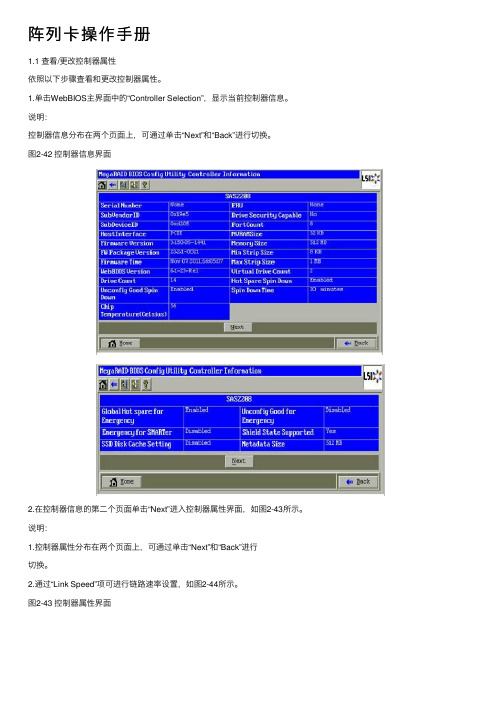
阵列卡操作⼿册1.1 查看/更改控制器属性依照以下步骤查看和更改控制器属性。
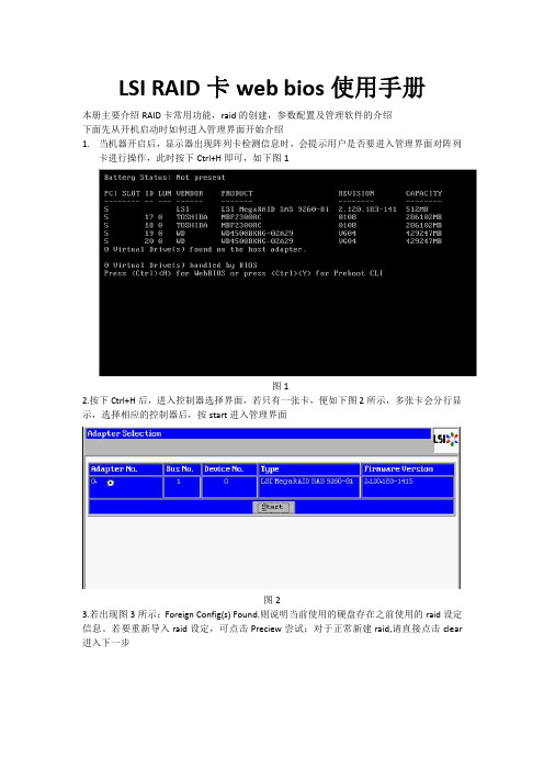
1.单击WebBIOS主界⾯中的“Controller Selection”,显⽰当前控制器信息。
说明:控制器信息分布在两个页⾯上,可通过单击“Next”和“Back”进⾏切换。
图2-42 控制器信息界⾯2.在控制器信息的第⼆个页⾯单击“Next”进⼊控制器属性界⾯,如图2-43所⽰。
说明:1.控制器属性分布在两个页⾯上,可通过单击“Next”和“Back”进⾏切换。
2.通过“Link Speed”项可进⾏链路速率设置,如图2-44所⽰。
图2-43 控制器属性界⾯图2-44 设置链路速率对控制器属性进⾏设置后,可以单击“Submit”保存设置,或单击“Reset”返回默认值。
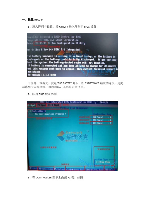
1.2 查看/更改虚拟磁盘属性1.单击WebBIOS主界⾯中的“Virtual Drives”进⼊虚拟磁盘选项界⾯,如图2-45所⽰。
图2-45 虚拟磁盘选项界⾯选择“Properties”进⼊虚拟磁盘属性界⾯,如图2-46所⽰。
图2-46 虚拟磁盘属性界⾯1.在“Properties”信息框中列出了虚拟磁盘的RAID等级、状态、容量、条带尺⼨等信息。
2.在“Policies”信息框中类列出了存储配置创建时设定的虚拟磁盘配置策略。
3.在“Operations”信息框中列出了允许对虚拟磁盘进⾏的操作。
在“Operations”信息框中选择要执⾏的操作,单击“Go”执⾏。
具体选择项介绍如下:注意:请在更改虚拟磁盘配置之前确认虚拟磁盘上的数据已经做好备份。
0.Virtual Drive Erase:擦除虚拟硬盘中所有⽤户⾃定义信息,有Simple、Normal和Thorough三种⽅式。
1.Delete:删除虚拟硬盘。
2.Locate:使能当前虚拟硬盘对应的实际物理硬盘的LED灯,并闪烁。
本功能只在硬盘已被正确安装在硬盘托架中,并⽀持SAFTE时可⽤。
3.Stop Locate:熄灭当前虚拟硬盘对应的实际物理硬盘的LED灯。

一、设置RIAD 01、进入阵列卡设置,按CTRL+R进入阵列卡BIOS设置下面那一堆英文,就是THE BATTEY开头,以ASSISTANCE结束的这段,是提示阵列卡未接电池,可以忽略,不影响正常使用。
2、阵列BIOS默认界面3、在CONTROLLER菜单上面按F2键,如图弹出菜单第一位,选择Create New VD,创建新的阵列显示“Create New VD”(创建新VD)屏幕。
光标位于“RAID Levels”(RAID 级别)选项上。
按键显示RAID 级别。
按下箭头键选择RAID 级别,然后按键。
按键将光标移动到物理磁盘列表。
使用下箭头键高亮度显示某个物理磁盘,并按空格键选择该磁盘。
如果需要,选择其它磁盘。
按键将光标移动到“Basic Settings”(基本设置)框,然后设置虚拟磁盘的大小和名称。
最重要的出来了按键将光标移动到“Advanced Settings”(高级设置)。
如图按空格键激活这些设置,以便可以对其进行更改。
X 将显示在“Advanced Settings”(高级设置)旁边。
这些设置为磁条元大小和读取策略。
您还可以选择高级选项,例如将高速缓存策略强制为回写式、初始化虚拟磁盘及配置专用热备用。
显示窗口时将显示这些参数的默认值。
可以接受默认值或对其进行更改(不建议修改,默认值就可以了)。
执行以下步骤来选择虚拟磁盘参数:按键将光标移动到要更改的参数。
按下箭头键打开参数并向下滚动设置列表。
要更改磁条元大小,请按键高亮度显示“Stripe Element Size”(磁条元大小)。
按键显示磁条元大小列表(8 KB、16 KB、32 KB、64 KB 和128 KB),然后按下箭头键高亮度显示某个选项并按键。
默认推荐选择64K如果需要,按键将光标移动到“Read Policy”(读取策略),以对其进行更改。
按键显示选项,即“Read Ahd”(预读)、“No Read”(非预读)或“Adaptive”(自适应),然后按下箭头键高亮度显示某个选项并按键。
操作设定1. quick logical drive install (快速建立逻辑磁盘)此选项只能够在磁盘阵列还未建立任何logical drive/volume (逻辑磁盘/卷册)时执行,在执行后,控制器将会自动把所有连接的硬盘机建立成一个logical drive,并列出其可建立的层级(依硬盘数的不同而有所改变),且将会自动以lun 0 map 至第一个host channel(主机信道)。
2. view and edit logical drive (检示及设定逻辑磁盘)此选项可用来查看目前逻辑磁盘之设定及状态,亦可针对逻辑磁盘进行建立、切割、重建等等之控制。
若还未建立任何的逻辑磁盘,选单将会是以下的形式:若先前已成功建立逻辑磁盘,则控制器将会显示出目前逻辑磁盘之状态,并可以针对逻辑磁盘再加以设定,如下图:逻辑磁盘状态说明:logical drive: 逻辑磁盘的代号。
raid level: 逻辑磁盘中使用的raid 型态。
drive numbers: 逻辑磁盘中scsi 硬盘的数目logical drive status:xxxxmb 逻辑磁盘的容量。
sb=x 逻辑磁盘中的备用磁盘,它的数量= local spare drives+globaspare drives。
xxxxmb initing 逻辑磁盘现在正在初始化。
xxxxmb invalid the logical drive has been created with "optimization for sequentiali/o", but the current setting is "optimization for random i/o." orthe logical drive has been created with "optimization for randomi/o," but the current setting is "optimization for sequential i/o."xxxxmb gd sb=x 逻辑磁盘正处于正常状态。
M E R C U R Y E L I T E P R O Assembly Manual & User GuideINTRODUCTION (1)1.1 MINIMUM SYSTEM REQUIREMENTS1.1.1 Apple Mac Requirements 1.1.2 PC Requirements 1.1.3 Supported Hard Drives1.2 PACKAGE CONTENTS 1.3 ABOUT THIS MANUAL 1.4 REAR VIEW1.4.1 Connection1.5 LED INDICATORDEVICE SETUP (3)2.1 QUICK START 2.2 ASSEMBLYSUPPORT RESOURCES (7)3.1 FORMATTING3.2 UNMOUNTING DRIVES 3.3 TROUBLESHOOTING 3.4 ABOUT DATA BACKUP 3.5 ONLINE RESOURCES3.6 CONTACTING TECHNICAL SUPPORTTABLE OF CONTENTS1.1.3 Supported Hard Drives Any 3.5” SATA hard drive1.3 ABOUT THIS MANUALThe images and descriptions may vary slightly between this manual and the unit shipped. Functions and features may change depending on the firmware version. Please visit the product web page for the most recent product specifications.1.1.1 Apple Mac Requirements eSATA: OS X 10.3 or later FireWire: OS X 10.3 or laterUSB 3.1 Gen 1 (backwards compatible to USB 2.0): OS X 10.6 or later 1.1.2 PC RequirementseSATA: Windows® XP or later FireWire: Windows XP or laterUSB 3.1 Gen 1 (backwards compatible to USB 2.0): Windows XP or later1.1 MINIMUM SYSTEM REQUIREMENTS1.2 PACKAGE CONTENTSFireWire 800(1394b) cableeSATA cableUSB 3.1 Gen 1 (A to Standard-B) cable Mercury Elite Pro (with vertical stand)Power supply andpower cableINTRODUCTION1.4 REAR VIEW1.4.1 ConnectionPlug the power supply into a power outlet and then into the Mercury Elite Pro. Next, connect the USB 3.1 Gen 1, FireWire 800, or eSATA cable into the drive and the corresponding port on your computer. USAGE NOTES• If you connect the Mercury Elite Pro to its power source and turn the unit on without connecting it to a computer, the drive will temporarily spin up and then spin back down when a data connection is not detected. • Only one interface (FireWire 800, USB 3.1 Gen 1, or eSATA) at a time can be used.• For the safe removal of your drive and to ensure that no data is lost, always unmount the drive from your operating system before powering off the Mercury Elite Pro. •In order for the computer to access volumes larger than 2TB, the operating system needs to support large volumes (e.g., Windows Vista or OS X 10.4 and above).1.5 LED INDICATORThe Mercury Elite Pro has a blue LED at the front of the enclosure. The LED emits a solid light when the unit is powered on, and a flashing light during hard drive activity.2.1 QUICK STARTTo format this drive for Mac OS X (OS 10.4 and later) or Windows (XP and later), follow the steps below. If you installed your own drive, please use the formatting method you are most familiar with or check Section 3.1 for a link to OWC’s online formatting tips.1. Plug in the power supply then connect the Mercury Elite Pro to your computer using the proper cable. If you prefer to use a different formatting utility, do so at this time and skip the rest of these instructions.2. Your drive will show up as “OWC SETUP”. Open your drive to view its contents.3. D ouble-click the OWC Drive Guide application.4. F ollow the simple on-screen instructions to complete the formatting process.5. O nce the formatting is finished the drive is ready to use.2.2 ASSEMBLYNOTICE: The following assembly instructions are written for users who purchased the Mercury Elite Pro as an empty enclosure. The instructions show how to open the Mercury Elite Pro in order to install a drive. If you purchased the Mercury Elite Pro with a drive already installed, opening the Mercury Elite Pro before the expiration of the original warranty will VOID the warranty. If you wish to remove or replace a drive after the expiration of the original warranty, you may do so at that time.1. Remove the Mercury Elite Pro from the retail box and the protective plastic bag.Set the Mercury Elite Pro on its side and look at the bottom of the enclosure. Usea Phillips screwdriver to remove the two screws, circled below in red.DEVICE SETUP2. Once the two screws are removed, slide the inner chassis out the front of the outer case, as shown below. Start by pushing on the back of the inner chassis, then when you are able to grip the front grill of the inner chassis, pull it out the rest of the way.3. When removed from the outer case, the inner chassis will appear as shown below. Remove the packet of screws and use them as directed later in the assembly instructions.4. To install the hard drive, slide it into the black SATA connector inside the Mercury Elite Pro. You may need to move the blue and black LED cables to the side in order to make room for the hard drive. Make sure the drive is firmly seated before proceeding.5. Using the four screws from the packet you removed from the inner chassis, fasten the hard drive to the inner chassis. There are two screw holes on each side of the inner chassis, circled below in red.6. Slide the inner chassis back into the outer case, as shown below.7. Once the front grill of the inner chassis sits flush with the edge of the outer case, turn the Mercury Elite Pro on its side. Use the two smaller screws you removed in Step 1, and refasten the outer case to the inner chassis.3.1 FORMATTINGFor formatting information, including instructions on how to format your OWC M ercury Elite Pro for Mac or Windows, go to: /format3.2 UNMOUNTING DRIVESTo properly unmount any connected drive from your computer, try the options below.OS X:There are several methods to unmount disks with OS X systems. You can drag the icon for the disk you wish to unmount to the trash can, or right-click the disk icon on the desktop, then click “Eject”. You can also eject the disk in the sidebar of a Finder window, or by selecting the drive icon on the Desktop then pressing Command-E.Windows:1. Go to the System Tray (located in the lower right corner of your screen). Click on the “Eject” icon (a small green arrow over a hardware image).2. A message will appear, detailing the devices that the “Eject” icon controls, i.e., “Safely remove...” Click on this prompt.3. Y ou will then see a message that says, “Safe to Remove Hardware.” It is now safe to disconnect the Mercury Elite Pro from the computer.3.3 TROUBLESHOOTINGBegin your troubleshooting by verifying that the power cable is connected to the Mercury Elite Pro and to a power source. If the power cable is connected to a power strip, make sure that the power switch on the strip is turned on.Then, simply verify that both ends of your cables are properly plugged into the computer and the Mercury Elite Pro. If the Mercury Elite Pro is still not working properly, try connecting to another interface such as the USB connection and see if the device works properly. You can also connect the Mercury Elite Pro to a different computer. If problems persist, seeSection 3.6to contact OWC technical support.SUPPORT RESOURCES3.4 ABOUT DATA BACKUPTo ensure that your files are protected and to prevent data loss, we strongly suggest that you keep two copies of your data: one copy on your OWC Mercury Elite Pro and a second copy on your internal drive or another storage medium, such as an optical backup, or on a second external storage unit. Any data loss or corruption while using the Mercury Elite Pro is the sole responsibility of the user, and under no circumstances may OWC, its parents, partners, and affiliates be held liable for loss of the use of data including compensation of any kind or recovery of the data.3.5 ONLINE RESOURCESData Migration:For a step-by-step walkthrough of our recommended method for migrating your data from an old drive to a new one, go to:/support/data-transferFAQs:Access our online collection of frequently asked questions for this and other products at: /support/faq3.6 CONTACTING TECHNICAL SUPPORT8AM - 8PM (CT) Monday - Friday9AM - 4PM (CT) Saturday(866) 692-7100 (North America)+1 (815) 338-4751 (International)Live chat is available during normal business hours at:/support/Email support is available at:/support/Changes:The material in this document is for information purposes only and subject to change without notice. While reasonable efforts have been made in the preparation of this document to assure its accuracy, OWC and its officers and employees assume no liability resulting from errors or omissions in this document, or from the use of the information contained herein. OWC reserves the right to make changes or revisions in the product design or the product manual without reservation and without obligation to notify any person of such revisions and changes.FCC Statement:Warning! Modifications not authorized by the manufacturer may void the user’s authority to operate this device.NOTE: This equipment has been tested and found to comply with the limits for a Class A digital device, pursuant to Part 15 of the FCC Rules. These limits are designed to provide reasonable protection against harmful interference when the equipment is operated in a commercial environment. This equipment generates, uses, and can radiate radio frequency energy and, if not installed and used in accordance with the instruction manual, may cause harmful interference with radio communications. Operation of this equipment in a residential area is likely to cause harmful interference, in which case the user will be required to correct the interference at his own expense.NOTE: This equipment has been tested and found to comply with the limits for a Class B digital device, pursuant to Part 15 of the FCC Rules. These limits are designed to provide reasonable protection against harmful interference in a residential installation. This equipment generates, uses and can radiate radio frequency energy and, if not installed and used in accordance with the instructions, may cause harmful interference to radio communications. However, there is no guarantee that interference will not occur in a particular installation. If this equipment does cause harmful interference with radio or television reception, which can be determined by turning the equipment off and on, the user is encouraged to try to correct the interference by one or more of the following measures:• Reorient or relocate the receiving antenna.• Increase the separation between the equipment and receiver.• Connect the equipment to an outlet on a circuit different from that to which the receiver is connected.Health And Safety Precautions:• Use proper anti-static precautions while performing the installation of your hard drives into this drive enclosure. Failure to do so can cause damage to your drive mechanisms and/or the hard drive enclosure.• Read this user guide carefully and follow the correct procedures when setting up the device.• Do not attempt to disassemble or modify the device. To avoid any risk of electrical shock, fire, short-circuiting or dangerous emissions, never insert any metallic object into the device. If it appears to be malfunctioning, contact OWC technical support.• Never expose your device to rain, or use it near water or in damp or wet conditions. Never place objects containing liquids on the drive, as they may spill into its openings. Doing so increases the risk of electrical shock, short-circuiting, fire or personal injury.Copyright 2016 OWC. All Rights Reserved. OWC’s Limited Warranty is not transferable and subject to limitations.General Use Precautions:• To avoid damage, do not expose the device to temperatures outside the range of 5° C to 40° C (41° F to 104° F).• Always unplug the device from the electrical outlet if there is a risk of lightning or if it will be unused for an extended period of time. Otherwise, there is an increased risk of electrical shock, short-circuiting or fire.• Do not use the device near other electrical appliances such as televisions, radios or speakers. Doing so may cause interference which will adversely affect the operation of the other products.• Do not place the device near sources of magnetic interference, such as computer displays, televisions or speakers. Magnetic interference can affect the operation and stability of hard drives.• Do not place heavy objects on top of the device.• Protect your device from excessive exposure to dust during use or storage. Dust can build up inside the device, increasing the risk of damage or malfunction.• Do not block any ventilation openings on the device. These help to keep the device cool during operation. Blocking the ventilation openings may cause damage to the device and cause an increased risk of short-circuiting or fire.•For up-to-date product and warranty information, please visit the product web page.Copyrights and Trademarks:No part of this publication may be reproduced, stored in a retrieval system, or transmitted in any form or by any means, electronic, mechanical, photocopying, recording or otherwise, without the prior written consent of OWC.© 2016 OWC. All rights reserved.OWC is a trademark of New Concepts Development Corporation, registered in the U.S. Patent and Trademark Office and/or in Canada. The OWC logo is a trademark of New Concepts Development Corporation. Apple, FireWire, Mac, and OS X are trademarks of Apple Inc., registered in the U.S. and other countries. Windows is a registered trademark of M icrosoft Corporation in the U.S. and other countries. Other marks may be the trademark or registered trademark property of their owners.OWCMANMEPU3FWESR4 04/12/16 DM。
LSI 8708 SAS用户手册MEGA RAID WEB1、按F2进入BIOS,将Quiet Boot :设置为[Disabled],保存后重启。
根据提示按<Ctrl>+<H>进入WEB 主菜单,如图1-2图1图22、按回车《Enter》或者点接《start》进入卡的主菜单如图3,右边显示9个主菜单,左边显示所有硬盘的信息。
3、主菜单介绍:图33.1 点接Adapter Properties(查看卡属性)—>点接Next(下一步),图4—5图4图5 3.2 点接Scan Devices(查看设备驱动)图6图6 3.3 点接Virtual Disks(虚拟磁盘)图7图7 3.4 点接Physical Drives(物理驱动器)查看,图8图8 3.5 点接Configuration Wizard(配置向导)图9图93.6 点接Adapter Selection(卡选择)图10图103.7 Physical View(物理磁盘浏览)3.8 Events(日志查看)3.8 Exit(退出)4、配置RAID4.1点接Configuration Wizard(配置向导)—>选择Custom Configuration(自定义配置)—>Next(下一步)。
图114.2 按住《Ctrl》键用鼠标选择你需要的硬盘,然后点接Add to Array(添加到阵列),图12—14所示图12图144.3同样按住《Ctrl》键用鼠标选择Disk Groups下面你需要的硬盘,然后点接Accept DG(接受磁盘阵列)—>点接Next(下一步),图15—17所示图16图174.4 点接 Add to SPAN(添加到SPAN中)—>点接Next(下一步),图18-19图18图194.5 在RAID Level(RAID级别)处选择你需要的RAID,这里以RAID5为例,,在Select Size(选择输入容量),输入208854。
右边分别显示出RAID 0 、RAID10 、RAID5 、RAID 6的容量,相应的RAID 级别输入右边对应的容量。
然后点接 Accept (接受)—>点接Next(下一步)—>Accept(接受),图20—22所示图20图21图224.6 问是否 Save this Cconfiguration(保存这个配置),点接Yes(是)—>是否需要(初始化)Initialize(所有阵列上的数据都将丢失)点接Yes(是)—>点接Back(返回),这样RAID 5已经做好。
图23—26所示。
图23图24图25图265、修复(Rebuild)阵列5.1 如果RAID5阵列中有一个硬盘掉线或者坏,这时阵列卡会发出报警声,进RAID卡界面后你会看到右边物理驱动器下面显示红色1:3(就是第四个硬盘丢失),Virtual Drives(虚拟驱动器)下面VD0显示Degraded(降级状态),如图27如图275.2 在机器上找到对应的硬盘盘位,拔下坏的硬盘,换上新硬盘后,阵列会自动修复(Rebuild),如果换上的新硬盘里面的有数据,阵列不会自动修复,那就要把这个硬盘做成热备(HotSpare),图28,右边Physical Drives(物理驱动器)下面显示黑色为新换上的硬盘。
图285.3 点接右边Physical Drives(物理驱动器)下面显示黑色的那个硬盘,图29所示图295.4 选择上Make Unconf Good(使未知的硬盘变好)—>点接Go(继续),图30图305.5 选择上 Make Glocal HSP(使这个硬盘为全球的热备),然后点接Go(继续)—>点接Back(返回),右边Physical Drives(物理驱动器)下面的硬盘由黑色变为了蓝色。
图31图315.6 点接主菜单里的点接Scan Devices(查看设备驱动)—>点接Preview(查看),这时你会在左边看到新换上的硬盘在修复(Rebuild),图32-33所示图33图335.6 点接Import(输入)后,如图34,在右边你能看见硬盘在修复(Rebuild)图345.7 直接点接右边正在修复的这个硬盘,你会看到RAID修复的进度,直到修复到100%,这时阵列卡报警声消失。
图35图356、删除RAID6.1 点接Configuration Wizard(配置向导)—>选择Clear Configuration(清楚配置)—>点接Next(下一步),图36图366.2 这时候会出现如图37所示,提示阵列的所有数据将会丢失,如果你不需要数据,就点接Yes(是),RAID将被删除,图38。
图37图38M ega RAID SAS (LS8708)WEB管理界面(Windows)一、安装WEB管理软件,1.1首先把WEB管理软件考入你的电脑,直接双接Setup.exe这个文件,一直点接Next(下一步),直到安装完成,这时候会在你的桌面上多出一个Mega RAID这个图面。
图1—5所示图1图2图3图4图51.2 双接这个Mega RAID这个图标,如图6,输入用户用名和密码(就是本机的用户名和密码)进入RAID卡的管理界面。
图6二、主菜单介绍(1)File Menu(文件菜单)(2)Operations Menu(操作菜单)(3)Group Operations Menu(群运算菜单)是选择包括检测连接,显示进程和初始化(4)Tools Menu(工具菜单)(5)Log Menu(日志菜单)(6)Help Menu(帮助菜单)Physical/Logical View Panel点接Physical(物理菜单),左边显示阵列卡以及硬盘数量,右边为显示阵列卡以及硬盘的属性以及控制台和图形(Properties/Operations /Graphical Panels)图7-9图7图8图92、点接Logical(逻辑菜单)左边显示阵列卡、RAID5以及硬盘数量,右边为显示阵列卡、RAID5以及硬盘的属性以及控制台和图形(Properties/Operations / Graphical Panels)2.1 点接左边Mega RAID SAS。
(阵列卡),然后在点接右边的Properties/Operations Panels),可以查看属性以及控制台。
图10—11图10图112.2 点接左边的虚拟磁盘0(Virtual Disk 0:RAID5),然后点接右边的(Properties/Operations /Graphical Panels)RAID5的属性以及控制台和图形,如图12-14图12图13图14三、配置RAID3.1 用鼠标右键点接Mega RAID SAS(阵列卡)—>Configuration(配置)—>Configuration Wizard(配置向导),图15图153.2 选择Manual Configuration(手动配置)—>点接Next(下一步),图16图163.3 在左边方框里选择你需要配置的硬盘,点接Add(添加)到左边阵列中,图17图173.4 点接Accept(接受)—>点接Next(下一步)图18—19图183.5 这里以一个硬盘为例,在RAID Level(RAID 级别)选择你要做的RAID级别,只能选择RAID 0,在V olume Name(卷标名字)输入RAID 0,然后点接Accept(接受),图20图203.6 点接Next(下一步)—>点接Finish(完成),图21—22所示,图213.7 在Logical下面可以看到刚配置的Virtual Disk 1:RAID0,如图23图23四、删除RAID4.1 鼠标右键点接Virtual Disk 1:RAID0—>点接Delete Virtual Disk(删除虚拟磁盘)图244.2 这时会出现一个Warning(警告),你确定要删除这个虚拟磁盘吗?如果你确定的话,就选择Yes(是),如图25图25五、修复(Rebuild)RAID5.1当阵列中有一个硬盘坏或者丢失后,RAID卡会发出报警声音,通过管理软件查看到逻辑(Logical)下面的Virtual Disk 0变为黄色。
并且通过管理软件查看是那一个磁盘,然后换上新硬盘后阵列会自动修复(Rebuild)。
如果换上去的新硬盘有数据并且不自动修复时,在右边Physical(物理选项)下面看到新换上的硬盘是红色的,这时要把这个硬盘做成Hotspare(热备),首先选上红色的这个磁盘,然后点接右边Operations(控制选项)—>选上Change to Unconfigured Good(改变成未知的好磁盘)—>点接Go(继续)。
如图26图265.2 选择上Make Global Hotspare(变为全球的热备状态),再最右边选上WithAffinity(有关系的)—>点接Go(继续),这时RAID就会修复(Rebuild)了。
如图27图275.2这时点接最上面菜单里的Group Operrations(群操作)—Group ShowProgress(查看群进度),也就是Rebuild进度,如图28,直到100%完毕,报警声消失,图28。