BGP MPLS VPN配置实例
- 格式:docx
- 大小:314.68 KB
- 文档页数:14

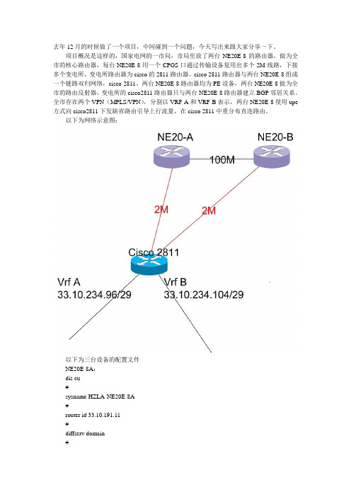
实验二 MPLS VPN的实现一、实验目的该实验通过MPLS VPN的数据配置,使学生掌握路由器相关接口的IP地址设置、路由协议的配置以及MPLS VPN的完整的创建过程, 从而加深对IP网络的IP编址、路由协议以及MPLS的相关理论的理解。
二、实验内容利用网络模拟器GNS3模拟Cisco的实验环境,搭建IP网络,完成CE、PE和P路由器上的数据配置, 使属于同一VPN的两个路由器能够互通。
三、实验设备1.硬件:PC机。
2.软件:①网络模拟器 GNS3-0.8.6-all-in-one②终端仿真程序 SecureCRT6.7③Cisco IOS文件 C3640-JK9O3S-M-12.4(7a).BIN四、实验步骤及要求1.按图1创建网络拓扑结构并把该拓扑结构记录在实验报告中。
图1 MPLS VPN实验的拓扑结构2.配置各个路由器相关接口的IP地址并记录在实验报告中。
3.配置骨干网络内路由协议。
4.配置骨干网络内MPLS协议。
5.配置普通BGP。
6.在PE上创建VRF。
7.创建MP-BGP。
8.配置用户端路由协议。
9.查看VRF路由、CE路由和客户端路由,并将R1、R4和R6的路由显示结果及分析记录在实验报告中。
10.测试用户间通信并跟踪路由,将结果记录在实验报告中。
五、实验报告实验报告的内容:包括实验名称;实验目的;实验内容(实验操作的步骤或实验过程,要求步骤完整);实验结果(实验结果分析,实验中遇到的问题及解决方法)。
实验报告的要求:实验报告以纸质文档形式递交。
实验报告要书写规范、文字简练、语句通顺、图表清晰。
六、实验思考题1.简述三层MPLS VPN的基本原理。
2.简述三层MPLS VPN中PE路由器的配置步骤。
3.MPLS VPN中P路由器转发的数据包有两层标签,说明这两层标签分别是由什么协议分配的。
4.简述MPLS VPN中RT和RD的作用。

eNSP实验:BGP-MPLS-VPNBGP MPLS VPN 配置实验目录1网络拓扑 (5)2配置文件 (5)2.1PE1的相关配置52.1.1在MPLS骨干网上配置IGP协议,实现骨干网PE和P的互通 (5)2.1.2在PE1上配置与PE2、P的IBGP62.1.3MPLS骨干网上配置MPLS基本能力和MPLS LDP,建立LDP LSP (7)2.1.4在PE设备上配置VPN实例,将CE接入PE (7)2.1.5在PE与CE之间建立EBGP对等体,引入VPN路由 (9)2.2P的相关配置102.2.1在MPLS骨干网上配置IGP协议,实现骨干网PE和P的互通 (10)2.2.2P上配置与PE1、PE2的IBGP112.2.3MPLS骨干网上配置MPLS基本能力和MPLS LDP,建立LDP LSP (12)2.2.4 (xxx)错误!未定义书签。
2.3PE2相关配置 142.3.1在MPLS骨干网上配置IGP协议,实现骨干网PE和P的互通 (14)2.3.2在PE2上配置与P、PE1的IBGP152.3.3MPLS骨干网上配置MPLS基本能力和MPLS LDP,建立LDP LSP (15)2.3.4在PE设备上配置VPN实例,将CE接入PE (16)2.3.5PE与CE之间建立EBGP对等体,引入VPN路由 (17)2.4CE1的相关配置 182.5CE2的相关配置 192.6CE3的相关配置192.7CE4的相关配置203实验结果: (20)3.1PE1 vpn 路由表203.2P路由表213.3Ping:相同VPN之间可以通,不同VPN之间不通, (23)1网络拓扑2配置文件2.1PE1的相关配置2.1.1在MPLS骨干网上配置IGP-OSPF协议,实现骨干网PE和P的互通#Sysna PE1ospf 1area 0.0.0.0network 10.0.0.0 0.0.0.3network 1.1.1.1 0.0.0.0 (igp-ospf)#interface LoopBack0ip address 1.1.1.1 255.255.255.255ospf enable 1 area 0.0.0.0 端口使能ospf)network 10.0.0.0 255.255.255.252peer 2.2.2.2 enable Array peer 3.3.3.3 enable (宣告网络)#2.1.3MPLS骨干网上配置MPLS基本能力和MPLS LDP,建立LDP LSP#mpls lsr-id 1.1.1.1 mplslsp-trigger allmpls ldp(使能mpls)#interface Ethernet0/0/0mplsmpls ldp(端口使能mpls)#2.1.4在PE设备上配置VPN实例,将CE接入PEip vpn-instance VPN1创建并进入VPN实例视图ipv4-familyroute-distinguisher 100:1 为vpn-instance创建RDvpn-target 111:1 export-extcommunity 为vpn-instance创建vpn-target扩展团体vpn-target 111:1 import-extcommunity (配置VPN1)#ip vpn-instance VPN2ipv4-familyroute-distinguisher 200:1vpn-target 222:1 export-extcommunityvpn-target 222:1 import-extcommunity (配置VPN2)#interface Ethernet0/0/1ip binding vpn-instance VPN1 将接口与vpn-instance关联ip address 10.0.0.13 255.255.255.252 (端口绑定VPN)interface GigabitEthernet0/0/0ip binding vpn-instance VPN2ip address 10.0.0.9 255.255.255.252 (端口绑定VPN)#2.1.5在PE与CE之间建立EBGP对等体,引入VPN路由#bgp 65115ipv4-family vpnv4进入MBGP的VPNv4地址族视图policy vpn-targetpeer 2.2.2.2 enable激活MBGP对等体peer 3.3.3.3 enable(建立邻居关系)#ipv4-family vpn-instance VPN1进入BGP的VPN地址族视图import-route directimport-route static (配置 vpn路由)ipv4-family vpn-instance VPN2import-route directimport-route static (配置 vpn路由)#ip route-static vpn-instance VPN1 0.0.0.00.0.0.0 10.0.0.14ip route-static vpn-instance VPN2 0.0.0.00.0.0.0 10.0.0.10 (配置vpn静态路由:PE和CE间通过静态路由链接的配置)#2.2P的相关配置2.2.1在MPLS骨干网上配置IGP协议,实现骨干网PE和P的互通#sysna Pospf 1area 0.0.0.0network 10.0.0.0 0.0.0.3network 10.0.0.4 0.0.0.3network 2.2.2.2 0.0.0.0 (igp-ospf)#interface LoopBack0ip address 2.2.2.2 255.255.255.255ospf enable 1 area 0.0.0.0 (端口使能ospf)interface Ethernet0/0/0ip address 10.0.0.2 255.255.255.252ospf enable 1 area 0.0.0.0 (端口使能ospf)interface Ethernet0/0/1ip address 10.0.0.5 255.255.255.252ospf enable 1 area 0.0.0.0 (端口使能ospf)#2.2.2P上配置与PE1、PE2的IBGP#bgp 65115router-id 2.2.2.2peer 1.1.1.1 as-number 65115peer 1.1.1.1 connect-interfaceEthernet0/0/0peer 3.3.3.3 as-number 65115peer 3.3.3.3 connect-interfaceEthernet0/0/1 (配置bgp)#ipv4-family unicastundo synchronizationnetwork 2.2.2.2 255.255.255.255network 10.0.0.0 255.255.255.252network 10.0.0.4 255.255.255.252peer 1.1.1.1 enablepeer 3.3.3.3 enable (宣告网络)#2.2.3MPLS骨干网上配置MPLS基本能力和MPLS LDP,建立LDP LSP#mpls lsr-id 2.2.2.2mplslsp-trigger allmpls ldp(使能mpls)#interface Ethernet0/0/0mplsmpls ldp (端口使能mpls)#interface Ethernet0/0/1mplsmpls ldp (端口使能mpls)#2.2.4建立P与PE1、PE2的邻居关系#bgp 65115ipv4-family vpnv4policy vpn-targetpeer 1.1.1.1 enablepeer 3.3.3.3 enable (建立邻居关系)#2.3PE2相关配置和PE1类似2.3.1在MPLS骨干网上配置IGP协议,实现骨干网PE和P的互通#Sysna PE2ospf 1area 0.0.0.0network 10.0.0.4 0.0.0.3network 3.3.3.3 0.0.0.0 (igp-ospf)#interface LoopBack0ip address 3.3.3.3 255.255.255.255ospf enable 1 area 0.0.0.0 端口使能ospf)interface Ethernet0/0/0ip address 10.0.0.6 255.255.255.252ospf enable 1 area 0.0.0.0 (端口使能ospf)#2.3.2在PE2上配置与P、PE1的IBGP#bgp 65115router-id 3.3.3.3peer 1.1.1.1 as-number 65115peer 1.1.1.1 connect-interface LoopBack0(配置bgp)ipv4-family unicastundo synchronizationnetwork 3.3.3.3 255.255.255.255network 10.0.0.4 255.255.255.252peer 2.2.2.2 enablepeer 1.1.1.1 enable (宣告网络)#2.3.3MPLS骨干网上配置MPLS基本能力和MPLS LDP,建立LDP LSP#mpls lsr-id 3.3.3.3mplslsp-trigger allmpls ldp(使能mpls)#interface Ethernet0/0/0mplsmpls ldp(端口使能mpls)#2.3.4在PE设备上配置VPN实例,将CE接入PE#ip vpn-instance VPN1ipv4-familyroute-distinguisher 100:1vpn-target 111:1 export-extcommunityvpn-target 111:1 import-extcommunity# (配置VPN1)ip vpn-instance VPN2ipv4-familyroute-distinguisher 200:1vpn-target 222:1 export-extcommunityvpn-target 222:1 import-extcommunity(配置VPN2)#interface Ethernet0/0/1ip binding vpn-instance VPN1ip address 10.0.0.17 255.255.255.252 (端口绑定VPN)interface GigabitEthernet0/0/0ip binding vpn-instance VPN2ip address 10.0.0.21 255.255.255.252 (端口绑定VPN)#2.3.5PE与CE之间建立EBGP对等体,引入VPN路由bgp 65115ipv4-family vpnv4policy vpn-targetpeer 2.2.2.2 enablepeer 1.1.1.1 enable(建立邻居关系)#ipv4-family vpn-instance VPN1import-route directimport-route static (配置 vpn路由)ipv4-family vpn-instance VPN2import-route directimport-route static (配置 vpn路由)#ip route-static vpn-instance VPN1 0.0.0.0 0.0.0.0 10.0.0.18ip route-static vpn-instance VPN2 0.0.0.0 0.0.0.0 10.0.0.22#(配置vpn静态路由)2.4CE1的相关配置#Sysn CE1interface Ethernet0/0/0ip address 10.0.0.10 255.255.255.252ip route-static 0.0.0.0 0.0.0.0 10.0.0.9(配置静态路由)#save2.5CE2的相关配置#Sysn CE2interface Ethernet0/0/0ip address 10.0.0.14 255.255.255.252 ip route-static 0.0.0.0 0.0.0.0 10.0.0.13 #2.6CE3的相关配置#Sysn CE3interface Ethernet 0/0/0ip address 10.0.0.18 255.255.255.252 ip route-static 0.0.0.0 0.0.0.0 10.0.0.17 #2.7CE4的相关配置#SysSysn CE4interface Ethernet 0/0/0ip address 10.0.0.22 255.255.255.252 ip route-static 0.0.0.0 0.0.0.0 10.0.0.21 #3实验结果:3.1PE1 vpn 路由表[PE1]disp ip rout[PE1]disp ip routing-tableRoute Flags: R - relay, D - download to fib------------------------------------------------------------------------------Routing Tables: PublicDestinations : 8 Routes : 8Destination/Mask Proto Pre Cost Flags NextHop Interface1.1.1.1/32 Direct 0 0 D 127.0.0.1 LoopBack02.2.2.2/32 OSPF 10 1 D 10.0.0.2 Ethernet0/0/03.3.3.3/32 OSPF 10 2 D 10.0.0.2 Ethernet0/0/010.0.0.0/30 Direct 0 0 D 10.0.0.1 Ethernet0/0/010.0.0.1/32 Direct 0 0 D 127.0.0.1 Ethernet0/0/010.0.0.4/30 OSPF 10 2 D 10.0.0.2 Ethernet0/0/0127.0.0.0/8 Direct 0 0 D 127.0.0.1 InLoopBack0127.0.0.1/32 Direct 0 0 D 127.0.0.1 InLoopBack0[PE1]disp ip routing-table vp[PE1]disp ip routing-table vpn-instance ?STRING<1-31> VPN instance name[PE1]disp ip routing-table vpn-instance VPN1Route Flags: R - relay, D - download to fib------------------------------------------------------------------------------Routing Tables: VPN1Destinations : 4 Routes : 4Destination/Mask Proto Pre Cost Flags NextHop Interface0.0.0.0/0 Static 60 0 RD 10.0.0.14 Ethernet0/0/110.0.0.12/30 Direct 0 0 D 10.0.0.13 Ethernet0/0/110.0.0.13/32 Direct 0 0 D 127.0.0.1 Ethernet0/0/110.0.0.16/30 IBGP 255 0 RD 3.3.3.3 Ethernet0/0/0[PE1][PE1]disp ip routing-table vpn-instance VPN2Route Flags: R - relay, D - download to fib------------------------------------------------------------------------------Routing Tables: VPN2Destinations : 4 Routes : 4Destination/Mask Proto Pre Cost Flags NextHop Interface0.0.0.0/0 Static 60 0 RD 10.0.0.10GigabitEthernet0/0/010.0.0.8/30 Direct 0 0 D 10.0.0.9GigabitEthernet0/0/010.0.0.9/32 Direct 0 0 D 127.0.0.1GigabitEthernet0/0/010.0.0.20/30 IBGP 255 0 RD 3.3.3.3 Ethernet0/0/0 [PE1]3.2P路由表<P>disp ip routingRoute Flags: R - relay, D - download to fib------------------------------------------------------------------------------ Routing Tables: PublicDestinations : 9 Routes : 9Destination/Mask Proto Pre Cost Flags NextHop Interface1.1.1.1/32 OSPF 10 1 D 10.0.0.1 Ethernet0/0/02.2.2.2/32 Direct 0 0 D 127.0.0.1 LoopBack03.3.3.3/32 OSPF 10 1 D 10.0.0.6 Ethernet0/0/110.0.0.0/30 Direct 0 0 D 10.0.0.2 Ethernet0/0/010.0.0.2/32 Direct 0 0 D 127.0.0.1 Ethernet0/0/010.0.0.4/30 Direct 0 0 D 10.0.0.5 Ethernet0/0/110.0.0.5/32 Direct 0 0 D 127.0.0.1 Ethernet0/0/1127.0.0.0/8 Direct 0 0 D 127.0.0.1 InLoopBack0127.0.0.1/32 Direct 0 0 D 127.0.0.1 InLoopBack0PE2 Vpn 路由表<PE2>dis ip routRoute Flags: R - relay, D - download to fib------------------------------------------------------------------------------ Routing Tables: PublicDestinations : 8 Routes : 8Destination/Mask Proto Pre Cost Flags NextHop Interface1.1.1.1/32 OSPF 10 2 D 10.0.0.5 Ethernet0/0/02.2.2.2/32 OSPF 10 1 D 10.0.0.5 Ethernet0/0/03.3.3.3/32 Direct 0 0 D 127.0.0.1 LoopBack010.0.0.0/30 OSPF 10 2 D 10.0.0.5 Ethernet0/0/010.0.0.4/30 Direct 0 0 D 10.0.0.6 Ethernet0/0/010.0.0.6/32 Direct 0 0 D 127.0.0.1 Ethernet0/0/0127.0.0.0/8 Direct 0 0 D 127.0.0.1 InLoopBack0127.0.0.1/32 Direct 0 0 D 127.0.0.1 InLoopBack0<PE2>dis ip rou<PE2>dis ip routing-table vpn-instance VPN1Route Flags: R - relay, D - download to fib------------------------------------------------------------------------------ Routing Tables: VPN1Destinations : 3 Routes : 3Destination/Mask Proto Pre Cost Flags NextHop Interface10.0.0.12/30 IBGP 255 0 RD 1.1.1.1 Ethernet0/0/010.0.0.16/30 Direct 0 0 D 10.0.0.17 Ethernet0/0/110.0.0.17/32 Direct 0 0 D 127.0.0.1 Ethernet0/0/1<PE2>dis ip routing-table vpn-instance VPN2Route Flags: R - relay, D - download to fib------------------------------------------------------------------------------ Routing Tables: VPN2Destinations : 4 Routes : 4Destination/Mask Proto Pre Cost Flags NextHop Interface0.0.0.0/0 Static 60 0 RD 10.0.0.22 GigabitEthernet0/0/0 10.0.0.8/30 IBGP 255 0 RD 1.1.1.1 Ethernet0/0/010.0.0.20/30 Direct 0 0 D 10.0.0.21 GigabitEthernet0/0/0 10.0.0.21/32 Direct 0 0 D 127.0.0.1 GigabitEthernet0/0/0<PE2><P>3.3Ping:相同VPN之间可以通,不同VPN之间不通,CE2-CE4不通<CE2>ping 10.0.0.22PING 10.0.0.22: 56 data bytes, press CTRL_C to breakRequest time outRequest time outRequest time outRequest time outRequest time out--- 10.0.0.22 ping statistics ---5 packet(s) transmitted0 packet(s) received100.00% packet lossCE2-CE3能通<CE2>ping 10.0.0.18PING 10.0.0.18: 56 data bytes, press CTRL_C to breakReply from 10.0.0.18: bytes=56 Sequence=1 ttl=253 time=390 ms Reply from 10.0.0.18: bytes=56 Sequence=2 ttl=253 time=140 ms Reply from 10.0.0.18: bytes=56 Sequence=3 ttl=253 time=140 ms Reply from 10.0.0.18: bytes=56 Sequence=4 ttl=253 time=140 ms Reply from 10.0.0.18: bytes=56 Sequence=5 ttl=253 time=120 ms--- 10.0.0.18 ping statistics ---5 packet(s) transmitted5 packet(s) received0.00% packet lossround-trip min/avg/max = 120/186/390 ms <CE2>。

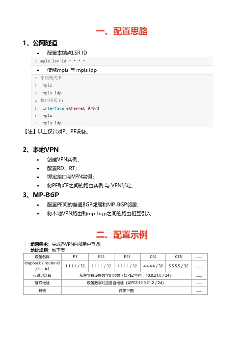
去年12月的时候做了一个项目,中间碰到一个问题,今天写出来跟大家分享一下。
项目概况是这样的,国家电网的一市局,市局里放了两台NE20E-8的路由器,做为全市的核心路由器,每台NE20E-8用一个CPOS口通过传输设备复用出多个2M线路,下接多个变电所,变电所路由器为cisco的2811路由器。
cisco 2811路由器与两台NE20E-8组成一个链路双归网络,cisco 2811、两台NE20E-8路由器均为PE设备,两台NE20E-8做为全市的路由反射器,变电所的cisco2811路由器只与两台NE20E-8路由器建立BGP邻居关系。
全市存在两个VPN(MPLS/VPN),分别以VRF A和VRF B表示,两台NE20E-8使用upe 方式向cisco2811下发缺省路由引导上行流量,在cisco 2811中重分布直连路由。
以下为网络示意图:以下为三台设备的配置文件NE20E-8A:dis cu#sysname HZLA-NE20E-8A#router id 33.10.191.11#diffserv domain#ip vpn-instance realtimeroute-distinguisher 2007:1vpn-target 30033:11 export-extcommunityvpn-target 30033:1 30033:11 30033:13 import-extcommunity #ip vpn-instance nrtroute-distinguisher 2007:2vpn-target 30033:12 export-extcommunityvpn-target 30033:2 30033:12 30033:14 import-extcommunity #mpls lsr-id 33.10.191.11mpls#mpls ldp#controller Cpos3/0/0e1 6 channel-set 0 timeslot-list 1-31#interface Aux0async mode flowlink-protocol ppp#interface Ethernet1/0/0#interface Ethernet1/0/1#interface Ethernet1/0/2#interface Ethernet1/0/3#interface Ethernet1/0/4description LINK_TO_HZ-NE20-8Aip address 33.10.190.6 255.255.255.252mplsmpls ldp#interface Ethernet1/0/5#interface Ethernet1/0/6#interface Ethernet1/0/7#interface Ethernet2/0/0#interface Ethernet2/0/1#interface Ethernet2/0/2description LINK_TO_HZLA-NE20-8Bip address 33.10.190.61 255.255.255.252 mplsmpls ldp#interface Ethernet2/0/3#interface Ethernet2/0/4#interface Ethernet2/0/5#interface Ethernet2/0/6#interface Ethernet2/0/6.100vlan-type dot1q 100description LINK_TO_HZLA-S3328TP-RT ip binding vpn-instance realtimeip address 33.10.190.209 255.255.255.252 #interface Ethernet2/0/6.200vlan-type dot1q 200description realtimeip binding vpn-instance realtimeip address 10.33.177.94 255.255.255.224 vrrp vrid 200 virtual-ip 10.33.177.94#interface Ethernet2/0/7#interface Ethernet4/0/0#interface Ethernet4/0/1#interface Ethernet4/0/2#interface Ethernet4/0/3#interface Ethernet4/0/4#interface Ethernet4/0/5#interface Ethernet4/0/6#interface Ethernet4/0/6.300#interface Ethernet4/0/6.400description nrt#interface Ethernet4/0/7#interface Serial3/0/0/6:0link-protocol pppdescription xiushuiip address 33.10.177.217 255.255.255.252 mplsmpls ldp#interface GigabitEthernet0/0/1#interface GigabitEthernet0/0/2#interface NULL0#interface LoopBack0ip address 33.10.191.11 255.255.255.255 #bgp 30033group 500 internalpeer 500 connect-interface LoopBack0 peer 33.10.191.131 as-number 30033 peer 33.10.191.131 group 500group 300 internalpeer 300 connect-interface LoopBack0 peer 33.10.191.1 as-number 30033peer 33.10.191.1 group 300peer 33.10.191.12 as-number 30033peer 33.10.191.12 group 300#ipv4-family unicastundo synchronizationreflector cluster-id 100.100.100.100peer 300 enablepeer 33.10.191.1 enablepeer 33.10.191.1 group 300peer 33.10.191.12 enablepeer 33.10.191.12 group 300peer 500 enablepeer 500 reflect-clientpeer 33.10.191.131 enablepeer 33.10.191.131 group 500#ipv4-family vpnv4reflector cluster-id 100.100.100.100policy vpn-targetpeer 300 enablepeer 33.10.191.1 enablepeer 33.10.191.1 group 300peer 33.10.191.12 enablepeer 33.10.191.12 group 300peer 500 enablepeer 500 reflect-clientpeer 500 upepeer 500 default-originate vpn-instance realtimepeer 500 default-originate vpn-instance nrtpeer 33.10.191.131 enablepeer 33.10.191.131 group 500#ipv4-family vpn-instance realtimeimport-route directimport-route static#ipv4-family vpn-instance nrtimport-route directimport-route static#aaalocal-user admin password cipher .]@USE=B,53Q=^Q`MAF4<1!! local-user admin service-type telnetlocal-user admin level 15authentication-scheme default#authorization-scheme default#accounting-scheme default#domain default##ospf 1area 0.0.0.21network 33.10.191.11 0.0.0.0network 33.10.190.4 0.0.0.3network 33.10.190.60 0.0.0.3network 33.10.177.216 0.0.0.3#nqa-jitter tag-version 1#snmp-agentsnmp-agent local-engineid 000007DB7F00000100004E8Bsnmp-agent community write Zpepbdc@sjwsnmp-agent community read huaWei8zjepsnmp-agent sys-info version allsnmp-agent target-host trap address udp-domain 10.33.223.178 params securityname huaWei8zjepsnmp-agent target-host trap address udp-domain 10.33.223.179 params securityname huaWei8zjepsnmp-agent trap enable standardsnmp-agent trap source LoopBack0#user-interface con 0user-interface aux 0user-interface vty 0 4authentication-mode aaa#returnNE20—B:dis cu#sysname HZLA-NE20E-8B#router id 33.10.191.12#diffserv domain#ip vpn-instance realtimeroute-distinguisher 2008:1vpn-target 30033:11 export-extcommunityvpn-target 30033:1 30033:11 30033:13 import-extcommunity#ip vpn-instance nrtroute-distinguisher 2008:2vpn-target 30033:12 export-extcommunityvpn-target 30033:2 30033:12 30033:14 import-extcommunitympls lsr-id 33.10.191.12mpls#mpls ldp#controller Cpos3/0/0e1 6 channel-set 0 timeslot-list 1-31#interface Aux0async mode flowlink-protocol ppp#interface Ethernet1/0/0#interface Ethernet1/0/1#interface Ethernet1/0/2#interface Ethernet1/0/3#interface Ethernet1/0/4#interface Ethernet1/0/5#interface Ethernet1/0/6#interface Ethernet1/0/7#interface Ethernet2/0/0#interface Ethernet2/0/1#interface Ethernet2/0/2description LINK_TO_HZLA-NE20-8A ip address 33.10.190.62 255.255.255.252 mplsmpls ldp#interface Ethernet2/0/3#interface Ethernet2/0/4#interface Ethernet2/0/5interface Ethernet2/0/6#interface Ethernet2/0/6.300vlan-type dot1q 300description LINK_TO_HZLA-S3328TP-NRT ip binding vpn-instance nrtip address 33.10.190.217 255.255.255.252#interface Ethernet2/0/6.400vlan-type dot1q 400description nrtip binding vpn-instance nrtip address 10.33.177.126 255.255.255.224 vrrp vrid 40 virtual-ip 10.33.177.126#interface Ethernet2/0/7#interface Ethernet4/0/0#interface Ethernet4/0/1#interface Ethernet4/0/2#interface Ethernet4/0/3#interface Ethernet4/0/4description LINK_TO_HZFY-NE20-8Aip address 33.10.190.58 255.255.255.252 mplsmpls ldp#interface Ethernet4/0/5#interface Ethernet4/0/6#interface Ethernet4/0/6.100#interface Ethernet4/0/6.200description realtime#interface Ethernet4/0/7#interface Serial3/0/0/6:0link-protocol pppdescription xiushuiip address 33.10.226.217 255.255.255.252 mplsmpls ldp#interface GigabitEthernet0/0/1#interface GigabitEthernet0/0/2#interface NULL0#interface LoopBack0ip address 33.10.191.12 255.255.255.255 #bgp 30033group 500 internalpeer 500 connect-interface LoopBack0 peer 33.10.191.131 as-number 30033 peer 33.10.191.131 group 500group 300 internalpeer 300 connect-interface LoopBack0 peer 33.10.191.11 as-number 30033peer 33.10.191.11 group 300peer 33.10.191.9 as-number 30033peer 33.10.191.9 group 300#ipv4-family unicastundo synchronizationreflector cluster-id 100.100.100.100peer 300 enablepeer 33.10.191.11 enablepeer 33.10.191.11 group 300peer 33.10.191.9 enablepeer 33.10.191.9 group 300peer 500 enablepeer 33.10.191.131 enablepeer 33.10.191.131 group 500#ipv4-family vpnv4reflector cluster-id 100.100.100.100 policy vpn-targetpeer 300 enablepeer 33.10.191.11 enablepeer 33.10.191.11 group 300peer 33.10.191.9 enablepeer 33.10.191.9 group 300peer 500 enablepeer 500 reflect-clientpeer 500 upepeer 500 default-originate vpn-instance realtimepeer 500 default-originate vpn-instance nrtpeer 33.10.191.131 enablepeer 33.10.191.131 group 500#ipv4-family vpn-instance realtimeimport-route directimport-route static#ipv4-family vpn-instance nrtimport-route directimport-route static#aaalocal-user admin password cipher .]@USE=B,53Q=^Q`MAF4<1!! local-user admin service-type telnetlocal-user admin level 15authentication-scheme default#authorization-scheme default#accounting-scheme default#domain default##ospf 1import-route directarea 0.0.0.21network 33.10.191.12 0.0.0.0network 33.10.190.60 0.0.0.3network 33.10.190.56 0.0.0.3network 33.10.226.216 0.0.0.3#nqa-jitter tag-version 1#snmp-agentsnmp-agent local-engineid 000007DB7F00000100004E8Bsnmp-agent community write Zpepbdc@sjwsnmp-agent community read huaWei8zjepsnmp-agent sys-info version allsnmp-agent target-host trap address udp-domain 10.33.223.178 params securityname huaWei8zjepsnmp-agent target-host trap address udp-domain 10.33.223.179 params securityname huaWei8zjepsnmp-agent trap enable standardsnmp-agent trap source LoopBack0#user-interface con 0user-interface aux 0user-interface vty 0 4authentication-mode aaa#returncisco 2811LAXIUSHUI-R2811-1#sho runBuilding configuration...Current configuration : 3511 bytes!version 12.4no service padservice timestamps debug datetime msecservice timestamps log datetime msecservice password-encryption!hostname LAXIUSHUI-R2811-1!boot-start-markerboot-end-marker!card type e1 0 1logging message-counter syslogenable secret 5 $1$0LKz$71.irTxS.bL56D.GD74lD/!no aaa new-modelclock timezone CST 8no network-clock-participate wic 1!dot11 syslogno ip source-routeno ip gratuitous-arps!!ip cefip vrf nrtrd 2406:2route-target export 30033:14route-target import 30033:2route-target import 30033:12!ip vrf realtimerd 2406:1route-target export 30033:13route-target import 30033:1route-target import 30033:11!!!no ipv6 cef!multilink bundle-name authenticated !!!!!!!!!!!!!!!!!!!!!!!voice-card 0!!!!!archivelog confighidekeys!!!!!controller E1 0/1/0framing NO-CRC4clock source internalchannel-group 0 timeslots 1-31!controller E1 0/1/1framing NO-CRC4clock source internalchannel-group 0 timeslots 1-31!!!!!interface Loopback0ip address 33.10.191.131 255.255.255.255 !interface FastEthernet0/0ip address 192.168.1.1 255.255.255.0 duplex autospeed auto!interface FastEthernet0/1no ip addressshutdownduplex autospeed auto!interface FastEthernet0/0/0description ***TO LAXIUSHUI-C2918-01 G0/24*** switchport mode trunk!interface FastEthernet0/0/1description ***TO LAXIUSHUI-C2918-02 G0/24*** switchport mode trunk!interface FastEthernet0/0/2!interface FastEthernet0/0/3!interface Serial0/1/0:0description ***TO LINAN-NE20-A ....***ip address 33.10.177.218 255.255.255.252 encapsulation pppmpls ip!interface Serial0/1/1:0description ***TO LINAN-NE20-B ....***ip address 33.10.226.218 255.255.255.252 encapsulation pppmpls ip!interface Vlan1no ip address!interface Vlan10ip vrf forwarding realtimeip address 33.10.234.97 255.255.255.248!interface Vlan20ip vrf forwarding nrtip address 33.10.234.105 255.255.255.248!interface Vlan30description management-realtimeip vrf forwarding realtimeip address 33.10.185.218 255.255.255.252ip access-group 100 in!interface Vlan40description management-nrtip vrf forwarding nrtip address 33.10.189.218 255.255.255.252!router ospf 1router-id 33.10.191.131log-adjacency-changesnetwork 33.10.177.216 0.0.0.3 area 21 network 33.10.191.131 0.0.0.0 area 21 network 33.10.226.216 0.0.0.3 area 21 !router bgp 30033bgp router-id 33.10.191.131no bgp default ipv4-unicastbgp log-neighbor-changesneighbor 500 peer-groupneighbor 500 remote-as 30033 neighbor 500 update-source Loopback0 neighbor 33.10.191.11 peer-group 500 neighbor 33.10.191.12 peer-group 500 !address-family ipv4neighbor 33.10.191.11 activate neighbor 33.10.191.12 activateno auto-summaryno synchronizationexit-address-family!address-family vpnv4neighbor 500 send-community extended neighbor 33.10.191.11 activate neighbor 33.10.191.12 activateexit-address-family!address-family ipv4 vrf realtime redistribute connectedredistribute staticno synchronizationexit-address-family!address-family ipv4 vrf nrt redistribute connectedredistribute staticno synchronizationexit-address-family!ip forward-protocol ndno ip http serverno ip http secure-server!!!!!!!!!control-plane!!!!!!!!!!line con 0line aux 0line vty 0 4exec-timeout 5 0password 7 1511021F07257A767Blogin!scheduler allocate 20000 1000end正常情况下,按照上面的配置,网络是不会有问题的,但当天做完后,发现网络不通,经检查,发现cisco 2811中每个vrf中均上存在一条缺省路由,为bgp路由是指向NE20-A 的(优选router-ID小的),这条路由是正常的。

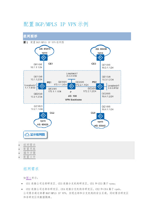
一、配置思路1、公网隧道配置本结点LSR ID1mpls lsr‐id *.*.*.*使能mpls 与 mpls ldp1系统模式下:2 mpls3 mpls ldp4接口模式下:5 interface ethernet 0/0/16 mpls7 mpls ldp【注】以上仅针对P、PE设备。
2、本地VPN创建VPN实例;配置RD、RT;绑定接口与VPN实例;将PE和CE之间的路由实例 与 VPN绑定;3、MP-BGP配置PE间的普通BGP邻居和MP-BGP邻居;将本地VPN路由和mp-bgp之间的路由相互引入二、配置示例组网需求:完成各VPN内部用户互通;地址规划:如下表设备名称P1PE2PE3CE4CE5……loopback / router id/ lsr-id 1.1.1.1 / 32 1.1.1.1 / 32 1.1.1.1 / 32 4.4.4.4 / 32 5.5.5.5 / 32……互联地址段从左到右设备数字组合数(如PE2与P1:10.0.21.0 / 24)……互联地址设备数字对应各自地址(如PE2:10.0.21.2 / 24)……其他详见下图……1、公网隧道配置P与PE的IGP路由(ospf);配置P与PE的LSR ID,并使能系统及接口下的mpls和mpls ldp功能;2、本地VPN创建VPN实例;配置RD、RT;1ip vpn‐instance company‐12 route‐distinguisher 100:13 vpn‐target 100:1 export‐extcommunity4 vpn‐target 100:1 import‐extcommunity56ip vpn‐instance company‐27 route‐distinguisher 100:28 vpn‐target 100:2 export‐extcommunity9 vpn‐target 100:2 import‐extcommunity10 //PE1与PE2该配置相同绑定私网接口与VPN实例;在PE上, 与对应用户(CE设备)相连接口与VPN进行绑定(CE设备无感知,接口只需普通地址配置);1 //以PE2为例,其他接口及PE相同2interface GigabitEthernet0/0/03 ip binding vpn‐instance company‐24 ip address 10.0.82.2 255.255.255.0将PE和CE之间的路由实例 与 VPN绑定;1 //PE22ospf 11 vpn‐instance company‐13 area 0.0.0.04 network 10.0.42.0 0.0.0.2555 //CE46ospf 117 area 0.0.0.08 network 10.0.42.0 0.0.0.2559 network 10.0.64.0 0.0.0.2553、MP-BGP配置PE间的普通BGP邻居(只能传递普通IPv4路由);1bgp 100 //PE2配置2 peer 3.3.3.3 as‐number 1003 peer 3.3.3.3 connect‐interface LoopBack045bgp 100 //PE3配置6 peer 2.2.2.2 as‐number 1007 peer 2.2.2.2 connect‐interface LoopBack0配置PE间的MP-BGP邻居(能传递BGP mpls VPN的私网路由,即VPNv4路由);建立MP-BGP邻居前提是PE间已经建立了普通的BGP邻居;1BGP 100 //PE2配置2 ipv4‐family vpnv43 peer 3.3.3.3 enable45BGP 100 //PE3配置6 ipv4‐family vpnv47 peer 2.2.2.2 enable配置本地VPN路由和mp-bgp之间的路由相互引入;建立MP-BGP邻居前提是PE间已经建立了普通的BGP邻居;1 bgp 100 //BGP中引入直连和IGP2 ipv4‐family vpn‐instance company‐13 import‐route direct4 import‐route ospf 115 ipv4‐family vpn‐instance company‐225 ip address 10.0.21.1 255.255.255.026 mpls27 mpls ldp28#29interface Ethernet0/0/130 ip address 10.0.13.1 255.255.255.031 mpls32 mpls ldp33#34interface Serial0/0/035 link‐protocol ppp36#37interface Serial0/0/138 link‐protocol ppp39#40interface Serial0/0/241 link‐protocol ppp42#43interface Serial0/0/344 link‐protocol ppp45#46interface GigabitEthernet0/0/047#48interface GigabitEthernet0/0/149#50interface GigabitEthernet0/0/251#52interface GigabitEthernet0/0/353#54wlan55#56interface NULL057#58interface LoopBack059 ip address 1.1.1.1 255.255.255.255 60#61ospf 162 area 0.0.0.027 accounting‐scheme default28 domain default29 domain default_admin30 local‐user admin password cipher F<Z4DJzy<+jKUGU‐KkpB7bo#31 local‐user admin service‐type http32#33firewall zone Local34 priority 1635#36interface Ethernet0/0/037 ip binding vpn‐instance company‐138 ip address 10.0.42.2 255.255.255.039#40interface Ethernet0/0/141 ip address 10.0.21.2 255.255.255.042 mpls43 mpls ldp44#45interface Serial0/0/046 link‐protocol ppp47#48interface Serial0/0/149 link‐protocol ppp50#51interface Serial0/0/252 link‐protocol ppp53#54interface Serial0/0/355 link‐protocol ppp56#57interface GigabitEthernet0/0/058 ip binding vpn‐instance company‐259 ip address 10.0.82.2 255.255.255.060#61interface GigabitEthernet0/0/162#63interface GigabitEthernet0/0/264#65interface GigabitEthernet0/0/366#67wlan68#69interface NULL070#71interface LoopBack072 ip address 2.2.2.2 255.255.255.25573#74bgp 10075 peer 3.3.3.3 as‐number 10076 peer 3.3.3.3 connect‐interface LoopBack077 #78 ipv4‐family unicast79 undo synchronization80 peer 3.3.3.3 enable81 #82 ipv4‐family vpnv483 policy vpn‐target84 peer 3.3.3.3 enable85 #86 ipv4‐family vpn‐instance company‐187 import‐route direct88 import‐route ospf 1189 #90 ipv4‐family vpn‐instance company‐291 import‐route direct92 import‐route ospf 1293#94ospf 195 area 0.0.0.096 network 10.0.21.0 0.0.0.25597 network 2.2.2.2 0.0.0.098#99ospf 11 vpn‐instance company‐1100 import‐route bgp101 area 0.0.0.0102 network 10.0.42.0 0.0.0.25525 authentication‐scheme default26 authorization‐scheme default27 accounting‐scheme default28 domain default29 domain default_admin30 local‐user admin password cipher F5S!+T‐YL&:z9:%F`[a=vbt#31 local‐user admin service‐type http32#33firewall zone Local34 priority 1635#36interface Ethernet0/0/037 ip address 10.0.13.3 255.255.255.038 mpls39 mpls ldp40#41interface Ethernet0/0/142 ip binding vpn‐instance company‐143 ip address 10.0.35.3 255.255.255.044#45interface Serial0/0/046 link‐protocol ppp47#48interface Serial0/0/149 link‐protocol ppp50#51interface Serial0/0/252 link‐protocol ppp53#54interface Serial0/0/355 link‐protocol ppp56#57interface GigabitEthernet0/0/058 ip binding vpn‐instance company‐259 ip address 10.0.39.3 255.255.255.060#61interface GigabitEthernet0/0/162#63interface GigabitEthernet0/0/264#65interface GigabitEthernet0/0/366#67wlan68#69interface NULL070#71interface LoopBack072 ip address 3.3.3.3 255.255.255.25573#74bgp 10075 peer 2.2.2.2 as‐number 10076 peer 2.2.2.2 connect‐interface LoopBack077 #78 ipv4‐family unicast79 undo synchronization80 peer 2.2.2.2 enable81 #82 ipv4‐family vpnv483 policy vpn‐target84 peer 2.2.2.2 enable85 #86 ipv4‐family vpn‐instance company‐187 import‐route direct88 import‐route ospf 1389 #90 ipv4‐family vpn‐instance company‐291 import‐route direct92 import‐route ospf 1493#94ospf 195 area 0.0.0.096 network 10.0.13.0 0.0.0.25597 network 3.3.3.3 0.0.0.098#99ospf 13 vpn‐instance company‐15 authentication‐scheme default6 authorization‐scheme default7 accounting‐scheme default8 domain default9 domain default_admin10 local‐user admin password cipher a9uRU{EO!7ECB7Ie7'/)Gbd#11 local‐user admin service‐type http12#13firewall zone Local14 priority 1615#16interface Ethernet0/0/017 ip address 10.0.35.5 255.255.255.018#19interface Ethernet0/0/120 ip address 10.0.57.5 255.255.255.021#22interface Serial0/0/023 link‐protocol ppp24#25interface Serial0/0/126 link‐protocol ppp27#28interface Serial0/0/229 link‐protocol ppp30#31interface Serial0/0/332 link‐protocol ppp33#34interface GigabitEthernet0/0/035#36interface GigabitEthernet0/0/137#38interface GigabitEthernet0/0/239#40interface GigabitEthernet0/0/32sysname Huawei3#4aaa5 authentication‐scheme default6 authorization‐scheme default7 accounting‐scheme default8 domain default9 domain default_admin10 local‐user admin password cipher {07;SSP`4Kpe}@HMNPn@fba#11 local‐user admin service‐type http12#13firewall zone Local14 priority 1615#16interface Ethernet0/0/017 ip address 10.0.39.9 255.255.255.018#19interface Ethernet0/0/120 ip address 10.0.90.9 255.255.255.021#22interface Serial0/0/023 link‐protocol ppp24#25interface Serial0/0/126 link‐protocol ppp27#28interface Serial0/0/229 link‐protocol ppp30#31interface Serial0/0/332 link‐protocol ppp33#34interface GigabitEthernet0/0/035#36interface GigabitEthernet0/0/137#38interface GigabitEthernet0/0/240interface GigabitEthernet0/0/341#42wlan43#44interface NULL045#46ospf 1447 area 0.0.0.048 network 10.0.39.0 0.0.0.25549 network 10.0.90.0 0.0.0.25550#51user‐interface con 052user‐interface vty 0 453user‐interface vty 16 2054#55return~ END ~。


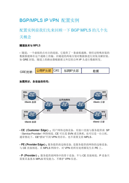
图1 配置BGP/MPLS IP VPN组网图组网需求如图1所示:•CE1连接公司总部研发区、CE3连接分支机构研发区,CE1和CE3属于vpna;•CE2连接公司总部非研发区、CE4连接分支机构非研发区,CE2和CE4属于vpnb。
公司要求通过部署BGP/MPLS IP VPN,实现总部和分支机构的安全互通,同时要求研发区和非研发区间数据隔离。
配置思路采用如下的思路配置BGP/MPLS IP VPN:1.P、PE之间配置OSPF,实现骨干网的IP连通性。
2.PE、P上配置MPLS基本能力和MPLS LDP,建立MPLS LSP公网隧道,传输VPN数据。
3.PE1和PE2上配置VPN实例,其中,vpna使用的VPN-target属性为111:1,vpnb使用的VPN-target属性为222:2,以实现相同VPN间互通,不同VPN间隔离。
同时,与CE相连的接口和相应的VPN实例绑定,以接入VPN用户。
4.PE1和PE2之间配置MP-IBGP,交换VPN路由信息。
5.CE与PE之间配置EBGP,交换VPN路由信息。
操作步骤1.在MPLS骨干网上配置OSPF协议,实现骨干网PE和P的互通# 配置PE1。
<Huawei> system-view[Huawei] sysname PE1[PE1] interface loopback 1[PE1-LoopBack1] ip address 1.1.1.9 32[PE1-LoopBack1] quit[PE1] interface gigabitethernet 3/0/0[PE1-GigabitEthernet3/0/0] ip address 172.1.1.1 24[PE1-GigabitEthernet3/0/0] quit[PE1] ospf 1[PE1-ospf-1] area 0[PE1-ospf-1-area-0.0.0.0] network 172.1.1.0 0.0.0.255[PE1-ospf-1-area-0.0.0.0] network 1.1.1.9 0.0.0.0[PE1-ospf-1-area-0.0.0.0] quit[PE1-ospf-1] quit# 配置P。


BGP/MPLS IP VPN 配置实例配置实例前我们先来回顾一下BGP MPLS的几个先关概念隧道技术与MPLS• 隧道:一个虚拟的点对点的连接。
它提供了一条虚拟通路,使经过特殊封装的数据报能够在这个通路上传输。
在隧道的两端分别对数据报进行封装及解封装。
如GRE封装,隧道上的路由器根据报文外层的公网IP头进行数据转发。
如图所示,各设备的作用:•CE(Customer Edge):用户网络边缘设备,有接口直接与服务提供商SP (Service Provider)网络相连。
CE可以是SVN或交换机,也可以是一台主机。
通常情况下,CE“感知”不到VPN的存在,也不需要支持MPLS。
•PE(Provider Edge):服务提供商边缘设备,是服务提供商网络的边缘设备,与CE直接相连。
在MPLS网络中,对VPN的所有处理都发生在PE上。
•P(Provider):服务提供商网络中的骨干设备,不与CE直接相连。
P设备只需要具备基本MPLS转发能力,不维护VPN信息。
用户设备所在的区域,称为一个站点(Site),站点是指相互之间具备IP连通性的一组IP系统,并且这组IP系统的IP连通性不需通过运营商网络实现。
传统的VPN技术存在一些固有的缺陷,导致客户组网时的很多需求无法得到满足,并且实施比较复杂,MPLS VPN的出现解决了传统VPN技术的固有缺陷——地址空间的重叠问题。
• MPLS是天然的隧道,隧道上的路由器可以根据报文的MPLS头进行报文转发。
VRF(Virtual Routing and Forwarding):虚拟路由及转发,它是一种VPN 路由和转发实例。
• 一台PE 路由器,由于可能同时连接了多个VPN 用户,这些用户(的路由)彼此之间需要相互隔离,那么这时候就用到了VRF,PE 路由器上每一个VPN 都有一个VRF。
PE 路由器除了维护全局IP 路由表之外,还为每个VRF 维护一张独立的IP 路由表,这张路由表称为VRF 路由表。