Y-1031说明书(中文版)
- 格式:docx
- 大小:169.19 KB
- 文档页数:3
ITV1000-※1ITV2000-※1ITV3000-※1(模拟输出/电压型)使用说明书值此,谨对您选购SMC公司的产品表示诚挚的谢意。
请仔细阅读本使用说明书,相信必将有助于您正确使用本产品。
为以防万一,请您一定好好保管此说明书。
安全注意事项这里所描述到的,是提请您正确安全的使用本产品,以防止对您自身和他人造成危害和损害的各种注意事项。
请结合ISO 4414, JIS B 8370以及其他的相关安全规则,务必遵守。
!注意关于配管1.请将配管用空气吹净或清洗干净,以除去配管内的切屑,切削油及杂质等。
2.将配管和管接头拧紧时,请注意勿将配管的螺纹切屑及密封材混入配管中。
另需强调,使用密封胶带包卷管接头螺纹时,请在螺纹先端留出1.5~2个螺距的空间。
!注意关于压缩气源1. 在靠近本产品的供气侧,请选择安装过滤精度在5μm以下的空气过滤器。
2. 压缩空气若含有大量的水分,将导致本产品及其他的气动元件作动不良。
请实施相应对策,诸如设置后冷却器,空气干燥器,水分分离器等。
3. 由空气压缩机所产生的碳粉在本产品内部大量附着时,将导致其作动不良。
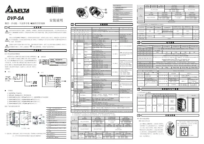
各部分名称外形尺寸安装孔配线电缆接线端子UP键(△键)设定键(SET键)DOWN键(▽键)安装托架(选配)右弯出线型电缆接线端子显示用LED(4芯)SUP接口压力表用接口OUT接口外形尺寸安装孔安装孔安装托架安装托架(选配)(选配)直线出线型电缆接线端子(4芯)右弯出线型电缆接线端子(4芯)安装孔■ 规格供给压力 注1) 设定压力+ 0.1MPa,但最大为1MPa0.005~0.1MPa (ITV101※-※1,ITV201※-※1,ITV301※-※1)0.005~0.5MPa (ITV103※-※1,ITV203※-※1,ITV303※-※1)设定压力0.005~0.9MPa (ITV105※-※1,ITV205※-※1,ITV305※-※1)约200L/min (ANR) {ITV1000}(供给压力:0.7MPa)约1500L/min (ANR) {ITV2000}(供给压力:0.7MPa)最大流量约5000L/min (ANR) {ITV3000}(供给压力:0.7MPa)24VDC±10% (ITV10※0-※1,ITV20※0-※1,ITV30※0-※1)电源电压 注2)12~15VDC (ITV10※1-※1,ITV20※1-※1,ITV30※1-※1)电源电压 DC24V型:0.12A以下消费电流电源电压 DC12~15V型:0.18A以下4~20mADC (ITV10※※-01,ITV20※※-01,ITV30※※-01)电流型0~20mADC (ITV10※※-11,ITV20※※-11,ITV30※※-11)0~5VDC (ITV10※※-21,ITV20※※-21,ITV30※※-21)输入信号 注2)电压型0~10VDC (ITV10※※-31,ITV20※※-31,ITV30※※-31)电流型 250Ω以下输入阻抗电压型 约6.5KΩ直线性 ±1.0% F.S.以下延滞性 0.5% F.S.以下重复精度 ±0.5% F.S.以下最小压力调整 :调整范围 额定值的0~50%最大压力调整 :调整范围 额定值的10~100%附加机能键锁定机能 :持续摁住UP键2秒以上,再摁住SET键,可实现对操作键的锁定。
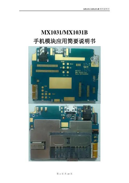
MX1031/MX1031B 手机模块应用简要说明书一、 概述:二、 原理框图:三、 功能接口简介:3.1音频接口3.2LCD接口3.3I/O接口3.3.1充电功能3.3.2耳机功能3.3.3FM收音机天线3.3.4RS232接口3.3.5USB数据传输3.4马达接口3.5电池接口3.6天线馈点及RF测试点3.7蓝牙3.8摄像头接口3.9手电接口3.10DC充电接口3.11按键FPC接口3.12FM内置天线四、 模块版本信息五、 结构尺寸:一、 概述:本说明书简要介绍MX1031/MX1031B手机模块各接口定义及快速手机开发。
本说明书仅用于MX1031/MX1031B版。
三、 功能接口简介:3.1 音频接口:MX1031/MX1031B模块上共有一个焊线式受话器接口;一个弹片式受话器,示意图如下:3.2 LCD接口MX1031/MX1031B V00主板提供一个液晶屏MIPI接口,该接口支持串联LCD背光。
LCD接口定义:管脚号 管脚定义 说明1 LCD ID2 需兼容不同屏时ID1、ID2要不同电平组合2 VDD283 VDD_IO 2.8V/1.8V,主板接1.8V4 LCD ID1 需兼容不同屏时ID1、ID2要不同电平组合5 RSET 复位6 GND7 LPTE 同步信号8 NC9 GND10 LED_N 串联背光负板11 LED_P 串联背光正板12 LED_N 串联背光负板13 LED_P 串联背光正板14 GND15 LMIPI_D0N16 LMIPI_D0N17 GND18 LMIPI_CN19 LMIPI_CP20 GND21 LMIPI_D1N 如果液晶屏只需一路MIPI,此管脚悬空22 LMIPI_D1P 如果液晶屏只需一路MIPI,此管脚悬空23 GND3.3主板与按键小板FPC连接接口MX1031/MX1031 V00主板支持小板FPC扩展,支持的功能:双喇叭,马达,MIC,23个按键,3路按键背光灯(可做指示灯)。
毕业设计(论文)说明书题目:减压控制阀的设计系名机械工程系专业机械设计制造及其自动化学号6012201230学生姓名周翔指导教师朱家玲2016年5月20日摘要随着工业技术的发展,液压系统在当今机械领域用途越来越广泛,各种大、中、小型液压设备中,液压减压阀是系统中的一个关键性的压力控制元件,它们的性能和寿命在很大程度上决定着整个液压系统的平稳性和工作能力。
设计中对减压阀结构进行了探讨,并且比较了两种方案的优劣特点,选择了管式螺纹连接定值输出减压阀。
在现有的减压阀基础上通过改变主阀芯的材料,从而提高减压阀的灵敏度,使产品在满足设计条件要求的情况下,更加经济合理化。
在这次毕业设计中主要参考了DR50型先导式减压阀的相关产品的结构和技术参数,并以其为基础,重新设计了先导式定值输出液压减压阀阀芯的结构参数,通过计算和不断优化使减压阀的部分或整体性能有所提高完善。
关键词:先导式减压阀;管式连接;阀芯结构参数AbstractAlong with the development of the technology industry, Hydraulic system in tod- ay's machinery field use more and more widely, In all the big or small hydraulic equi- pment, Hydraulic pressure reducing valve is system of a key pressure control compo- nents.This design mainly in the market today of the pressure reducing valve for the fo- undation, Pilot type setting value output pressure reducing valve design. In the gradu- ation design process adopted some of the pressure reducing valve about new technolo- gy and new ideas, And used topilot type setting value output pressure reducing valve design, In the design of pressure reducing valve structure were discussed.In the graduation design main reference the forerunner of the pressure reducing valve DR50 type of related products structure and technical parameters, And as the f- oundation, To guide the design of hydraulic pressure reducing valve setting value ou- tput valve core structure parameters, Through calculation and continuous optimization of the pressure reducing valve to part or whole performance improved perfect.Key words:Pilot Operated Reducing Valves;Tube Type Conjunction;The Valve Core Structure Parameters目录第一章引言 (1)第二章减压阀 (3)2.1 减压阀的简介 (3)2.2 定值减压阀 (3)2.3 定比减压阀 (5)2.4 定差减压阀 (6)2.5 我国引进的德国力士乐公司压力阀系列 (7)第三章设计方案的分析与选定 (9)3.1 设计的目的及范围 (9)3.2 设计的任务要求 (9)3.3 设计的总体思路 (9)3.4 设计方案的对比与确定 (10)第四章减压阀的结构设计及计算 (12)4.1 减压阀的设计内容 (12)4.2 减压阀的设计步骤 (12)4.2.1 主要结构尺寸的初步确定 (12)4.2.2 主阀弹簧的设计 (14)4.2.3 先导阀弹簧的设计计算 (17)第五章减压阀结构材料的选择及回油路的设计205.1 减压阀主要构件的材料选择 (20)5.1.1 阀体(壳体)的材料选择 (20)5.1.2 阀芯与阀套的材料选择 (20)5.1.3 先导式减压阀的远程控制口K的用途 (20)5.1.4 液压阀主要构件加工工艺 (20)5.2 减压阀回油路的设计 (21)5.2.1 减压回路的工作原理 (21)5.2.2 减压阀设计应该注意事项 (22)5.2.3 减压阀常见的故障及诊断排除 (22)第六章减压阀的性能指标及造型 (25)6.1 减压阀的主要静态性能指标 (25)6.2 减压阀的动态性能 (26)6.3 减压阀的设计造型图 (27)第七章结论 (29)参考文献 (30)外文资料中文译文致谢第一章引言液压技术在功率密度、结构组成、响应速度、调速保护、过载保护、电液整台等方面都具有一定的优势,使其成为现代传动的重要技术手段和不可替代的关键基础技术之一,这些应用已经遍及了国民经济各个领域。

1-888-PHILIPS(744-5477)or visit us on the web at 按下SETUP(设定)这时会出现一个功能列表。
以下功能在播放时可用:暂停按下2;键可暂停播放。
您可以再次按下键以恢复播放。
上一节目/下一节目轻按J((或)曲目快退/快进按住J(或)K开始快退后,快速按下J(8x、16x、32x 或恢复正常播放。
您也可以按2;恢复正常播放。
音量控制轻按+或-键或反复按它们可增加或减少音量重复按下OPTIONS曲目或重复所有曲目随机播放按下OPTIONS机播放停止轻按播放器右侧的以下功能在播放时可用:暂停按下2;键可暂停播放。
您可以再次按下2;键以继续播放。
上一节目/下一节目轻按J(或)K旋转按下OPTIONS式。
然后使用2键逆时针旋转图像。
按下项)键可退出旋转模式。
缩放放大屏幕,然后使用导航键拍摄屏幕。
按下ZOOM(缩放)使用本功能停止轻按播放器右侧的5播放结束时,将 USB 闪存盘或您可以获得相应的功能和信息:亮度使您能够调整屏幕的亮度对比使您能够调整屏幕的对比度色彩使您能够根据冷、暖和标准色彩调整屏幕的颜色。
关闭 LCD在与电视相连或播放音乐光盘等情况下,您可以关闭屏幕。
这样可以节省电池的电量您的产品是由可以再生利用的优质材料和组件设计、制造而成的。
如果某一件产品上贴有交叉轮状回收箱标志,则表示该产品受第请了解当地有关电气和电子产品收集的专属制度。
请遵守当地的规定,不要将废旧产品与一般家庭废品一起处理。
正确处理您的废旧产品,利于防止对环境和人类健康产生潜在负面影响。
中国印刷 wk804规格更改恕不另行通知。
商标为荷兰皇家飞利浦电子股份有限公司或其各自所有者的专有财产。
2008荷兰皇家飞利浦电子股份有限公司。
版权所有。
Meet Philips at the Internet。
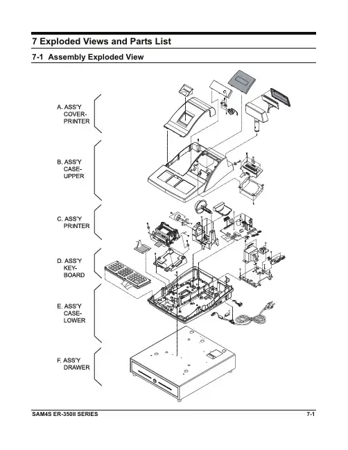
7 Exploded Views and Parts List 7-1 Assembly Exploded ViewG7. Exploded Views and Parts List7-2 Ass’y Cover-PrinterGGFigure7-1 Ass’y Cover-PrinterNo Parts-No. Description/Specification Q'ty Design-Location Serviceable Remark A-1 JK97-01060B MEA-WINDOW JOURNAL 1͑Y ͑A-1-1 JK72-40204A PMO-WINDOW JOURNAL 1͑NA-1-2 JK70-00056A IPR-CUTTER PAPER 1͑N ͑A-2 JK72-20094A PMO-COVER PRINTER 1͑Y ͑GGGGGGGGGGGGGGGGGG7. Exploded Views and Parts Lists7-3 Ass’y Case-UpperGFigure7-2 Ass’y Case-Upper7. Exploded Views and Parts ListNo Parts-No. Description/Specification Q'ty Design-Location Serviceable Remark B-1 JK72-20061H PMO-COVER MODE S/W 1͑Y ͑B-2 6002-000319 SCREW-TAPPING 2B/MODE + SWITCH ROTARY Y ͑B-3 JK70-10004A IPR-BRKT MODE_S/W 1͑Y ͑B-4 6002-000319 SCREW-TAPPING 2B/MODE + C/MODE S/W Y ͑B-5 6002-000172 SCREW-TAPPING 1C/UPPER + C/LOWER Y ͑B-6 JK96-10044A MODE KEY ASSY 1͑Y ͑B-7 JK72-40901A PMO-WINDOW DISPLAY 1͑Y ͑B-8 JK72-40209B PMO-WINDOW TURRET 1͑Y ͑B-9 JK92-01231A PBA TURRET 1͑Y ͑B-10 JK72-00015A PMO-TURRET BODY 1͑Y ͑B-11 6001-000367 SCREW-MACHINE 1͑Y ͑B-12 JK70-40305A ICT-SHAFT MOLDING;ER-350IIF,STD 1ER-350IIF,STD Y ͑JK72-00012A PMO-CASE UPPER;ER-350II,STD 1͑Y ͑B-13JK72-00012B PMO-CASE UPPER;ER-350IIF,FISCAL 1͑Y ͑B-14 6002-000175 SCREW-TAPPING 4PBA-SUB + B/WINDOW PCB YB-15 JK92-01242A PBA SUB-380,DISPLAY 1YB-16 JK70-10407A IPR-BRKT WINDOW PCB 1͑Y ͑B-17 6002-000175 SCREW-TAPPING 4B/WINDOW PCB + C/UPPER Y ͑GGGGGGGGGGGGGGGGGGGGGGGGGGG7. Exploded Views and Parts Lists7-4 Ass’y PrinterGFigure7-3 Ass’y PrinterNo Parts-No. Description/Specification Q'ty Design-Location Serviceable Remark C-1 JK59-20002A UNIT-PRINTER ASS'Y 1YC-2 6002-000209 SCREW-TAPPING 4PRT ASS'Y+HODLER PRINTER YC-3 JK73-40201A RMO-PRINTER 4PRT ASS'Y+HODLER PRINTER YC-4 JK60-00001A SCREW-ASSY TAPTITE 1PRT(L)+D/R CENTER YC-5 JK39-40011A CBF HARNESS 1YC-6 JK39-40564A CBF SIGNAL-PRINTER FFC 1YC-7 JK60-00001A SCREW-ASSY TAPTITE 1PRT(R)+B/TRANS YC-8 JK39-40021A CBF HARNESS 1YC-9 6002-000175 SCREW-TAPPING 2H/PRINTER+CASE-LOWER YC-10 JK72-20095A PMO-HOLDER PRINTER 1YGGG7. Exploded Views and Parts List* SDM-310A Exploded ViewGGGGGGGGGGGGGGGGGGGGGGGGGGGGGGGGGGGGGGGGGGGGGGFigure7-4 SDM-310A Printer-AssemblyG7. Exploded Views and Parts ListsFigure 7-5 Lubrication Points of the Printer (SDM-310A)7. Exploded Views and Parts List* SDM-310A Parts ListNo. Code No. Description / Specification Q`ty Design-Location Serviceable Remark1 JK70-20053A IPR-COVER HEAD 1Y2 JK70-50049A SCREW-MACHINE 2F/Ribbon + F/Main Y3 JK70-20056A IPR-FRAME RIBBON 1Y4 JK72-20200A PMO-LATCH RIBBON 1Y5 JK72-20202A PMO-WORM WHEEL 1Y6 JK70-70026A ICT-LEADSCREW 1Y7 JK72-20184A PMO-BUSHING CAM 1LeadScrew R Y8 JK72-20194A PMO-GEAR SCREW 1LeadScrew R Y9 JK72-20193A PMO-GEAR IDLE 33 1S/Plate Y10 JK72-20191A PMO-SWING PLATE 1LeadScrew R Y11 JK70-50022A POLY WASHER 1LeadScrew R Y12 JK70-50047A SCREW-TAPTITE 2C/Paper + P/Plate Y13 JK70-20054A IPR-CUTTER PAPER 1Y14 JK75-20028A ASSY-PLATEN PLATE 1P/Plate + D/Plate Y15 JK72-20203A PMO-PLATEN PLATE 1N16 JK70-60018A RMO-TAPE PLATE 1N17 JK70-20057A IPR-DAMPER PLATE 1N18 JK70-70028A ICT-SHAFT PLATEN 1Y19 JK75-20029A ASSY-ROLLER FEED 1Roller+Bushing+Gear Y20 JK72-20196A PMO-GEAR ROLLER 1N21 JK70-50019A ICT-BUSHING_PI4 1N22 JK59-40008A UNIT-ROLLER FEED 1S/Roller + Rubber N23 JK70-50049A SCREW-MACHINE 2C/Upper + F/Main Y24 JK72-20186A PMO-PARTITION PAPER 1C/Upper Y25 JK72-20185A PMO-COVER UPPER 1Y26 JK72-20201A PMO-ROLLER GUIDE 1Y27 JK72-20197A PMO-ROLLER PRESSURE 2S/Pressure Y28 JK70-70029A ICT-SHAFT PRESSURE 1Y29 JK70-30012A SPRING-PRESSURE 2Guide Bottom Y30 JK72-20187A PMO-GUIDE BOTTOM 1Y31 JK59-40006A UNIT-DOT PRINT HEAD 1Y32 JK75-20032A ASSY-HEAD CARRIAGE 1Head + Bushing + I/Pin Y33 JK92-01391A PBA SUB-P_END 1Y34 6003-000110 SCREW-TAPTITE 1G/Bottom+PBA P_END Y35 JK59-40007A UNIT-MOTOR STEP FEED 1Y7. Exploded Views and Parts Lists* SDM-310A Parts ListNo. Code No. Description / Specification Q`ty Design-Location Serviceable Remark36 JK59-40007B UNIT-MOTOR STEP CR 1Y37 JK70-50053A SCREW-MACHINE 2PPG+F/Main Y38 JK70-20058A IPR-PPG 1Y39 6044-000159 E-RING 1F/Main +G/Knob Y40 JK72-20199A PMO-GEAR KNOB 1Y41 JK72-20192A PMO-GEAR IDLE 27 1Y42 6044-000159 E-RING 1F/Main +G/Reduction Y43 JK72-20195A PMO-GEAR REDUCTION 1Y44 JK70-70027A ICT-SHAFT HEAD 1Y45 JK70-50048A SCREW-TAPTITE 4G/Bottom+F/Main Y46 JK70-50004A POLY WASHER 1S/Platen + Trigger L Y47 JK72-20189A PMO-TRIGGER L 1Y48 JK70-50048A SCREW-MACHINE 2F/Main + Motor/Feed Y49 6044-000159 E-RING 1LeadScrew L Y50 6044-000231 E-RING 1F/main + S/Head Y51 JK70-50049A SCREW-MACHINE 2Y52 JK39-50001A CABLE-FPC 1Y53 JK92-01390A PBA SUB-MECHA PCB 1Y54 JK97-20053A ASSY-FRAME MAIN 1F/Main + B/Cam Y55 JK72-20190A PMO-TRIGGER R 1Y56 JK70-50004A POLY WASHER 1S/Platen + Trigger R Y57 JK70-50019A ICT-BUSHING_PI4 1Y58 6044-000159 E-RING 1Roller Feed Y59 JK70-50051A WASHER PLAIN 2Ass’y Worm Y60 JK70-50048A SCREW-MACHINE 2F/Main + Motor/CR Y61 JK75-20030A ASSY-WORM GEAR 1W/Gear + Shaft Y62 JK70-50050A POLY WASHER 1W/Wheel + F/Main Y63 6044-000121 E-RING 1Ass’y Worm + F/main Y64 JK70-50052A SCREW-DELTA PT 2Head + H/Carriage Y65 JK70-50002A ICT-BUSHING 1Ass’y Worm YGGGGGGGGGGGGG7. Exploded Views and Parts List7-5 Ass’y Key-BoardGGGFigure7-6 Ass’y Key-BoardNo Parts-No. Description/Specification Q'ty Design-Location Serviceable RemarkD JK59-10512A UNIT-KEYBOARD;44KEY,ENGLISH 1 ͑Y ͑D-1 JK81-10945A KEY-CAP(S);1X1 26͑Y ͑D-2 - LABEL-KEY TOP SET 1 ͑N ͑D-3 JK81-20013A KEY-TOP ASS'Y(S);1X1 26͑Y ͑D-4 JK81-10285T SPRING RETURN;1X1 41͑Y ͑D-5 JK81-10946A KEY-CAP(L);1X2 3 ͑Y ͑D-6 JK81-20014A KEY-TOP ASS'Y(L);1X2 3 ͑Y ͑D-7 JK81-20001A SPRING-RETURN;1X2 6 ͑Y ͑JK81-10933A KEY-TOP,1 1 ͑Y ͑JK81-10934A KEY-TOP,2 1 ͑Y ͑JK81-10935A KEY-TOP,3 1 ͑Y ͑JK81-10936A KEY-TOP,4 1 ͑Y ͑JK81-10937A KEY-TOP,5 1 ͑Y ͑JK81-10938A KEY-TOP,6 1 ͑Y ͑D-8JK81-10939A KEY-TOP,7 1 ͑Y ͑JK81-10940A KEY-TOP,8 1 ͑Y ͑JK81-10941A KEY-TOP,9 1 ͑Y ͑JK81-10942A KEY-TOP,0 1 ͑Y ͑JK81-10943A KEY-TOP,00 1 ͑Y ͑JK81-10944A KEY-TOP,Ɣ 1 ͑Y ͑D-9 JK72-60448A HOUSING 1 ͑Y ͑D-10 JK81-10949A FPC ASS'Y 1 ͑Y ͑D-11 JK70-10422A FRAME(T0.8) 1 ͑Y ͑D-12 6002-000114 SCREW TAPPING 2 ͑Y ͑GGGGGGGGGGGGGGGGGGGG7-6 Ass’y Case-LowerGFigure7-7 Ass’y Case-LowerNo Parts-No. Description/Specification Q'ty Design-Location Serviceable RemarkE-1 6002-000175 SCREW-TAPPING 2P/SUPPLY+B/SPOOL Y ͑E-2 JK96-10036A ELA ETC-MOTOR SPOOL 1Y ͑E-3 JK73-30200A RCT-MOTOR 1YE-4 JK70-20024A IPR-BRKT SPOOL MOTOR 1YE-5 JK70-50014A SCREW-MACHINE 2YE-6 JK72-20057A PMO-PULLEY WINDING(2") 1YE-7 6002-000174 SCREW-TAPPING 3P/SUPPLY+C/LOWER YE-8 JK72-20103A PMO-DUMMY SUPPLY 1YE-9 JK72-20096A PMO-PAPER SUPPLY 1YE-10 6002-000175 SCREW-TAPPING 2P/SUPPLY+D/SUPPLY YE-11 6006-000199 SCREW-ASS'Y TAPT 2B/TRANS+TRANS Y JK26-00014A TRANS POWER-EUROPE:230V,50Hz 1YE-12JK26-00015A TRANS POWER-EUROPE:120V,60Hz 1YE-13 6002-000175 SCREW-TAPPING 2C/LOWER + POWER S/W B’D YE-14 JK92-01227B PBA SUB-POWER SW 1YE-15 6001-000666 SCREW-MACHINE 1Y JK92-10281A PBA SUB-I/F:232,1PORT 1YE-16JK92-10280A PBA SUB-I/F: RS232,2PORT 1YJK92-10279A PBA SUB-I/F:RS232(1PORTS),RJ45(2PORTS) 1YE-17 6002-000174 SCREW-TAPPING 2B/TRANS+C/LOWER YE-18 JK60-00001A SCREW-ASSY TAPTITE 1B/TRANS+PRT GND YE-19 6006-000187 SCREW-ASS'Y MACHINE 1B/TRANS+P/CORD GND YE-20 JK60-00001A SCREW-ASSY TAPTITE 1B/TRANS+D/R GND YE-21 JK70-20018B IPR-BRKT TRANS 1YE-22 6002-000171 SCREW-TAPPING 1C/LOWER+BRKT CASING YE-23 JK70-10002A IPR-BRKT CASING 1͑Y JK72-20182A PMO-CASE LOWER: 1YJK72-20182B PMO-CASE LOWER:SERIAL 1 1YJK72-20182C PMO-CASE LOWER:SERIAL 2 1YE-24JK72-20182D PMO-CASE LOWER:SERIAL 3 1YJK72-20182E PMO-CASE LOWER:ONLY POWER S/W 1YJK72-20182F PMO-CASE LOWER:NON HOLE 1YE-25 JK39-00008B CBF-HARNESS-POWER S/W 1Y JK39-10002A CBF-POWER CORD;AUSTRALIA 1͑Y ͑JK39-10003A CBF-POWER CORD;USA 1͑Y ͑E-26JK39-10008A CBF-POWER CORD;UK 1͑Y ͑JK39-10501A CBF-POWER CORD;EUROPE 1͑Y ͑E-27 6003-001149 SCREW-TAPTITE 1C/LOWER+D/R CENTER GND Y ͑E-28 JK72-40205A PMO-CASE FISCAL 1YJK92-01284C PCB-SUB FISCAL:1M BIT 1YE-29JK92-01284D PCB-SUB FISCAL:2M BIT 1YE-30 6002-000175 SCREW-TAPPING 3B/TRANS+C/LOWER YE-31 JK39-40602A HARNESS-I/F 1Y JK92-01393A PBA MAIN-BOARD:ER-350IIF,FISCAL,232 1Y VENEZUELA JK92-01393B PBA MAIN-BOARD:ER-350IIF,FISCAL,232 1Y GREECEJK92-01394A PBA MAIN-BOARD:ER-350IIF,FISCAL,STD 1Y MEXICO E-32JK92-01395A PBA MAIN-BOARD:ER-350II,232 1Y MUL JK92-01396A PBA MAIN-BOARD:ER-350II,STD 1Y STD JK92-01397A PBA MAIN-BOARD:ER-350II,CRS 1Y USAG7-7 Ass’y Drawer(a) Ass’y Bill-Coin (4B/8C, 5B/5C)No. Code No. Description / Specification Q`ty Design-Location Serviceable Remark JK97-20014A MEA-UNIT BILL COIN: 4B8C 1 ͑Y ͑aJK97-00407A MEA-UNIT BILL COIN: 5B5C 1 ͑Y ͑a-1 JK72-40267A PMO-LEVER PRESS 4 ͑Y ͑a-2 6107-000134 SPRING ES 4 ͑Y ͑a-3 JK70-10314A IPR-HOLDER LEVER 4 ͑Y ͑a-4 6002-000175 SCREW-TAPPING 3 ͑Y ͑a-5 6002-001078 SCREW-TAPPING 4 ͑Y ͑a-6 JK70-10304A IPR-PLATE HOLDER 1 ͑Y ͑a-7 JK72-40269A PMO-PANEL PARTITION 3 ͑Y ͑JK72-20088A PMO-BILL COIN TILL: 4B8C 1 ͑Y ͑a-8JK72-40268A PMO-BILL COIN TILL: 5B5C 1 ͑Y ͑a-9 JK72-20090A PMO-COIN PARTITION: 4B8C 6 ͑Y ͑a-10 JK72-20089A PMO-COIN TILL: 4B8C 1 ͑Y ͑(a) Ass’y Bill-Coin (7B/8C)No. Code No. Description / Specification Q`ty Design-Location Serviceable Remarka JK97-01103A MEA-UNIT BILL COIN: 7B8C 1 Ya-1 6002-000175 SCREW-TAPPING 3 Ya-2 JK70-00068A IPR-HOLDER PLATE 1 Ya-3 JK72-00083A PMO-BILL PARTITION 5 Ya-4 JK72-00082A PMO-BILL TILL 2 Ya-5 JK72-00084A PMO-BILL COIN TILL 1 Y(b) Ass’y Tray-TillNo. Code No. Description / Specification Q`ty Design-Location Serviceable Remark JK97-01073B MEA-UNIT TRAY TILL: 5B5C 1 Y bJK97-01073D MEA-UNIT TRAY TILL: 4B8C,7B8C(EURO) 1 Y b-1 JK75-10389A MEC-LOCK: DRAWER 1 YJK70-10014A IPR-PLATE FRONT 1 Y b-2JK70-10014B IPR-PLATE FRONT 1 YJK75-00025A MEA-TRAY TILL: 4B8C,7B8C 1 N b-3JK75-00025B MEA-TRAY TILL: 5B5C 1 N b-4 JK73-10203A RPR-TENSION 2 Nb-5 JK75-10386A MEC-ROLLER 2 Yb-6 6031-000549 WASHER-PLAIN 2 Yb-7 6003-000221 SCREW-TAPTITE 1 Yb-8 JK70-10324A IPR-SUPPORT TRAY 1 Nb-9 JK70-40302A ICT,SHAFT PIN 1 Nb-10 6044-000124 RING-E 1 Yb-11 6002-001042 SCREW-TAPPING 2 Yb-12 JK70-10323A IPR-PLATE CLIP 1 YG(c) Ass’y HiousingNo. Code No. Description / Specification Q`ty Design-Location Serviceable Remark JK97-01074A MEA-COVER HOUSING 1 Y cJK97-01074B MEA-COVER HOUSING: NONE HOLE(OPTION) 1 YJK75-00026A MEA-SUB HOUSING 1 ͑Y ͑c-1JK75-00026B MEA-SUB HOUSING: NONE HOLE(OPTION) 1 ͑Y ͑c-2 JK75-10386A MEC-ROLLER: DRAWER 2 ͑Y ͑c-3 JK73-20207A REX-PAD DRAWER 2 ͑N ͑(d) Ass’y LockNo. Code No. Description / Specification Q`ty Design-Location Serviceable RemarkJK97-00985A MEA-UNIT LOCK: 2-LATCH,LONG LEVER 1 ͑Y ͑dJK97-00987A MEA-UNIT LOCK: 2-LATCH,SHORT LEVER 1 ͑Y ͑d-1 6002-000157 SCREW-TAPPING 1 ͑Y ͑d-2 JK73-20210A REX-BUMPER 1 ͑Y ͑d-3 JK61-70100A SPRING-PUSH 1 ͑Y ͑JK75-00027A MEC-LOCK LEVER: 2-LATCH,LONG LEVER 1 ͑Y ͑d-4JK75-00027B MEC-LOCK LEVER: 2-LATCH,SHORT LEVER 1 ͑Y ͑d-5 6107-001014 SPRING-ES 1 ͑Y ͑d-6 JK33-10500A SOLENOID-DC 1 ͑Y ͑d-7 6001-000131 SCREW-MACHINE 2 ͑Y ͑d-8 6001-000525 SCREW-MACHINE 2 ͑Y ͑d-9 3405-001013 SWITCH-MICRO 1 ͑Y ͑d-10 JK39-40301R CBF-HARNESS 1 ͑Y ͑d-11 6002-000161 SCREW-TAPPING 3 ͑Y ͑(e) Ass’y BottomNo. Code No. Description / Specification Q`ty Design-Location Serviceable RemarkJK97-01976A MEA-UNIT BOTTOM 1 Y eJK97-01076B MEA-UNIT BOTTOM: UNIVERSAL 1 Y e-1 JK70-10938A IPR-PLATE BOTTOM 1 YJK73-40200A RMO-STOPPER 2 Y e-2JK73-10902A RMO-STOPPER: UNIVERSAL 2 Y e-3 JK61-40200A RMO-FOOT RUBBER 4 Ye-4 6002-000234 SCREW-TAPPING 4 Ye-5 6003-000267 SCREW-TAPTITE 6 Ye-6 6003-000267 SCREW-TAPTITE 2 Ye-7 JK70-10401A IPR-PLATE SPRING 2 Ye-8 6003-000267 SCREW-TAPTITE 4 Y。
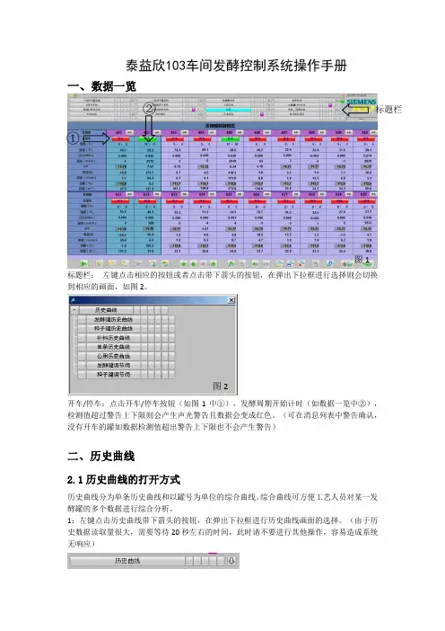
泰益欣103车间发酵控制系统操作手册一、数据一览标题栏: 左键点击相应的按钮或者点击带下箭头的按钮,在弹出下拉框进行选择则会切换到相应的画面,如图2。
开车/停车:点击开车/停车按钮(如图1中①),发酵周期开始计时(如数据一览中②),检测值超过警告上下限则会产生声光警告且数据会变成红色。
(可在消息列表中警告确认,没有开车的罐如数据检测值超出警告上下限也不会产生警告)二、历史曲线2.1历史曲线的打开方式历史曲线分为单条历史曲线和以罐号为单位的综合曲线。
综合曲线可方便工艺人员对某一发酵罐的多个数据进行综合分析。
1:左键点击历史曲线带下箭头的按钮,在弹出下拉框进行历史曲线画面的选择。
(由于历史数据读取量很大,需要等待20秒左右的时间,此时请不要进行其他操作,容易造成系统无响应)标题栏图1①②图22:点击流程图画面上模拟量检测点,在弹出的操作画面中点击右上角菜单栏中的①,即打开选择的模拟量历史曲线。
模拟量监测点①⑳ ⑮ ⑰ ⑭ ⑩ ⑫2.2综合历史曲线注:X 轴为时间轴,Y 轴为对应当前曲线量程轴 工具栏图标含义:①:第一个数据记录:使用此按钮在趋势窗口中显示变量在特定时间段内的趋势。
(通过按“停止”图标中断更新时才能启用该按钮)②:上一个数据记录:此按钮用于在趋势窗口中显示变量在当前显示的时间间隔之前的一段时间内的趋势。
(通过按“停止”图标中断更新时才能启用该按钮)③:下一个数据记录:此按钮用于在趋势窗口中显示变量在当前显示的时间间隔之后的一段时间内的趋势。
(通过按“停止”图标中断更新时才能启用该按钮)④:最后一个数据记录:此按钮用于在趋势窗口中显示变量在以最后一个归档值结束的指定时间段内的趋势。
(通过按“停止”图标中断更新时才能启用该按钮)⑤:缩放区域:可以通过在趋势窗口中拖动鼠标选择一块区域,趋势窗口的所选区域会被⑪ 工具栏曲线选择标尺统计范围统计范围数据显示区⑱⑯ ⑲ ⑬ ⑨ ⑧ ③ ① ⑦ ⑥ ⑤ ② ④放大。
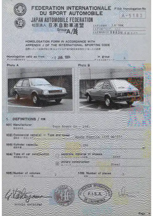
<T p 7^' ^*fIFEDERATION INTERNATIONALEF IS A Homologation NoDU SPORT AUTOMOBILEJAPAN AUTOMOBILE FEOERATIONJ A - 064A -5183Group 7iv—-rA /MJ A F £^l £.r ^u -r ^/|HOMOLOGATION FORM IN ACCORDANCE WITHAPPENDIX J OF TH E INTERNATIO NAL SPORTING CODE.-K —y S*f+giJ J iMCij i: t/J A FHomologation valid as from _ « u u igg^FISA lêîr^H B _________________~ ‘in group.F I S A2;lgr;u-rPhoto APhoto BI1. D E F IN IT IO N S / S #I C I) ManufacturerToyo Kogyo Co., Ltd.102) Commercial name(s) — Type and modelMazda Familia 1300 BD 1031103) Cylinder capacity___________1 ,296104) Type of car construction□[Hseparate, material of chassish, ->r->-c^WK ___________xxxx unitary constructionSteel105) Number of volumes3 Y > }■ </)&_____106. Number of places________________yiJT.AJL4 JLATAYAMAMake Toyo Kogyo BD1031.No Homol,.A-51852. D IM E N S IO N S, W E IG H T/^ mmlh 1 %J A F2jî2#-i?-_J A-064202) Overall length203) Overall width1,630mm±1^, Where measured ,,,,204)Width of bodywork:#(*c7)rti206) Wheelbase: a) Right a) At front axleb)A t rear axle,t> -f —X 2,365b)Left:mm !T 1 %£____209) Overhang: a) Front:s?i_795b)Rear:m m i1%fi_____210)Distance (G)(steering wheel —rear bulkhead)1,6151,6302,3657951,470m m±1%m m±1%mm±1%mm±1%3. E N G IN E/x>v>>(ln case of rotative engine, see Article 335on complementary form)«W»ït«335JB#B0)301)Location and position of the engine:x> ■>• >(/) f irst |Ê]è_________________________Front, Crossway, Vertical303) Cycle'f304) Supercharging )«9i/no; type xxxx(In case of supercharging, see also Article 334on complementary form)(m tën o ièé-,îi«iS^*334iS#a?.)305) Number and layout of the cylindersX 'j > r-(7)K?i| t &________________________ 4 In-line306) Cooling systemLiquid307) Cylinder capacity: a)Unitaryl«f S!_____324c)Maximum total allowed* :1f 300b)TotalC»^a-|t__1,296_________C«3•(Thisindication is not to be considered inGr.N) cm3iSflU TO W O^Make t o v o ffo r r T/o ModelToyo Kogyo BD1031 M LJ 1N o H o m o l.A-5183j A F i iu.##J A“064 . 312)C y lin d e r block m aterialÿ 1)>r-r o X9i r>n v Cast-iron313)S le e v e s: a) xosî'no X i j-r c)Type:m l xxxx314)B o re■K T- 77.0m m315)M axim um bore allowed -j n-i(T h is indication is not tom m(Z<n^7n l ibe considered in Gr N316)S tr o k e,X\-a-9b y. b mm318)Connecting rod: a) M a te ria l^ > ■Z v y K Mïf s t e e l b)Bigend typeh-~y9-J L>Separatec) In te rio r diam eter of the bigend (w ithout bearings)f//i>-(-<r'j> )'*3m m±0.1%d)Length between the axes:. .IJ > O y K l7)ô J 141._ e)Minimum weight:^m m(±0.1 mm) 1k\&Ai400 -319)C ran k sh aft: a) Type of m anufacture _ .,Integralb)M a te ria lwe Cast-ironc) ^moulded |—i stamped1—' »i2t 1—1SSiS d)Number of bearings'<r'} >5e)T yp e of bearings-<T u >Plainf) Diam eter of bearings'<r') > r«o)i-a m m "^0.2%g) Bearing caps m aterial-<r 'j > /J f-ir -v r io w ifCast-ironh)Minimum weight of the bare crankshaft Qsnn&320)F ly w h e e l :a)M a te ria l7Cast-ironb)Minimum weight of the flywheel w ith s ta r te r ring7500S L321 ) Cylinder head: a)Number of cylinderheads > ij > r—^ V K X ij > r—^ y____________b)M a te ria l Aluminum AlloyWK__________________________323)F u e l feed by carburetor(s): a)Number of carbu retorsb ) T y pe 1Down-draft c)M ake and model ____â't t^tSîÇHITACHI DCS3 06 —31V M§IN T fci?/|/yq>A UTO H^^MakeToyo KogyoModelBD1031d) Number of rrixture passages per carburettorNo Homol..J A F fil 2#-f-_2A -5 1 8 3J A - 064e) Maximum diameter of the tiange hole of the carburettor exit portifr'T'U'26 & 30f) Diameter of the venturi at the narrowest point-O -f" J. U —^_________22 & 27m m m m324) Fuel feed by injection:b)Model of injection system:a) M anufacturer:KiS#__________xxxxxxxxc) Kind of fuel measurement: I —imechanical i —[electronical i —i hydraulical LJ c l)P is to n pump □mecnanicai i —i electronical i —i n‘—I I —I ac2)M eassurem ent of air volume c3)M easurem entofairm ass 4) Measurement of air sppeedc 5) Measurement of air pressureWhich pressure is takenfor measurement ?d) E ffective dimensions of measure position in the throttle area xxxxe) Number of effective fuel outlets / XJi<ntSi_____________xxxxf)Position of injection valves: i —i Inlet manifold i —i CylinderheadI —I I —I > U >X—Kg)Statem ent of fuel measuring parts of injection system_____________________________________X X X Xbars. m m325) Camshaft:a) Numberg [ ^b) Location…aa Top (OHOc )D rm n g systemd) Number of bearings for each shaft,f)T y p e of valve operationRocker326)T im in g :' e)Maximum valve liftInletQ 2Exhaustm m9.2m mwith clearance^ ') T ÿ > X0,25tn m0.30m m327)ln le t: a) Material of the manifoldAluminum Alloyb) Number of manifold elements,.t N —y u Kii^ y > 1-coftc) Number of valves per cylinder1 •> ij > X -â 0 <r >'<ii^X c r )t éi1d) Maximum diameter of the valves e) Diameter of the valve stem^m m '</\^y ’x f M .X )^8.0m mf) Length of the valve /'•;urc7)S?105.5g)Type of valve springsm m'<)u X x y<) yCoilAUJO^^>Make ……ModelToyo Kogyo BD1031No Homol. (A”5 183326)E x h a u s t: a) Material of the manifoldCast-ironb) Number of manifold elements .-t>—Kxi'> > h«n a'd) Number of valves per cylinder1X I j<7)y<;u-7'^tc1e) Maximum diameter of the valves 31.0y<j[yy(^a:kB.iî*f f l f f l f) Diameter of the valve stem^<;U7'X T/.i7)ÎÏ8m mg) Length of the valve103.5h)Type o f valve springsy</l-7’xyi) > 7c o)^^Coil330)Ignition system: a)Type*-A«a Batteryb) Number of pi ugs per cylinder1xU >r-^o c o7--7r e7)f t'c) Number of distributorsX h i j1333)Lubrication system: a)Type ….«mk wet sump b) Number of oil pumps:K-f T's o a1 4. F U E L C IR C U IT/40l)F u e l tank: a)Number»__c) MaterialHV______1Steel plateb) Location{Sts______Under the rear floor behindthe rear seatd) Maximum capacity425. E L E C T R IC A L E Q U IP E M E N T/501 )B atte ry(ies) : a) Number6. D R IV E/E l i*601)Driving wheels:v.ttii»Xfront□rear»602)C lu tc h: b)Drive systemc) Number of platesf'-t______________MechanicalF.l.S.A.■^T w j rôî^^'Make Toyo Kogyo xtXL^__________________Model BD1031SîC ______________No Homol.A -5183J AF2rl2S-f-J A - 064603)^(^e^r-^box. a)Location j^^tached to engine in the engine compartmentb)<Manual>makec)<Automatic)make_________Toyo Kogyo _____ <â«i>#tt€___________x x x x d) Location of the gearleverFloore) Ratiosf)G ear change gatei^-7 h0000© O Q ÔManu ratio ital /number of teetho u .C u c >>U )Autom ratioitatic / êtb number of teetho I..c u c >%(AAdditionalG.E ratio itnumber of teeth oJ C 1u c >N (A13.41641/12X 2.78 539/14X 21 .84235/19X 1 .84235/19X 31 .29040/31X 1 .29040/31X 40.91834/37X 1 .08837/34X 50.77531/40X0.91834/37XR 3.21445/143.21445/14Constant.0000O © © Ô604)0v e rd riv e : a) Typexxxxb) RatioXXXXc) Number of teeth______________xxxxd)Usuable with the following gearsK7-f ___________xxxxflUTOWToyo Kogyo BD1031A-5183No HomoL605)Final drive:7 T -f t-'U K 7ra) Type of final driveJ A F2:l2#-§- J A" 064 Front / ^Rear / fâHerical gear xxxxb)Ratio4.1 05xxxxc)Teeth numberâfiie c78/19xxxxd)Type of differentiallimitation (if provided)f'7n .y if tix^-tii£)xxxx xxxxe) Ratio of the transfer boxhÿ>xyr-mi0tattxxxx606) Type of the transmission shafth7>X;•y X3>i'-^7 I-Ball joint7. S U S P E N S IO N/701)Type of suspension: a)F ro n t /Sü.b)rear /__Independent Mcpherson Independent Mcpherson702)Hélicoïdal springs: Front: y e s/i^J U X-rn >■/Rear: yes/îW?703)L e a f springs: Front: ytfiSjtno u-7X7''j>r m Rear: xÿ^/n o 'là704)Torsion bar: Front: yesj^no— > 3 >'<—x-/i) > if'BîiRear: xyas/no705)Other type of suspension:See photo or drawing on page 15 X'<> ■> 3i;i5c r>mxxxx^UTOWMakeToyo KogyoModelBD1031No Homo!..J AF2;I21A -3 1S 5J A - 064707)S h o c k Absorbers:> 3 7r -r v '<—a) Number per wheelFront / m Rear / m11b)TypeTelescopic Telescopic c)Working principleHydraulicHydraulic8. RUNNING GEAR: /801)W h e e ls : a)Diam eter Front;uU A gB ÎI.Rear13"/330m mfâ____11.7 330m m803)B ra k e s : a)Braking systemr i —^ r u -ir -ffÿÿ:______Double, Hydraulicb)Number of master cylinders t a NDEM b l )B o r e _________________________ .iîT _____c) Power assisted brakes ,d)Braking adjusterTw —jf U -20.6,20.6m mc1)M ake and type #t t :g i f j j C JIDOSHAKIKI Vacuumyes/^in the enginee) Number of cylinders per wheel :1 ~>i.à ij > r-<r>9i _______e l )Bore.-K T -___________________________f)Drum brakes:^'ÿA r^-irfl)ln te r io r diameteri^g _______________________f2)N um ber of shoes per wheel f3)B raking surface f4)W idth of the shoes > 3.—<7)l |]_________________g)Disc brakes:■r 7. 7-r\^ — irg1)N um berof pads per wheel1 .t.>f I)y Kl7)ft _________g2)Number of calipers per wheel1compartmentFront / mRear / ?â1154.0m m17.5m mXXXX …,™(± 1.5mm)"'SO mmf± 1.5mm)xxxx2XXXXX ._2c m169.65 ^2c m XXXXm m30m m2XXXX1xxxxflUTOWMakeTOYO KOGYQModel ___B D 1031No Homo!A -5 1 8 3J A - 064Front / #JRear / *g 3) Caliper materialCast-ironxxxx g 4) Maximum disc thicknessfciÀT' < %.11m mxxxx m mg 5) Exterior diameter of the discr i X 7<r>n-&-227min(^ 1 m m )xxxx mm(lt 1 m m )g 6) Exterior diameter of theshoe’s rubbing surface 225m mxxxx m mg 7) Interior diameter of theshoe’s rubbing surface 142m mxxxxm m gS) Overall length of the shoes 81m mxxxxm mg 9) Ventilated disc-O-f-U—T-y V 'T \ X 7y«6)fnoyes/nag 10) Braking surface per wheel1 /tSOcoru—if-ftiiiiHc478.48c«2xxxxcm 2h i ) Command system h) Parking brake;h 2) Location of the leverh 3) On which wheelsFrontRearCenter tunnel betweenmm Rearfront seatsa) Type__________________804) Steering:x r T >l >rRack f i t Piniond) Ratioi t _____18.5 : 1c) Power assistedJtèBî^noi J > r9. B O D Y W O R K /*f ^901 ) Interior:MW902) Exterior:S h-a) Ventilationyes/fi» b) Heatingf) Sun roof optional ^tarfno f l ) Typef 2) Command system______________________xxxxy e s /«S ^xxxx g) Opening system for the side windows : Front :/iR_R e a r :/«_Manuala) Number of doors c) Door material:Kr-<nWKManualb) Rear tailgateFrontR e a r :/*—y e s /mSteel xxxxF.I.S.A.Make……ModelToyo Kogyo No Homol.A-5183J A-064d)Front bonnet materialSteele)Rear bonnet /tailgate materialy h/r —Steel, Glassf)Bodywork material Steelg)Windscreen material70 V h 7^ > K<7)W®Glass (Laminated)h)Rear window material Safety Glassi)Rear quarter lights materialh-coiftWSafety Glassk)Side window material Front/m safety GlassR e ar/ft Safety Glass1)Material of the front bumper7 o > h•><>Steel & Plasticm)Material of the rear bumper Steel & PlasticCOMPLEMENTARY INFORMATION6 05) Final driveb) c)RatioTeeth number3.85077/204.38879/18321 e) Angle between the axis of the inlet valve and the outlet valve: 53°Make Toyo Kogyo Model BD1031SïÇ______________No Homol,A-5183J A F2r lg#^_J A-064 PHOTOS /wmEngine />C) Right hand view of dismounted engineLfzs->->■D) Lef t hand view of dismounted engine#iS i *> t) L-I-> i'* > «0Æf f l) ffiE) Engine In its compartmentI-Sïftit /-X > >F) .Bare cyllnderheadX']>r------y/lUTOWPage 11MakeToyo Kogyo ModelBD1031No Homo!. A ** 5 18 3J A F2?U.#-^_J A-064G ) Combustion chamber H)C arb u reto r(s) or Injection system) Inlet manifold J)E x h a u s t manifoldi if- '/— X h -7-—— /u KQ)Transmission /h ^ > x. îy aS) Gearbox casing and clutch bellhousingV 9 T.'r-X è > rPage 12MakeToyo Kogyo ModelïïÿC___ED 1031 Suspension /T)Com plete dismounted front running gearNo Homol. "*5180J A- 06 4J A ______________________U) Complete dismounted rear running gearT z I) A*-Running gear /ittriiaV) Front brakes-7a> I- Tu — ^W)R ear brakesFBodywork /X) Dashboard r K Y ) Sunroof7A-51B jM ake …^Toyo Kogyo Model BD1031SîÇ_____________No Homol.J A J A~064D R A W IN G S/m mEngine />I Cylinderhead inlet ports, manifold side(tolerances on dimensions:— 2%, +4%)-2%+4%)_A X\\\\\\X\-^\\\\\\\\'^//II Inlet manifold ports, cylinderhead side(tolerances on dimensions:—2%. +4%)H S sS>T—7'^—.t> —/W K r K—h .•>')>f"y K1I-2%+4%)AW W w W W\\\m Cylinderhead exhaust ports, manifoldside(tolerances on dimensions:-2%, +A%)X U y K iA-'Z-X h h . KIMA-2%+4%)N Exhaust manifold ports, cylinderheadside (tolerances on dimensions:-2%,+4%)-2%+4%)^X/INTE«/|(Sf*/IUTO»Page 14FEDERATION INTERNATIONALE DU SPORT AUTOMOBILEJÂPAK AUTOMOBILE FEDERATION F I S A Homologation NoA-5183^ WJ A F S IÎ.#-?___Extension No JA-064yO)f0 1/0 1vo1984^?^ 3 IBF O R M O F E X T E N S IO N T O T H E O F F IC IA L F IS A H O M O L OG A T IO NF I SAiJlî.igJllSÿ:I I E T Normal evolution of the type: as from chassis number«îtcojE-ffiiHt;: -r >--+>''•-I I V F Supply variant /@VO Option variant /I I ER Erratum/S ftlS S J a EHomologation valid as from-1J U IL. 1984in groupF I S A A/l—rM anufacturer_________Toyo Kogyo C o.,Ltd.Model and type_______Mazda Familia 1300, BD1031Page or ext.A rt.DescriptionÎS iJl803BrakesParts Number Front BrakeRear Brake F007 33 980 (RH) F007 33 990 (LH) FA18 26 980A (RH) FA1 8 26 990A (LH)e) Number of cylindersper wheele1)Boreg) Disc Brakesg1) Number of pads per wheelg2) Number of calipers per wheel g3) Caliper materialg4) Maximum disc thicknessg5) Exterior diameter of the disc g6) Exterior diameter of theshoe's rubbing surfaceg7) Interior diameter of thes h o e’s rubbing surfaceFront Rear1150.834.92211Cast-iron Cast-iron 18 ± 1mm10 ± 1mm227 mm236 mm220 mm230 mm128 ± 1.5 mm155 + 1.5mmYUTAKA KATAYAMA AUTOWPage 1Make T o y o K ogyo ModelM jç BD1031No Homo!.A-5185No Ext.0 1/0 1V OJA Ffg-K S-^ JA-064Page o r e x t. -t-y *t I i f f i J S,Art.3S iDescriptioni E iîg8) Overall length of the shoes97 mmOuter 84 mmInner 83 mm g9) Ventilated disc yes/KH XBs/noglO) Braking surface per wheel502.91cra245 3.5 7cm29804Steering power assistedd) Ratio 13.1 :113Photo T Reinforced steering tie rodParts No. tie rod A001 32 135Photo A Photo ÜReinforced rear suspension Photo BPhoto V Photo W Parts No. Trailing linkLateral front linkLateral linkAdditional BrakeParts No. Front BrakeAdditional BrakeParts No. Rear BrakeA001 28 300A001 28 500A001 28 600Photo CF007 33 980 (RH)F007 33 990 (LH)Photo DFA18 26 980A (RH)FA1 8 26 990A (LH)F.I.S.A.Page 2Make tovo Koayo__________Model B D1031E5*:______________No Homo!.No E x t.A-51830 1/0 1V OJA—064 ’■j1/Page or e xt.D e s crip tio nf Z i£89 13803hiPhoto TBrake Balance Bar Photo FBrake Proportioning Valve Photo GHydraulic Fly off Handbrake Photo HReinforced Front SuspensionParts No. Lower Arm AO01 28 100Parts No. Knuckle AOOl 28 210Photo IPhoto JPage 3Make Toyo Koayo __________________ModelSït___BD1031P H O T O S/¥* Photo C No Homo!.No E x t._A-518301/01V O JAFiiC.§-^JA-064 -Y'OPhoto A Photo BPhoto DPhoto F/lUTONPage 4« » I ff/iakeToyo KogyoModelBD1031P H O T O S /5*Photo GNo Homo!.. No E x t._A - 51 a0 1 / 0 1 V O'~JA-064 'J IO j /^Photo HPhoto JPhoto I nF.l.S.A.• '</I u.Page 5A -518 3FEDERATION INTERNATIONALEF 1 S A Homologation NoDU SPORT AUTOIVIOBILEJAPAN AUT 0M 0B 1LE_FEDERAT!0Naai;±AJ A F----------------------,1 9 8 4^10^ a ^aExtension No0 2 - 0 2 V OF O R M O F E X T E N S IO N T O T H E O F F IC IA L F I S A H O M O L OG A T IO NF I S A□ E T Normal evolution of the type: as from chassis numberI I V F Supply variant /^E VO Option variant / '□ ERErratum /0 1 JAH. 1985Homologation valid as fromin groupFI SAM anufacturer_____Model and typeMazda Motor CorporationMazda Familia 1300, BD 1031Page or ext.S.803Photo Z1/DescriptionKS .Brakeb) Number of mastercylinder: 2b 1) BoreFrontRear Part No.Type A 15.87 mm 15.87.mm MC 625Type B 17.78 mm 17.78 mm MC7Type C 19.05 mm 19.05 mm MC 75Type D22.22 mm22.22 mmMC 875d) Braking adjusterd 1) Location: Dashboard in the cabinPhoto shows dual braking systemy u t a k a k a t a y a m aA U T O 'îftCPage 1Make Mazda ModelBD 1031No Homol._: A - 518502-0 2 V ONo E x t.JAF2r!2.§^_JA-064Page or ext.A r t.«i D e s crip tio n12Æ8, 9, 13803BrakeTypePhoto Photo Type Photo !photo VIV2BW1W2FrontType ARearType Be) Number of cylinders per wheel42el).Bore38.0 mm41.4 mmg) Disc brakesg1)Number of- pads per wheel22g2) Number of calipers per wheel11g3) Caliper material AluminiumalloyAluminiumalloy g4) Maximum disc thickness20.6 mm20.6 mmg5) Exterior diameter of the disc 266 mm266 mmg6) Exterior diameter of theshoe's rubbing surface265 mm265 mm g7) Interior diameter of theshoe's rubbing surface16 9mm169 mmgS) Overall length of the shoes125.5 mm125.5 mmg9) Ventilated disc Yes YesglO) Braking surface per wheel654.12 cm^654.12 cm^Parts No.CP 2361CP 2576F.I.S. A. ^rr,JPage 2Make M azda PHOTOS/?»Model b D 1031No Homo!..A-5183N o E x t 0 2"* Q 2 VOJA-0 64Photo Z1Photo VI Photo V2Photo W2Photo V71Page 3A -518 3FEDERATION INTERNATIONALEf i s aHomologation NoDU SPORT AUTOMOBILEJAPÂM A U TO P B IL E FEDERAT 10ÎJExtension NoJ A F 2ïE.§-f_BJA-064 r j 3//03 - 0 1 tTF O R M O F E X T E N S IO N T O T H E O F F IC IA L F IS A H O M O L OG A T IO NF I S A[y] E T Normal evolution of the type: as from chassis numberI I V F Supply variant /I I VO Option variant / =II ER Erratum / î^.ic lllHomologation valid as from0 1 AVR. 1985in groupF I S A r/L-7-M anufacturer,Model and type_______Mazda Motor CorporationMazda Familia 1300,BD1031Page or e x t.. A rt.DescriptionI d i £603Gear box e) Ratios-Me ratiomualmunberof teeth0L S i u aCOA (ratioIditonalmunber of teethÜfi>1w1 3.41641/12X 2.81831/11X2 1.84235/19X 2.07129/14X3 1.29040/31X 1.68727/16X 40.91834/37X 1.44426/18X 50.73130/41X1.29422/17XR 3 .21429 ^ 143.21445 ^ 29 29 ^ 14Cons tantF.I.S.A.LPage 1FEDERATION INTERNATIONALEDU SPORT AUTOMOBILEJAPAN AUTOMOBILE FEDERATIONPRODUCTION CERTIFICATEi^110^ #A-5183ManufacturerToyo Kogyo C e.,L td,DateSeptember 5, 1983Car Model MîtType orcommercial designation.j a D.1.0.3..1...............ÿ-f yâ....M a z d a...F a m i l i.a....l.3..0.QHomologation No. Nature of the extensionI h ereby c e rtify th a t th e p ro d u c tio n Indicated oppositeco n c e rn s cars w hich a re e n tire ly co m p le te d, iden ticaland in c o n fo rm ity w ith th e re c o g n itio n fo rm subm itted fo r th e said m odel.Î/iP l-lîs tïP i'r*)£ L i torSignature t..Hisashi OhtaPositionManager, Product Control Div. J A P A N A U T O M O B IL E F E D E R A T IO N(J A P)yUTAKA KATAYAMAM o n th/yearBNumber 1June 19832065 2July 198320343August 19832409 456789101112TOTAL6508Remarks::±FEDERATION INTERNATIONALE DU SPORT AUTOMOBILE JAPAÎI AUTOMOBILE FEDERATIONJQ3Q. PRODUCTION CERTIFICATE A-518 3 03-0 f ITM anufacturerMazda Motor CorporationDate^^ a...J a n u a r y,9,1985.Car Model BD1031Type orcommercial designation .Nature of the extensionilJncü^IScoîiîIGear RatioI h ereby c e rtify th a t th e p ro d u c tio n indicated oppositeco n c e rn s cars w hich a re e n tire ly c o m p le te d, iden ticaland in c o n fo rm ity w ith the re c o g n itio n fo rm subm itted fo r the said m odel.‘K ScLTi-'i a Signature5=SHisashi OhtaPositionMJSÎSK Manager,Product Control Div.O N(J A F)J A P A N A U T O MM o n th/y e a r Num ber^i S Sî1October 19843442November 19842043December 1984210456789101112TOTAL758 Remarks:。
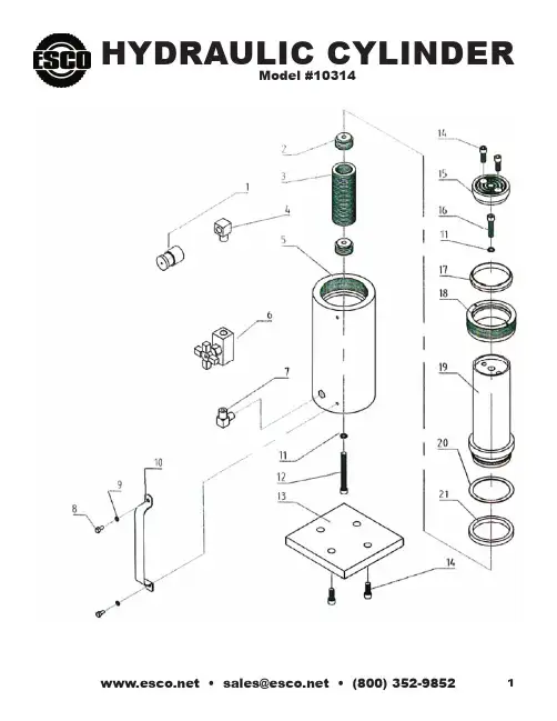
HYDRAULIC CYLINDERModel #10314•**************•(800)352-98521IMPORTANT RECEIVING INSTRUCTIONSVisually inspect all components for shipping damage. If any shipping damage isfound, notify carrier at once. Shipping damage is NOT covered by warranty. The carrieris responsible for all repair or replacement cost resulting from damage in shipment.SAFETY INFORMATIONWARNINGSTAY CLEAR OF LOADS SUPPORTED BY HYDRAULICS. A cylinder, when used as a load lifting device, should never be used as a load holding device. After the load has been raised,it should be blocked.WARNINGDO NOT EXCEED EQUIPMENT RATINGS.– – Never attempt to lift a load weighing more than the capacityof the cylinder. Overloading causes equipment failure andpossible personal injury.These cylinders are designed for a maximum pressure of10,000 psi (700 bar). Do not connect these cylinders to apump with a higher pressure rating.WARNINGBE SURE SETUP IS STABLE BEFORE LIFTING LOAD. – The cylinder should be placed on a flat surface that can support the load. Where applicable, use a cylinder base for added stability. Do not weld or otherwise modify the cylinder to attach a base or other support.– Avoid situations where loads are not directly centered on the cylinder plunger. Off-center loads produce considerablestrain on cylinders and plungers. In addition, the load may slip or fall, causing potentially dangerous results.– Distribute the load evenly across the entire saddle surface. Tilt saddles are available to reduce offset loading (except 100 ton models). Always use a saddle to protect the plungerwhen threaded attachments are not used.WARNINGUSE ONLY RIGID PIECES TO HOLD LOADS. Carefully select steel or wood blocks that are capable of supporting the load. Never use a hydraulic cylinder as a shim or spacer in any lifting or pressing application.WARNINGONLY USE HYDRAULIC CYLINDER IN ACOUPLED SYSTEM.Never use a cylinder with unconnected couplers. If the cylinder becomes extremely overloaded, the coupler check ball and/or hydraulic oil may shoot out of the cylinder causing severe personal injury.CAUTIONAVOID DAMAGING HYDRAULIC HOSE.– Avoid sharp bends and kinks when routing hydraulic hoses.Using a bent or kinked hose will cause severe back-pressure.Also, sharp bends and kinks will internally damage the hose leading to premature failure.– Do not drop heavy objects on hose. A sharp impact may cause internal damage to hose wire strands. Applyingpressure to a damaged hose may cause it to rupture.– Do not use the hydraulic hose to carry a hydraulic component(i.e. pumps, cylinders and valves).CAUTIONKEEP HYDRAULIC EQUIPMENT AWAY FROM FLAMES AND HEAT.Excessive heat will soften packings and seals, resulting in fluid leaks. Heat also weakens hose materials and packings. For optimum performance DO NOT expose equipment to temperatures of 150o F (65o C) or higher. Protect hoses and cylinders from weld spatter.INSTALLATION1. Make hydraulic connections. Use a pump with a releasevalve or a 3-way valve and one hose for single-actingcylinders (1). Use a pump with a 4-way valve and twohoses for double-acting cylinders (2).IMPORTANT: Double-acting cylinders must have bothcouplers connected.Fully hand-tighten all couplers. Loose coupler connections will block the flow ofoil between the pump and the cylinder.2. Remove air from the cylinder as shown below.Single-acting cylinders: Position the cylinder so that the plunger is pointed down andthe cylinder lower than the pump. Fully extend and retract the cylinder 2 or 3 times.Double-acting cylinders: Lay the cylinder on its side and have the couplersfacing up. Fully extend and retract the cylinder 2 or 3 times.NOTE: Collar threads are rated for the full capacity of the cylinder when fullyengaged in attachments.NOTE: The use of cylinder attachments or extensions reduces the cylinder capacity byat least 50%.OPERATIONWARNINGDO NOT HANDLE PRESSURIZED HOSES. Escaping oilunder pressure can penetrate the skin,causing serious injury. If oil is injected under the skin, see adoctor immediately.Operate the hydraulic pump to advance and retract the cylinder.Some single-acting cylinders are spring-return, others are load return. The speed ofretraction is affected by the length of the hose and other restrictions in the line. Double-acting cylinders are powered in both directions by the pump.The cylinder stop ring is designed to take the full load. However, to reduce cylinderwear, use less than full stroke when possible.MAINTENANCE1. Use dust caps when cylinders are disconnected from the hose. Keep entirecylinder clean to prolong cylinder life.2. Store cylinders up-right to prevent seal distortion.TROUBLE SHOOTINGThese cylinders should be repaired only by Authorized ESCO Technical ServiceCenters. Single-acting cylinders are spring loaded and require special disassemblytechniques to prevent personal injury.CAUSES PROBLEM POSSIBLE Cylinder will not advance.Pump release valve open.Coupler not fully tightened.Oil level in pump is low.Pump malfunctioning.Load is too heavy for cylinder.Cylinder advances part way.Oil level in pump is low.Coupler not fully tightened.Cylinder plunger binding.Cylinder advances in spurts.Air in hydraulic system.Cylinder plunger binding.Cylinder advances slower than normal.Leaking connection.Coupler not fully tightened.Pump malfunctioning.Cylinder advances but will not hold.Cylinder seals leaking.Pump malfunctioning.Leaking connection.Incorrect system set-up.Worn or damaged seals.Cylinder leaks oil.Internal cylinder damage.Loose connection.Pump release valve is closed.Cylinder will not retract or retracts slower than normal.Coupler not fully tightened.Pump reservoir over-filled.Narrow hose restricting flow.Broken or weak retraction spring.Cylinder damaged internally.Oil leaking from external relief valve.Coupler not fully tightened.Restriction in return line.EQUIPMENT SUPPY COMPANY15270 Flight Path Drive • Brooksville, Florida 34609Manufacturer of Equipment for Truck, Tractor, and Earth Mover Tire ChangingPhone 800/352-9852, 352/754-1117 • Fax 352/754-4508。
Y迷宫电刺激实验系统XR-XY1031使用说明书上海欣软信息科技有限公司联系电话:************手机:186****9316网址:目录一、Y迷宫电刺激实验系统简介: (3)二、系统构成 (3)三、系统特点 (3)四、系统技术指标 (4)五、测试原理与方法 (5)六、Y迷宫电刺激型测试与Y迷宫食物鉴赏型测试的转换5七、SuperShock刺激反射控制器使用说明 (6)八、系统规格 (10)九、装箱单细则 (10)一、Y迷宫电刺激实验系统简介:Y迷宫电刺激实验系统由Y电刺激装置和SuperShock刺激反射控制器(II 型)两部分组成。
其中Y电刺激装置适用于两种类型的Y迷宫交替实验,即可用于Y迷宫电刺激实验系统XR-XY1031型,又可用于Y迷宫食物鉴赏测试型XR-XY1032系统。
XR-XY1031为Y迷宫电刺激测试型,Y电刺激装置与SuperShock刺激反射控制器配套使用。
XR-XY1032为Y迷宫食物鉴赏测试型,Y电刺激装置与Y迷宫视频分析软件配套使用。
所谓Y形迷宫(Y maze)即为三等分辐射式迷宫,由三个支臂和一个连接区组成,三臂相互夹角为120°,每臂底部铺以不锈钢管,可与刺激电源相通。
各臂末端装有信号灯,信号灯开启指示该臂为安全区,即该臂底部不通电。
安全区的方位可随机变换,当某臂为安全区时,另两臂和连接区均带电,可训练动物学会主动逃避反应,逃向安全区。
已经应用在一系列神经行为为基础的学习记忆、有毒化学药品的毒性作用和新药或新疗法的效果研究中。
二、系统构成Y迷宫电刺激实验系统由Y电刺激装置、SuperShock刺激反射控制器(II型)及手操器三部分组成。
Y电刺激装置和SuperShock刺激反射控制器通过两条DB9传输电缆连接,手操器与SuperShock刺激反射控制器通过5米扁平传输电缆连接。
三、系统特点1.适用于两种类型Y迷宫交替实验A.Y迷宫食物鉴赏测试型XR-XY-1032B.Y迷宫电刺激测试型XR-XY-10312.电刺激栅无电击盲区,不露明线,三个臂设安全灯和手动插拔门3.可拆换的三臂侧插板,适用于啮齿动物变更新异环境自然习性的探究4.可移出的排泄物和和木屑托盘,易于清洗,消除示踪物对啮齿动物错误的行为诱导5.电刺激仪与摄像跟踪两种方法相互验证,提升对动物行为验证的准确性四、系统技术指标(一)、SuperShock刺激反射控制器技术指标1.4路输出、每路输出电流≤4mA,输出持续0-180S后自动切断刺激电压2.刺激电压频率:0.1~5Hz,步进量0.1Hz3.脉冲宽度:125mS4.声音时间间隔:0-60S自行连续设定5.预警输出时间间隔:0-60S自行连续设定6.电压输出时间间隔:0-180S自行连续设定7.安全灯亮度调整:0-10级自行连续设定8.声音强度调节:0-10级自行连续设定9.刺激电压强度变化范围:30-200V自行连续设定10.潜伏期连续计时范围:0-99.9s,分辨率100ms11.电源电压:交流220V±10%50Hz12.手操器面板键的设置和SuperShock刺激反射控制器相同,使用方法和SuperShock刺激反射控制器使用方法一样。
Y-1031一键备份使用说明书
一:外观示意图
二:连接示意图
三:注意事项
1.一键备份只能对应USB端口,而暂时未能对应其它端口
2.支持FAT32及NTFS档案系统
3.使用必须以电脑管理员身份安装JM_OTB应用软件,其它身份不能进行安装
4.为了正常备份和复原,请在操作之前先确认
四:软件安装
1.打开JM_OTB_v0_0_0_53软件安装包,双击“setup”进行安装,按提示操作直至安装结束,成功安装完成后会在桌面生成一个名为“OneTouchBackup”的图标。
2.打开桌面“OneTouchBackup”图标进入一键备份设置界面。
五:“OneTouchBackup”一键备份界面设置
此功能只支援拥有特殊按钮的外置硬盘装置,从此只需轻轻一按代替繁杂步骤。
(注意:进行一键备份之前,请先确认“OneTouchBackup”已在运行,第一次运行请按照以下“档案设置”及“设置”内容)
步骤一,运行“OneTouchBackup”,点击”档案备份”本地端“增加”选择添加需要备份的文件文档,“USB 装置”选取需要存储备份文件的目标磁盘或勾选USB装置磁盘原备份文件复原到本地电脑。
如图:
步骤二,”设定”勾选需要备份的文档文件类型及格式和界面语言设置
步骤三,选取设置完成需要备份的文档文件及文件格式以后在”档案备份”界面用鼠标点击“备份”、“复原”按钮或轻按产品上一键备份按钮,就会出现如下提示界面,
备份或复原完成后会自动关闭此界面。
注意:在复原文件时需要在”档案备份”界面里用鼠标点击“复原”才能成功复原文件。
六:常见问题解答
1.无法成功备份,请检查备份硬盘的剩余容量是否小于需要备份文件。
2.备份过程中突然停止,可能原因是硬盘存在坏道、克隆的数据有病毒、硬盘故障等情况,导致克隆失败。
3.为何XP系统下,超过2TB容量的硬盘无法识别,由于Windows XP最大支持硬
盘容量为2TB,建议更换Vista(64bit)及以上版本的操作系统即可支持,并建议将磁盘分区引导格式转换为GPT格式,否则操作系统不将不支持超过2TB的磁盘分区。