IPMI技术交流材料
- 格式:pdf
- 大小:472.03 KB
- 文档页数:24
技术交流经验会汇报材料
技术交流经验汇报材料
1. 引言:介绍所参与的技术交流活动的背景和目的。
2. 活动概述:对参与的交流活动进行简要概述,包括时间、地点、参与人员等信息。
3. 交流内容:详细描述所参与的技术交流活动的内容,包括讨论的主题、提出的问题、解决的方法等。
4. 交流收获:总结交流活动中所获取的收获和经验,包括新的技术知识、解决问题的思路、学习到的技术技巧等。
5. 参与感想:分享个人的参与感受和体会,包括与他人的交流互动、合作的体验、对技术水平的认识等。
6. 总结:对整个技术交流活动进行总结,强调其对个人技术提升和团队共享的重要性,提出进一步的改进和推广建议。
7. 后续计划:说明参与技术交流活动后的后续计划,包括进一步学习的方向、应用到实际工作中的具体计划等。
注意事项:
1. 文中不要出现标题相同的文字,避免重复。
2. 材料要简洁明了,重点突出,尽量使用清晰的语言表达。
3. 可以使用列表、图表等方式展示关键信息,提高阅读体验。
4. 可以适当添加交流活动中的图片、视频等素材,加强文档的可视化效果。
5. 结合个人经历和感受,展示自己的独特观点和实际收获,让读者更易于理解和接受。
文章标题:深度探讨IPM的设计、仿真和工艺流程制定IPM的设计、仿真和工艺流程制定是现代科技领域中的重要技术环节。
在这篇文章中,我们将从IPM的概念和原理、设计与仿真的关系、工艺流程制定的重要性以及相关职位的描述等几个方面展开全面的探讨。
1. IPM的概念和原理IPM,即集成电路制造过程,是指将芯片设计的数据转换为实际芯片的制造过程。
其原理是通过一系列的工艺步骤,如光刻、薄膜沉积、刻蚀等,将设计好的芯片结构逐步制造出来。
IPM的设计要考虑到工艺的可行性、成本和产能等因素,从而实现最佳的制造过程。
2. IPM的设计与仿真IPM的设计与仿真是高度相关的。
在设计阶段,需要进行工艺仿真,以验证设计的可行性和优化工艺参数。
仿真可以帮助发现潜在的制造问题,并提前做出调整,从而节约时间和成本。
设计人员还需要考虑到工艺制造的限制,以确保设计的可制造性。
3. 工艺流程制定的重要性工艺流程制定是IPM中至关重要的一环。
一个优秀的工艺流程可以提高芯片的性能和可靠性,降低制造成本。
工艺流程制定需要考虑到材料、设备、工艺参数等多方面因素,并进行合理的平衡和优化,才能实现高质量的芯片制造。
4. 相关职位描述在IPM的设计、仿真和工艺流程制定中,涉及到的相关职位包括芯片设计工程师、工艺工程师、工艺仿真工程师等。
他们需要具备丰富的专业知识和经验,能够熟练运用各种设计和仿真工具,以及制定合理的工艺流程。
个人观点和理解IPM的设计、仿真和工艺流程制定是集成电路制造领域中至关重要的技术环节。
它不仅对芯片的质量和性能有着直接的影响,同时也对整个制造过程的效率和成本有着重要的作用。
需要高水平的设计和仿真工程师,以及具备丰富经验的工艺工程师来保证IPM能够顺利进行和工艺流程能够成功制定。
总结回顾通过本文的探讨,我们对IPM的设计、仿真和工艺流程制定有了更深入的了解。
这些环节在集成电路制造中起着不可或缺的作用,需要全面的技术支持和合理的管理。
什么是BMC(基板管理控制器)?在BMC中完全實現IPMI功能需要一個功能強大的16位元或32位元微控制器以及用於數據儲存的RAM、用於非揮發性數據儲存的快閃記憶體和韌體。
一個提供IPMI v1.5的典型BMC大約需要32k RAM和128k快閃記憶體。
在這種情況下,伺服器可管理性的實現總成本(包括BMC chip、BMC 韌體和健康監視元件)將達40-50美元。
這麼高昂的成本將極大地限制IPMI協議在低成本伺服器和網路連接設備中的推廣應用。
采用IPMI協議的一種創新性解決方案是利用高性價比的迷你基板管理控制器,它在安全遠程重啟、安全重新上電、LAN警告和系統健康監視方面能提供基本的IPMI v1.5遠程可管理性。
由於性價比高,這款控制器還能用來管理網路設備,如公用桌上型電腦、印表機、集線器、數位電視視訊轉換盒等。
這種控制器是一種一站式解決方案,用戶無需做大量的韌體開發工作,因此能縮短新設計伺服器的面市時間。
另外,因為mBMC相容IPMI,因此它能應用於任何相容IPMI的遠程終端設備。
這種低成本控制器非常適合用於多種遠程管理,比如刀鋒型伺服器、公用桌上型電腦、印表機、集線器和家庭網路設備(網路閘道、數位視訊轉換盒)等。
mBMC會周期性地輪詢數位感測器來監視系統工作狀態,并通過SMBus介面與主機通訊,還提供一個用於本地系統管理、‘推進’警告和存取非揮發性記憶體的介面。
推進’警告用於從主機發送LAN警告到遠程終端以通知BIOS或作業系統產生的任何事件。
例如,緊急BIOS POST代碼可以通過LAN從典型的0×80 I/O埠重定向到遠程終端。
除了基本的IPMI功能和系統工作監視功能外,通過利用2個快閃記憶體之一儲存以前的BIOS,mBMC 還能實現BIOS快速元件的選擇和保護。
例如,在遠程BIOS升級後系統不能啟動時,遠程管理人員可以切換回以前工作的BIOS映像來啟動系統。
一旦BIOS升級後,BIOS映像還能被鎖住,可有效防止病毒對它的侵害。
MIM技术培训资料粉末冶金是将金属粉末制成产品的雏形,在通过烧结来实现产品的过程。
粉末冶金包含金属压制成型(PM)和金属注射成型(MIM)。
这里重点介绍粉末注射成型(MIM)01、MIM概述MIM即(Metal Injection Molding)是金属注射成型的简称。
是将金属粉末与粘结剂的增塑混合料注射于模型中的成形方法。
它是先将所选粉末与粘结剂进行混合,然后将混合料进行制粒再注射成形所需要的形状。
MIM流程结合了注塑成型设计的灵活性和精密金属的高强度和整体性,来实现极度复杂几何部件的低成本解决方案。
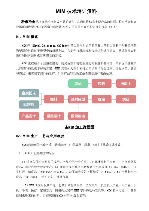
MIM流程分为四个独特加工步骤(混合造粒、注射成型、脱脂和烧结)来实现零部件的生产,针对产品特性决定是否需要进行表面处理。
▲MIM加工流程图02、MIM生产工艺与应用概要MIM制造流程一般包括:混料造粒、注塑成型、脱脂、烧结以及后续处理等。
(1)MIM工艺主要技术特点:1)适合各种粉末材料的成形,产品应用十分广泛;2)原材料利用率高,生产自动化程度高,适合连续大批量生产。
3)能直接成形几何形状复杂的小型零件(0.03g~200g);4)零件尺寸精度高(±0.01%~±0.5%),表面光洁度好(粗糙度1~5μm);5)产品相对密度高(95~98%),组织均匀,性能优异;(2)MIM的应用极其广泛,包括日常生活用品,诸如汽车、航空航天工业、军工业、手机、手表、医疗、家用器具、照相机及装有MIM零件的电动工具等。
MIM技术可适用于任何能制成粉末的材料,目前应用的MIM材料体系主要有:不锈钢、铁基合金、磁性材料、钨合金、硬质合金、精细陶瓷等系列。
03、MIM与其他加工工艺的比较(1)MIM与传统的粉末冶金(PM)的比较(2)MIM与精密铸造的比较压铸和精密铸造是可以成形三维复杂形状的零件,但压铸仅限于低熔点金属,而精密铸造(IC)限于合金钢、不锈钢、高温合金等高熔点金属及有色金属,对于难熔合金如硬质合金、高密度合金、金属陶瓷等却无能为力,这是IC的本质局限性,而且IC对于很小、很薄、大批量的零件生产是十分困难或不可行的。
第二章 IPMC 的制备新型智能材料IPMC (Ion-exchange polymer membrane metal composite )是离子型电致动聚合物EAP (electroactive polymer )的一种。
它中间层是基体膜,两边为贵金属电极(如铂电极)。
目前基体膜主要有DuPont 公司的Nafion TM 膜和日本的Flemion 膜、Selemion 膜[54]。
这三种膜中最常用的是DuPont 公司的Nafion TM 膜。
本文中IPMC 是通过采用杜邦公司的Nafion 溶液来浇铸出基底膜,然后经过化学镀在基底膜的两侧沉积铂粒的方式制备而成的。
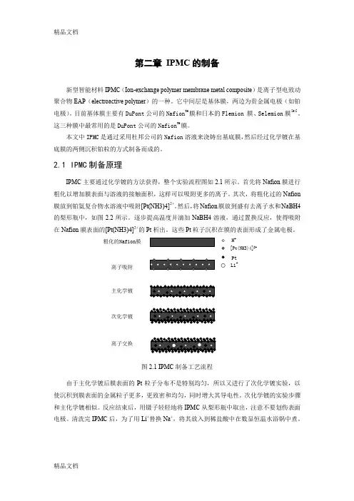
2.1 IPMC 制备原理IPMC 主要通过化学镀的方法获得,整个实验流程图如2.1所示。
首先将Nafion 膜进行粗化以增加膜表面与溶液的接触面积,这样可以吸附更多的离子。
其次,将粗化过的Nafion 膜放到铂氨复合物水溶液中吸附[Pt(NH3)4]2+。
然后,将Nafion 膜放到盛有去离子水和NaBH4的梨形瓶中,如图2.2所示。
逐步提高温度并滴加NaBH4溶液,通过置换反应,使得吸附在Nafion 膜表面的[Pt(NH3)4]2+的Pt 析出。
这些Pt 粒子沉积在膜的表面形成了金属电极。
粗化的Nafion 膜H +[Pt(NH3)4]2+离子吸附Pt 主化学镀次化学镀离子交换Li+图2.1 IPMC 制备工艺流程由于主化学镀后膜表面的Pt 粒子分布不是特别均匀,所以又进行了次化学镀实验,以使沉积到膜表面的金属粒子更多,更致密和均匀,同时增大其导电性。
次化学镀的实验步骤和主化学镀相似。
反应结束后,用镊子轻轻地将IPMC 从梨形瓶中取出,注意不要划伤表面电极。
清洗完IPMC 后,为了用Li +替换Na +,将其放入到稀盐酸中在数显恒温水浴锅中煮。
图2.2 IPMC化学镀装置主化学镀的化学还原反应公式为(2-1)(2-2)(2-3)。
什么是BMC(基板管理控制器)?在BMC中完全實現IPMI功能需要一個功能強大的16位元或32位元微控制器以及用於數據儲存的RAM、用於非揮發性數據儲存的快閃記憶體和韌體。
一個提供IPMI v1.5的典型BMC大約需要32k RAM和128k快閃記憶體。
在這種情況下,伺服器可管理性的實現總成本(包括BMC chip、BMC 韌體和健康監視元件)將達40-50美元。
這麼高昂的成本將極大地限制IPMI協議在低成本伺服器和網路連接設備中的推廣應用。
采用IPMI協議的一種創新性解決方案是利用高性價比的迷你基板管理控制器,它在安全遠程重啟、安全重新上電、LAN警告和系統健康監視方面能提供基本的IPMI v1.5遠程可管理性。
由於性價比高,這款控制器還能用來管理網路設備,如公用桌上型電腦、印表機、集線器、數位電視視訊轉換盒等。
這種控制器是一種一站式解決方案,用戶無需做大量的韌體開發工作,因此能縮短新設計伺服器的面市時間。
另外,因為mBMC相容IPMI,因此它能應用於任何相容IPMI的遠程終端設備。
這種低成本控制器非常適合用於多種遠程管理,比如刀鋒型伺服器、公用桌上型電腦、印表機、集線器和家庭網路設備(網路閘道、數位視訊轉換盒)等。
mBMC會周期性地輪詢數位感測器來監視系統工作狀態,并通過SMBus介面與主機通訊,還提供一個用於本地系統管理、‘推進’警告和存取非揮發性記憶體的介面。
推進’警告用於從主機發送LAN警告到遠程終端以通知BIOS或作業系統產生的任何事件。
例如,緊急BIOS POST代碼可以通過LAN從典型的0×80 I/O埠重定向到遠程終端。
除了基本的IPMI功能和系統工作監視功能外,通過利用2個快閃記憶體之一儲存以前的BIOS,mBMC 還能實現BIOS快速元件的選擇和保護。
例如,在遠程BIOS升級後系統不能啟動時,遠程管理人員可以切換回以前工作的BIOS映像來啟動系統。
一旦BIOS升級後,BIOS映像還能被鎖住,可有效防止病毒對它的侵害。

IPM(Intelligent Power Module)是一种集成了多种功能的电源模块,用于驱动电机、进行电源转换和电流控制等应用。
其封装工艺是确保模块内部电路的可靠性和稳定性的重要环节。
以下是IPM封装的流程培训资料:一、设计封装1.根据IPM模块的功能和特性,设计合适的封装结构和尺寸。
2.考虑封装内部的电路布局、元器件的排布以及互连方式。
3.确保设计的封装能够保护电路免受环境因素(如温度、湿度、机械应力等)的影响。
4.考虑到可制造性,确保设计易于生产且良品率高。
二、制作模具1.根据设计要求,制作用于封装制造的模具。
2.确保模具精度高,以减小封装过程中产生的误差。
3.对模具进行测试和验证,确保其符合设计要求。
三、封装制造1.将IPM模块的内部电路和元器件按照设计要求放置在模具中。
2.使用适当的材料和工艺(如塑料、陶瓷等)对模块进行封装。
3.进行必要的焊接和互连操作,确保元器件与电路的可靠连接。
4.进行各项性能测试,确保封装后的模块功能正常。
四、质量检测1.对封装后的IPM模块进行外观检查,确保没有明显的缺陷或问题。
2.进行一系列的电气测试,如耐压测试、绝缘电阻测试等,确保模块的电气性能符合要求。
3.进行环境适应性测试,如温度循环、湿度敏感度等,以确保模块能够在各种环境下稳定工作。
4.对不合格品进行筛选和处理,防止不良品流入市场。
五、文档整理与培训1.整理封装流程的相关资料和技术文档,包括设计图纸、测试报告等。
2.对参与封装的员工进行培训,使其熟悉封装流程和相关技术要求。
3.制定相应的操作规程和质量标准,确保生产过程中的一致性和规范性。
通过以上培训资料,参与封装的员工可以更好地了解IPM封装流程的相关知识和技能,从而保证IPM模块的封装质量和可靠性。
ipm封装流程培训资料 -回复"IPM封装流程培训资料"的主题是关于IPM (Integrated Pest Management,综合有害生物管理)封装流程的培训资料。
IPM是一种综合性的有害生物管理方法,旨在最小化对环境和人类的危害,同时有效地控制农作物和害虫之间的关系。
在本文中,我们将逐步回答有关IPM封装流程的问题,并提供相应的培训资料,以帮助读者更好地理解和应用IPM技术。
第一部分:IPM概述首先,我们将介绍I PM的基本概念和原则。
IPM是一种综合性的农业管理方法,旨在减少对化学农药的依赖,并采用多种技术手段来控制农作物上的害虫和病害。
IPM通过综合应用生物学、生态学、化学和遗传学等知识,使农作物能够与害虫建立一种平衡的关系,从而实现可持续的农业生产。
第二部分:IPM封装流程的重要性接下来,我们将探讨IPM封装流程的重要性。
IPM封装流程是IPM实施过程中的关键环节,它使得农业生产者能够系统地应用I P M原则,并确保最佳的效果。
封装流程涉及到害虫监测、阈值设定、决策制定和评估等步骤,这些步骤能够帮助农作物管理人员在防治害虫时做出正确的决策。
第三部分:IPM封装流程培训资料的内容现在我们将详细介绍IPM封装流程培训资料的内容。
这些资料将提供以下内容:1. IPM封装流程的基本原则:介绍IPM封装流程的基本原则,包括害虫监测、阈值设定、决策制定和评估。
2. 害虫监测方法:详细介绍害虫监测的不同方法,包括使用猎捕器具进行野外监测、摄像头监测、诱虫和树干粘虫板等。
培训资料将提供实际案例和示范,以帮助农作物管理人员有效地监测害虫。
3. 阈值设定方法:指导农作物管理人员如何设定阈值。
培训资料将介绍不同作物和害虫的阈值设定方法,并提供具体案例进行解读。
4. 决策制定方法:培训资料将介绍如何根据害虫监测和阈值设定的结果来制定合适的决策。
这包括选择合适的防治措施,确定施药时间和剂量,以及进行害虫防治方案的调整等。
- IPMI -Addenda, Errata, and Clarifications Intelligent Platform Management Interface Second Generation Specificationv2.0, revision 1.0 Intelligent Platform Management InterfaceSpecificationv1.5, revision 1.1Addendum Document Revision 32/15/06Addenda, Errata, and ClarificationsCopyright © 2002, 2003, 2004, 2005, 2006 Intel Corporation, Hewlett-Packard Company,NEC Corporation, Dell Inc., All rights reserved.INTELLECTUAL PROPERTY DISCLAIMERTHIS SPECIFICATION IS PROVIDED “AS IS” WITH NO WARRANTIES WHATSOEVER INCLUDING ANY WARRANTY OF MERCHANTABILITY, FITNESS FOR ANY PARTICULAR PURPOSE, OR ANY WARRANTY OTHERWISE ARISING OUT OF ANY PROPOSAL, SPECIFICATION, OR SAMPLE.NO LICENSE, EXPRESS OR IMPLIED, BY ESTOPPEL OR OTHERWISE, TO ANY INTELLECTUAL PROPERTY RIGHTS IS GRANTED OR INTENDED HEREBY.INTEL, HEWLETT-PACKARD, NEC, AND DELL DISCLAIM ALL LIABILITY, INCLUDING LIABILITY FOR INFRINGEMENT OF PROPRIETARY RIGHTS, RELATING TO IMPLEMENTATION OF INFORMATION IN THIS SPECIFICATION. INTEL, HEWLETT-PACKARD, NEC, AND DELL, DO NOT WARRANT OR REPRESENT THAT SUCH IMPLEMENTATION(S) WILL NOT INFRINGE SUCH RIGHTS.I2C is a trademark of Philips Semiconductors. All other product names are trademarks, registered trademarks, or servicemarks of their respective owners.I2C is a two-wire communications bus/protocol developed by Philips. IPMB is a subset of the I2C bus/protocol and was developed by Intel. Implementations of the I2C bus/protocol or the IPMB bus/protocol may require licenses from various entities, including Philips Electronics N.V. and North American Philips Corporation.Intel, Hewlett-Packard, NEC, and Dell retain the right to make changes to this document at any time, without notice. Intel, Hewlett-Packard, NEC, and Dell make no warranty for the use of this document and assumes no responsibility for any error which may appear in the document nor does it make a commitment to update the information contained herein.2Addenda, Errata, and ClarificationsContents Introduction (6)Errata Numbers (6)Revision 1 (6/1/04) Addenda, Errata, and Clarifications (7)E269(See 2/15/06 Addenda, Errata, and Clarifications, below) (7)E329Errata - Table 13-8, RMCP/RMCP+ Packet Format for IPMI via Ethernet (7)E330Clarification - Table 42-3, Sensor Type Codes (7)E331Clarification/Typo - Table 22 18, Cipher Suite Record Format (8)E332Errata - Table 44-11, Command Number Assignments and Privilege Levels (8)E333Addendum - Table 43 15, Sensor Unit Type Codes (8)E334Typo - Table 44-11, Command Number Assignments and Privilege Levels (9)E335Errata and Clarification - Table 3-1, Required BMC Functions (9)E336Errata - Table 44-11, Command Number Assignments and Privilege Levels (9)E337Clarification - Section 32.3, OEM SEL Record - Type E0h-FFh (10)E338Clarification - Section 22.10, Get BT Interface Capabilities Command - applies to IPMI v1.5 and v2.0 (10)E339Addendum - Table 25-4, Serial/Modem Configuration Parameters (11)E340Clarification - Figure 9-8, Aborting KCS Transactions in-progress and/or Retrieving KCS Error Status (11)E341Addendum - Table 30-9, Alert Immediate Command, and Table H-1, Sub-function Number Assignments (13)E342Addendum - Table 42-3, Sensor Type Codes (14)E344Errata - Table 36-3, Sensor Type Codes, Missing Errata E256 (14)E345Errata - Table 17-1, PEF Action Priorities (15)E346Clarification - Section 13.31.4, Integrity Algorithms, Table 22-30, Set Channel Security Keys (15)E347Addendum and Clarification - Table 22-17, Get Channel Cipher Suites Command (16)E348Typos (17)E349Errata - Table 22-12, Get System Interface Capabilities Command (17)E350Errata and Clarification - Table 13-21, xRC4-Encrypted Payload Fields (17)E351Errata - Table C3-1, Service Processor Management Interface Description Table Format (applies to IPMI v1.5 & v2.0) (18)E352Addendum - Table 43-13, Entity ID Codes (18)E353Addendum - (applies to IPMI v1.5 only) (19)E354Clarification - Table 43-13, Entity ID Codes (19)E355Clarification - Table 22-30, Set Channel Security Keys Command (19)E356Errata - Section 6.12.8, Session Sequence Numbers (20)E357Addendum and Clarification - Table 36-3, Sensor Type Codes (22)E358Addendum and Clarification - Table 30-9, Alert Immediate Command (23)E359Addendum - Section 17.7, Event Filter Table and Table 30-2, Get PEF Capabilities Command..24 E360Addendum - Section 21, Firmware Firewall & Command Discovery Commands (27)E361Typos and Clarifications - Section 13.28, Authentication, Integrity, and Confidentiality Algorithm Numbers (32)E362Typos and Clarifications - Section 13.31, RMCP+ Authenticated Key-Exchange Protocol (RAKP)323Addenda, Errata, and ClarificationsE366Errata - Table 22-35, Set User Password Command (35)Revision 2 (5/5/05) Addenda, Errata, and Clarifications (36)E363Typo, Table 5-4, System Software IDs (36)E364Clarification - Table 22-17, Get Channel Cipher Suites Command (36)E365Typos - Tables 21-7, -8, -9 (36)E367 Addendum - Table 24-2, Activate Payload Command, Table 15-2, SOL Payload Data Format (37)E368Typos - Section 21, Firmware Firewall & Command Discovery Commands (39)E370Clarification - Table 32-1, SEL Event Records (41)E372Addendum - “settable sensors” (42)E373Addendum - Table 42-3, Sensor Type Codes (46)E374Addendum - Table 28-3, Get Chassis Status Command (47)E375Addendum - Table 42-3, Sensor Type Codes (47)E376Addendum - Table 42-3, Sensor Type Codes (47)E377Clarification - Section 20.1, Get Device ID Command, & Table 20-2, Get Device ID Command (48)E378Addendum - Set Serial Routing Mux command (49)E379Addendum - Command Forwarding (50)E380Addendum - Table 25-4, Serial/Modem Configuration Parameters (57)E381Addendum - Set / Get System Info Command (58)E382Clarification - Table 21-2, Get NetFn Support Command (62)E383Clarification - Table 23-4, LAN Configuration Parameters (63)E384Clarification - Table 27-3, Set Watchdog Timer Command, Table 27-4, Get Watchdog Timer Command (64)E385Clarification/Errata - Section 13.28.4, Integrity Algorithms (65)E386Clarification - Table 22-26, Get AuthCode Command (65)Revision 3 (2/15/06) Addenda, Errata, and Clarifications (67)E269Addendum and Clarification - Table 22-32, Get User Access Command (67)E387Addendum - Table 22-24, Close Session Command (68)E388Typos - Section 6.13.2, Send Message Command From System Interface, and Table 28-14, Boot Option Parameters (69)E389Errata - Table 24-7, Get Payload Instance Info Command (70)E390Addendum and Clarification - Table 43-13, Entity ID Codes (70)E391Addendum - Section 6.13.4, Bridged Request Example (70)E392Addendum - Table 42-3, Sensor Type Codes (71)E393Typo - Table 43-13, Entity ID Codes (71)E394Addendum - Table 23-2, Set LAN Configuration Parameters Command, Table 26-3, Set SOL Configuration Parameters Command, Table 30-4, Set PEF Configuration Parameters Command72 E395Errata - Table 43-13, Entity ID Codes (72)E396Addendum and Clarification on E372 “Settable Sensors” (73)E397Addendum - Get / Set SEL Time UTC Offset Commands (73)E398Addendum - Additional Completion Code for Section 35b.4, Forwarded Command Command75 E399Clarification - Table 22-2, Set BMC Global Enables Command, Table 22-3, Get BMC Global Enables Command (76)E400Addendum - Writable SDRs Optional (77)E401Addendum and Clarification - Table 22-25, Get AuthCode Command (79)4Addenda, Errata, and ClarificationsE402Addendum - Table 42-3, Sensor Type Codes (80)E403Addendum - Table 23-4, LAN Configuration Parameters (81)E404Addendum and Clarification - Section 1.2, Reference Documents, 20.8, Get Device GUID Command, and 22.14, Get System GUID Command (81)E405Addendum - Section 1.2, Reference Documents (82)E406Clarification - Table 22-15, Get Channel Authentication Capabilities Command (82)E407Addendum - Table 13-15, RMCP+ and RAKP Message Status Codes (83)E408Addendum and Clarification - Table 13-10, RMCP+ Open Session Response, RAKP Message 3 error handling (84)E409Addendum - Additional IPMI Channel Number support (85)E410Addendum - Table 35b-5, Forwarded Command Command (96)E411Clarification and Errata - 15.11 SOL Packet Acknowledge and Retries (97)5Addenda, Errata, and ClarificationsIntroductionThis document presents errata and clarifications applying to the Intelligent Platform Management Interface Specification Second Generation Specification, v2.0, revision 1.0, and Intelligent Platform Management Interface Specification v1.5, revision 1.1. For the IPMI v1.5 Specification, this errata document picks up where the IPMI v1.5 Addenda, Errata, and Clarifications document, revision 5 document left off.As of this writing the IPMI specifications are available from the IPMI Web Site at:/design/servers/ipmiThe section, table, and figure references are given relative to the given revision of the specification, unless otherwise noted. Where examples are given, text additions are shown with double underlines, and text deletions are shown with strike-through.Unless noted, errata apply to IPMI v2.0 only.Errata NumbersThe errata numbers pick up from where numbers for previous errata documents left off. This is done to help avoid confusion when referring to errata across revisions of the specification and errata documents. Some errata numbers are skipped in this document. This is intentional. The errata numbers are derived from numbers used for tracking errata and clarification requests within the IPMI Promoters group. The gaps in the sequence result from requests that have been dropped or that are still in progress.6Addenda, Errata, and Clarifications7Revision 1 (6/1/04) Addenda, Errata, and ClarificationsE269 (See 2/15/06 Addenda, Errata, and Clarifications, below) .E329 Errata - Table 13-8, RMCP/RMCP+ Packet Format for IPMI via Ethernet The lengths of the Pad Length and Next Header fields were missing in the in RMCP+ column of the table. This has been corrected as follows:Table 13-8, RMCP/RMCP+ Packet Format for IPMI via EthernetFormatFieldRMCP /IPMI 1.526Fh ASF RMCP 298h RMCP / IPMI 2.0 “RMCP+” 26Fh Value …Pad Length 1 1 indicates how many pad bytes were added so that theamount of non-pad data can be determined.Next Header1 1 Reserved in IPMI v2.0. Set to always = 07h for RMCP+packets defined in this specification. …E330 Clarification - Table 42-3, Sensor Type Codes The naming for Offset 05h in the Physical Security sensor as "Unauthorized dock/undock" was ambiguous regarding what state would be reported. This has been clarified as follows:Table 42-3, Sensor Type CodesSensor Type Sensor Type Code Sensor-specific Offset EventPhysical Security (ChassisIntrusion) 05h 00h 01h 02h 03h General Chassis Intrusion Drive Bay intrusionI/O Card area intrusionProcessor area intrusion04h LAN Leash Lost (system is unplugged from LAN)The Event Data 2 field can be used to identify which networkcontroller the leash was lost on where 00h corresponds to thefirst (or only) network controller.05h 06h Unauthorized dockFAN area intrusion (supports detection of hot plug fan tampering)Addenda, Errata, and Clarifications8E331 Clarification/Typo - Table 22 18, Cipher Suite Record Format The table has been updated to correct typos and clarify that the first field of the Cipher Suite Record starts with either a C0h or C1h byte, followed by one or more ID bytes depending on whether the Cipher Suite is a standard or OEM Cipher Suite, respectively.Table 22-18, Cipher Suite Record Format size Tag bits [7:6] Tag bits [5:0]2 or 5 - This field starts off with either a C0h or C1h "Start of Record" byte, depending on whether theCipher Suite is a standard Cipher Suite ID or an OEM Cipher Suite, respectivelyByte 1:[7:0] = 1100_0000b. Start of Record, Standard Cipher SuiteData following C0h (1100_0000b) start of record byte:Byte 2 - Cipher Suite IDThis value is used a numeric way of identifying the Cipher Suite on the platform. It’s used incommands and configuration parameters that enable and disable Cipher Suites. See Table 22-19, Cipher Suite IDs.[5:0] = 1100_0001b. Start or Record, OEM Cipher SuiteData following C1h (1100_0001) start of record byte:Byte 2 - OEM Cipher Suite IDSee Table 22-19, Cipher Suite IDs.Byte 3:5 - OEM IANA Least significant byte first. 3-byte IANA for the OEM or body that defined the Cipher Suite.E332 Errata - Table 44-11, Command Number Assignments and Privilege Levels Incorrect privilege level definition for Activate/Deactivate Payload commands. Table 44-11, Command Number Assignments and Privilege Levelssection NetFn CMD C U O A … Activate Payload24.1 App 48h [10] [10] [10] Deactivate Payload 24.2 App 49h [10] [10] [10]…10. The configuration parameters for a given payload type determine the privilege level required to activate /deactivate the payload.E333 Addendum - Table 43 15, Sensor Unit Type Codes The IPMI Units table was missing 'grams' as one of the measurement units. In addition, Fatal Errors (which are a special class of uncorrectable error in some bus implementations) were not included. These units have been added to the table as follows:Table 43-15, Sensor Unit Type Codes…Addenda, Errata, and Clarifications9 23minute 57 becquerel 91 fatal error 24 hour 58 PPM (parts/million) 92 grams…E334 Typo - Table 44-11, Command Number Assignments and Privilege Levels Table 44-11. Command Number Assignments and Privilege Levels had a bad cross-reference. It states that “Set User Access” is in section 22.25, but it isn’t. Section 22.25 is “Set Channel Security Keys Command”. Section 22.26 is the “Set User Access Command”.E335 Errata and Clarification - Table 3-1, Required BMC Functions There was a 'cut and paste' error in the specification where text from the SDR Repository requirements was copied to the SEL Interface requirements. This has been corrected by deleting the erroneous text as follows. In addition, since the SEL is critical to post-mortem failure analysis, it is required to be accessible whenever the BMC is accessible. This requirement is also included in the update to table 3-1.Table 3-1, Required BMC Functions…SEL Interface M The BMC must provide a System Event Log interface. The event log must holdat least 16 entries. SEL access must be provided via the system interface. TheSEL must be fully accessible via all mandatory SEL commands through allsupported interfaces to the BMC whenever the system is powered up or inACPI 'S1' sleep state. SEL read access is always mandatory whenever theBMC is accessible, and through any interface that is operational, regardless ofsystem power state. .-…E336 Errata - Table 44-11, Command Number Assignments and Privilege Levels The specification was missing the command number assignments for Firmware Firewall commands. These are defined as follows:Table 44-11, Command Number Assignments and Privilege Levelssection NetFn CMD C U O A IPM Device “Global” Commands …Get NetFn Support 21.2 App 09h XGet Command Support 21.3 App 0Ah XGet Command Sub-function Support 21.4 App 0Bh XGet Configurable Commands 21.5 App 0Ch XGet Configurable Command Sub-functions 21.6 App 0Dh Xunassigned - App 0Eh-0Fh - - - - Set Command Enables 21.7 App 60h XGet Command Enables 21.8 App 61h XSet Command Sub-function Enables 21.9 App 62h XGet Command Sub-function Enables 21.10 App 63h X…Addenda, Errata, and Clarifications10 E337 Clarification - Section 32.3, OEM SEL Record - Type E0h-FFh An OEM ID is not part of the record. As with other OEM commands and operations, the OEM ID for the record is inferred from the Get Device ID command. Since the record has no mechanism for returning which controller or software logged the record, the ID must be presumed to be the MFR ID from the Get Device ID command to the BMC.32.3 OEM SEL Record - Type E0h-FFhE0h - FFh Range reserved for non-timestamped OEM SEL records. The SEL Device does not automaticallytimestamp these records. The four bytes passed in the byte locations normally used for the timestampwill be directly entered into the SEL . SEL viewer applications should not interpret byte positions 4:7in this record as a timestamp . These records are entered via the Add SEL or Partial Add SELcommands.Note that an OEM ID is not part of this record. Since the record also has no mechanism for returningwhich controller or software logged the record, the OEM ID for this record is presumed to be the MFRID from the Get Device ID command to the BMC.E338 Clarification - Section 22.10, Get BT Interface Capabilities Command - applies to IPMI v1.5 and v2.0This applies to both IPMI v1.5 and v2.0. (For IPMI v1.5 this is for section 18.9.) The size definitions for bytes 3 and 4 was ambiguous / misleading. The names implied that the value was returning the size of the buffer (i.e. how many bytes a driver could write to the interface) when instead the value was returning the maximum 'message payload' size that could be accepted. This is clarified as follows: 22.10 Get BT Interface Capabilities CommandThe BT interface includes a Get BT Interface Capabilities command that returns various characteristics of the interface, including buffer sizes, and multithreaded communications capabilities.Table 22-13, Get BT Interface Capabilities Command byte data fieldRequest Data - -Response Data 1 Completion Code2 Number of outstanding requests supported (1 based. 0 illegal)3 Input (request) buffer message size in bytes. (1 based.)[1]4 Output (response) buffer message size in bytes. (1 based.)[1]5 BMC Request-to-Response time, in seconds, 1 based. 30 seconds,maximum.6 Recommended retries (1 based). (see text for BT Interface)1. For Bytes 3 and 4 (Input and Output Buffer size), the buffer message size is thelargest value allowed in first byte (length field) of any BT request or responsemessage. For a send, this means if Get BT Interface Capabilities returns 255 inbyte 3 (input buffer size) the driver can actually write 256 bytes to the input buffer(adding one for the length byte (byte 1) that is sent in with the request.)E339 Addendum - Table 25-4, Serial/Modem Configuration ParametersA new, optional, parameter is defined to help speed software detection of bit rate support for the channel. This parameter is specified as follows:Table 25-4, Serial/Modem Configuration Parameters Parameter # Parameter Data (non-volatile unless otherwise noted)[1]…Bit Rate Support (READ ONLY, optional) 50 This parameter returns a read-only bitfield indicating which bit rates are supported for thisserial channel.data 1 - Bit Rate Support[7:6] - reserved[4] - 115.2 kbps[3] - 57.6 kbps[2] - 38.4 kbps[1] - 19.2 kbps (required)[0] - 9600 bps…E340 Clarification - Figure 9-8, Aborting KCS Transactions in-progress and/or Retrieving KCS Error StatusThe block labelled "Write READ dummy byte to DATA_IN, phase=error3" can be confusing. The READ control code value (68h) must be written, not just any 'dummy' data byte. This is clarified as follows:Figure 9-8, Aborting KCS Transactions in-progress and/or Retrieving KCS Error Statusaccess only.BMC sets status to READ_STATE and writesthe error status byte tothe DATA_OUT register.E341 Addendum - Table 30-9, Alert Immediate Command, and Table H-1, Sub-function Number AssignmentsThe Alert Immediate command works well for testing alerts, but it cannot effectively be used for generating events that contain event data. The command is extended to allow event data to be delivered with the alert, and table H-1 is updated to allow reporting of this optional capability as a sub-function.Table 30-9, Alert Immediate CommandBytefielddata…3 Alert String SelectorSelects which Alert String, if any, to use with the alert.[7] - 0b = don’t send an Alert String1b = send Alert String identified by following string selector.[6:0] - string selector.000_0000b = use volatile Alert String.01h-7Fh = non-volatile string selector.The following “Platform Event Parameters” ( bytes 4:11) can be used to fill inthe corresponding event data fields of a Platform Event Trap. Whensupported, all bytes (4:11) must be supplied. Implementation of thiscapability is OPTIONAL but highly recommended for IPMI v2.0implementations. See Table 29-5, Event Request Message Fields, forspecification of the individual fields.4 Generator ID5 EvMRev6 Sensor Type7 Sensor #8 Event Dir | Event Type9 Event Data 110 Event Data 211 Event Data 3Response Data 1 Completion Code. Generic codes, plus following command-specificcompletion codes:81h = Alert Immediate rejected due to alert already in progress.82h = Alert Immediate rejected due to IPMI messaging session active on thischannel.83h = Platform Event Parameters (4:11) not supported.…Table H-1, Sub-function Number AssignmentsSubFn # NetFn CMD…Immediate S/E 16h Alertreserved / unspecified 0Alert to Channel 1 1Alert to Channel 2 2Alert to Channel 3 3Alert to Channel 4 4Alert to Channel 5 5Alert to Channel 6 6Alert to Channel 7 7Platform Event Parameters 8…E342 Addendum - Table 42-3, Sensor Type CodesThe specification primarily covers events for failures related to OS Hangs and startup, but did not cover events for 'normal' OS shutdown or if a power down or reset occurs that is not related to a BMC or pushbutton initiated power down or resets. The specification also did not cover whether of not the soft-shutdown was initiated by PEF, or if a shutdown that was requested via a local s/w agent failed. This is addressed with the following additions:Table 42-3, Sensor Type CodesSensor Type SensorTypeCodeSensor-specificOffset Event…System Boot / Restart Initiated 1Dh 00h Initiated by power up (this would typically be generated byBIOS/EFI)01h Initiated by hard reset (this would typically be generated byBIOS/EFI)02h Initiated by warm reset (this would typically be generated byBIOS/EFI)03h04hUser requested PXE bootAutomatic boot to diagnostic05h OS / run-time software initiated hard reset06h OS / run-time software initiated warm reset07h System Restart (Intended to be used with Event Data 2 and or 3as follows:)Event Data 2[7:4] - reserved[3:0] - restart cause per Get System Restart Cause command.Event Data 3Channel number used to deliver command that generatedrestart, per Get System Restart Cause command.…OS Stop / Shutdown 20h 00h Critical stop during OS load / initialization. Unexpected errorduring system startup. Stopped waiting for input or powercycle/reset.01h Run-time Critical Stop (a.k.a. ‘core dump’, ‘blue screen’)02h OS Graceful Stop (system powered up, but normal OS operationhas shut down and system is awaiting reset pushbutton, power-cycle or other external input)03h OS Graceful Shutdown (system graceful power down by OS)04h Soft Shutdown initiated by PEF05h Agent Not Responding. Graceful shutdown request to agent viaBMC did not occur due to missing or malfunctioning local agent.E344 Errata - Table 36-3, Sensor Type Codes, Missing Errata E256IPMI v1.5 Errata revision 5, E256 - the offset for “Addendum - Timestamp Synch Event" was missed in v2.0 rev 1.0 of the specification. (The note associated with the offset was already part in the spec, however.) This is corrected as follows. The note associated with the offset was already part in the spec.Table 36-3, Sensor Type Codes…System Event 12h 00h ……05hTimestamp Clock Synch.This event can be used to record when changes are made to thetimestamp clock(s) so that relative time differences between SELentries can be determined. See note [1].Event Data 2[7] - first/second0b = event is first of pair.1b = event is second of pair.[6:4] - reserved[3:0] - Timestamp Clock Type0h = SEL Timestamp Clock updated. (Also used when bothSEL and SDR Timestamp clocks are linked together.)1h = SDR Timestamp Clock updated.…E345 Errata - Table 17-1, PEF Action PrioritiesThe priority for ICMB Group Control Operation as a PEF action was not listed in PEF Priority Table. This is corrected as follows:Table 17-1, PEF Action PrioritiesAction PriorityAdditionalInformationpower down 1 (optional)power cycle 2 (optional) Will not be executed if a power downaction was also selected.reset 3 (mandatory) Will not be executed if a power down orpower cycle action was also selected.Diagnostic Interrupt 4 (optional) The diagnostic interrupt will not occur if ahigher priority action is also selected to occur.ICMB Group Control 5 (optional) Performs ICMB group control operationaccording to settings from the Group Control Tableparameter in the PEF Configuration Parameters.Send Alert 6 (mandatory if alerting is supported) Send alerts inorder based on the selected Alert Policy.Alert actions will be deferred until after the powerdown has completed.There is an additional prioritization within alertsbeing sent: based on the Alert Policy Table entriesfor the alert. This is described further in Section17.11, Alert Policy Table.OEM OEM (optional) Priority determined by OEM.E346 Clarification - Section 13.31.4, Integrity Algorithms, Table 22-30, Set Channel Security KeysThe size of K G (160 bits) was not explicitly defined, nor were the sizes of K G and K R parameters called out in the Set Channel Security Keys command. In addition, a recommendation has been added to indicate that a 160-bit user key should be used when “one-key” logins are used. This has been clarified with additions to section 13.31.4 and 22.25 as follows:13.31.4 Integrity AlgorithmsThe Integrity Algorithm Number specifies the algorithm used to generate the contents for the AuthCode “signature”field that accompanies authenticated IPMI v2.0/RMCP+ messages once the session has been established.Unless otherwise specified, the integrity algorithm is applied to the packet data starting with the AuthType/Format field up to and including the field that immediately precedes the AuthCode field itself.HMAC-SHA1-96 and HMAC-MD5-128 utilize the Session Integrity Key as the key for use in HMAC. For “two key” logins, 160-bit key K G is used in the creation of SIK. For “one key” logins, the user’s key (password) is used in place of K G. To maintain a comparable level of authentication, it is recommended that a full 160-bit user key be used when “one key” logins are enabled for IPMI v2.0/RMCP+.Table 22-30, Set Channel Security Keys Commanddatafieldbyte…ID3 Key[7:0] - key ID.00h = RMCP+ “K R” key (20 bytes). The “K R”key is used as a unique value forrandom number generation. Note: A BMC implementation is allowed toshare a single K R value across all channels. A utility can set K R andlock it for one channel, and then verify it has been set and locked forany other channels by using this command to read the key from otherchannels and checking the ‘lock status’ field to see if it matches and isunlocked.01h = RMCP+ “K G” key (20 bytes). “K G” key acts as a value that is used forkey exchange for the overall channel. This key is not lockable in orderto enable a password/key configuration utility to set its value. Thisvalue is used in conjunction with the user key values (passwords) inRAKP-HMAC-SHA1 and RAKP-HMAC-MD5 authentication. I.e. theremote console needs to have a-priori knowledge of both this key valueand the user password setting, in order to establish a session.all other = reserved…E347 Addendum and Clarification - Table 22-17, Get Channel Cipher Suites Command The specification did not indicate the format of data returned when the “list supported algorithms” parameter was selected. This is corrected as follows:Table 22-17, Get Channel Cipher Suites Command…Index.3 List[7] - 1b = list algorithms by Cipher Suite0b = list supported algorithms[1][6] - reserved[5:0] - List index (00h-3Fh). 0h selects the first set of 16, 1h selects the nextset of 16, and so on.00h = Get first set of algorithm numbers. The BMC returns sixteen (16)bytes at a time per index, starting from index 00h, until the list datais exhausted, at which point it will 0 bytes or <16 bytes of list data.…1. When listing numbers for supported algorithms, the BMC returns a list of the algorithmnumbers for each algorithm that the BMC supports on a given channel. Each algorithm is。
IPMI详细介绍-整理版IPMI详细介绍一、IPMI含义智能平台管理接口(IPMI:Intelligent Platform Management Interface)是一项应用于服务器管理系统设计的标准,由Intel、HP、Dell和NEC公司于1998年共同提出,当前最新版本为2.0。
利用此接口标准设计有助于在不同类服务器系统硬件上实施系统管理,使不同平台的集中管理成为可能。
图1-IPMI架构图2-ATCA系统二、IPMI发展历史IPMI 2.0是该系列技术规范的第三代产品。
提供了一种标准化方式以便监控计算设备运行时各机械组件的状况。
除了风扇和电压,IPMI还监视温度和电源状态,不仅如此,IPMI甚至能够远程重启机器。
在IPMI推出之前,每个计算机厂商都自行开发了监控其平台中各组件性能的方案,这些方案倾向于将一个企业或电信公司与某一具体厂商紧密结合,通常管理效率低下。
随着数据中心计算设备和电信网络的激增,这种长期形成的缺点已经变得日益严重。
英特尔并不受硬件厂商的欢迎,所以如果能够开发和推广一种合理化方案,对英特尔来说是很有意义的。
最初的支持者有惠普、戴尔和NEC。
位于德州Sugar Land的服务器厂商Augmentix副总裁兼CTO戴夫·麦金利(Dave McKinley)说:"倡导者们计划开发出一种标准方式,可以通过不同的平台获取信息。
"根据Aberdeen集团的一份报告,列出了这项基础技术所带来的诸多好处。
其中一部分优点确实可以通过任一款功能强大的诊断程序包的测试,不过其它的好处就仅能通过多厂商标准得以实现,这其中包括通过合理化运行支持以及对数个硬软件产品和平台进行标准化就可以降低拥有成本的功能。
这些都不错,但是IPMI究竟是如何工作的?麦金利解释说,主板上有一种被称为基板管理控制器(BMC Baseboard ManagementController)的小型分离式处理器,BMC与主处理器和板上各元件相连接,监控并且在一定程度上管理各物理组件的状态。
IPMI V2.0工作原理详解高性能、可靠的系统常常存在一个缺点:它们通常是利用具有很少或没有互操作性的专有部件生产的。
过去,服务器管理依赖于专有工具,而专有工具管理多厂商服务器机柜和刀片服务器非常困难。
人们需要一项标准将不同的东西整合在一起,这项标准就是“智能平台管理接口”(IPMI)。
服务器厂商从1998年起就开发了用于跨平台系统管理的IPMI标准,目前有160多家厂商采用了IPMI 1.5。
这项标准的最新版本——IPMI 2.0在今年2月宣布推出。
与1.5版相比,2.0版最值得注意的增强功能是更强的安全性和标准化的控制台访问。
IPMI的核心是一个专用芯片/控制器(叫做服务器处理器或基板管理控制器(BMC))。
这个控制器一般安装在系统主板或刀片上。
IPMI固件与BMC一起构成了独立平台管理子系统的基础。
这个子系统工作时不管处理器、BIOS或操作系统的类型或状态如何,都能提供可管理性和监测功能,甚至在系统其余部分不能使用时仍能执行恢复操作。
所有的IPMI功能都是向BMC发送命令来完成的,命令使用IPMI规范中规定的指令,BMC接收并在系统事件日志中记录事件消息,维护描述系统中传感器情况的传感器数据记录。
在需要远程访问系统时,IPMI新的LAN上串行(SOL)特性很有用。
SOL改变IPMI会话过程中本地串口传送方向,从而提供对紧急管理服务、Windows专用管理控制台或Linux 串行控制台的远程访问。
BMC通过在LAN上改变传送给串行端口的信息的方向来做到这点,提供了一种与厂商无关的远程查看启动、操作系统加载器或紧急管理控制台来诊断和维修故障的标准方式。
新用户登录、安全配置选项使IPMI安全性和性能配置方面可满足特殊的需要。
这些LAN 会话增强功能加上新的有效负载能力,使多种类型的管理数据流(如加密或未加密的IPMI和SOL)可通过一个LAN会话传送。
IPMI增强的认证(基于安全哈希算法1和基于密钥哈希消息认证)和加密(高级加密标准和Arcfour)功能有助于实现安全的远程操作。
Windows平台下利用IPMI接口的开发探究
肖理文;耿爽;胡术;张玲
【期刊名称】《信息技术》
【年(卷),期】2018(42)12
【摘要】文中介绍了服务器IPMI接口可以脱离操作系统工作的原理,以及现有的两种常见的IPMI工具Ipmitool和Ipmiuitl的使用.探讨了在Window平台下利用IPMI接口进行服务器监控程序开发的两种实现.
【总页数】5页(P61-64,69)
【作者】肖理文;耿爽;胡术;张玲
【作者单位】四川大学视觉合成图形图像国防重点学科实验室,成都610064;四川川大智胜软件股份有限公司,成都610064;四川大学视觉合成图形图像国防重点学科实验室,成都610064;四川大学计算机基础教学实验中心,成都610064
【正文语种】中文
【中图分类】TP311.1
【相关文献】
1.利用IPMI接口实现对安全逻辑运算板的温度及电压的实时监控 [J], 王澜;孙军峰
2.互联网背景下中小城市家居花艺消费市场开发与利用探究 [J], 胡双玲;赵宇;张明;王晓珊;陈兰
3.文化润疆战略背景下的档案资源开发利用探究 [J], 黄娜
4.乡村振兴战略背景下梅州市乡村文化开发利用探究——以平远石角村为例 [J],
杨雅莹;谢小康;余红辉;邓锐;钟尚平
5.乡村振兴战略背景下忻城县土司文化资源的开发与利用探究 [J], 陈岚岚
因版权原因,仅展示原文概要,查看原文内容请购买。
ipm封装流程培训资料-回复什么是IPM封装流程?为什么要进行IPM封装流程?IPM封装流程的步骤是什么?如何有效实施IPM封装流程?IPM封装流程是指在物联网项目开发中,对传感器或终端设备进行封装的过程。
封装是将传感器或终端设备的硬件、软件和通信协议进行统一化处理,使其能够与物联网平台无缝对接,实现数据采集、传输和远程控制等功能。
通过IPM封装流程可以提高设备的兼容性和可扩展性,降低开发成本和风险。
为什么要进行IPM封装流程呢?首先,物联网应用场景多种多样,不同的传感器和终端设备具有不同的硬件规格、通信协议和数据格式等。
如果不进行统一的封装处理,那么在物联网平台开发过程中就需要花费大量时间和精力去适配各种设备,这无疑增加了开发周期和风险。
其次,通过IPM封装流程的统一处理,可以实现设备之间的互通互联,提高物联网系统的集成度和整体效能。
此外,通过封装流程,还可以加强对设备的管理和维护,提高系统的可靠性和稳定性。
接下来,我们将介绍IPM封装流程的步骤:1. 识别需求:了解项目需求和应用场景,明确所需要封装的传感器或终端设备类型和功能需求。
2. 硬件选型:根据需求确定合适的硬件平台,包括处理器、传感器模块、通信模块等。
3. 软件开发:进行软件开发,包括底层驱动程序、数据采集与处理模块、通信协议栈等。
4. 数据格式设计:定义设备的数据格式,确定传感器数据的上报方式和数据结构,如JSON、XML等。
5. 通信协议选择:根据需求选择合适的通信协议,如MQTT、HTTP、CoAP等。
6. 安全设计:考虑设备的安全性,包括数据加密、认证、权限控制等。
7. 硬件调试和集成:对封装后的设备进行硬件调试和软件集成,确保设备正常工作并与物联网平台能够对接。
8. 性能测试:对封装后的设备进行性能测试,包括数据采集精度、传输速度、系统响应速度等。
9. 设备注册和管理:将封装后的设备注册到物联网平台,建立设备管理系统,实现设备的远程控制和监控。