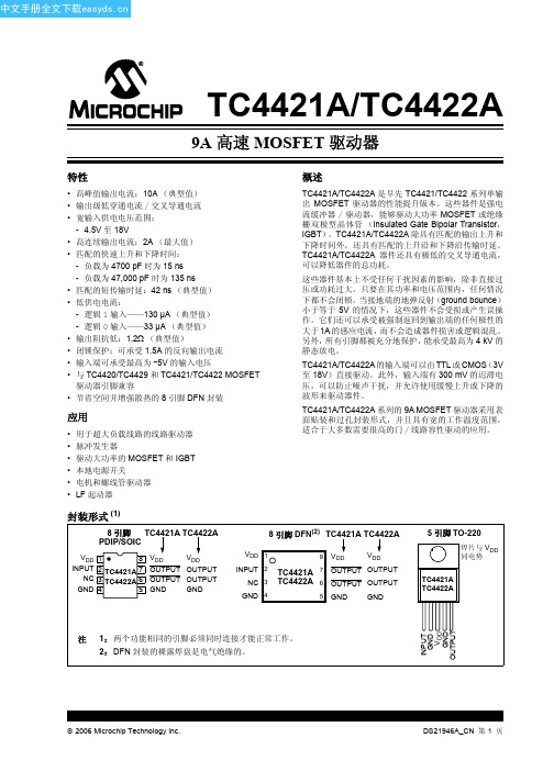
EI40中文资料(ferroxcube)中文数据手册「EasyDatasheet - 矽搜」
- 格式:pdf
- 大小:150.97 KB
- 文档页数:3


KA01064F/00/ZH/13.1171204947简明操作指南Prosonic M FMU40/41/42/43/44超声波物位仪本文档为《简明操作指南》;不得替代随箱包装中的《操作手册》。
详细信息请参考随箱CD 光盘中的《操作手册》和其他文档资料,或登录以下网址查询:/deviceviewer。
E+H中国服务供应商 深圳市百合顺电子科技有限公司 电话:0755-22721800 网站:www.ehbhs.comProsonic M FMU40/41/42/43/44 FOUNDATION Fieldbus目录1 安全指南 . . . . . . . . . . . . . . . . . .. . . . . . . . . . . . . . . . . . . . . . . . . . . . . .3 1.1 指定用途 . . . . . . . . . . . . . . . . . . . . . . . . . . . . . . . . . . . . . . . . . . . . . . . . . . . . . . . . . . . . . . . . . 3 1.2 安装、调试和操作 . . . . . . . . . . . . . . . . . . . . . . . . . . . . . . . . . . . . . . . . . . . . . . . . . . . . . . . . . .3 1.3 操作安全和过程安全 . . . . . . . . . . . . . . . . . . . . . . . . . . . . . . . . . . . . . . . . . . . . . . . . . . . . . . . . 3 1.4 返回 . . . . . . . . . . . . . . . . . . . . . . . . . . . . . . . . . . . . . . . . . . . . . . . . . . . . . . . . . . . . . . . . . . . . . 31.5 安全图标 . . . . . . . . . . . . . . . . . . . . . . . . . . . . . . . . . . . . . . . . . . . . . . . . . . . . . . . . . . . . . . . . . 42 安装 . . . . . . . . . . . . . . . . . . . . . .. . . . . . . . . . . . . . . . . . . . . . . . . . . . . .4 2.1 到货验收、储存 . . . . . . . . . . . . . . . . . . . . . . . . . . . . . . . . . . . . . . . . . . . . . . . . . . . . . . . . . . . . 4 2.2 安装 . . . . . . . . . . . . . . . . . . . . . . . . . . . . . . . . . . . . . . . . . . . . . . . . . . . . . . . . . . . . . . . . . . . . . 5 2.3 安装条件 . . . . . . . . . . . . . . . . . . . . . . . . . . . . . . . . . . . . . . . . . . . . . . . . . . . . . . . . . . . . . . . . . 7 2.4 测量范围 . . . . . . . . . . . . . . . . . . . . . . . . . . . . . . . . . . . . . . . . . . . . . . . . . . . . . . . . . . . . . . . . 10 2.5 安装提示(FMU40/41) . . . . . . . . . . . . . . . . . . . . . . . . . . . . . . . . . . . . . . . . . . . . . . . . . . . . . . 13 2.6 旋转外壳 . . . . . . . . . . . . . . . . . . . . . . . . . . . . . . . . . . . . . . . . . . . . . . . . . . . . . . . . . . . . . . . . 142.7 安装后检查 . . . . . . . . . . . . . . . . . . . . . . . . . . . . . . . . . . . . . . . . . . . . . . . . . . . . . . . . . . . . . . 143 接线 . . . . . . . . . . . . . . . . . . . . . .. . . . . . . . . . . . . . . . . . . . . . . . . . . . .15 3.1 在F12/F23外壳中接线 . . . . . . . . . . . . . . . . . . . . . . . . . . . . . . . . . . . . . . . . . . . . . . . . . . . . . 15 3.2 在T12外壳中接线 . . . . . . . . . . . . . . . . . . . . . . . . . . . . . . . . . . . . . . . . . . . . . . . . . . . . . . . . . 16 3.3 使用基金会现场总线(FF)插头接线 . . . . . . . . . . . . . . . . . . . . . . . . . . . . . . . . . . . . . . . . . . . 16 3.4 接线端子分配 . . . . . . . . . . . . . . . . . . . . . . . . . . . . . . . . . . . . . . . . . . . . . . . . . . . . . . . . . . . . . 17 3.5 基金会现场总线(FF)电缆规格. . . . . . . . . . . . . . . . . . . . . . . . . . . . . . . . . . . . . . . . . . . . . . . 17 3.6 供电电压 . . . . . . . . . . . . . . . . . . . . . . . . . . . . . . . . . . . . . . . . . . . . . . . . . . . . . . . . . . . . . . . . 18 3.7 推荐连接 . . . . . . . . . . . . . . . . . . . . . . . . . . . . . . . . . . . . . . . . . . . . . . . . . . . . . . . . . . . . . . . . 183.8 连接后检查 . . . . . . . . . . . . . . . . . . . . . . . . . . . . . . . . . . . . . . . . . . . . . . . . . . . . . . . . . . . . . . 194 操作 . . . . . . . . . . . . . . . . . . . . . .. . . . . . . . . . . . . . . . . . . . . . . . . . . . .20 4.1 操作方式 . . . . . . . . . . . . . . . . . . . . . . . . . . . . . . . . . . . . . . . . . . . . . . . . . . . . . . . . . . . . . . . . 20 4.2 操作菜单结构 . . . . . . . . . . . . . . . . . . . . . . . . . . . . . . . . . . . . . . . . . . . . . . . . . . . . . . . . . . . . . 204.3 显示与操作单元 . . . . . . . . . . . . . . . . . . . . . . . . . . . . . . . . . . . . . . . . . . . . . . . . . . . . . . . . . . . 215 调试 . . . . . . . . . . . . . . . . . . . . . .. . . . . . . . . . . . . . . . . . . . . . . . . . . . .24 5.1 功能检查 . . . . . . . . . . . . . . . . . . . . . . . . . . . . . . . . . . . . . . . . . . . . . . . . . . . . . . . . . . . . . . . . 24 5.2 开启测量设备 . . . . . . . . . . . . . . . . . . . . . . . . . . . . . . . . . . . . . . . . . . . . . . . . . . . . . . . . . . . . . 24 5.3 基本设置 . . . . . . . . . . . . . . . . . . . . . . . . . . . . . . . . . . . . . . . . . . . . . . . . . . . . . . . . . . . . . . . . . 25 2Prosonic M FMU40/41/42/43/44 FOUNDATION Fieldbus安全指南1安全指南1.1指定用途Prosonic M是一款一体式测量仪表,用于连续、非接触式物位测量。

NetEngine40E全业务路由器N etEngine40E系列全业务路由器(以下简称NE40E)是华为公司推出的高端网络产品,主要应用在IP骨干网、IP城域网以及其他各种大型IP网络的边缘位置,与NE5000E、NE80E核心路由器产品配合组网,形成结构完整、层次清晰的IP网络解决方案。
NE40E基于分布式的硬件转发和无阻塞交换技术,具有良好的线速转发性能,优异的扩展能力,完善的QoS机制和强大的业务处理能力。
NE40E基于最新的可扩展400G平台,实现40G/Slot到400G/Slot的平滑扩展,且兼容现网所有线卡,最大限度保护客户的投资。
NE40E具有强大的汇聚接入能力,凭借丰富的特性支持,可以灵活部署L2VPN,L3VPN,组播,组播VPN,MPLS TE,QoS等,实现业务运营级的可靠性承载;同时,NE40E全面支持IPv6,可以实现IPv4到IPv6的平滑过渡。
因此,NE40E可以灵活应用在IP/MPLS网络的边缘、核心,可以简化网络结构,提供丰富的业务类型和可靠的服务质量,是IP/MPLS 承载网向宽带化、安全化、业务化、智能化发展的重要源动力。
NE40E系列主要包括NE40E-X16、NE40E-X8、NE40E-X3和NE40E-8,适应不同规模的网络组网需求。
NE40E-X16 NE40E-X8 NE40E-X3 NE40E-8产品特点♦领先的400G平台NE40E系列节能减排机框基于400G平台,具备每槽位400Gbps转发能力,可以从每槽位40Gbps平滑扩容到400Gbps带宽,满足未来3~5年的带宽增长需求。
同时NE40E系列基于现有VRP软件平台,完全兼容现网所有线卡,充分利旧,最大限度保护客户的投资。
整机采用高端口密度、紧凑性设计,单机端口密度最大可达64×10G,单机柜容量最大可达132×10G,可以有效的节省空间。
♦绿色的设计理念节能减排整机采用完全绿色的设计,更加环保节能。


Impulse X4 系列便携式复合气体检测仪操作说明书!重要提示:!在首次使用仪器以前请认真阅读本手册,您将会掌握仪器正确的使用方法和了解仪器的功能,包括操作,维护,功能设置等内容。
!为了使操作者更安全,请按照手册中的要求,定期对仪器进行标定。
!如果在使用过程中,遇到的故障或问题在本手册中没有提到,请直接联系制造商Zellweger Analytics,或联系当地的代理商/服务商。
!警告和注意:·更换任何元器件都有可能损坏仪器的本质安全结构。
·如果需要使用存储卡,请选用Zellweger Analytics 提供的存储卡(订货号2566-0435),使用其它的存储卡有可能损坏仪器的本质安全结构。
·在允许的储存期之后激活检测器,有可能影响仪器的使用性能和保质期。
·应使用许可的5号干电池,如劲量电池,不要使用质量低下的干电池,以免影响仪器的本质安全性能。
·在更换电池时,应同时更换2节型号相同的新电池。
·在电池欠压提示后,应尽快更换新电池,以免旧电池漏液损坏仪器。
·在低温环境下,电池的寿命会缩短。
·更换电池时,应该在安全环境下进行。
·当更换任何一个传感器的情况下,都需要对仪器进行标定。
·在每天使用以前,应完成仪器的自检过程。
·定期的对仪器用标气进行测试,检查声、光、振动报警是否正常。
·标定时应选用厂家或国家认证合格企业提供的标准气体。
·标定时应在良好通风的环境下进行,以避免污染。
·不要在仪器电量不足的情况下标定。
·不要在富氧的环境下使用本仪器。
·可燃气体传感器的灵敏度会受到高浓度硫化物,卤素化合物,含硅化合物,以及含铅气体或蒸汽的影响,也叫“中毒”,应避免在以上的环境中使用仪器,如果必须使用,则使用完后应对仪器进行检测和标定,以免影响以后的使用。
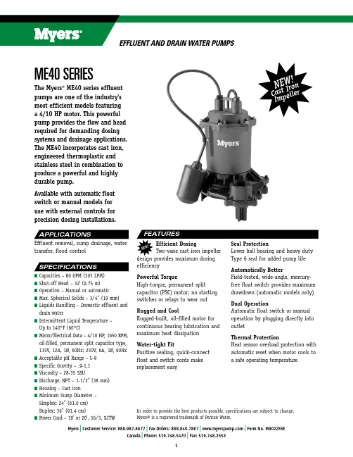
ME40 sEriEsIn order to provide the best products possible, specifications are subject to change.Myers® is a registered trademark of Pentair Water.Efficient Dosing Two-vane cast iron impeller design provides maximum dosing efficiencyPowerful TorqueHigh-torque, permanent splitcapacitor (PSC) motor; no starting switches or relays to wear out Rugged and CoolRugged-built, oil-filled motor for continuous bearing lubrication and maximum heat dissipation Water-tight FitPositive sealing, quick-connect float and switch cords make replacement easySeal ProtectionLower ball bearing and heavy duty Type 6 seal for added pump life Automatically BetterField-tested, wide-angle, mercury-free float switch provides maximum drawdown (automatic models only)Dual OperationAutomatic float switch or manual operation by plugging directly into outletThermal ProtectionHeat sensor overload protection with automatic reset when motor cools to a safe operating temperatureThe Myers ® ME40 series effluent pumps are one of the industry's most efficient models featuring a 4/10 HP motor. This powerful pump provides the flow and head required for demanding dosing systems and drainage applications. The ME40 incorporates cast iron, engineered thermoplastic and stainless steel in combination to produce a powerful and highly durable pump.Available with automatic float switch or manual models for use with external controls for precision dosing installations.Effluent removal, sump drainage, water transfer, flood controln C apacities – 80 GPM (303 LPM)n S hut-off Head – 32' (9.75 m)n O peration – Manual or automatic n M ax. Spherical Solids – 3/4" (19 mm)n L iquids Handling – Domestic effluent anddrain water n I ntermittent Liquid Temperature – Up to 140°F (60°C)n M otor/Electrical Data – 4/10 HP , 1650 RPM, oil-filled, permanent split capacitor type, 115V, 12A, 1Ø, 60Hz; 230V, 6A, 1Ø, 60Hz n A cceptable pH Range – 5-9n S pecific Gravity – .9-1.1n V iscosity – 28-35 SSU n D ischarge, NPT – 1-1/2" (38 mm)n H ousing – Cast iron n M inimum Sump Diameter – Simplex: 24" (61.0 cm) Duplex: 36" (91.4 cm)n P ower Cord – 10' or 20', 16/3, SJTWN E W ! C a s t I r o nI mp e l l e rCatalog Phase/ Discharge Switch Cord Approx. Wt.Number HP Volts Cycles Amps Size Type Length Lbs.ME40A-11 4/10 115 1/60 12.0 1-1/2" Tethered Automatic 10' 27 ME40AC-11 4/10 115 1/60 12.0 1-1/2" Tethered Automatic 20' 28 ME40M-11 4/10 115 1/60 12.0 1-1/2" Manual 10' 26 ME40MC-11 4/10 115 1/60 12.0 1-1/2" Manual 20' 27 ME40AC-21 4/10 230 1/60 6.0 1-1/2" Tethered Automatic 20' 28 ME40MC-21 4/10 230 1/60 6.0 1-1/2" Manual 20' 27 ME40P-1 4/10 115 1/60 6.0 1-1/2" Tethered Automatic* 10' 28 ME40PC-1 4/10 115 1/60 6.0 1-1/2" Tethered Automatic* 20' 29 ME40PC-2 4/10 230 1/60 6.0 1-1/2" Tethered Automatic* 20' 29*PiggybackEFFLUENT PUMPS – Pump(s) shall be F. E. Myers ME40 Series sump pumps selected in accordance with the following design criteria:Number of Pumps: _____________________Primary Design Flow: _____________________Primary Design Head: _____________________Minimum Shut-off Head: 32'Motor Horsepower: 4/10Motor Speed: 1650 RPMElectrical: 115 Volts, 1Ø, 60 Hz or230 Volts, 1Ø, 60 HzPUMP – The pump shall be designed to handle septic tank effluent and be capable of passing 3/4 inch spherical solids. The pump shall be capable of handling liquids with temperatures to 140°F intermittent.MOTOR – The pump motor shall be of the submersible type rated 4/10 hp at 1650 RPM and shall be for _____115 volts or _____230 volts single phase, 60 cycles. Single phase motor shall be of the shaded pole type with no relays or starting switches. Stator winding shall be of the open type with Class A insulation rated for 105°C maximum operating temperature. The winding housing shall be filled with clean dielectric oil to lubricate bearings and seals, and transfer heat from the windings to the outer shell. The motor winding assembly shall be pressed into the stator housing for best alignment and heat transfer.The motor shall be capable of operating over the full range of the performance curve without overloading the motor and causing any objectionable noise or vibration. The motor shall have two bearings to support the rotor; an upper sleeve bearing to accommodate radial loads and a lower sleeve bearing with thrust pad to take thrust and radial loads.A heat sensor thermostat and overload shall be attached to the top end of the motor windings and shall be wired in series with the windings to stop the motor if the motor winding temperature reaches 221°F. The overload thermostat shall reset automatically when the motor cools to a safe operating temperature.POWER CORD – The motor power cord shall be _____10 or _____20 feet SJOW or SJTW type. The power and switch cords shall be of the positive sealing, quick-disconnect type. The power and switch cable connections shall be sealed at the motor entrance by means of a compression nut which serves to make a positive electrical connection and prevent water from entering the cable jacket and motor housing.OPTIONAL CONTROL SWITCH – The effluent pump shall be controlled by an optional integral float switch. The float switch shall be of a non-mercury type and be capable of directly controlling the pump motor without the need for an external control panel.SHAFT SEAL – The motor shall be protected by a rotating mechanical shaft seal. The seals shall have carbon and ceramic seal faces lapped to a tolerance of one light band. Metal parts and springs for seals shall be stainless steel.PUMP IMPELLER – The pump impeller shall be of the two vane enclosed type. The impeller shall be constructed of cast iron.MOTOR CASTINGS – The motor housing castings shall be of high tensile strength Class 30 gray cast iron. Castings shall be treated with phosphate and painted with a high quality air dried modified epoxy resin for corrosion protection. PUMP CASE – The pump case shall be a high efficiency volute design capable of passing 3/4 inch spherical solids. The pump volute shall be constructed of corrosion resistant, high impact, engineered thermoplastic.FASTENERS – All exposed fasteners shall be of stainless steel.。
DIGITAL INDUCTANCE AND CAPACITANCE METERAX-LC401.SUMMARIZEThe meter is a stable multimeter with32/1LCD display,It uses the LCD with26mm high make the reading clearly.unit symbol displaying.The meter is used to measure inductance and capacitance.It takes dual-integral A/D convert as key ing large scale integrated circuit.It’s an ideal tool for lab,factory and family.2.SAFETY NOTEThe meter meets the standards of IEC1010.Read the operation manual carefully before operation.1.Do not input DC Voltage or AC Voltage.2.The voltage below36V is safety.To avoid electric shock,check whether the test leads are connected correctly,whether the insulation is good when measuring over36DCV or25ACV,.3.Remove the test leads when changing function and range.4.To select correct function and range,beware of error operation.;5.SAFETY SYMBOLS“”THE OPERATOR MUST REFER TO THE MANUAL,“”LOW BATTERY.3.CHARACTERISTIC3.1.GENERAL(1).Displaying:LCD displaying.(2).Max.displaying:1999(31/2digit)auto polarity indication.(3).Measuring method:dual slope A/D conversion.(4).Sampling rate:approx.3times/second.(5).Over range indication:the MSD displays“1”.(6).Low battery indication:“”appears.(7).Operation environment:(0~40)℃,R.H.<80%.(8).Power:9V×1(NEDA1604/6F22or equivalent model)-not included(9).Size:190×88.5×27.5mm(10).Weight:approx320g(include battery)(11).Accessory:operation manual,holster,gift box,test leads.3.2.TECHNICAL CHARACTERISTICAccuracy:±(a%×rdg+d)Temperature:(23±5)℃,R.H.<75%,one year guaranteed from the production date.(1).Inductance(L)1-RANGE2-ACCURACY3-RESOLUTION4-MEASURE FREQUENCY5-THROUGH CURRENTuH=10^-6H mH=10^-3H(2).Capacitance(C)1-RANGE2-ACCURACY3-RESOLUTION4-MEASURE FREQUENCY5-THROUGH VOLTAGEPF=10^-12F nF=10^-9F uF=10^-6F4.OPERATION4.1.Front panel description(1).LCD display:display the measured value and unit.(2).Backlight switch:turn on/off the backlight.(3).Function key:Selecting measuring range and function.(4).Input terminal:connect the test leads.(5).Measuring switch:Press the key to start measure.4.2.Consideration of measurement(1)This LC METER is intended for measuring the capacitance value of a capacitor,the inductance value of an inductor.It is not intended for determining the“Q”factor for above reactive components.Misleading readings may be obtained if the measurement of the inductance or capacitance of a resistor is attempted.(2)When measuring components in circuit,the circuit must be switched off and de-energized before con-necting the test leads.(3)For all measurements,should connect BLACK test lead to“-”terminal and RED test lead to“+”termi-nal.(4)Do not short-circuit the input terminal,or will cause the internal burning.4.3.Inductance(L)measurement procedure(1)Set POWER switch to“ON”position.(2)Select the range switch for the maximum expected inductance.(3)Connect the alligator clips to the inductor leads.(4)Read the display.The value is direct reading in the electrical units(uH,H)indicated at the selected switch.If DISPLAY show“1”.It indicates on Out-of-Range measurement.If the display indicates one of more reading zeros,shift to the next lower range scale to improve the resolution of the measurement. NOTE:(a)If the inductance value is unmarked,start from the2mH range and keep increasing until the over range indication goes off and a reading is obtained.(b)Very low inductance measurement should be performed by using extremely short leads in order to avoid introducing any stray inductance.(c)This instrument is not intended for determining the“Q”factor for the inductor.Misleading readings may be obtained if the measurement of the inductance of a resistor is attempted.(d)At range2Mh,short–circuit the test leads,to measure the inductance value,then substracts it from the real measurement.4.4.Capacitance(C)measuring procedure(1)Set POWER switch to“ON”position.(2)Select the range switch for the maximum expected capacitance.(3)Fully discharge any capacitors.(4)Connect the alligator clips to the capacitor leads.(5)Read the display.The value is direct reading in the electrical unit(nF,uF)indicated at the selected range switch.If DISPLAY show“1”,It indicate on Out-of-Range measurement.If the display indicates one or more leading zeros,shift to the next lower range scale to improve the resolution of the measurement. NOTE:(a)If the capacitance value is unmarked,start from the2nF range and keep increasing until the over-range indication goes off and a reading is obtained.(b)A shorted capacitor will read over-range on all ranges.A capacitance with low voltage leakage will read over range,or a much higher value than normal.An open capacitor will read zero on all ranges(possible a few pF on2nF range,due to stray capacitance of the instrument).(c)Very low capacitance measurement should be performed by using extremely short leads in order to avoid introducing any stray inductance.(d)When using the optioned test leads,remember that the leads introduce a measurable capacitance to the measurement.As a first approximation,the test capacitance did measured by opening the leads at the trips,recording the open circuit value and subtracting the value.(e)Capacitors,especially electrolytic,often have notoriously wide tolerances.Do not be surprised if the measured value is greater than the value marked on the capacitor,unless it is a close tolerance type. However,value is seldom drastically below the rated value.5.MAINTENANCEDO NOT try to verify the circuit for it’s a precision meter.1.Beware of waterproof,dustproof and shockproof.2.Do not operate and store the meter in the circumstance of hightemperature,high humidity,and flammability,explosive and strong magnetic field.e the damp cloth and soft solvent to clean the meter,do not use abrasive and alcohol.4.If do not operate it for a long time,should take out the battery.5.When LCD displays“”symbol,should replace thebattery as below:(a).Ensure the instrument is not connected to any external circuit.Set the selector switch to OFF position and remove the test leads from terminals.(b).Remove the screw on the bottom case and lift the bottom case.(c).Remove the spent battery and replace it with a battery of the same type.FUSE REPLACEMENTUse the same type fuse as specified.1.Remove the screw on the back of the case.2.Replace the fuse with a new one.3.Reinstall the screw in the case bottom.6.TROUBLE SHOOTINGIf the meter does not work properly,check the meter as following:CONDITIONS//////WAY TO SOLVENO DISPLAYING//////-Power is off;-Replace battery””symbol displays//////-Replace batteryNO CURRENT INPUT//////-Replace fuseBIG ERROR//////-Replace battery•The specifications are subject to change without notice.•The content of this manual is regarded as correct,error or omits Pls.contact with factory.•We hereby will not be responsible for the accident and damage caused by improper operation.•The function stated for this User Manual cannot be the reason of special usage.AX-LC40-Errata1.ErrataImportant!In the capacity measurement table,instead of the1000µF range there should be: 500µF,measurement accuracy:±(5.0%+5)Other capacity measurement data remain unchanged.。

769®for long travelapplicationsE4/4HD | P4 | rol e-chains®| autoglide770Precise separation -E4/4HD Wide, rounded plastic Closed and open styles Hinged snap-open4040HD5650 -600104 -65484 5050HD8050 -600110 -660108 R8840HD5675 -462129 -51684 R9850HD8075 -462135 -522108Request InfoRequest InfoThe maintenance-free series 4040 protects the igus chainflex motor and signal cables during the lifting and lowering movements of the tidal turbine and also protects them against agressive ambient conditions. The travel is to approx. 20 m in vertical direction above and below water4040HDcrossbars every link 8840HDfully enclosedRequest InfoHot Chips up to 850°Ce-tubes that repel hot chip up to 850ºC. Some applications, depending on amount and size of the chips, can burn or melt the surface. That is no longer the case with the igus igumid HT material.More information www.igus.eu/HTRequest InfoLockable full-width shelvesRequest InfoRequest Info779************|www.igus.eurol e-chain ®- rolling instead of glidingSpecial solution for long travel applications. Reduce push/pull forces by more than 75% (rolling)T ravels up to 800 m T ravel speeds up to 6 m/s for long travel applications and high speeds Various roller types for optimum application adaption More information from page 806P4 profile-rol e-chain ®- reduce energy consumption by 57%Safe, low noise, abrasion-resistant energy supply system on long travels up to 800 m and more High fill weights up to 30 kg/m High speeds up to 10 m/s Identical pitch of the e-chain link with or without roller Integrated captive roller in the side part autoglide crossbars for a safe guiding More information from page 7865050HDcrossbars every link 9850HDfully enclosede-chains ®| Series 5050HD | crossbars every link (removable along the inner and outer radius)fully enclosed (hinged lids, snap-open along the outer radius from one side)Request InfoHot Chips up to 850°Ce-tubes that repel hot chip up to 850ºC. Some applications, depending on amount and size of the chips, can burn or melt the surface. That is no longer the case with the igus igumid HT material.More information www.igus.eu/HTRequest InfoLockable full-width shelvesRequest Info45°Request Inforol e-chain ®- rolling instead of glidingSpecial solution for long travel applications. Reduce push/pull by more than 75%(rolling) T ravels up to 800 m T ravel speeds up to 6 m/s for long travel applications and high speeds Various roller types for optimum application adaption More information from page 806P4 profile-rol e-chain ®- reduce energy consumption by 57%Safe, low noise, abrasion-resistant energy supply system on long travels up to 800 m and more High fill weights up to 30 kg/m High speeds up to 10 m/s Identical pitch of the e-chain link with or without roller Integrated captive roller in the side part autoglide crossbars for a safe guiding More information from page 786iF product design award 2007 igus system P4+System P4Better cables, stronger , rolling e-chains ®Rolling instead of glidingStronger e-chains ®Optimised cablesGliding applicationStandard100%chainflex®-17%E4.1-17%rol e-chain®-37%System P4-57%Tribo-optimised plastic rollers for all igus P4 systems Wear optimised Long cycle life Extension link for heavy fill weights 2 inner heights available (56, 80 mm)50% higher fill weight possible Aluminium guide trough systemSpecial geometry in combination with autoglide cross bars allows for offset Offset operation of upper and lower run,resulting in continuous roll-through surfaceRequest Infoprofile-rol e-chain®with comb style autoglide crossbars, medium inner height P4.32 crossbars every linkP4.32| Crossbars every link - removable along the inner and outer radiusRequest Inforresulting in continuous roll-through surface1-800-453-1692Request InfoLockable full-width shelvesRequest Infoprofile-rol e-chain®with comb style autoglide crossbars, medium inner height P4.42 crossbars every linkP4.42 | Crossbars every link - removable along the inner and outer radiusRequest Inforresulting in continuous roll-through surface1-800-453-1692Request InfoLockable full-width shelvesRequest Info56Extension link for heavy fill weights50% higher fill weight possible Maximum rigidityDivides cross section into compartments (electric/hydraulic) 2 inner heights (56, 80 mm) Available upon request. More information www.igus.eu/P4profile-rol e-chain ®with comb style autoglide crossbars, large inner heightP4.56 | Crossbars every link - removable along the inner and outer radiusP4.56 crossbars every linkRequest Inforresulting in continuous roll-through surface1-800-453-1692Request InfoLockable full-width shelvesRequest Infoprofile-rol e-chain®with comb style autoglide crossbars, large inner height P4.80 crossbars every linkP4.80 | Crossbars every link - removable along the inner and outer radiusRequest InfoExtension link for heavy fill weights50% higher fill weight possible Maximum rigidityDivides cross section into compartments (electric/hydraulic)2 inner heights (56, 80 mm) Available upon request.More information www.igus.eu/P4rresulting in continuous roll-through surface1-800-453-1692Request InfoLockable full-width shelvesRequest Info®®rol ●Shifting systems2828R3250- 40074- 42454 3838R4250- 40077- 42764 7728R3250- 30074- 32454 7838R4250- 30077- 327644040RHD5650- 600104- 65484 5050RHD8050- 600110- 660108 8840RHD5657- 125129- 51684 9850RHD8073- 141135- 522108Request InfoPhone +49 2203 9649-800P4 profile-rol e-chain®- reduce energy consumption by 57% Safe, low noise, abrasion-resistant energy supply system on long travels up to 800 m and more High fill weights up to 30 kg/m High speeds up to 10 m/s Identical pitch of the e-chain link with or without roller Integrated captive roller in the side part autoglide crossbars for a safe guidingMore information from page786Shipyard-Crane: 180 m travel, 30 kg/m fill weight. No faults with the igus rol-echain since installation in 2001igus rol e-chain saves drive power on long travels. Safelyguided in the igus guide troughs2828Rcrossbars every link7728Rfully enclosed Request InfoOptimised, cable-friendly Pivoting KMA mounting Aluminium SuperT rough,basic versionRequest Info3838Rcrossbars every link7838Rfully enclosed Request InfoOptimised, cable-friendly interior separation Pivoting KMA mounting Aluminium SuperT rough,basic versionRequest Info4040Rcrossbars every link8840Rfully enclosed Request InfoOptimised, cable-friendly Pivoting KMA mounting Aluminium SuperT rough,basic versionRequest Info4040RHDcrossbars every link8840RHD fully enclosedRequest InfoOptimised, cable-friendly interior separation Steel mounting brackets,pivoting, robust andRequest Info5050Rcrossbars every link9850Rfully enclosed Request Info。

Approved for Class I and Class II applications, the ECM range of single and multiple output AC-DC, 40-60 W power supplies from XP feature the world's smallest footprint for units of these ratings. Both are just 2" x 4" (50.8 mm x 101.6mm) and 1.2" (30.48 mm) high. Furthermore, these high-density power supplies meet EN55022 Level Bconducted emissions with maximum leakage currents of 100 µA at 115 VAC or 200 µA at 230 VAC. As a result, these switchers areequally suitable for industrial, IT and medical applications, with no price premium for meeting medical requirements.The ECM40-60 series have single output versions from 5 V to 48 VDC, adjustable by ±10%, and dual and triple output versions covering combinations of 3.3 V , 5 V , 12 V , 15 V and 24 V . They are dual-fused for compliance with IEC60601-1 and efficiency is 80-85%, depending upon the model, so minimal excess heat is generated.The power supplies deliver full power between 0 °C and +50 °C and will operate at up to +70 °C with derating and only 5CFM of cooling. Comprehensive overvoltage, overload and short circuit protection is built in. Covers, looms and connector kits are available.ECM40-60Introduction•40 & 60 Watt Models •Small Size 2.0” x 4.0” x 1.2”•Low Leakage Current•Industrial & Medical Approvals•Full Load Available Convection Cooled •Wide Operating Temperature 0 °C to +70 °C •Level B Conducted Emissions •EN61000-3-2 Compliant •Universal AC Input 90-264 VAC •Input Frequency 47-63 & 440 Hz •Single & Multiple Outputs •Cover Kits Available•Mating Connector & Loom Kits AvailableInput CharacteristicsAll specifications are at nominal input, full resistance load at 25°C unless otherwise stated. Output CharacteristicsGeneral SpecificationsEnvironmentalElectromagnetic Compatibility & ImmunitySafety Approvals2.To receive unit with cover fitted, add suffix ‘-C’ to model number. For Class I operation only.3. A 120% peak load can be taken for up to 100 ms with a 25% duty cycle. Average load not to exceed maximum power rating.†Available from Farnell InOne. *Available from Newark InOne.Transient ResponseAll ECM60 models convection-cooled All ECM60 models with 5 CFMECM60US24 25% load changeEfficiency Versus Input VoltageECM60US24 with 60 W load ECM60UT33 with 50 W load Efficiency Versus Output LoadECM60US24 at 230 VAC input ECM60UT33 at 230 VAC inputStart Up DelayECM60US24 with 60 W loadECM60US24 with 60 W load at 230 VACECM60UT33 with 60 W loadHold Up TmeOverload CharacteristicsECM60US24. When current reaches 5.4 A, outputgoes into trip and restart (hiccup) modeRipple & NoiseECM60US24 with 60 W load Noise measured is 64 mV pk-pk ECM60UT33 output 1 with 30 W load. Noise measured is 36 mV pk-pkECM60UT33 output 2 with 15 W load. Noise measured is 68 mV pk-pk ECM60UT33 output 3 with 7 W load. Noise measured is 34 mV pk-pkConducted NoiseECM60US24 at full loadECM60UT33 at full loadMechanical Details - Single Output ModelsThermal Considerationsø0.312 (7.92) clearance top and bottomWeight: approx. 0.33 lb (150g)Notes1. All dimensions in inches (mm). Tolerance .xx = ±0.02 (0.50); .xxx = ±0.01 (0.25)2. Cable harnesses with 300mm wire available.For single output models, order part number ECM40/60S LOOM. For multi-output models, order part number ECM40/60DT LOOM .3. Mating connector kit available. Order part number ECM40/60 CONKIT.4. Covers available. Order part number ECM40/60 COVER. Cover dimensions are 4.49 x 2.52 x 1.52 (114 x 64 x 38.5)5. †All accessories available from Farnell InOne.J1 mates with Molex housing 43061-0003and Molex series 5194 crimp terminals.Optional ground (0.25 faston) tab available.To ensure correct and reliable operation of the PSU, the temperature of the components listed in the table below must not be exceeded. See mechanical details for component locations.J2 mates with Molex housing 43061-0006 &Molex series 5194 crimp terminals.Mechanical Details - Single Output Models (3 x 5)Thermal ConsiderationsNotes1. All dimensions in inches (mm). Tolerance .xx = ±0.02 (0.50); .xxx = ±0.01 (0.25)2. Cable harnesses with 300mm wire available.For single output models, order part number ECM40/60S LOOM. For multi-output models, order part number ECM40/60DT LOOM .3. Mating connector kit available. Order part number ECM40/60 CONKIT.4. Covers available. Order part number ECM40/60 COVER. Cover dimensions are 4.49 x 2.52 x 1.52 (114 x 64 x 38.5)5. †All accessories available from Farnell InOne.J1 mates with Molex housing 43061-0003and Molex series 5194 crimp terminals.Optional ground (0.25 faston) tab available.To ensure correct and reliable operation of the PSU, the temperature of the components listed in the table below must not be exceeded. See mechanical details for component locations.J2 mates with Molex housing 43061-0006 &Molex series 5194 crimp terminals.0.14 (3SMD Component HeiMechanical Details - Multi Output ModelsThermal Considerationsø0.312 (7.92) clearance top and bottomWeight: approx. 0.33 lb (150g)Notes1. All dimensions in inches (mm). Tolerance .xx = ±0.02 (0.50); .xxx = ±0.01 (0.25)2. Cable harnesses with 300mm wire available.For single output models, order part number ECM40/60S LOOM. For multi-output models, order part number ECM40/60DT LOOM .3. Mating connector kit available. Order part number ECM40/60 CONKIT.4. Covers available. Order part number ECM40/60 COVER. Cover dimensions are 4.49 x 2.52 x 1.52 (114 x 64 x 38.5)5. †All accessories available from Farnell InOne.J1 mates with Molex housing 43061-0003and Molex series 5194 crimp terminals.Optional ground (0.25 faston) tab available.To ensure correct and reliable operation of the PSU, the temperature of the components listed in the table below must not be exceeded. See mechanical details for component locations.J2 mates with Molex housing 43061-0006 &Molex series 5194 crimp terminals.North American Sales OfficesXP Power401 Commonwealth Drive Haw Par Technocentre Singapore 149598Phone : +65 64116900F ax : +65 6741 8730Email :*******************Asian HQEuropean Sales OfficesDistributorsAustralia .....+61 2 9809 5022 Amtex Austria . . . . . .+43 (0)2282 3144Vitecom Czech Rep. .+420 235 366 129 Vums Powerprag Czech Rep. .+420 377 824 986 Vienna Trading Finland ...+358 (0)9 2906 1990 Cool Power Israel . . . . . . . .+97 2 9 749 8777 AppletecJapan . . . . . . . .+8148 864 7733BellnixKorea . . . . . . . .+8231 421 1404Bellkor Portugal ......+3493 263 33 54 Venco Russia . . . . . . .+7 (495)234 0636 Prosoft South Africa ...+2711 4531910 Vepac Spain . . . . . . . .+34 93 263 33 54VencoXP PowerEuropean HQHorseshoe Park PangbourneBerkshire, RG8 7JWPhone : +44 (0)118 984 5515F ax : +44 (0)118 984 3423Email :*******************XP PowerNorth American HQ990 Benecia Avenue Sunnyvale, CA 94085Phone : +1 (408) 732-7777F ax : +1(408) 732-2002Email :*******************Toll Free . . . . . . . . . . . . . . . . . . +1 (800) 253-0490Central Region .............+1(972) 578-1530Eastern Region ............+1 (973)658-8001Western Region . . . . . . . . . . . . +1 (408) 732-7777Belgium .................+33 (0)1 45 12 31 15Denmark ....................+45 43 4238 33France . . . . . . . . . . . . . . . . . .+33 (0)145 12 31 15Germany .................+49(0)421 63 93 3 0Italy . . . . . . . . . . . . . . . . . . . . . . .+39039 2876027Global Catalogue DistributorsAmericas .............Newark Europe & Asia . . . . . . . . . .Farnell Netherlands ..............+49 (0)421 63 93 3 0Norway . . . . . . . . . . . . . . . . . . . . .+47 63 94 60 18Sweden .................+46 (0)8 555 367 00Switzerland ...............+41(0)56 448 9080United Kingdom ...........+44 (0)118 984 5515。

i40There isn’t simply one thing that sets the i40 apart from other vehicles on the market.It’s a blend of comfort, technology and performan-ce-related innovations that combine to create a unique driving experience.The bolder front grill with chrome treatment and sleeker exterior body heighten your confidence.Powertrain enhancements elevate fuel efficiency andoverall performance to make driving a pure pleasure.next level.i40 is the perfect expression of your individuality and preference for finding your own road.The stylish 18˝alloy wheels will turn heads as will the new bumper with its futuristic aero-curtaintreatment and the LED rear lamps.Integrated memory system (IMS)7″ LCD Audio system Supervision clusterSteering wheel remote controlsThe improved i40 surrounds you and your passenger with comfort.The premium audio system provides exceptional sound in the cabin spacewith intuitive, and direct interface. Added storage space in the rear armrestholds a variety of items. And don’t forget the stylish door scuffs.A further upgrade forstylish adventure.i40’s surfaces are finished in a sophisticated color scheme characterized by muted, carefullymatched shades, while key touch points have subtle textures that stimulate your senses.A variety of seat options and functions comfortably hug your body just like the i40 hugs the road.Intuition, innovation, inspiration all come together in the i40.Glove box cooling Electric parking brake (EPB)Front seat ventilation systemSeat folding system (Flat type)Seat folding system (6:4 type)Sedan luggage capacityWagon luggage capacity When it comes to space, the i40 is unrivaled in its class with its spacious and versatile luggage space.With the release of a simple lever, backrests easily fold into the floor to create an extended luggage space. Whether you want to head for the outback with your mountain bike or haul a heavy load of luggage, i40 has got you covered.Spacious enough tofit all your desires.Advanced Traction Cornering Control This active cornering feature, utilizing capabilities from the Electronic stability control (ESC), allows i40 to improve cornering dynamics during more enthusiastic driving.A little can go a long way.i40’s perfectly tuned engines and transmissions are designed to take you furtherthan ever before between fill-ups. The 7-speed DCT automatic transmissionand variable valve timing are just a few of the numerous technical innovationsthat help squeeze more energy out of every drop of fuel and put the power rightwhere it should be, under your right foot.141ps /4,000rpm34.7kg.m /1,750~2,500rpmUII 1.7Diesel engine(DOHC)2.0 GDi Gasoline engine(DOHC with DCVVT)164(165)ps /6,200rpm20.7(20.8)kg.m/4,700rpm7-speed dual-clutch transmission (DCT)6-speed automatic transmissionPaddle shifters (Standard with automatic transmission)( ) SedanAdaptive Front-Lighting System (AFS)Low Beam Assist_Static (LBA-S)You never know what to expect when driving: obstacles and adverse situations can take you by surprise. Not to worry, i40 expects theunexpected with safety features designed to keep you out of danger.So sit back relax and enjoy the mind bending curves.Sudden surprises and obstacles, now obsolete.FeaturesLED high-mounted stop lampLight control system5″ 4.0B Audio systemWiper de-icerHID headlamps Chrome finish radiator grillMatt finish radiator grillAuto cruise controlFull auto air conditioning systemFront & rear seats warmer Child anchorsBluetooth hands-free systemDrive mode systemConnectivity (AUX, USB)C16˝ steel wheels17˝ alloy wheel16˝ alloy wheel18˝ alloy wheelManual air conditioning systemOutside mirror repeaters*Wheel tread : 16″ (front and rear) - 1,591 / 1,597 l 17″ (front and rear) - 1,579 / 1,585DimensionsOverall width1,815Wheel tread *1,579Wheel tread *1,5854,745Overall length 2,770Wheel base Overall height1,470Unit : mm● The above values are results from internal testing and are subject to change after validation.● Some of the equipment illustrated or described in this catalog may not be supplied as standard equipment and may be available at extra cost.● Hyundai Motor Company reserves the right to change specifications and equipment without prior notice. ● The color plates shown may vary slightly from the actual colors due to the limitations of the printing process.● Please consult your dealer for full information and availability on colors and trims.SpecificationsOverall width1,815Wheel tread *1,579Wheel tread *1,5854,775Overall length 2,770Wheel base Overall height1,470Typoon silver (T2X)Magnetic force (M2F)Earthy bronze (Y2B)Magnetic force (M2F)White cream (WW2)Stormy sea (ST2)Phantom black (NKA)Lava orange (YR2)Horizon red (RD2)White cream (WW2)Lava orange (YR2)Rain forest (R2F)Wild explorer (W2P)Exterior colorsBeige leatherInterior colorsBlack clothBlack leatherSpecial color packMerlot leather + Gray pattern pipingGray combi leather + Lava orange pipingYou can tailor the i40 driving experience to a style that is uniquely yours. Choose from a wide array of exterior/interior color combinations and optional equipment packages that meet your personal requirements and make i40 a true reflection of you. Versatile, smart and spacious: the i40 is the go-to vehicle for all your travel needs – and the ideal partnerfor an exciting, active life.Dealer stampHyundai Motor CompanyGEN. LHD 1806 ENG. WDCopyright © 2018 Hyundai Motor Company. All Rights Reserved.。
Technical Data FLIR E40Part number:49001-2201Copyright©2012,FLIR Systems,Inc.All rights reserved s and marks appearing herein are either registered trademarks or trademarks of FLIR Systems and/or its subsidiaries.All other trademarks,trade names or company names referenced herein are used for identification only and are the property of their respective owners.February 14,2012,07:12AM Corporate Headquarters FLIR Systems,Inc.27700SW Parkway Ave.Wilsonville,OR 97070USATelephone:+1-503-498-3547Website Customer support Imaging and optical data Legal disclaimerIR resolution160×120pixelsSpecifications subject to change without further notice.Camera models and accessories subject to regional Thermal sensitivity/NETD<0.07°C @+30°C (+86°F)/70mK market considerations.License procedures may apply.Field of view (FOV)/Minimum focus distance 25°×19°/0.4m (1.31ft.)Information and equipment described herein may require US Government authorization for exportSpatial resolution (IFOV) 2.72mrad purposes.Diversion contrary to US law is prohibited.Image frequency 60Hz Focus ManualZoom1–2×continuous,digital zoom,including panning Focal Plane Array (FPA)/Spectral range Uncooled microbolometer /7.5–13µmImage presentation Display Touch screen,3.5in.LCD,320×240pixelsImage modes IR image,visual image,picture in picture,thumbnail gallery Picture in Picture IR area on visual image MeasurementObject temperature range –20°C to +120°C (–4°F to +248°F)0°C to +650°C (+32°F to +1202°F)Accuracy±2°C (±3.6°F)or ±2%of reading,for ambient temperature 10°C to 35°C (+50°F to 95°F)Measurement analysis Spotmeter 3Area3boxes with max./min./averageAutomatic hot/cold detection Auto hot or cold spotmeter markers within area IsothermDetect high/low temperature/intervalDifference temperature Delta temperature between measurement functions or refer-ence temperatureEmissivity correctionVariable from 0.01to 1.0or selected from materials list External optics/windows correction Automatic,based on inputs of optics/window transmission and temperatureMeasurement correctionsReflected temperature,optics transmission and atmospher-ic transmissionSet-up Color palettes Arctic,Gray,Iron,Lava,Rainbow and Rainbow HC Set-up commandsLocal adaptation of units,language,date and time formats Languages21m l ,v e r .1.07Storage of images P/N:49001-2201Image storage Standard JPEG,including measurement data,on memory ©2012,FLIR Systems,Inc.cardAll rights reserved worldwide.Image storage modeIR/visual images;simultaneous storage of IR and visual imagesImage annotations TextText from predefined list or soft keyboard on touch screen Report generation•Separate PC software with extensive report generationVideo recording in camera Non-radiometric IR-video recording MPEG-4to memory cardVideo streamingRadiometric IR-video streaming Full dynamic to PC using USBNon-radiometric IR-video streaming Uncompressed colorized video using USB Digital camera Built-in digital camera 3.1Mpixel (2048×1536pixels),and one LED light Built-in digital lens data FOV 53°×41°Laser pointer LaserActivated by dedicated buttonLaser alignmentPosition is automatic displayed on the IR image Data communication interfaces Interfaces USB-mini,USB-A,composite video USB•USB-A:Connect external USB device•USB Mini-B:Data transfer to and from PC /Uncom-pressed colorized video Video out CompositePower system BatteryLi Ion,4hours operating timeCharging system In camera (AC adapter or 12V from a vehicle)or 2-bay chargerCharging temperature 0°C to +45°C (+32°F to +113°F)Power management Automatic shutdown and sleep mode (user selectable)Environmental data Operating temperature range –15°C to +50°C (+5°F to +122°F)Storage temperature range –40°C to +70°C (–40°F to +158°F)Humidity (operating and storage)IEC 60068-2-30/24h 95%relative humidity +25°C to +40°C (+77°F to +104°F)/2cycles EMC•EN 61000-6-2(Immunity)•EN 61000-6-3(Emission)•FCC 47CFR Part 15B (Emission)Encapsulation IP 54(IEC 60529)Bump 25g (IEC 60068-2-29)Vibration 2g (IEC 60068-2-6)SafetyPower supply:CE/PSE/EN/UL/CSA 60950-1Physical dataCamera weight,incl.battery 0.825kg (1.82lb.)Camera size (L ×W ×H)246×97×184mm (9.7×3.8×7.2in.)Tripod mountingUNC ¼"-20(adapter needed)m l ,v e r .1.07Scope of delivery P/N:49001-2201•Hard transport case©2012,FLIR Systems,Inc.•Infrared camera with lens All rights reserved worldwide.•Battery•Calibration certificate •Camera lens cap •Downloads brochure•FLIR Tools software CD-ROM •Handstrap •Memory card•Power supply,incl.multi-plugs •Printed Getting Started Guide•Printed Important Information Guide •Service &training brochure •USB cable•User documentation CD-ROM •Video cable•Warranty extension cardm l ,v e r .1.07All rights reserved worldwide.All rights reserved worldwide.All rights reserved worldwide.All rights reserved worldwide.All rights reserved worldwide.。

Elexant 4020i Installation InstructionsDESCRIPTIONThe nVent RAYCHEM Elexant 4020i is a compact, full-featured, touch-screen based, single point heat-tracing control module. It provides control and monitoring of Electric Heat Tracing (EHT) circuits for both freeze protection and process temperature maintenance. This controller can monitor and alarm on high and low temperature, high and low current, ground-fault levels, voltage, and supports a host of additional features to offer the utmost in control and monitoring of EHT.be installed correctly to ensure proper operation and to prevent shock or fire.ItemQtyDescriptionA 1Elexant 4020i moduleAPPROVALSHazardous LocationsClass I, Division 2, Group A,B,C,D T4 Type 4XClass I, Zone 2, AEx nA nC [ia Ga] IIC T4 Gc Ex ec nC [ia Ga] IIC T4 Gc DEMKO 18 ATEX2091 X IECEx UL 18 .0098X II 3 (1)G Ex ec nC [ia Ga] IIC T4 GcAssociated Apparatus Entity ParametersE4905419Proc. Cont. Eq.Use in Haz. Loc.(Associated Apparatus)Um = 305VAC Uo = 5.4V Ca = 65uF Io = 0.083ALa = 2mHKIT CONTENTSTOOLS REQUIRED • 3 mm head flat bladescrewdriver for IO terminal• 5 mm head flat bladescrewdriver for power terminalsGENERALModule Supply voltage100Vac to 277Vac, +/-10%, 50-60HzInternal power consumption< 24WElectromagnetic Compatibility IEC 61326-1:2012 / EN 61326-1:2013ENVIRONMENTALMaterials Fiber-Reinforced Plastic (FRP) or stainless steel (SS304)Ambient operating temperature-40°C to 70°C (-40°F to 158°F)Ambient storage temperature-55°C to 85°C (-67°F to 185°F)Relative humidity0% to 90%, noncondensingEnvironment PD2, CAT IIIMax altitude2,000 m (6,562 ft)CONTROL & LOADLoad Voltage, maximum690Vac, 50/60HzLoad Current, maximum63A continuous (limited by the rating of the output device)TEMPERATURE SENSOR INPUTSQuantity Three temperature inputs each of which can be individually set to one of the typesbelow.Types100Ω platinum RTD3-wire, α=0.00385 ohms/ohm/°CCan be extended with a 3-conductor shielded cable of 20Ω maximum perconductor100Ω nickel iron RTD2-wire, α=0.00599 ohms/ohm/°CCan be extended with a 2-conductor shielded cable of 20Ω maximum perconductor100Ω nickel RTD2-wire, α=0.00618 ohms/ohm/°CCan be extended with a 2-conductor shielded cable of 20Ω maximum perconductorThermocouple Requires external 4-20mA converter4-20mA current loop, ±0.05mA, 24Vdc loop power provided in device, external looppower can also be usedOptional - Limiter Versions OnlySafety Limiter One dedicated temperature input for the safety limiter100Ω platinum RTD3-wire, α=0.00385 ohms/ohm/°CRefer to H60624 - 40X0i Operator Manual for directions on installing, operating, and maintaining the Safety Limiter. Intrinsic Safety Barriers included on RTD Inputs when using IS models.RTD Intrinsic Safety Associated Apparatus Entity ParametersUo (Maximum Output Voltage): 5.4V La (Maximum External Inductance): 2mHIo (Maximum Output Current): 0.083A Ca (Maximum External Capacitance): 65uFPo (Maximum Output Power): 0.449WDIGITAL INPUTSQuantity Two multi-purpose inputs for connection to external dry (voltage free) contact or DCvoltageRating100 Ω max loop resistance or 5-24Vdc @ 1mA maximumOUTPUTSControl Relay Form-A wet contact:100Vac to 277Vac, 3A, 50/60HzDC (SSR) Control Output12Vdc @ 215 mA max.Analog (Linear Phase Control)0-10Vdc @ 215 mA max.Alarm Relay Form-C dry contact: 100Vac to 277Vac, 3A, 50/60Hz Auxiliary Output24Vdc, max load of 250mA @ 40°C, de-rated to 165mA @ 60°CCONNECTION TERMINALSPower Supply Input Screw terminals, 24 – 5 AWG (0.2 – 16.8mm2)Heating Cable Output Screw terminals, 24 – 5 AWG (0.2 – 16.8mm2)Torque Range for Screw Terminals1.2 – 1.5 NmGround (Earth)Three box lugs, 14 – 2 AWG (2.0 – 33.6 mm2)Sensor / Other Terminals Cage clamp terminals, 28 – 12 AWG (0.08 – 3.3 mm2)Minimum Conductor Temp. Rating80°CMOUNTINGElexant 4020i control modules are packaged in DIN rail mount housings for installation onto symmetric 35mm DIN rails, and in enclosures suitable for the intended environment.CONNECTIONS AND INDICATORSTerminals Function 1 TS1 (White)TS1 (Red)TS1 (Red)TS2 (White)TS2 (Red)TS2 (Red)TS3 (White)TS3 (Red)TS3 (Red)TS Lim (White)TS Lim (Red)TS Lim (Red)2 3 4 5678 9 10 1112Terminals Function 1 TC3+TC2+TC1+TC3–TC2–TC1–– No Connect SSR–SSR+DIGITAL INPUT (COM)DIGITAL INPUT 1DIGITAL INPUT 22 34 5678 9 10 1112 RS485 IN+RS485 IN–RS485 COM RS485 OUT+RS485 OUT–13 14 15 16 17 RS485 COM18E. Status LEDsF. USB ConnectorG. Ethernet ConnectionH. Profibus (optional)Status: Indicates status of Elexant 4020i module Off No powerGreen Normal operation, no internal faultsRed Device ResetFlash R/G Unlocked/CalibratedCOMMFlash Green Receive Active Alarm RedIlluminates when an alarm is trippedFlash Red Transmit ActiveOutput Shows status of switched outputC. TB3 WiringTerminals Function 24V COMExternal Jumper Required External Jumper Required56D. TB4 WiringWARNING: Shock Hazard.Disconnect from live voltage priorto accessing terminals1 Phase VersionFrontFrontTop Top Bottom Bottom SideSide3 Phase VersionThe Elexant 4020i module mounts onto a DIN 35 rail.MOUNTING: Insert the rear top of the module into the DIN rail, then push down and inwards to engage the clip.REMOVAL: Push the moduledownwards to disengage the clip, then rotate the module toward you.MOUNTING THE ELEXANT 4020i13RS485 COM18 1533912B1811TB1TB2TB3TB4F E HACDG12312345453. RS-485 IN131415141513An Ethernet connection is made via the RJ45 connector using a CAT 5E cable terminated with an RJ45 connector5. ETHERNETTB2161718161718The USB connector on the front of the unit can be used to import and export User setting configurations for ease of programming units and uploading of new firmware.7. USB CONNECTOR8. 3-WIRE RTD CONNECTIONS123456789101112123456789101112Terminate cable shields on panel mounted field terminals.1 2 34 5 61 2 345678912345678912345611. LOAD CONNECTIONS CONTACTOR - SINGLE PHASE/THREE PHASETo LoadN or L2Circuit BreakerContactor Output Relay(Module L1 Power)TB331PHElexant 4020i Three PhaseLoad Power InputTo WARNING: Shock Hazard. Disconnect from live voltage prior to accessing terminalsWARNING: Maximum wire OD is 8.70mm. Refer to local Electrial Standards for information on proper wire size.12. LOAD CONNECTIONS TO SSR - SINGLE PHASE/THREE PHASEBreaker1PHTB2893PHTB2Circuit Breaker89Load PowerTB2Circuit Breaker89block details.14. DIGITAL INPUTS789101112789101112The optional Limiter contactor is placed in line with the load. When the limiter has tripped, the relay will interrupt the power to the load.Refer to the CONNECTIONS section on page 3 for terminal block details.16. LIMITER RELAY CONNECTIONSL1L1N or L2External Limiter ContactorLoad PowerLimiter Relay(Module L1 Power)L2/N ..To Load2CTB3L2/N from Module Control Power1 421 42Class I, Division 2, Group A,B,C,D Class I, Zone 2, Group IIC IEC EX/ATEX Zone 2Class I, Div 1, Group A, B, C, D Class I, Zone 1, Group IIC Class I, Zone 0, Group IIC IEC EX/ATEX Zone 1, Zone 0123789456101112RTD123789456101112Specific Conditions of UseThis associated apparatus is intended for connection only to simple apparatus as defined in:• Article 504.2 and installed and temperature classified in accordance with Article 504.10(D) of the National Electrical Code (ANSI/NFPA 70)• Clause 3.5.5 and installed and temperature classified in accordance with Clause 16.4 of IEC 60079-14• Section F3 in Appendix F and installed and temperature classified in accordance with Section F4.2 in Appendix F of the Canadian Electrical Code, Part 1 (C22.1)• Or other local codes, as applicable.When connecting to simple apparatus, the cable length shall not exceed 3000m (9842ft).Associated apparatus must be installed in an enclosure suitable for the application in accordance with the National Electrical Code (ANSI/NFPA 70) for installation in the United States, the Canadian Electrical Code for installations in Canada, or other local codes, as applicable.The associated apparatus must be connected to a suitable ground electrode per the National Electrical Code (ANSI/ NFPA 70), the Canadian Electrical Code or other local installation codes, as applicable. The resistance of the ground path must be less than 1 ohm.Where multiple circuits extend from the same piece of associated apparatus, they must be installed in separate cables or in one cable having suitable insulation. Refer to Article 504.30(B) of the National Electrical Code (ANSI/NFPA 70) and Instrument Society of America Recommended Practice ISA RP12.06 for installing intrinsically safe equipment. Intrinsically safe circuits must be wired and separated in accordance with:• Article 504.20 of the National Electrical Code (ANSI/NFPA 70)• Clause 16.2 of IEC 60079-14• Section F4.2 in Appendix F of the Canadian Electrical Code, Part 1 (C22.1)• or other local codes, as applicable.This associated apparatus has not been evaluated for use in combination with another associated apparatus.Control equipment must not use or generate more than 305 V rms (Um) or dc with respect to earth.• The enclosure of the device shall be fitted with a locking mechanism such that it is only accessible with theuse of a tool.• Provisions shall be made, external to the appratus, to provide the transient protection device to be set at a level not exceeding 140% of the rated voltage at the input terminals of this apparatus.• To maintain an internal pollution degree 2 environment, after opening the enclosure, make sure there is no visible condensation or dust. Power the device and let it heat up for 5 minutes before closing the enclosure door.• Only install in areas with low risk of mechanical impact.• This equipment must be mounted in an ATEX/IECEx certified Zone 2 enclosure that provides a minimum ingress protection of IP 54 when used in a Zone 2 environment. The enclosure shall only be accessible with the use of a tool.The Elexant 4020i contains no user serviceable parts. Contact your nVent representative for service and a Return Authorization number if required.North AmericanVent899 Broadway Redwood City, CA 94063 United StatesTel +1.800.545.6258 Fax +1.800.527.5703**********************Europe, Middle East, Africa nVentRomeinse straat 14 3001 LeuvenBelgiumTel +32.16.213.511Fax +32.16.213.604**********************North AmericaTel +1.800.545.6258Fax +1.800.527.5703********************** Europe, Middle East, Africa Tel +32.16.213.511Fax +32.16.213.604********************** Asia PacificTel +86.21.5426.2937 Fax +86.21.2412.1688************************* Latin AmericaTel +1.713.868.4800Fax +1.713.868.2333**********************。