MT测高仪使用说明书
- 格式:doc
- 大小:2.24 MB
- 文档页数:38

ut-6008mt说明书
本仪表严格遵循GB4793电子测量仪器安全要求以及IEC61010-1和IEC1010-2-032安全标准进行设计和生产,符合双重绝缘、过电压CAT II 600V、CAT III 300V和污染等级2的安全标准。
如果未能按照有关的操作说明使用钳表,则可能会削弱或失去钳表为您提供的保护能力。
1.使用前应检查钳表和表笔,谨防任何损坏或不正常的现象。
如发现本钳表表笔、壳体绝缘已明显损坏以及液晶显示器无显示等,或者您认为本钳表已无法正常工作,请勿再使用本钳表。
2.后盖及电池盖没有盖好前严禁使用钳表,否则有电击危险。
3.在进行测量时,切记手指不要超过表笔挡手部位,不要接触裸露的电线、连接器、没有使用的输入端或正在测量的电路,防止触电。
4.测量前功能开关必须置于正确位置,严禁在测量进行中转换档位,以防损坏钳表。
5.不要在钳表终端及接地之间施加600V以上电压,以防电击和损坏钳表。
6.当仪表在60V直流电压或是30V交流有效值电压下工作时,应小心操作,此时会有电击的危险存在。


mt-11智能测控仪说明书摘要:一、产品简介二、功能特点三、使用方法四、常见问题与解决方案五、注意事项正文:一、产品简介MT-11智能测控仪是一款高性能、高精度的测控设备,由基恩士公司研发生产。
该产品具有出色的测量能力和广泛的应用领域,可为用户提供便捷、准确的测量服务。
二、功能特点1.一体化设计:MT-11智能测控仪集成了多种测量功能,如长度、角度、速度等,满足用户多样化的测量需求。
2.高精度:采用高精度传感器和先进的信号处理技术,确保测量结果精确可靠。
3.一键测量:操作简便,只需一键即可完成测量,大幅缩短测量时间,降低人为误差。
4.智能化:具备自适应功能,可根据测量环境自动调整参数,提高测量稳定性。
5.抗干扰能力强:采用特殊抗干扰设计,有效抵抗电磁干扰、温度波动等影响,保证测量精度。
三、使用方法1.开机准备:确认电源线连接正常,打开设备电源。
2.参数设置:根据实际需求,进入菜单系统设置测量参数。
3.测量操作:将待测物体放置在测量区域内,按下测量键即可完成测量。
4.数据读取:测量完成后,查看屏幕上的数据,可通过数据线将数据传输至计算机进行进一步处理。
四、常见问题与解决方案1.故障现象:测量结果偏差较大。
解决方案:检查传感器是否清洁,调整传感器与待测物体的距离,重新校准设备。
2.故障现象:测量过程中出现停机。
解决方案:检查电源线是否接触良好,重新启动设备。
3.故障现象:数据传输异常。
解决方案:检查数据线连接是否正常,重新安装数据线。
五、注意事项1.使用前请详细阅读说明书,了解产品性能、功能和操作方法。
2.保持测量环境清洁,避免灰尘和杂物的干扰。
3.避免在高温、湿度较大的环境下使用,以免影响设备性能。
4.定期对设备进行维护和校准,确保测量精度。
MT-2105皮带秤积算仪使用说明书目录第一章前言 (4)一.概论 (4)1.环境参数.................................................................................. (4)2.电源 (4)3.称重传感器 (4)4.主板数字输入端口 (4)5.主板数字输出端口 (4)6.通讯板 (4)第二章安装 (5)一.总述 (5)1、安装 (5)2、安全警示 (5)3、接线 (5)二、仪表的初始设置 (7)1.”显示”设定 (7)2.”秤数据”设定 (8)3.”校准数据”.................. .. (10)4.自动零点校准 (13)5.自动间隔校准 (13)第三章操作明细...................................................................... . (15)一.前面板 (15)二.LED状态指示...................................................... . (15)三.键盘..................................................................... .. (15)1、运行..................................................................... (15)2、菜单..................................................................... (15)3、上卷/下卷............................................................... . (15)4、软键..................................................................... (15)5、数字键0~9 (15)6、小数点”.” (15)7、C................................................................................ (15)8、累计........................................................................ (15)9、打印........................................................................ . (15)10、开始........................................................................ .. (15)11、结束........................................................................ .. (15)四、菜单显示 (16)五、运行显示 (16)1、主累计 (16)2、复位累计 (17)3、手动设置控制流量 (17)4、手动设置控制输出 (17)六、报警处理 (18)七、远程/本地 (18)八、手动/自动 (18)九、校准 (18)第四章菜单 (19)一、主菜单1 (19)1、读取当前零点和手动调零点 (19)2、自动零点校准 (19)3、读取间隔及手动校准间隔 (19)4、自动调间隔校准 (20)5、实物校准 (20)二、主菜单2 (21)三、主菜单3 (21)1、诊断 (21)2、时间设定 (21)3、日期设定 (21)4、设置密码 (22)四、主菜单4 (22)1、输入设定 (22)2、输出设定 (23)3、报警设定 (24)4、高流量设定点 (24)5、高流量延时时间设定 (24)6、低流量报警点 (24)7、低流量延时时间设定 (24)8、报警设定 (25)五、主菜单5 (25)1、波特率设定 (25)2、地址设定 (25)3、功能设定 (26)六、主菜单6........................... . (26)1、设比例系数 (26)2、设积分时间 (26)3、设微分时间 (26)4、启动控制输出 (26)5、启动控制设定 (27)6、控制高限设定 (27)7、控制低限设定 (27)附1、通讯板配置 (28)附2、参数设定记录 (28)第一章前言一.概论公司自成立以来—直致力于研究开发积算控制类仪表, 特别在称重领域内, 采用美国拉姆齐和日本大和的先进技术, 并结合中国的实际情况, 开发了MT 系列称重仪表。


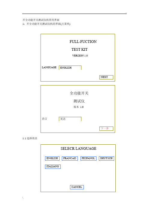
开全功能开关测试仪机常用界面1:开全功能开关测试仪机的界面(主菜单)1-1选择英语2,在1选择下一步2.1 选择测试仪配置参数选择(触摸屏的参数为单循环)2.2.1 选择断路器测试仪(下面的参数一部分是由开关直接得到(触摸屏的底色为白色部分)另一部分是自己根据开关选择的(底色为黑色部分))(国标选择IEC)注——白色底部分是默认的,不需要设置。
①控制单元(脱扣单元):默认为MICRO-LOGIC,不需设置。
②控制单元类型:按照开关默认的,如显示的是2.0、5.0、6.0或7.0,不需设置。
③断路器:选MASTER-PACT④断路器型号:A、开关型号为MT06N1~MT16N1对应选NT06~NT16B、开关型号为MT08N2~MT25N2对应选NW08~NW25C、开关型号为MT08H1~MT63H1对应选NW08~NW63D、开关型号为MT08H1b~MT63H1b对应选NW08~NW63E、开关型号为MT08H2~MT63H2对应选NW08~NW63⑤国标:选IEC。
⑥分断能力:按照开关设置,如开关是N1、H1(H1、N2、H1b是通用的)、H2。
⑦额定电流:按照开关默认的,不需要设置。
2.2.2 在22.2.3 在2.2.2中选择自动测试曲线lr 长延时tr 长延时(反时限)idmtllsd 短延时tsd 短延时(反时限)li 瞬时脱扣lg 接地故障tg保护参数配置表:按照开关默认的参数,不需要设置。
2.2.4 在2.2.3中选择下一步得(这脱扣的种类看开关)2.2.5 在2.2.4中选择下一步得2.2.6 在22.2.7 在2.2.6中得存储类型选CERATE 就可以了2.2.8 在2.2.6中选下一步进入存储文件界面。

ATMT自动电源转换系统用户手册下面的符号将用于本手册的说明,提醒您注意潜在的危险,或者请您注意那些阐述、简化过程和关键操作。
开关的不可恢复性损坏。
X: 关键性操作,提示您使用不当时,可能使控制器工作于非正常状态。
请注意:电气设备应该让有资格的专业人员进行安装、操作、使用、维护。
未按使用手册操作而造成的不良后果,施耐德电气公司将不负任何责任。
目录一、控制器介绍 (1)1. 符合标准 (1)2. 污染等级 (1)3. 抗湿热等级 (1)4. 电磁兼容性 (1)5. 安装与操作指南 (1)6. 安全信息 (1)7. 控制器类型 (1)二、控制器操作及参数设置 (3)1. 2A/2B控制器面板介绍 (3)2. 3A/3B控制器面板介绍 (4)3. 显示及设置 (5)三、控制器端子说明 (11)四、安装及接线 (12)1. 控制器外形及安装尺寸 (12)2. 适配器外形及安装尺寸 (13)3. 适配器与开关接线图 (15)4. 2A/2B整体安装图 (16)5. 3A/3B整体安装图 (17)一、控制器介绍1.符合标准•GB14048.1-2006 低压开关设备和控制设备:总则•GB14048. 2-2008 低压开关设备和控制设备:断路器•GB/T14048.11-2008 低压开关设备和控制设备:多功能电器转换开关电器•IEC60947:2005 Low-voltage switchgear and controlgear•IEC60947-2:2005 Low-voltage switchgear and controlgear: Breakers•IEC60947-6-1:2005 Low-voltage switchgear and controlgear: Multiple function equipment- Transfer switching equipment2.污染等级•Level33.抗湿热等级A TMT已通过下列标准所规定的严格环境条件下的试验•IEC60068-2-1 干冷环境(-5℃)•IEC60068-2-1 干热环境(+40℃)•IEC60068-2 低温4.电磁兼容性•辐射等级B级执行标准GB4824(CISPR11)•静电放电空气放电Level3;接触放电Level2 执行标准GB1 7626.2-2006(IEC61000-4-2)•射频电磁场LE VEL3 执行标准GB1 7626. 3-2006 (IEC61000-4-3)和GB1 7626.6-2006 (IEC61000-4-6)•电快速瞬变脉冲群LE VEL3 执行标准GB1 7626.4-2008 (IEC61000-4-4)•浪涌LE VEL3 执行标准GB1 7626. 5-2008 (IEC61000-4-5)5.安装与操作指南即使控制单元处于待机状态,在手动操作断路器前需要将其断电,它可能在没有任何警告的情况下操作断路器。
测高仪的使用方法测高仪是一种用于测量高度的仪器,主要应用于建筑、土木工程和测量等领域。
测高仪的使用方法可以分为以下几个步骤:1. 预备工作首先,准备好测高仪和相关配件,如三脚架、防护罩等。
确保测高仪的电池有足够的电量,并检查仪器的各个部件是否完好。
若需要室外使用,还需保证气象条件适宜。
2. 安装测高仪将测高仪放在一个平坦的地面上,安装好三脚架。
根据测高仪的型号和仪器说明书,正确调整三脚架的高度,使测高仪与被测物体在一个平面上。
确保测高仪稳固固定在三脚架上。
3. 校准仪器在使用测高仪之前,需要对其进行校准。
校准的目的是保证测高仪的测量结果准确可靠。
校准时,将测高仪放在已知高度的基准面上,按照仪器说明书中的方法进行操作。
校准操作包括激光线的水平调整、零点校准和仪器检测等。
4. 进行测量将测高仪对准待测高物体,观察测高仪上的显示屏或指针。
根据仪器型号不同,显示屏上可能会显示出测量结果或者电子数字。
将测量结果记录下来。
5. 移动测高仪在测量过程中,可能需要对测高仪进行移动。
在移动之前,务必将测高仪稳固固定在三脚架上,并确保仪器的水平度。
6. 关机和存储在使用完毕后,将测高仪关机。
根据仪器说明书,将测量结果导出或保存在仪器内部存储器中(如果有的话)。
同时,注意将测高仪和配件进行整理和保养,以延长仪器的使用寿命。
需要注意的是,每种测高仪的使用方法可能会稍有不同,具体操作应根据仪器的说明书来进行。
此外,使用测高仪时也要注意安全,避免直接照射激光线到眼睛,以免造成损伤。
在室外使用时,还要注意环境因素的影响,如大风、雨雪等天气状况。
总之,测高仪是一种重要的测量工具,在建筑和土木工程等领域有着广泛的应用。
正确使用测高仪,并按照仪器说明书进行操作,可以获得准确可靠的测量结果,提高工作效率。

美泰MT160超声波测厚仪∙产品型号:MT160∙参考价格:面议∙厂商性质:生产商∙品牌:美泰∙产地:北京∙3I 指数:768∙典型用户:0详细信息详细介绍1 概述MT160仪器是智能型超声波测厚仪,采用最新的高性能、低功耗微处理器技术,基于超声波测量原理,可以测量金属及其它多种材料的厚度,并可以对材料的声速进行测量。
可以对生产设备中各种管道和压力容器进行厚度测量,监测它们在使用过程中受腐蚀后的减薄程度,也可以对各种板材和各种加工零件作精确测量。
本仪器可广泛应用于石油、化工、冶金、造船、航空、航天等各个领域。
2 技术参数*显示方法:高对比度的段码液晶显示,高亮度EL背光;*测量范围:0.75~300mm(钢中),公制与英制可选择;*声速范围:1000~9999 m/s:*分辨率:0.1mm /0.01mm*示值精度:±(0.5%H+0.04)mm H为被测物实际厚度*测量周期:单点测量时4次/秒、扫描模式10次/秒;*存储容量:可存储20组(每组最多99个测量值)厚度测量数据。
*工作电压:3V(2节AA尺寸碱性电池串联)*持续工作时间:约100小时(不开背光时)*外形尺寸:150×74×32 mm*整机重量:245g3 主要功能*适合测量金属(如钢、铸铁、铝、铜等)、塑料、陶瓷、玻璃、玻璃纤维及其他任何超声波的良导体的厚度;*可配备多种不同频率、不同晶片尺寸的双晶探头使用;*具有探头零点校准、两点校准功能, 可对系统误差进行自动修正;*已知厚度可以反测声速,以提高测量精度;*具有耦合状态提示功能;*有EL背光显示,方便在光线昏暗环境中使用;*有剩余电量指示功能,可实时显示电池剩余电量;*具有自动休眠、自动关机等节电功能;*小巧、便携、可靠性高,适用于恶劣的操作环境,抗振动、冲击和电磁干扰;*带RS232接口,支持现场打印机;4 工作原理本超声波测厚仪对厚度的测量,是由探头产生超声波脉冲透过耦合剂到达被测体,一部分超声信号被物体底面反射,探头接收由被测体底面反射的回波,精确地计算超声波的往返时间,并按下式计算厚度值,再将计算结果显示出来。

INSTRUCTION MANUALRemote Meter: MT50Thank you very much for selecting our product!This manual offers important information and suggestions with respect to installation, use and troubleshooting, etc. Please read this manual carefully before using the product.Remote MeterMT501 Important Safety Instructions (1)2 General Information (2)2.1 Features (2)2.2Main functions (3)2.3Recommendations (3)3 Installation (4)4 Product Features (8)5 Operation (12)5.1 Buttons (12)5.2 Main menu (13)5.3Real-time monitoring (14)5.4 Device information (16)5.5Test operation (16)5.6Control parameter (17)5.7Load setting (21)5.8Device parameter (24)5.9Device password (25)5.10Factory reset (25)5.11Failure information (26)5.12Meter parameter (27)6 T echnical Specifications (28)1 Important Safety InstructionsSAVE THESE INSTRUCTIONS:This manual contains important safety, installation and operating instructions for the Remote Meter.General safety information■Please inspect the MT50 thoroughly after it is delivered. If any damage is seen, please notify the shipping company or our company immediately. A photo of the damage may be helpful.■Read all instructions and cautions in the manual before starting the installation.■Keep the MT50 away from rain, exposure, severe dust, vibrations, corrosive gas and intense electromagnetic interference.■Do not allow water to enter remote meter.■There are no user serviceable parts inside the controller. Do not disassemble or attempt to repair it.2 General Information2.1 FeaturesThe new-generation remote display unit MT50 for the controllers is an associated display device which supports both the latest communication protocol and the voltage technology standard of solar controllers. The products have many excellent functions:■Automatic identify and display the type, model and relevant parameter data of controllers;■Real-time display the operational data and working status of the connection devices in digital, graphic and textual forms by a large-screen multifunction LCD;■Direct, convenient and rapid operation of six navigation function keys;■Both data and power flowing on the same lead, no need for external power;■Real-time data monitoring and remote load switchover of the controllers, and data browse and modification of device parameters, charge control parameters and load control parameters;■Real-time display of failure information of the connection devices;■Longer communication distance based on RS485.2.2 Main functionsFunctions like the real-time monitoring of the operational data and working status of a controller, the browse and modification of charge/discharge control parameters, the setting of device parameters and load control parameters and the restoration of factory defaults, based on LCD display and functional key operation.2.3 Recommendations■Please do not install MT50 in a situation with strong electromagnetic interference.3 InstallationFrame Mount Dimensions(mm)Wall installation steps:Step1: Locate and drill screw holesbased on the Frame Mounting dimensionof the base, and erect the plasticexpansion bolts;Step 2: Use four ST4.2×32 self-tappingscrews to fix the Frame;Frame MountingStep 3: Use four M4×8 pan head screws to mount MT50 Surface on the Frame;Step 4: Mount the four associated screw plugs into the screw holes.Surface MountingSteps of surface mounting:Step 1: Locate and drill screw holes based on the installation size of the Surface;Step 2: Use four M4×8 cross recessed pan head screws with M4 nuts to mount MT50 Surface onto the panel;Step 3: Mount the four associated white screw plugs into the screw holes.Surface mountingNote: Take full consideration of the plugging/unplugging space of the communication cable and the length of the cable during installation to see if they are appropriate.4 Product FeaturesRS485 communication and power interfaceRear ViewFailure indicatorFailure indicator flashes in case of failure of the connection devices. For failure information please check the Controller Manual.Communication indicatorIndicate communication status when MT50 is connected with the controller. Display screenMan-machine interaction operation interface.ButtonsThe Meter buttons includes four navigation buttons and two operational buttons. See the specific directions in the Operational Manual.RJ45 communication and power interfacesCommunication and power supply cable interfaces, used for communication connection with controllers.Note: Please use the communication plug which is marked with “MT”to connect MT50Monitoring screenDay and night icons-Night,- Day: The threshold voltage is 1V. Higher than 1V is daytime. Charge current iconThe icon is dynamically if there is charge current.Battery iconThe battery capacity is dynamically displayedNote: When the battery is in over discharge status, the icon displayed is“ ”.Battery status icons-Normal voltage, -Under voltage, -Over discharge.Load current iconThe icon is dynamically if there is discharge current.Load status icon- Load On, - Load Off.Note: In Manual Mode, pressing the "OK" button will switch the load status between "ON" and "OFF"5 Operation5.1 ButtonsThe buttons are respectively (from left to right) “ESC”,“Left”,“Up”,“Down”,“Right”and “O K “buttons, the operation is described in the schematic operation diagram below:Schematic operation diagramThe default entry page is the browse mode. Pressing button and inputting the correct password to enter the modification mode; and buttons could be used to move the cursor, and buttons could be used to modify the parameter values when the cursor is located at the current place;and buttons could be finally used to respectively confirm and cancel the modification of the control parameters.5.2 Main menuEnter the Main Menu by pressing "Esc".“Up”and “Down”buttons are respectively used to move the cursor to select the menu items, “OK”and “ESC”buttons are respectively used to enter or exit the corresponding pages of the menu items.5.3 Real-time monitoringThere are 14 pages under real-time monitoring. Please check it as below:17.5V 13.8V 13.8VOperational tips:Move between rows by pressing "Up" or "Down" buttons. Move along a row by pressing "Right" or "Left" buttons .5.4 Device informationThe product model, parameters and SN code of the controllers are displayed below:Operational tips: and buttons are respectively used to turn the browse page upward and downward.5.5 Test operationLoad switch test operation is conducted on the connection solar controller to see if the load output is normal. The test operation does not affect the working settings under actual load, which means that the solar controller will exit from the test mode when exiting the operational interface of the test.Operational tips: Enter the page and input correct password; use andbuttons to modify the On/Off status values, while use andbuttonsrespectively to confirm and cancel the test operation.5.6 Control parameterBrowse and modification operations are conducted over the control parameters of solar charge controller. See the scope of parameter modification in control parameters table, and the page of control parametersBattery voltage parameters(Parameters is in 12V system at 25℃ , please use X 2 in 24V, X 3 in 36 V, and X 4 in 48 V system)Notes:1. When the battery type is sealed, gel, flooded, the adjusting range of equalize duration is 0 to180min and boost duration is 10 to180min.2. The following rules must be observed when modify the parameters value in user battery type (factory default value is the same as sealed type):a) Over Voltage Disconnect Voltage > Charging Limit Voltage ≥ Equalize Charging Voltage ≥ Boost Charging Voltage ≥ Float Charging Voltage > Boost Voltage Reconnect.b) Over Voltage Disconnect Voltage > Over Voltage Reconnect Voltagec) Low Voltage Reconnect Voltage > Low Voltage Disconnect Voltage ≥ Discharging Limit Voltage.d) Under Voltage Warning Recover Voltage > Under Voltage Warning Voltage ≥ Discharging Limit Voltage.e) Boost Voltage Reconnect > Low Voltage Reconnect Voltage.NOTE: Please refer to user guide or contact with the sales for thedetail of setting operation.5.7 Load settingThe page of load setting could be used to set the four load working modes of the connection solar controller (Manual, Light on/off, Light on+timer, Time control)④Time control5.8 Device parameterThe software version information of solar charge controller could be checked via the page of device parameters, and device data like device ID, device LCD backlight time and device clock could be checked and modified. The page of device parameter in the diagram below:Note: the bigger the ID value of the connection device, the longer the Meter5.9 Device passwordThe password of the solar charge controller could be modified via the page of device password; the device password is a 6-digit figure which is required before entering the modification mode of “Control parameter”,“Load setting”, “Device parameter”,“Device password”,“Factory reset” pages. The page of device password in the diagram below:Note: Solar charge controller default password is”000000”5.10 Factory resetThe default parameter values of solar charge controller could be restored via the Factory reset page, which means the “Control parameter”,“Load setting”, “Charge mode” and “Device password” of the devices could be restored to the factory defaults (the factory default password of the devices is “000000”).5.11 Failure informationThe current failure information of the solar charge controller could be checked via the Failure information page (a maximum of 15 failure messages could be displayed); when the failures of solar charge controller are eliminated, the corresponding failure information will also be automatically eliminated.5.12 Meter parameterThe meter model, software and hardware version, and SN NO. could be checked via Meter parameter page. And the three parameters (Switch pages, Backlight) could be browsed and modified as well.Note: When the set up is accomplished, the auto switch page cannot6 Technical Specifications Electrical ParameterEnvironmental ParameterDefinitions of interface pinsData cable pin definitionsREMOTE METER DIMENSIONS (mm)Any changes without prior notice! Version number:V2.3。

3B SCIENTIFIC ®PHYSICS1003314 (230 V, 50/60 Hz)Bedienungsanleitung10/15 ALF1 Teslameter2 MagnetfeldsondeDas Teslameter, 20 mT, 200 mT entspricht den Sicherheitsbestimmungen für elektrische Mess-, Steuer-, Regel- und Laborgeräte nach DIN EN 61010 Teil 1 und ist nach Schutzklasse II aufge-baut. Es ist für den Betrieb in trockenen Räumen vorgesehen, die für elektrische Betriebsmittel geeignet sind.Bei bestimmungsgemäßem Gebrauch ist der sichere Betrieb des Gerätes gewährleistet. Die Sicherheit ist jedoch nicht garantiert, wenn das Gerät unsachgemäß bedient oder unachtsam behandelt wird.Wenn anzunehmen ist, dass ein gefahrloser Be-trieb nicht mehr möglich ist (z.B. bei sichtbaren Schäden), ist das Gerät unverzüglich außer Be-trieb zu setzen.∙ Vor Erstinbetriebnahme überprüfen, ob derauf der Gehäuserückseite aufgedruckte Wert für die Netzanschlussspannung den örtlichen Anforderungen entspricht.∙ Vor Inbetriebnahme das Gehäuse und dieNetzleitung auf Beschädigungen untersuchen und bei Funktionsstörungen oder sichtbarenSchäden das Gerät außer Betrieb setzen und gegen unbeabsichtigten Betrieb sichern.∙Gerät nurdurch eine Elektrofachkraft öffnen lassen.Das Teslameter dient zur Messung der Fluss-dichte in magnetischen Gleichfeldern.Das Gerät beinhaltet einen Hallsensor zur Mes-sung axialer und tangentialer Magnetfelder bis zu 200 mT. Die Magnetfeldsonde ist zur Abstands-messung mit einer metrischen Skala versehen. Neben der digitalen Anzeige des Magnetfelds liefert das Gerät auch eine zum Magnetfeld pro-portionale Spannung, die einem Datenlogger, einem XY-Schreiber oder einem analogen Multi-meter zugeführt werden kann.Das Teslameter ist in zwei Spannungsversionen erhältlich. Das Gerät mit der Artikelnummer 1003313 ist für eine Netzspannung von 115 V (±10 %) ausgelegt, das Gerät mit der Artikel-nummer 1003314 für eine Netzspannung von 230 V (±10 %).2.1Bedienelemente1 Anschlussbuchse für Magnetfeldsonde2 Digitalanzeige3 Messbereichswahlschalter 20 mT4 Messbereichswahlschalter 200 mT5Messmoduswahlschalter axial (B X ) und tangential (B Z )6 Nullpunktsteller B X mit LED Betriebsanzeige7 Nullpunktsteller B Z mit LED Betriebsanzeige8 Ausgangsbuchse für Messmodus B X9 Massebuchse10 Ausgangsbuchse für Messmodus B Z 11 Ein-/AusschalterMagnetfeldsonde: 1 tangentiale Hallsonde (z-Richtung), 2 axiale Hallsonde (x-Richtung), 3 TrägerMessbereich 20 mT Auflösung: 0,01 mT Genauigkeit: 2 % ±3 digits Messbereich 200 mT Auflösung: 0,1 mT Genauigkeit: 2 % ±1 digits Anzeige: 3½-stelliges LCD mit Vor- zeichen für die Feldrich- tung Ziffernhöhe: 13 mm Eingang: BNC-Buchse Ausgang: 4-mm-Sicherheitsbuchsen Ausgangsspannung: 10 mV / mT (20 mT) 1 mV / mT (200 mT) Abmessungen Gerät: 205 x 230 x 85 mm³ Abmessungen Sonde: 360 x 15 x 25 mm³4.1 NullpunkteinstellungEs empfiehlt sich, den Nullpunktabgleich im Messbereich 20 mT vorzunehmen. Beim an-schließenden Umschalten in den größeren Messbereich ist dann kein neuer Abgleich erfor-derlich.Wenn Magnetfelder von Permanentmagneten gemessen werden sollen, ist der Nullpunktab-gleich in ausreichendem Abstand vom Magneten durchzuführen.Wenn die Felder stromdurchflossener Leiter ge-messen werden sollen, ist es empfehlenswert die Sonde bei abgeschaltetem Magnetfeldstrom am vorgesehenen Messort zu positionieren.∙ Magnetfeldsonde an der Anschlussbuchse 1anschließen.∙ Messmodus 20 mT wählen.∙ Nullpunktsteller so lange drehen, bis die Nulloder ein möglichst kleiner Wert im Anzeigefeld erscheint.4.2 Messung axialer MagnetfelderMit der axialen Hallsonde wird die Komponente der magnetischen Induktion in Richtung der Son-denachse gemessen.Zusätzlich kann die Feldrichtung erkannt werden: Zeigt das Feld in die Richtung des Sondenträgers (z.B. vor dem Nordpol eines Stabmagneten), so ist der angezeigte Wert positiv, bei umgekehrter Ori-entierung negativ.4.3 Messung tangentialer MagnetfelderMit der tangentialen Hallsonde wird die Kompo-nente der magnetischen Induktion, die senkrecht zur Trägerplatte orientiert ist, gemessen.Zusätzlich kann die Feldrichtung erkannt werden: Eine positive Anzeige bedeutet, dass das Feld aus der Richtung der Trägeroberfläche mit Skala kommend in die Sonde eintritt, während ein ne-gativer Wert auf die umgekehrte Feldrichtung hinweist.4.4 Benutzung des AnalogausgangsÜber die Ausgangsbuchsen (8, 9, 10) kann eine zum Magnetfeld proportionale Spannung exter-nen Messgeräten (Datenlogger, XY-Schreiber,analoge Multimeter) zugeführt werden. Die Aus-gangsspannung korrespondiert mit der Digitalan-zeige. Sie beträgt 10 mV pro mT Messwert im 20mT-Bereich und 1 mV pro mT Messwert im 200mT-Bereich.∙Gerät an einem sauberen, trockenen undstaubfreien Platz aufbewahren.∙Vor der Reinigung Gerät von der Stromver-sorgung trennen.∙Zur Reinigung keine aggressiven Reinigeroder Lösungsmittel verwenden.∙Zum Reinigen ein weiches, feuchtes Tuchbenutzen.∙Die Verpackung ist bei den örtlichen Recyc-lingstellen zu entsorgen.∙Sofern das Gerätselbst verschrottetwerden soll, so gehörtdieses nicht in dennormalen Hausmüll.Es sind die lokalenVorschriften zur Ent-sorgung von Elektro-schrott einzuhalten.3B Scientific GmbH ▪ Rudorffweg 8 ▪ 21031 Hamburg ▪ Deutschland ▪ 。

测高仪操作说明范文测高仪是一种用于测量高度的仪器,广泛应用于建筑、工程和地质测量等领域。
正确的操作测高仪可以确保测量结果的准确性和可靠性。
下面是测高仪的操作说明:1.准备工作a.检查测高仪的各部件是否完好,并确保电池电量充足。
b.将测高仪放在水平稳定的地面上,并开启电源。
2.设置测量单位a.根据需要选择合适的测量单位,例如米、英尺或百分比。
这一步骤可以根据具体仪器的型号和厂家说明进行设置。
3.校准仪器a.在使用之前,需要进行仪器的校准。
校准可以通过使用参考物体(如已知高度的建筑物或测量棒)进行。
在使用参考物体进行校准时,将测高仪指向参考物体顶部,并按下“校准”按钮进行校准操作。
4.进行测量a.将测高仪指向所需测量位置的顶部,确保仪器在稳定的状态下进行测量。
b.按下“测量”按钮进行测量,仪器会显示测量结果。
5.记录和处理测量结果a.将测量结果记录下来,可以使用纸笔或者直接将结果输入到计算机等设备中。
b.如果需要对测量结果进行进一步的处理和分析,可以使用专业的数据处理软件进行操作。
6.定期维护和保养a.清洁仪器的外表面和镜头,确保仪器的正常运行。
b.更换电池并注意电池的使用寿命,及时更换以保证仪器的正常使用。
c.定期检查仪器的各个部件是否正常,如有损坏或故障应及时修复或更换。
在操作测高仪时,还应注意以下几点:-对于精确的测量,应尽量避免在强风或恶劣天气条件下使用测高仪。
-在进行测量时,要保持仪器的稳定,并避免晃动和震动。
-在仪器的使用过程中,要注意避免遮挡物体和反光物体,以防影响测量结果的准确性。
-当测量不同高度时,应及时校准测高仪。
-如果测量结果出现异常,应检查仪器是否正常,如有必要可以重新进行校准。
总之,正确的操作测高仪对于获得准确的测量结果至关重要。
遵循上述操作说明,并注意维护和保养测高仪,可以确保仪器的长期稳定和准确性。

高度测量仪器使用方法英文回答:To use a height measuring instrument, there are several steps you need to follow. First, make sure the instrumentis set up properly and calibrated. This may involve adjusting the zero point or ensuring the instrument is level. Once the instrument is set up, you can begin taking measurements.To measure the height of an object, place the instrument on a stable surface and position it at the base of the object. Look through the viewfinder or digital display to align the instrument with the top of the object. Some height measuring instruments may have a laser or other targeting feature to assist with alignment. Once the instrument is aligned, record the measurement displayed on the instrument.It is important to note that different height measuringinstruments may have specific instructions or features, soit's always a good idea to consult the user manual for the specific instrument you are using. Additionally, it's important to ensure the instrument is used in a consistent manner for accurate and reliable measurements.For example, let's say I am using a digital height measuring instrument to measure the height of a doorframe.I would set up the instrument on a flat surface and ensureit is calibrated. Then, I would position the instrument at the base of the doorframe and align it with the top of the frame using the viewfinder. Once aligned, I would recordthe measurement displayed on the instrument, which might be something like 2.1 meters.中文回答:使用高度测量仪器时,需要按照以下几个步骤进行操作。
测高器的使用方法测高器是一种常用的测量工具,可以用于测量物体的高度。
它常用于建筑、工程和地理测量等领域。
下面将介绍测高器的使用方法。
一、准备工作在使用测高器之前,首先需要进行一些准备工作。
首先,确保测高器的电源充足,并按照说明书正确连接电源。
其次,检查测高器的各个部件是否完好,如电源线、显示屏等。
最后,选择合适的测量位置和测量对象,确保能够准确测量到所需的高度。
二、测高器的设置在开始测量之前,需要对测高器进行一些设置。
首先,根据实际情况选择合适的测量单位,如米、厘米等。
其次,根据测量对象的特点,选择合适的测量模式,如单次测量、连续测量等。
最后,根据测量环境的亮度情况,调节测高器的背光亮度,以确保能够清晰地读取测量结果。
三、测量操作在进行测量时,需要注意以下几点。
首先,保持测高器与测量对象之间的垂直关系,以确保测量结果的准确性。
其次,将测高器的测量探头对准测量对象的底部或顶部,确保探头与测量对象有良好的接触。
然后,触发测量按钮,等待测量结果的显示。
最后,根据测量结果进行记录或进一步处理。
四、测量结果的读取与处理在测量完成后,需要读取并处理测量结果。
首先,注意观察测高器显示屏上的测量数值,确保读取准确。
其次,根据需要,可将测量结果进行转换或计算,如将米转换为厘米、进行平均值计算等。
最后,根据测量结果的准确性和精度要求,决定是否需要进行进一步的校验或重复测量。
五、注意事项在使用测高器时,还需要注意以下几点。
首先,避免将测高器暴露在潮湿、高温或强磁场等恶劣环境中,以免对测量结果产生影响。
其次,在测量过程中,保持稳定的测量姿势,避免手部晃动或测量过程中的干扰。
最后,及时清洁和保养测高器,以确保其长期的稳定工作。
测高器是一种常用的测量工具,使用方法相对简单。
通过正确的准备工作、测量设置和测量操作,可以准确地测量物体的高度,并对测量结果进行适当的处理和记录。
在使用测高器时,需要注意遵循操作规范,并注意维护和保养测高器,以确保其长期的准确性和可靠性。

测高仪CHM6000架空线测高仪操作说明一、功能键说明R阅读键:依次读取所测第一至第六根导线的读数。
M测量健按一下即完成全部测量功能。
Auto/Off电源开关:按一下打开电源,不按任何键三分钟后,电源自动关闭。
R和M健同时按这两个键,消除所有数据。
TOP/BTM开关:在TOP位置,测离地最高第六至第一根导线。
在BTM位置,测离地最低第一至第六根导线。
Mea/Cal开关:在Mea位置,仪器测架空导线;在Cal位置,仪器测室内距离或其他大物体的距离,也可以测标准物体的距离,作为检验仪器精度的依据。
二操作步骤1.打开ON键。
2.站在导线下方与导线平行位置。
3.等显示屏温度值与大气温度一致。
4.如果测导线高度,把Mea/Cal开关定到Mea位置,如果测离地最低第一至第六根导线,把TOP/BTM开关定到下档,如果测离地最高至第一根导线,把该开关定到上档。
5.两手水平握稳测高仪(也可置于水平地面),按下M键,约2-3秒后松开。
6.按R即显示测量值。
如TOP/BTM开关在下档,显示屏按顺序显示离地最近的导线与仪器底部的距离,第一根线与第二根线的距离,第三根线与第二根线的距离……如所测的导线数量不够六根,显示值为——。
如TOP/BTM开关在上档,显示屏按顺序显示离地最高的导线与仪器底部的距离,第六根导线与第五根导线的距离,第五根导线与第四根导线的距离……(注:该值前面有"-”符号,表示负值),其余依次类推。
7.同时按R和M键,清除所有数据。
三、电池低电压报警和更换电池1.电池电压低于6V,仪器会自动报警,并在显示屏中间上方有显示。
用户应及时更换电池,否则测量值不准,电池漏液会严重损坏仪器。
2.电池盒在仪器左下方,滑开盖后,取出9V旧电池,注意极性,换上新电池,再盖上盖子。
四、其他注意事项1.CHM6000系列测高仪显示单位为公制,不需要英制/公制转换。
2.理论上讲,CHM6000仪器在大气温度摄氏20度时,测量范围3-30米该仪器工作原理是超声波反射测距,而实测范围是随大气温度而变化,但精确不受影响。
Mestro-touch 中文使用说明书1 安全规章1.1 重要通告为了防止任何误操作引起的损坏,请仔细阅读下列说明。
任何由不符合本操作手册的不当用法而造成的损坏,TRIMOS均不承担责任。
1.2 安全符号本手册使用以下安全符号一般警告,使用建议电击危险静电防护1.3 一般警告静电防护静电能损坏仪器的电子器件。
为防止此类损坏,避免任何与连接器插脚的接触。
打开电源仪器只有在接电线路已经完全正确时才可打开。
为防止任何意外或性能的改变,仪器不能被拆卸。
电子显示单元含有高压元件,不论任何原因,需要时,电子单元只有授权人员才可以打开。
不要使仪器及其元件,附件受雨淋或溅入任何液体。
避免外界物质进入连接器和仪器通路。
当仪器或其任何部件发生问题(无显示,过热,异味…),立即关闭仪器,断开电源。
请联系当地这是一个高度精确的仪器,操作期间应特别小心。
主要包括以下几点:-在稳定,平坦,洁净表面使用仪器.-避免任何震动以免仪器性能特征降低- 在无震动地方使用仪器使用- 避免阳光直射和过分潮湿- 避免接近加热或空调系统- 参考要求的环境条件2 仪器说明 2.1仪器结构2.1 2。
1 2.21416 158975 43 216122.113 2.428293031 32 33 34 35 36 18 19 212220 232425 26 17 2.327 10111.立柱2.上测头夹持器3.浮动测头悬浮系统调整螺钉4.锁定测头悬浮(镀珞)运输安全螺丝5.测力调整螺丝6.下测头夹持器7.测头8.仪器移动气垫底座9.仪器移动操作手柄10.气垫激活按纽11.可编程功能键12.测量托架与测头移动手柄(自动版)13.显示单元(见后面详细资料)2.2 测量拖架与测头手柄(手动版)14.测量拖架与测头手柄(手动版)15.微调激活锁定装置16.微调螺丝2.3 显示单元17.选择基准/数字7/字母abc选择精度/数字8/字母def测头常数存贮/数字9/字母ghi选择测量单位(毫米/英寸)/数字4/字母jkl最大,最小或差值模式/数字5/字母置零/数字6/字母pqr垂直度检测/数字1/字母角度测量/数字2/字母选择计算模式/数字3/字母yz选择公差限定模式/数字0/ /数字0全部清除缓冲区模式/十进制小数点显示清除缓冲区前值/改变标记18.设置当前基准的前次输入预设值19.数据打印输出20.输入数据确认21.主功能选择22.移动光标至前面区域移动光标至后面区域23.开/关键(电源开/关)24.测头设置方向指示25.绿灯:测量值在指定公差内红灯:测量值超出指定公差橙色:尺寸超出指定公差,但零件可修改26.功能键27.显示器(Vetra-Touch和Mestra-Touch触摸屏)2.4 接口/连接器28.X轴(水平的,电子测量垂直度)29.Z轴(垂直的)30.“仪器”连接器31.RS232插针32.RS 232 插孔33.交流电源适配器接口B AB B36.脚踏板连接器3 开始3.1 装箱单仪器的标准配置包括:1.仪器2.显示单元3.触摸笔4.交流电源适配器5.电源线6.碳化钨测头, 4mm7.设置量规8.保护盖9.2mm六角改锥10.5mm六角扳手11.2个螺钉(固定显示单元)12.用户手册13.电气连接图14.检验证书15.质量保证书当打开包装,用手搬运仪器的手柄和立柱,请保留包装箱以便于将来搬运。
如果仪器的储存温度低于5°C,开箱前在室内常温放置几个小时,以防止冷缩影响仪器的传感器。
3.2 安装拆箱后,做以下准备:1. 用净布,浸过少许酒精清洗底座下的气垫衬垫位置。
2. 将仪器小心放在干净的测量平台上。
3. 用2个螺钉安装显示单元(6mm六角头螺钉)。
静电能损坏仪器的电子元件。
为防止此类损坏,不要接触接口针脚。
4. 连接测量系统到显示单元。
5. 连接功能系统到显示单元。
6. 将测头滑进固定器(1)并用旋钮(2)锁紧。
7. 松开运输安全螺钉(镀铬)。
8. 给电池充电。
连接AC适配器与仪器。
AC适配器接好后,即使仪器已关机也会自动打开。
电池充电电量显示在屏幕上。
(见§ 11.4)。
完全无电的电池需要3小时充满。
其它所有电路接好前不要连接充电线路。
见上面说明。
为了能延长电池组的使用时寿命及保持充足的电力,仪器初次使用时必须做5次完整的充放电。
仪器在插上AC适配器后即可使用,不必等到电池完全充满。
AC适配器长时间接通不会产生危险。
4 开始4.1 操作设置§ 11节将给出应用及调整的详细信息。
1. 按On/Off键打开仪器。
按On/Off键2秒钟以上关机。
2.显示器会提示参考面。
慢慢移动测头托架直到通过小三角形参考符号。
声音提示信号确认已经找到参考面,显示器开始记数。
如果显示器没有记数,重复此过程。
3.仪器现在需要测头常数。
此功能补偿向上或向下测量时(曲面,直径)测头的尺寸和偏斜。
将测头放在设定规的两个表面之间。
不要再移动仪器和设定规。
注意:此过程可以按.来中断。
这时使用上次存储的测头常数4.用手轮将测头放在设定规的下表面上,施加测力直到确认尺寸确认的绿色方向箭头和声音信号5. 不要移动任何部件(仪器及设定规),向上移动测头在上表面执行相同的步骤。
6. 再次重复4,5步。
这可消除由所使用的测头类型不同带来的尺寸不确定性。
显示器的分辨力自动适应尺寸的不确定性。
2 x 7.测头常数显示在屏幕上并存储进缓冲区(CST).仪器现在做好了使用准备。
每次更换测头,每次更换测头在固定器中的位置,每次调整测力或调整浮动测头悬挂系统后,测头常数都需检查并存储。
5 基本功能5.1 选择表面/直径和中心距尺寸要选择表面/直径和中心距尺寸模式,按Functions键或在触摸屏上直接选择。
最大,最小和差值模式及温度,高级功能等将在后面解释。
oror菜单功能5.2 表面测量1. 开机后,仪器设定在表面测量模式。
若不是这样,按Functions键或直接在触摸屏上选择。
or2. 设置显示器值为零或用测头测得的参考面的预设值(见§6.1 和§ 6.6)。
将测头放在参考表面上,施加测力直到出现尺寸确认的绿色方向箭头及声音信号。
按Zero 或Preset 键。
or3. 将测头放在下或上表面,施加测力直到出现尺寸确认的绿色方向箭头及声音信号。
结果将被显示并存入缓冲区(SUR)。
or表面直径/中心据Diameter / 最大,最小和差值Min / 温度Temperature帮助Help高级功能Advanced5.3 直径和中心距尺寸1. 设置屏幕值为零或为一参考面上的预设值。
or2. 通过按Functions键或直接在触摸屏上选择直径/中心距模式。
3a. 内径:将测头置于孔内并放在偏离中央的下轮廓面上(1)。
施加测力直到出现尺寸确认的绿色方向箭头及声音信号.随后移动仪器(或零件)确定拐点(2)。
拐点被自动存贮。
注意:当找到拐点后测头指示器(在显示器的左侧)在绿色区域内。
4a. 直接上移测头到上轮廓面(3)。
施加测力直到出现尺寸确认的绿色方向箭头及声音信号. 随后移动仪器(或零件)确定拐点(4)。
显示直径值。
3b. 外径:将测头放在偏离中央的下轮廓面上(1)。
施加测力直到出现尺寸确认的绿色方向箭头及声音信号.随后移动仪器(或零件)确定拐点(2)。
拐点被自动存贮。
从此面缓慢移开测头,偏离中央。
4b. 将测头放在偏离中央的上轮廓面上(3)。
施加测力直到出现尺寸确认的绿色方向箭头及声音信号.随后移动仪器(或零件)确定拐点(4)。
显示直径值。
5. 放开测头。
中心距值会在2秒显示后。
直径和中心距两个值存储在缓冲区(DIA 和CEN )。
6 第二功能6.1 参考值6.1.1 选择参考值显示单元上可使用4个参考值。
当前参考值显示在探测指示器上。
按Ref键改变参考值。
参考值的每次变化都显示在缓冲区内6.1.2 给参考值分配预设值通过按Preset键,先前输入的预设值(或零值)会分配给选定的参考值(1到4)。
参考值可以在表面或中心线尺寸上输入。
预设值可以分配给每个参考值。
> 2 秒按Preset键2秒以上来选择需要的参考值。
输入数值,按Enter键确认。
6.2 选择分辨率按Resol键改变屏幕分辨率。
6.3 设置/记忆测头常数为检查并记忆测头常数,按键并执行与“操作设置”相同的步骤(§ 4.1, 3 到7点).说明:按一次键,当前的测头常数值将被显示(或可输入新值)。
再按一次,将中断测头常数设定模式并且屏幕会自动切换回正常表面测量模式。
6.4 选择测量单位:毫米/英寸尺寸单位可以是毫米或英寸。
要改变单位,按mm/in键。
当前单位显示在探测指示器下。
可以锁定需要的测量单位(§ 9).6.5 最大/最小/差值测量模式最大/最小/差值模式总是使用与表面接触的测头。
允许测定以下值:Min:被测面的最小值or Max:被测面的最小值Delta:最大与最小值的差值要选择最大/最小/差值模式,按键盘的键或直接在触摸屏上选择。
通过按相同键(或符号)几次,就会显示所需的模式。
6.5.1 最大/最小值测量模式1. 选择最大/最小值模式。
"MIN" 或"MAX指示出现在显示图示的右边。
2.将测头放在待测面上,沿待测部分移动仪器(或零件)。
注意:通过按zero键,最大,最小值将被重新设定,并且实际托架位置值被显示。
3.测头移开后,最大最小值被存储并显示在缓冲区(MIN 或MAX).随后即可进行新的测量。
6.5.2 差值测量模式1. 选择差值模式。
“DELTA”指示出现在显示图示的右边。
2. 将测头放在待测面上,沿待测部分移动仪器(或零件)。
注意:通过按Zero键,差值模式被重设,屏幕显示零。
测头移开后,平面度(差值=最大值-最小值)被存储并显示在缓冲区(DLT).随后即可进行新的测量。
只要测头接触表面,可以通过按键选择最大/最小/差值模式。
相应的值也会被显示。
6.6 屏幕零值设定按Zero键设定屏幕零值(表面尺寸或中心线距离)。
6.7 垂直度检查垂直度检查包括屏幕图解所示的4个值z 距离⊥垂直度∠倾斜度—直线度垂直度按以下程序检测:1. 锁定浮动测头的移动(镀铬螺丝).2. 将TRIMOS电子测头及支架插入固定器定位孔内,用旋钮(2)锁定。
Z∠—z3. 将电子测头连接到显示单元。
3. 按键激活相应功能。
(测头)X轴值用大字表示,Z轴值在X轴值下用小字表示。
注意:如果测头未连接,会显示“Error X”。
X5. 将待测零件靠向电子测头,确保整个测量范围内保持接触。
移动测量托架到起始位置。
6. 按Zero键设置屏幕值为零。
Z 7. 沿待侧面缓慢移动测头。
在此过程中,Z轴值(垂直的)及X轴值(水平的)直接连续显示。