DZS3系列电磁失电制动器说明书
- 格式:pdf
- 大小:3.24 MB
- 文档页数:6
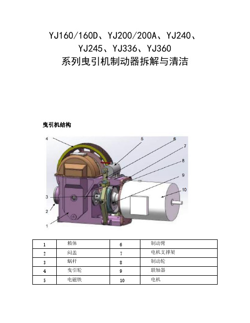
YJ160/160D、YJ200/200A、YJ240、YJ245、YJ336、YJ360系列曳引机制动器拆解与清洁曳引机结构制动器的调整、保养及使用DZS系列制动器的调整制动器的调整应在电梯检修状态下进行。
调整前请撕掉制动轮上的保护膜。
首先在停机状态下松开紧固螺母1,拧松调节螺栓2,使制动器在动作过程中微动开关不动作。
松闸起车运行,松开紧固螺母3,再稍微拧松调节螺栓4,至感觉到制动闸瓦磨擦制动盘,再缓慢上紧螺栓4,一直到曳引机在运行状态下制动闸瓦与制动盘不发生磨擦(平均间隙小于0.7mm,一般在0.4~0.5mm左右),然后拧紧锁紧螺母3。
停车,再拧紧调节螺栓2,至微动开关动作,在X方向手动微动开关要求开关动作后仍保留约1mm的空回程,然后拧紧锁紧螺母1。
同理再调整另一制动闸瓦。
接着再调整弹簧的初始负载以调节制动力。
拧松防松螺母5,增减弹簧6的压缩量至理想的制动效果后锁紧防松螺母5。
同理调整另一制动臂。
应当注意的是,制动器长期运行后闸瓦会磨损,微动开关的空回程会减少,弹簧的初始负载会降低,这样可能会导致制动器在工作过程中微动开关不动作或压坏微动开关、制动力减小等情况,只调整微动开关的工作行程与弹簧的初始压缩量都是不合适的,应当按上述要求重新调整。
DZS系列电磁铁维保操作●电磁铁维保前,须将空载轿厢置于井道顶部;对重置于井道底部固定,不得移动。
操作完毕后须切断电源。
●只有经过正确培训和指导的维保人员才能进行该操作。
一、电磁铁端盖螺栓固定结构拆卸电磁铁步骤1:使用卡钳取下挡圈、垫圈及弹簧。
步骤2:卸除端盖上的螺钉。
步骤3:旋转手柄将端盖顶出并取下。
步骤4:取出柱塞组件。
步骤5:使用卡钳取下挡圈,取下松闸杆。
维保检测项目步骤1:检查缓冲垫是否完整,若损坏须进行更换。
步骤2:检查柱塞表面油污,将表面擦拭干净;同时需清理制动器内部。
步骤3:a.检查柱塞头部磨损划痕情况,距端面15mm的圆周表面内磨损达70%以上,须更换柱塞;b.检查柱塞径向磨损,最大允许磨损深度为0.5mm,且磨损范围在圆周表面不能超过180度;若磨损超过0.5mm,须更换柱塞;c.检查顶杆径向磨损,最大允许磨损深度为0.3mm,若磨损超过0.3mm,须更换柱塞组件;d.柱塞及顶杆表面有未达到更换要求的磨损划痕,用砂纸修光且不得有台阶感。


●电磁铁维保前,须将空载轿厢置于井道顶部;对重置于井道底部(压在缓冲器上)固定,不得移动。
操作完毕后须切断电源。
●只有经过正确培训和指导的维保人员才能进行该操作。
1、拆卸制动臂组件1 3 2步骤1:在制动臂上卸除开关连接板,拆前请 做相应标记以便组装时按原有标记调整。
步骤2:完全松脱制动弹簧调节螺栓,操作前测量弹簧长度并进行相应标记,以便安装时按原位置调整。
步骤3:卸除关联件,旋转平置制动臂组件。
注:重复以上步骤将另一端制动臂组件拆除, 务必将两端制动臂全部打开,这样电磁铁中间 手动拨杆才能拆下,维保。
2、拆卸制动器配件1 2 5 3步骤1:使用卡钳取下挡圈,垫圈及弹簧,注意动作要轻,不要丢失相关部件。
步骤2:卸除端盖上螺钉。
重复以上动作将另一端端盖螺钉松脱,同时在端盖及壳体上作相应标记。
步骤3:压下手柄将端盖顶出,取下。
步骤4:取出柱塞组件。
步骤5:使用卡钳取下挡圈,取下松闸杆及手动拨杆。
拆开电磁铁端盖后相关部位的名称及操作情况参见下记照片:3、维保检测项目步骤1:清理电磁铁内部及松闸拨杆安装孔部杂质及附着物,查看电磁铁内部特别是导向套部位是否磨损,若磨损标准达到50%时则更换机座、线圈、导磁环一整体,其标准的界定为整个圆周上磨损的累计总长度是否超过圆周总长的50%, (该磨损标准的判断不涉及磨痕深度等),有50%以下磨损及锈蚀时,可使用相应牌号的砂纸打磨修复。
在导向套及松闸拨杆孔处涂一薄层二硫化钼,并将误涂到其它部位的清理干净(注意不要涂太厚,以避免流到线圈固定外壳或其它部位)。
清理前注:请使用MOLYKOTE G-n Plus Paste 二硫化钼,建议使用100g 袋装的。
步骤2:检查手动松闸杆两密封圈磨损情况,若损坏请更换。
如果手动松闸杆的材质为钢质等磁性材料,则更换为铜质等非磁性材料,如果非磁性材料的手动松闸杆两端转动部位及电磁铁壳体轴孔有磨损情况,请使用相应牌号的砂纸打磨,砂纸打磨方向与拨杆运动方向相同。

三、电磁刹车操作及维护保养规程Q/SH10250185-20041 范围本标准规定了电磁刹车的操作规程本标准适应于SDF系列、FDWS系列风冷式,DS系列及5030、6032、7040、7838水冷式电磁车的操作及维护保养。
2 技术参数2.1 风冷式电磁刹车技术参数见表12.2 水冷式电磁刹车技术参数购买表23.1 首次使用前应做绝缘测量,绝缘电阻应大于1MΩ。
3.2 检查盘车,刹车转子应转动灵活。
3.3 在刹车两侧轴承腔内注入锂基脂。
3.4 在牙嵌或齿式离合器的滑动与转动部分注入适量润滑脂。
3.5 呼吸孔畅通无油污。
3.6 油冷式控制柜内油质良好,油面距离上端盖20mm左右,保证内部电器元件浸入冷却油内。
3.7 控制箱各电器元件安装牢固。
3.8 司钻控制箱手柄牢固、灵活无卡滞。
3.9 保证控制箱与刹车主体接线正确牢固。
3.10 风冷式电磁刹车进排风门畅通无阻;风机转动灵活,报警装置完好。
3.11 水冷式电磁刹车准备充足的刹车冷却软化水,水压开关及报警装置完好。
4 启动4.1 闭合电源开头。
4.2 检查控制柜内指标灯状态及仪表参数,确认指标正确。
4.3 风冷式启动风机,水冷式启动水泵。
5 操作与运行5,1 在下钻过程中,用电磁刹车手柄控制下放速度。
5.2 运行中冷水温度与流量应符合要求,轴承升温不大于70℃,轴承处无冷却水渗出;刹车坚固件无松动;冷却风机运转正常,变压器及油冷式控制柜温度正常。
5.3 每次下钻前检查维护轴承、牙嵌、离合器、拨叉。
检查控制柜仪表,指标灯指标正常。
5.4 及时清除进排风口杂物。
5.5 下钻完毕后,风冷刹车应继续通风,刹车冷却后再关闭风机。
5.6 停机时关闭电源开关。
6 维护保养6.1 月检查维护6.1.1 检查连接电缆有无损伤、无老化现象,绝缘良好。
6,1,2 清除控制柜积尘,检查控制器触点。
6.1.3 测量变压器、控制柜、操作手柄的输入、输出电压、电流并做好记录。
6.1.4 清洗呼吸器。


Brakes, Clutches and Electronic ComponentsP/N 8-178-000-24effective: 04/06/11Marine MarineMaritimeNavySuitable for many shipboardand severe duty applications Suitable for many shipboard andsevere duty applicationsSuitable for many Coast Guard, shipboard and severe duty applications when “ductile iron”is speci fi edDesigned to MilitarySpeci fi cationCompliance(Note A)IEEE 45ABSIEEE 45ABS IEEE 45Federal Standard 46ABSMIL-B-16392C(Ships)Spring Set Operation(Note E)Armature Actuated Brake(AAB)Solenoid Actuated Brake (SAB)Stearns Series (Note B)3503601-056-200-K01-087-0xx-K01-082-0xx-K01-086-0xx-K01-087-Mxx1-082-4xx 1-086-4xx1-087-6xx 1-082-6xx 1-086-6xx Enclosure IP55IP56NEMA 4IP56(Note C) NEMA 4, IP54,IP56IP55NEMA 4IP56Enclosure FinishDI - Water Based Primer Alum - Anodize MIL-A-8525 F Water Based Primer Alkyd Primer MIL TT-P-645CEnamel MIL-E-15090CoilEncapsulated ConstructionClass H InsulationInjection Molded ConstructionClass B InsulationInjection Molded ConstructionClass B InsulationEncapsulated Class H Endplate or Mount PlateMaterialSteelCast Iron Ductile Iron Ductile Iron Housing Material Cast Aluminum or Ductile IronCast IronDuctile IronDuctile Iron Support Plate Material N/A Steel(Note H)Ductile Iron Ductile Iron Pressure Plate & Stationary Disc Material N/ABrassBrass Brass Self Adjusting (Note G)No, Gap By GageNo, Gap By ScaleYes Yes Yes Manual Release (Note D)OptionalMaintainedMaintainedNon-MaintainedIEEE 45 compliance nameplate is optional. ABS Certi fi cate SB374021A. Additional options & modi fi cations are included in the full 12 digit part number B. IP56 with side release option available in 1-087-000-K0 & 1-082-000-K0C. The maintained release holds the brake in a release condition until the brake is electrically, or manually, re-engagedD.The non-maintained (“deadman”) release is manually held in the released condition, re-setting when the force is removed Spring-set, Solenoid with coil & linkage actuated brake (SAB), AC or DC voltage coilE. Spring-set, Armature actuated direct-acting brake (AAB), DC voltage coilCarrier ring friction disc is standard with the 350 & 360 series and is an option in the SAB brakes F. MDescriptionSuitable f and severBrake OperationSolenoid Actuated Brakes (SAB) are spring set power released brakes, acting through a solenoid and lever mechanism.The 1-087-x00, 1-082-x00 and 1-086-x00 series brakes are self-adjusting for friction disc wear.The endplate mounts to a C-face register & bolt circle, usually on the non-drive end of a motor. The brake hub is attached to the keyed shaft. The friction discs fi t closely onto the splined outside diameter of the hub. When the coil is de-energized, the spring pulls the lever arm about a pivot point. This action applies spring force against the pressure plate compressing the pressure plate and friction discs within the brake endplate. The disc pack, hub and shaft are unable to rotate. A small single-phase AC, or DC, solenoid coil is used with the design’s mechanical advantage to remove the spring force and allow shaft rotation. Coil pull in and holding amper-age requirements are listed in Stearns Catalog #200.Armature Actuated Brakes (AABs) are spring set power released direct acting brakes.The brake hub is attached to a shaft. A carrier ring style fric-tion disc fi ts closely to the outside diameter of the splined hub. The magnet body contains compression springs and an electrical coil. When electrical power is applied to the coil, the armature is drawn to the magnet body, the springs are compressed and the hub and friction disc are able to rotate. When electrical power is removed, the brake is spring set. The spring force moves the armature across a small preci-sion air gap to clamp the carrier style friction ring between the armature and the mount surface which prevents hub and shaft rotation. The AAB coil requires DC voltage which can be supplied by a DC power source or an AC recti fi er.Stearns brakes operate at the selected voltage and frequency. Wire separately for use with a variable frequency motor drive (VFD).Catalog brakes can be modi fi ed with additional modi fi cations for use in severe duty or industry speci fi c applications.The full product catalog #200, sizing and selection charts, installation and part information is available at .HubFriction & Stationary DiscsTorque SpringEndplateMagnetCoilAir Gap Hub StoppedNavy Brakes - built to the former MIL-B-16392CDuctile Iron Enclosure, brass stationary and pressure plates in the disc pack.SAB Style: Power released spring set brakeAdditional modi fi cations will change the eighth through twelfth character of the part number.Modi fi cation necessary for vertical above or below mount.Adapters available for other C-face mount requirements.The Master Plan details materials, construction and dimensional informationSeries Plan R633 Carrier Plan 1-087-600N1-1087-602-A N1-087-602-D 1-082-600N1-1082-602-A N1-082-602-C 1-086-600N1-1086-602-AN1-086-602-CWeapon and cargo elevators specifying MIL-E-17807B are constructed with bronze carrier ring style friction discs, ductile iron stationaryand pressure plates. Due to weight, the carrier rings are horizontal use only.Torque (lb-ft)Model Number*NEMA Frame SizeList Price1015253550751051-087-612-001-087-622-001-087-632-001-087-642-001-087-652-001-087-662-001-087-682-00182-256TC$8,925.00$8,975.00$9,050.00$9,200.00$9,500.00$10,000.00$10,700.001251752303304401-082-612-001-082-622-001-082-632-001-082-642-001-082-652-00324-405TC$19,100.00$19,350.00$19,850.00$20,450.00$21,350.0037050075010001-086-612-XO 1-086-622-XO 1-086-632-XO 1-086-642-XO 444-445TSC$27,500.00$27,500.00$29,000.00$30,500.0050075010001-086-662-XO 1-086-672-XO 1-086-682-XO505SC$27,500.00$29,000.00$30,500.00Obsolete Navy Brake Interchange ListStatic Torque (lb-ft)StyleObsolete Brake Model NumberNEMA Frame SizeObsolete Brake MasterPlanReplacement Brake ModelNumberStatic Torque (lb-ft)3NA-82-91-028-311-00182-256TC N1037-A NO Direct Replacement310NA-82A-91-028-321-00182-256TC 1-087-612-001015NA-82C-91-028-331-00182-256TC 1-087-622-001525NA-82B-91-028-341-00182-256TC 1-087-632-002535NA-84A-91-028-351-00182-256TC 1-087-642-003550NA-84B-91-028-361-00182-256TC 1-087-652-005075NA-86B-91-028-381-00182-256TC1-087-662-007590NA-1006B 1-021-111-00Special pre-NEMA Frame N1190ANO Direct Replacement ---135NA-1008B 1-021-121-00Special pre-NEMA FrameNO Direct Replacement---180NA-1304C-131-023-111-00324-405TC N322H 1-082-622-00175270NA-1306C-131-023-121-00324-405TC 1-082-642-00330360NA-1308C-131-023-131-00324-405TC 1-082-652-00440180NA-1304C-161-023-141-00444-445TSC N322H1-082-622-00 with adapter. See ordering Information175270NA-1306C-161-023-151-00444-445TSC 1-082-642-00 with adapter. See ordering Information 330360NA-1308C-161-023-161-00444-445TSC 1-086-612 the full part numberis a de-rated torquederated to 37010-1051-087-400182-256TC1-087-M0010-105Marine Duty Spring Set BrakeCast Iron Enclosure, brass stationary and pressure plates in the disc pack.SAB style: Power released spring set brake.Additional modi fi cations will change the eight through twelfth characters of the part number. Options are listed on the pamphlet back cover and in the catalog.Additional options and modi fi cations are recorded in the 8-12 position.Lb-Ft AC Part Number List Price DC Part Number List Price 31-056-212-K0$1,6751-056-216-K0$1,97561-056-222-K0$1,9901-056-226-K0$2,290101-056-232-K0$2,0951-056-236-K0$2,065151-056-242-K0$2,1951-056-246-K0$2,495201-056-252-K0$2,5301-056-256-K0$2,830251-056-262-K0$2,6251-056-266-K0$2,9251-056-200-K056TC - 145TC mount: 5-7/8” bolt circle, 4-1/2” register IP56 (close mount), NEMA 4X, side release Dimensional drawing side release 1-056-202-D1-087-000-K0182TC - 256TC mount: 7-1/4” bolt circle, 8-1/2” registerIP56 (close mount), NEMA 4 & 4X. IP56 with side release optionDimensional drawing pull release 1-087-002-D; side release: 1-087-002-ZDLb-Ft AC Part Number List Price DC Part Number List Price 101-087-012-K0$2,1251-087-016-K0$2,695151-087-022-K0$2,1751-087-026-K0$2,745251-087-032-K0$2,2501-087-036-K0$2,820351-087-042-K0$2,4001-087-046-K0$2,970501-087-052-K0$3,1501-087-056-K0$3,720751-087-062-K0$3,6501-087-066-K0$4,2201051-087-082-K0$4,8001-087-086-K0$5,3701-082-000-K0324TC - 405TC mount: 11” bolt circle, 12-1/2” register IP54, NEMA 4 & 4X. IP56 with side release optionDimensional drawing pull release 1-082-002-D; side release 1-082-002-ZDLb-Ft AC Part Number List Price DC Part Number List Price 1251-082-012-K2$8,8501-082-016-K2$10,4151751-082-022-K2$9,1001-082-026-K2$10,6652301-082-032-K2$10,2001-082-036-K2$11,7653301-082-042-K2$10,8001-082-046-K2$12,3654401-082-052-K2$12,3001-082-056-K2$13,8651-086-000-K0324TC - 405TC mount: 14” bolt circle, 16” register Cast Iron Enclosure, IP54, NEMA 4Dimensional drawing pull release 1-086-002-DLb-Ft AC Part Number List Price DC Part Number List Price 5001-086-022-K2$17,3001-086-026-K2$19,9257501-086-032-K2$19,5501-086-036-K2$22,17510001-086-042-K2$21,8001-086-046-K2$24,425Marine Duty Spring Set BrakeAAB: Armature Actuated Style Spring Set BrakesDuctile Iron Cover, DC Coil, IP56 Rating•Corrosion resistant fi nish over steel magnet body, armature and splined hub•Sizes range from 35 lb-ft to 300 lb-ft•Typical options listed on the pamphlet back cover•Rectifi ers are listed in catalog•The 350 & 360 series enclosures are rated IP56, NEMA 4. The magnet body and coil are designed as a Class H insulation system. No modifi cation for vertical use is needed. Selection is made through a series of material and construction choices and options. A full part number is provided after all specifi cations are considered. The AAB style brake has a long per-formance life when the small, precision air gap is properly maintained. Coil engage and release times are listed in the catalog. The 350 series is pressure plate mountedThe magnet body is farthest from the mount surface. The carrier ring style friction disc is close to the mount surface.Cover plugs are removed to reach the under-cover threaded retracting style maintained release bolts.Conduit box option•Mechanical status switch available•Six bolt adjustment by feeler gage•Viton fl at gasket between housing and pressure plate mount•Covers available in die cast aluminum or ductile iron•The 360 series is magnet body mountedThe magnet body is closest to the mount surface. The carrier ring style friction disc farthest from the mount surface. The fric-tion disc can be changed without removing the magnet body.External non-maintained release•Under-cover threaded retracting style maintained release bolts with optional external yoke release•Conduit box option•Mechanical status switch available•Longer hub with four set screws accepts larger•diameter shaftThree bolt adjustment by feeler gage•Viton O-ring between housing & pressure plate•mountCovers available in die cast aluminum or ductile•ironBasic SelectionThe full part number is assigned at purchase orderBore Size?•Torque Required?•Magnet Body Mount (360) or Pressure Plate Mount (350)•Mounting Dimensions: NEMA C-face or metric bolt circle?•Factory de-rate torque for longer wear life or due to shaft diameter?•AC voltage selection? Rectifi er choice will determine the DC coil voltage.•Conduit Box?•AAB Model Torque(lb-ft)Shaft Bore (Min/Max)(in / mm)List Price*350-6 350-7 350-8 350-917019623027835-6050-110100-180175-3001-1/8 - 1-3/81-3/8 - 1-5/81-5/8 - 1-7/81-7/8 - 2-1/830-3530-4835-4530-70$3,195 - $4,283$4,266 - $5,353$4,909 - $5,897$6,605 - $7,603360-6 360-7 360-8 360-917019623027822-6050-110100-180175-3001-1/8 - 1-5/81-3/8 - 1-7/81-5/8 - 21-7/8 - 2-3/830-4030-4835-5040-60$3,195 - $4,533$4,266 - $5,653$4,909 - $6,197$6,605 - $7,903* List Price varies by torque, mount, options, conduit box & external yoke releaseMaritime Duty Spring Set BrakeDuctile Iron Enclosure, brass stationary & pressure plates in the disc pack SAB style: Power released spring set brakeAdditional modi fi cations will change the eighth through twelfth character of the part number.Options are listed on the pamphlet back cover and in the catalog.All SAB brakes are rated for fi xed frequency & voltage. Wire separate from a variable frequency drive (VFD).Modify for vertical above or below use.1-087-M00182TC - 256TC mount: 7-1/4” bolt circle, 8-1/2” register IP56 (close mount), NEMA 4 and pull release Dimensional drawing: 1-087-M02-DLb-Ft Model Number List Price 101-087-M12-001-087-M16-00AC DC $4,332$4,762151-087-M22-001-087-M26-00AC DC $4,360$4,790251-087-M32-001-087-M36-00AC DC $4,416$4,846351-087-M42-001-087-M46-00AC DC $4,472$4,902501-087-M52-001-087-M56-00AC DC $4,560$4,990751-087-M62-001-087-M66-00AC DC $4,708$5,1381051-087-M82-001-087-M86-00AC DC$4,892$5,322The 1-087-400 is out of production.1-087-400 OD was 9.47 OD; the 1-087-M00 is 11.88 OD1-082-400324TC-405TC mount: 11” bolt circle, 12-1/2” register IP56 (close mount), NEMA 4 and pull release Dimensional drawing: 1-082-402-DLb-Ft Model Number List Price 1251-082-412-001-082-416-00AC DC $9,672$9,6721751-082-422-001-082-426-00AC DC $9,800$9,8002301-082-432-001-082-436-00AC DC $9,948$9,9483301-082-442-001-082-446-00AC DC $10,214$10,2144401-082-452-001-082-456-00AC DC$10,518$10,518500-1000 Lb-ft, see the 1-086-600 Navy series (page 7)Mount adapters are available for use with:182-256TC, 7-1/4” AJ Bolt Circle 284-286TC, 9” AJ Bolt Circle444-505TC, 14” AJ & 14.5” AJ Bolt CircleMount adapters are available for use with:56-145TC, 5-7/8” AJ Bolt Circle 284-286TC, 9” AJ Bolt Circle 324-405TC, 11” AJ Bolt CircleStainless Steel Spring Set BrakesSevere Wash Down Enclosure IP56, NEMA 4x SAB style: Power released spring set brake NEMA 56C to 145TC5-7/8” bolt circle (AJ), 4-1/2” register (AK)1-056-900 SeriesOptimum Corrosion Protection• NEMA 4x, IP56, IP57 rating with close couple mount • 300 Series stainless steel enclosure and hardware • Viton • ® gaskets and o-rings No exposed paint surface• Universal horizontal / vertical mount• External maintained side release rests with voltage application • Options list on the pamphlet back cover • Dimensional, inrush and amperage information available at • Non-Drive End Motor MountDimensional Drawing: 1-056-904-D Select torque, shaft bore, voltage Drive End Coupler MountDimensional Drawing: 1-056-904-5DSelect torque, 5/8 or 7/8 shaft & bore, voltage Nominal Static Torque lb-ft (Nm)Basic Model Number and List Price*AC AC List Price*DC DC List Price*3 (4)1-056-914-00$3,4251-056-916-00$3,7256 (8)1-056-924-00$3,4901-056-926-00$3,79010 (14)1-056-934-00$3,5951-056-936-00$3,89515 (20)1-056-944-00$3,6951-056-946-00$3,99520 (27)1-056-954-00$3,7801-056-956-00$4,08025 (34)1-056-964-00$3,8751-056-966-00$4,175Nominal StaticTorque lb-ft (Nm)TypeBasic Model Numberand List Price Wt. Lbs. (kg)3AC 1-056-71S-0X $2,47422 (10)6AC1-056-72S-0X$2,53922 (10)10AC 1-056-73S-0X $2,63922 (10)15AC 1-056-74S-0X $2,73922 (10)20AC 1-056-75S-0X $2,82422 (10)25AC1-056-76S-0X$2,91922 (10)5/8” or 7/8” shaft/bore size• (for 5/8”, use “05” in place of “0X” in model number)• (for 7/8”, use “07” in place of “0X” in model number)• Nominal Static Torque Lb-ft (Nm)No. of Friction DiscsCoil Size MaximumSolenoid Cycle Rate (1)Thermal Capacity (2)Inertia (Wk 2)AC DC cycles/min hp-sec/min (watts)Lb - Ft (kgm 2 x 10⁻⁴)AC DC Horizontal Vertical 3 (4)244+36109 (11.2) 6.5 (80).014 (5.88)6 (8)2K4K4+36109 (11.2) 6.5 (80).014 (5.88)10 (14)2K4K4+36109 (11.2) 6.5 (80).014 (5.88)15 (20)2K4+M4+36109 (11.2) 6.5 (80).014 (5.88)20 (27)3K4+M4+36109 (11.2) 6.5 (80).020 (8.40)25 (34)3M4+P4+36109 (11.2)6.5 (80).020 (8.40)Engineering Speci fi cations Hub SelectionCharacterBore (in.)Keyway** (in. x in.)A*B C D 5/85/83/47/81/8 x 1/163/16 x 3/323/16 x 3/323/16 x 3/32E F*K L*1-1/81-1/41/211/4 x 1/81/4 x 1/81/8 x 1/161/4 x 1/8N*O*P*R*S*9/1611/161-1/1613/1615/161/8 x 1/163/16 x 3/321/4 x 1/83/16 x 3/321/4 x 1/8(1) Maximum solenoid cycle rate is based on ambient temperature of 72ºF (22ºC) with 50% duty cycle. Does not relate to brake cycle rate (see Thermal Capacity).(2) Thermal capacity rating is based on ambient temperature of 72ºF (22ºC), stop time of one second or less, with no heat absorbed from the motor.In Line drive end coupler styleBetween two C-face registers C-face Mount - non-drive endStearns Division of Rexnord Industries, LLC, has over 60 years experience with supporting marine, maritime, drilling, port and similar severe duty applications. Many options and modifi cations are available to adapt the SAB and AAB style spring set brakes to meet your application. The following list are common severe duty options. These modifi cations can be added to the standard industrial or hazardous duty brakes as detailed in the Stearns catalog. Design, application and fi eld support is readily available by phone, fax or e-mail to talk about your specifi -cation and additional options or brake solutions.Option Application SAB AAB IEEE 45 nameplate Add to Marine brakes, standard on Navy & Maritime X XCoil: Encapsulated construction, Class H Insulation Robust construction for temperature extremes & high cycle rates. Class H isstandard in the AABSeePage 1StdSpace Heater Maintain a consistent temperature to reduce brake condensation and resultingcorrosionX X Carrier ring friction disc Weapons lift and extreme inertia loads X Std Hardware, external: StainlessMountOutdoor saltwater or vapor exposure X X Gasket: Brake to Motor Neoprene gasket for close couple IP 56/57 mount X X Epoxy or Enamel paint fi nish Enclosure corrosion, compare to spec page one X X Internal endplate fi nish Corrosion control in disc pack area X N/A Stainless steel hub Extreme corrosion environments X X Stainless steel self-adjustmechanismPage one, Note G. All steel self adjust is an option also (no synthetic bushing)X N/A Manual adjust only Disable the self adjust feature in 1-08X-000 series X N/A Terminal strip Simplify wiring and maintenance X N/A Conduit box External conduit box with terminal strip X X Status switch Set as normally open or closed to confi rm set or release X X Proximity switch Confi rm brake set or release X N/A Encoder mounted inside brake Non-standard shaft requirements, brochure available detailing this optionHousing machining for externalencoder mountRigidly attach or tether an encoder to the brake X XCarrier ring friction disc con-struction Extreme duty applications, horizontal only SeePage 1StdAdapters Adapt brake to a larger or smaller C-face mount X X Through shaft Through bore & seal in housing X X Manual release alternatives Maintained, non-maintained, full, under-cover X X Vertical mount Specify mount above or below the motor X N/ASpecifyBasic brake part number (enclosure •rating & torque)Shaft bore & keyway•Leadwire position•Options & modifi cations including •vertical above or below mount Information that would be useful in •selecting the correct brake Lead Wire PositionsPosition FormABCFG1231,2,32,3 BBCView facing brake mounting register. Rexnord Industries, LLCStearns Division5150 S. International DriveCudahy, WI 53110414-272-1100 Fax: 414-277-4364。

1、概数DLD系列电磁离合器、DZD电磁制动器及其组合离合器,均为无滑环、干式单片,具有结构紧凑、响应迅速、寿命长久、使用可靠等优点,由于操作简便,易于实现远距离集中控制和自动控制,故除应用在机床上外,已广泛地应用于纺织、印染、食品、印刷、轻工、办公、医疗、建筑、起重、运输、计算机、精密机械、工业机器人、电机等机电产品装置上。
正常工作条件:1、周围空气温度为-5℃~-40℃;2、周围介质中无爆炸危险且无足以腐蚀金属和破坏绝缘的气体及导电尘埃;3、线圈的供电电压波动不超过+5%和-15%的额定电压值;4、海拨不超2000M;在干式条件下工作。
2、结构原理DLD、DZD系列电磁离合器、制动器主要有磁轭、线圈、动盘(制动器无动盘)、摩擦片、衔铁、法兰(见结构示意图)。
线圈通电时产生磁通吸合衔铁,从而产生摩擦扭矩,使从动部分结合或制动。
电磁离合器、制动器的基本参数5 10 20 40 80 160 320额定动力矩(N、m) 5 10 20 40 80 160 320结合时间(<ms) 55 75 120 140 200 230 280断开时间(<ms) 15 25 35 45 60 90 120额定直流电压(V) 24 24 24 24 24 24 24额定功率(W)(20℃) 11 15 20 25 35 45 60 最高转速(rpm) 6000 5000 4000 3500 3000 3000 20004、安装要点及实例简介单片电磁离合器与制动器属于干式工作,安装位置应勿靠近带有油污和润滑油飞溅的地方,离合器与制动器可安装在同轴或对接轴上,当安装在对接轴上时,必须保证两轴的同轴度,离合器安装后,磁轭与动盘间不得发生摩擦,但间隙不要超过0.3~1.5。
动盘与衔铁的间隙δ应保证表中规定尺寸。
单片电磁离合器与制动器自六十年代初问世以来,经过三十多年的研究开发和实践其结构已日趋完善,规格品种更加齐全、性能和可靠性更加提高。
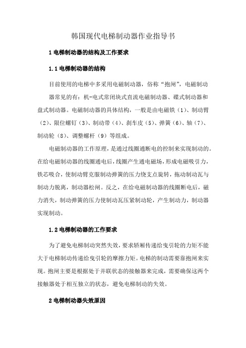
韩国现代电梯制动器作业指导书1电梯制动器的结构及工作要求1.1电梯制动器的结构目前使用的电梯中多采用电磁制动器,俗称“抱闸”,电磁制动器常见的有:机-电式常闭块式直流电磁制动器、碟式制动器和盘式制动器。
电磁制动器的具体结构,一般是由电磁铁(1)、制动臂(2)、限位螺钉(3)、制动带(4)、刹车皮(5)、弹簧(6)、轴(7)、制动轮(8)、调整螺杆(9)等组成。
电磁制动器的工作原理,是通过线圈通断电的控制来实现制动的。
在给电磁制动器的线圈通电后,线圈产生通电磁场,形成电磁吸引力,铁芯吸合,使制动臂克服制动弹簧的压力绕支点旋转,拖动制动瓦与制动力脱离,制动器松闸。
反之,在给电磁制动器的线圈断电后,磁力消失,制动弹簧的压力使制动瓦压紧制动轮,产生制动力,制动器实现制动。
1.2电梯制动器的工作要求为了避免电梯制动突然失效,要求轿厢传递给曳引轮的力矩不能大于电梯制动传递给曳引轮的摩擦力矩。
电梯的制动需要靠抱闸来实现。
抱闸主要是根据处于并联状态的接触器来完成,需要确保这两个接触器处于相互独立的状态,避免电梯制动的失效。
2电梯制动器失效原因2.1机械原因由于清洁不到位,导致异物进入制动器结构中造成机械卡组。
对铁芯、轴活动部件不能做到及时清洁或清洁不到位,导致零部件进入异物,造成设备的卡组现象。
在制动器断电后,不能及时合闸或者根本不能合闸,使制动器启动受阻。
在长期使用中,制动器零部件的腐蚀、折损、老化等也会影响电梯的使用性能。
电磁制动器内线圈表面的绝缘脂老化后,会与电磁铁芯粘连,导致电磁铁芯正常工作受阻或制动力不足,尤其是在电梯开门区域开门瞬间,制动器不能有效工作,引起事故的发生。
制动轮和制动闸瓦的之间磨损严重,导致接触面积降低,影响摩擦效果,摩擦力不足,降低制动效果。
在机械部件涂抹润滑油,有利于设备快速运转。
但润滑油较多时,会降低摩擦零部件和制动轮之间的摩擦力,降低制动效果,给电梯的使用埋下安全隐患。
2.2控制电路不合理在电梯进行制动的过程中,采用两个接触器来控制抱闸的开合,但是这存在一些安全隐患。
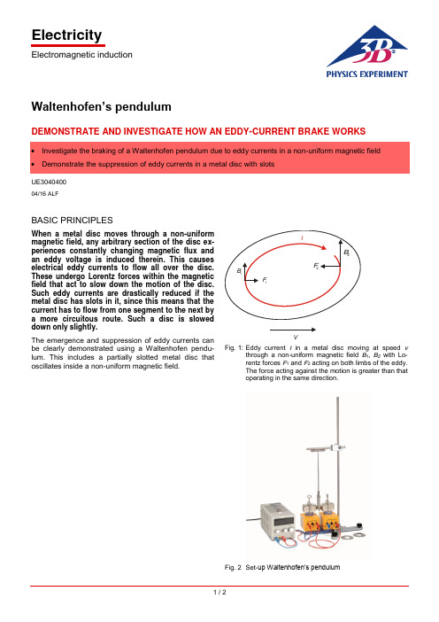
ElectricityElectromagnetic induction1 / 2Waltenhofen’s pendulumDEMONSTRATE AND INVESTIGATE HOW AN EDDY-CURRENT BRAKE WORKSUE304040004/16 ALFBASIC PRINCIPLESWhen a metal disc moves through a non-uniform magnetic field, any arbitrary section of the disc ex-periences constantly changing magnetic flux and an eddy voltage is induced therein. This causes electrical eddy currents to flow all over the disc. These undergo Lorentz forces within the magnetic field that act to slow down the motion of the disc. Such eddy currents are drastically reduced if the metal disc has slots in it, since this means that the current has to flow from one segment to the next by a more circuitous route. Such a disc is slowed down only slightly.The emergence and suppression of eddy currents can be clearly demonstrated using a Waltenhofen pendu-lum. This includes a partially slotted metal disc thatoscillates inside a non-uniform magnetic field.VFig. 1: Eddy current I in a metal disc moving at speed v through anon-uniform magnetic field B 1, B 2 with Lo-rentz forces F 1 and F 2 acting on both limbs of the eddy. The force acting against the motion is greater than that operating in the same direction.Fig. 2 Set-up Waltenhofen’s pendulumUE3040400 3B SCIENTIFIC® PHYSICS EXPERIMENT3B Scientific GmbH, Rudorffweg 8, 21031 Hamburg, Germany, © Copyright 2016 3B Scientific GmbHLIST OF APPARATUS1 Waltenhofen’s pendulum 1000993 (U8497500) 1 Stand base, 150mm 1002835 (U13270) 1 Stand rod, 750mm 1002935 (U15003) 1 Universal clamp1002830 (U13255) 1 Horseshoe magnet 1000979 (U8497215) 1 Pair of pole pieces 1000978 (U8497200) 1 Pair of clamps1000977 (U8497181) 2 Coils with 1200 turns each1000989 (U8497440)1 DC power supply unit 20 V, 5 A @230 V1003312 (U33020-230) or1 DC power supply unit 20 V, 5 A @115 V 1003311 (U33020-115) 1 Set of 15 safety connecting leads 1002843 (U138021)SET-UP∙Set up an electromagnet consisting of a horseshoe magnet, two coils with 1200 windings each and two pole pieces.∙ Connect the coils in series to the DC power supply unit.∙ Firmly attach the aluminium disc to the slotted area inside the pendulum rod.∙Mount the stand rod in the stand base. Use the universal clamp to attach the magnetised rod to the stand rod and suspend the Waltenhofen pendulum from it.∙Arrange the apparatus in such a way that the sec-tion of the aluminium disc without any slots can os-cillate freely between the tips of the pole pieces and the pendulum can come to a state of rest between these pole pieces.∙Select the smallest possible distance between the pole pieces before attaching them, making sure that this does not obstruct the motion of the pendulum.EXPERIMENT PROCEDURE∙ Gradually increase the current passing through the electromagnet in stages.∙ Displace the pendulum from its state of rest and observe its oscillations.∙ Firmly attach the aluminium disc to the area without slots and repeat the procedure.SAMPLE MEASUREMENTSTable 1: Number of oscillations of the aluminium disc in the magnetic field after being deflected from its state of rest. The pole pieces are at a distance of 8mm and the deflection is approx. 7cm.EVALUATIONWhen the side of the metal disc without slots moves through the non-uniform magnetic field, its oscillation is damped. The damping increases with the magnitude of the magnetic field. Eddy currents are induced within the disc and the non-uniform magnetic field exerts a force on the eddy currents that opposes their motion (c.f. Lenz’s Law).If the slotted side of the metal disc moves through the non-uniform magnetic field, the damping of the motion is only slight since it is much more difficult for the eddy currents to form.RESULTSEddy currents are induced in a metal disc which moves within a non-uniform magnetic field. This non-uniform magnetic field exerts a force on the eddy currents that op poses their motion (c.f. Lenz’s Law).In the slotted aluminium disc, it is difficult for eddy cur-rents to form.。

目录1使用要则 (1)1.1符号说明 (1)1.2 维护保养操作前的注意事项 (2)2制动结构 (2)3制动器的维护保养 (3)3.1制动器的维护保养周期 (3)3.2制动器的检测和维护 (3)3.2.1 拆卸制动臂组件 (3)3.2.2 拆卸制动器配件 (4)3.2.3电磁铁内部检测和维护 (4)3.3 制动相关部件的检查和维护 (6)3.3.1 制动臂 (6)3.3.2 制动片和制动轮毂表面的碳化物的清理 (6)3.3.3 闸瓦的更换 (7)4 制动机构的调试 (7)4.1 制动机构的说明 (7)4.2 手动松闸装置 (8)4.3 制动机构的调试 (8)4.3.1闸瓦与制动轮毂间的制动间隙调节 (9)4.3.2 制动力矩的调节 (9)4.3.3 制动间隙的调节 (9)5 制动机构常见故障及排除方法 (10)1 使用要则十分感谢您选用我公司的产品!请注意!不正确的安装、操作或保养都可能使电梯无法正常运行,进而可能导致财产损失或人身伤害!为保证电梯安全、可靠、高质量的运行,在电梯安装、操作、维护保养和使用前,请务必仔细阅读和理解手册的内容,如果在阅读本手册后,对其中的文字内容、表格及图片含义仍然不能完全理解,请您与华升富士达电梯有限公司及时取得联系并获得相应的技术支持。
电梯的安装和维保人员须具备法定的相关资质证书,须经过华升富士达电梯有限公司专业培训和指导。
如安装和维保人员不了解(或熟悉)华升富士达电梯的安装、调试和维护相关知识,请及时联络华升富士达电梯有限公司获得相关信息和指导。
电梯的安装和维保人员作业时应严格遵照本手册的规定,严格遵守国家以及当地的安全、安装和维护规范。
如当地的安全、安装和维护规范与本手册的要求不一致时,请及时联系华升富士达电梯有限公司。
本手册适用于DZS165和DZS200两种型号制动器。
如发现本手册提及产品与实际操作的产品不一致时,请勿擅自安装、操作或维护保养,立即联系华升富士达电梯有限公司获得相关信息和指导。

电机制动器应用须注意的问题Ms.参的朋友售出两台YEJ电机,电机试验时无任何异常,包括对于电机的制动效果验证,但在用户使用时出现电机无法起动的事实。
服务人员到达现场发现,制动器接线出现了问题,重新连接后电机一切正常。
针对于该问题,按照服务人员的意见,对该类电机的出厂接线进行了改进,类似问题没有再出现过。
关于失电制动器电磁制动器是电机常用的附加装置,有通电制动和失电制动两种。
通电制动方式定位快速、精准,用于需精确定位的自动化智能操控设备,应用场合有一定的局限性;电磁失电制动器(以下简称制动器)应用广泛,机床、冶金、电机、化工、建筑、包装印刷、纺织、自动化生产流水线等有定位、刹车要求的机械传动系统普遍采用,除具有操控灵便、制动速度快等优点外,失电制动意味着设备意外停电失控状态下可以安全刹车,确保人身和设施的安全。
结构优势及特点●结构紧凑失电制动器轴向尺寸虽小,但制动扭矩足够大。
●响应迅速失电制动器是采用弹蓄装置形成制动扭矩,弹箭复位时间即为制动响应时间。
●寿命长久失电制动采用新型摩擦材料,决定高寿命的性能。
制动工作原理电磁失电制动器主要由装有线圈的磁扼、衔铁、联结板、弹簧、摩擦盘、齿轮套等零部件组成,弹簧装在磁扼内,衔铁可沿轴向移动。
磁扼由安装螺钉固定在机座上,调整间隙。
至规定值后不动,齿轮套通过键与传动轴相连,齿轮套外齿与摩擦盘内齿啮合。
当线圈断电时,在弹簧力的作用下,摩擦盘与衔铁、机座(或联结板)产生摩擦力,通过齿轮套将传动轴制动,当线圈通电后,在电磁力的作用下,衔铁被吸向磁扼,使摩擦盘松开,解除制动。
制动器工作条件●周围空气相对湿度不大于85%(20±5℃)●周围介质中,无足以腐蚀金属和破坏绝缘的气体及尘埃。
●制动器周围采用B级绝缘,电压波动不超过+5%和-15%的额定电压,其工作方式为连续工作制安装控制要求。
●安装时应保证传动轴部位与制动器的配合精度。
●安装前必须将制动器清洗干净,摩擦面和制动器内部不得有油污和尘埃。

断电式电磁制动器工作原理
断电式电磁制动器是一种常见的机械转动部件制动装置,主要由主体部分、电磁线圈和摩擦体组成。
当电磁继电器通电时,电磁线圈内的铁芯受到磁力吸引,向外推动制动压板,使其离开螺栓孔,制动压板上的制动块便会依靠摩擦力与转子产生阻力,达到制动的目的。
断电时,电磁继电器断电,电磁铁芯失去磁力,制动压板便会被恢复到原来的位置,将制动块与转子分离。
这种制动器具有制动力矩大、响应速度快等特点,常用于机床、起重机械等机械设备中。