J系列说明书Ver
- 格式:docx
- 大小:161.48 KB
- 文档页数:38
智 能 PID 温 度 控 制 仪操 作 说 明 书(Ver0913)南京优倍电气有限公司一、产品概述NPTJ系列智能PID温度控制仪是采用专用微处理器的多功能调节仪表,它采用开关电源和表面贴装技术,因而仪表精致小巧,性能可靠。
特有的自诊断功能、自整定功能和智能控制功能,使操作者可以通过简单的操作而获得良好的效果。
二、主要技术参数输入规格 热电偶:K、S、E、J、T、B、N等热电阻:Pt100、Cu50等测量精度 ±0.5%FS响应时间 ≤0.5秒报警功能 上限、下限、正偏差、负偏差等4种方式报警输出 继电器触点开关输出(常开+常闭),触点容量220V AC/2A或24V DC/2A报警精度 ±1℃或±1定义单位控制输出规格继电器:触点开关输出(常开+常闭),触点容量200V AC/2A或24V DC/2ASSR:驱动电压为12V DC/30mA(用于驱动SSR固态继电器)SCR:单相/三相过零(随机)触发,可触发(5~500)A的双相可控硅、2个单相可控硅反并联连接或可控硅功率模块电压:(0~5)V、(1~5)V电流:(0~10)mA、(4~20)mA、(0~20)mA等(输入电压≥10V)变送范围 (0~22)mA、(0~10)V DC变送精度 0.3级(±0.3%FS)温度补偿 (0~50)℃数字式温度自动补偿使用环境 环境温度:(0~50)℃相对湿度:≤85%,避免强腐蚀气体供电电源 (85~265)V AC(50Hz/60Hz)绝缘电阻 ≥100MΩ 500V DC(电源、输入、输出与地之间)功耗 ≤10W三、仪表面板及操作说明1、仪表面板说明① OUT输出指示灯② RUN手动运行状态指示灯③ PV测量值显示窗口④ SV设定值显示窗口⑤ 设定键----------SET⑥ 移位键----------⑦ 数据减少键------⑧ 数据增加键------△⑨ SP1报警指示灯⑩ SP2报警指示灯2、仪表端子接线四、输入信号方式及类型1、配用标准热电偶、热电阻分度号 分辨率℃ 测量范围℃ 配用传感器 K 1 0~1300 镍铬-镍硅热电偶S 1 0~1600 铂铑10-铂热电偶WRe 1 0~2300 钨铼3~25热电偶T 1 -200~+350 铜-铜镍(康铜)E 1 0~1000 镍铬-铜镍热电偶J 1 0~1000 铁-铜镍(康铜)B 1 600~1800 铂铑10-铂铑6热电偶N 1 0~1300 镍铬硅-镍硅热电偶 Pt100 1 -200~+600 铂热电阻(R0=100Ω) Cu50 0.1 -150~+150 铜热电阻(R0=50Ω)2、输入类型代码表In 输入规格 In 输入规格0 K(-200~+1300)℃ 5 J(0~1000)℃1 S(-50~+1700)℃ 6 B(0~1800)℃2 WRe(0~2300)℃ 7 N(0~1300)℃3 T(-200~+350)℃ 20 Cu50(-50~+150)℃4 E(0~1000)℃ 21 Pt100(-200~+600)℃五、仪表使用和操作1、测量状态仪表安装应进行正确接线,检查无误后上电,仪表自检后进入测量值,显示状态;100300SP2SP1RUN OUTS VPV N EW P WR正确测量状态仪表上电后进入基本显示状态,此时仪表上、下显示窗分别显示测量值(PV)和给定值(SV),显示窗还可交替显示字符表示状态,其中“SP1”、“SP2”、“SPH”或“SPL”时,分别表示发生了上限报警、下限报警、偏差上限报警、偏差下限报警。
用户手册USER’S MANUALXJ9100系列电力网络仪表XJ9100 Series Network Power metersVER2.0许继测控仪表有限公司Xu Ji Measure& Control Meters Co., LtdCopyRight? 2008 XJ9100 Ver2.0Xu Ji Measure & Control Meters Co., Ltd版权所有,未经本公司书面许可,此手册中的任何段落和章节均不得被摘抄、复制与传播。
本公司保留对手册所描述之产品规格修改的权利,恕不另行通知,订货之前,欢迎垂询以确定最新订货信息。
本手册不适用于未受训者,维护、安装工作只由有资质的人完成。
目录一、产品简介....................................................................二、技术参数................................................... 错误!未定义书签。
三、安装........................................................................3.1产品外形尺寸和安装方法.....................................................3.2接线.......................................................................3.2.1 后接线端子图..........................................................3.2.2 端子说明..............................................................3.3接线图 .....................................................................3.4辅助电源 ...................................................................3.5输入信号 ...................................................................四、操作与使用..................................................................4.1屏幕显示说明...............................................................4.1.1屏幕全部显示图..........................................................4.1.2显示字符说明............................................................4.1.3 按键定义..............................................................4.1.4 仪表具体页面...........................................................4.2参数设置 ...................................................................五、通信和输出..................................................................5.1通信协议 (11)5.2通讯应用格式说明 ...........................................................5.3读继电器输出状态(功能码01)...............................................5.4读数字输入状态(功能码02).................................................5.5读数据(功能码03).........................................................5.6控制继电器输出(功能码05)................................................5.7预置多寄存器(功能码16)...................................................5.8XJ9100系列通讯地址表......................................................六、产品选型....................................................................6.1产品命名方法...............................................................6.2快速选型指南...............................................................七、订货说明....................................................................7.1订货举例....................................................................7.2联系我们 (20)一、产品简介XJ9100系列多功能电力仪表采用最现代的微处理器和数字信号处理技术设计而成。


V J系列简明操作手册一、安装与设置打印机关于如何正确安装MUTOH VJ系列户内外写真机(1)由于日本武藤工厂在每一台VJ机器出厂前都要先注墨测试,然后清洗干净。
因此为了防止金彩墨水与原厂墨发生反应,必须在新机注墨前用金彩VJ 专用墨水的清洗液对机器进行两次清洗,清洗后才可以注墨。
这样可以保证机器注墨后稳定的工作。
(2)如果室外温度比较寒冷,在机器运输及停放的过程中机器温度会很低,因此在清洗及注墨前要把机器放置在温暖的房屋中(20-30℃)3个小时以上,同时清洗液及墨水也要先预热(40-60℃)3小时以上或放置在温暖的房屋中(20-30℃)12小时以上。
然后再进行清洗注墨。
1.打印机的安装环境VJ系列为新一代环保弱溶剂写真机,其工作的最佳温度为22℃~30℃,最佳湿度为40%~60%。
安装该机时请注意:1.1 不要将机器放置在以下地点:(1)不牢固的表面(2)倾斜的地方(3)可能由其它的机器引起震动、及电磁干扰的地方(4)潮湿或多尘的地方(5)电话线或照明线路的接地端1.2 不要站立或放置重物在打印机上,不要倾斜打印机或靠墙而立,更不允许上下颠倒放置,不要用布遮住打印机的通风口,不要使用受损的电缆,不要用潮湿的手去拨插电源插头。
1.3清洁打印机之前请先关闭电源并断开连接电缆,运输过程中请将打印机保持水平。
1.4 电源插座使用含有地线端子的插座,此外,最好在机器的金属外壳上再单独接一根地线。
地线应采用含有铜的电缆并置入地下不少于650mm的地方。
2.设置打印机2.1操作面板说明图1.VJ系列操作面板a)显示屏VJ系列使用单行显示屏,待机状态时显示为“Ready to Print”,打印时显示“Printing”,报错时会显示错误代码及英文报错信息(请记下)。
b)指示灯VJ系列的指示灯主要有:Power为电源指示灯,同时也是电源按键。
开机后,电源灯亮。
当其长亮时,表示机器正常运行;当其闪烁时,表示有错误发生,此时,显示屏会显示错误代码及英文报错信息,请记录此信息,以便告知工程师。

XJPMF910J微机电压互感器监测装置技术及使用说明书(Ver1.00)许继智能控制技术有限公司XJ INTELLIGENT CONTROL TECHNOLOGY CO.,LTD.XJPMF910J微机电压互感器监测装置应用范围适用于35kV及以下电压等级的电压互感器的保护及测控。
装置硬件后插拔方式,强弱电分离;加强型单元机箱按抗强振动、强干扰设计,可分散安装于开关柜上运行。
采用32位高性能SoC嵌入式微机处理器,大容量的RAM和Flash Memory;数据处理、逻辑运算和信息存储能力强,运行速度快,可靠性高。
高精度AD采样,测量精度高。
可保存不少于80个最近发生的事件报告及运行报告。
采用图形液晶,中文显示,菜单式操作。
双RS-485接口主要特点实时多任务操作系统,模块化编程;实时性好,可靠性高。
8套保护定值,定值区切换安全方便。
标准通信规约,方便与微机监控或保护管理机联网通讯。
设置遥控并列、解列功能。
保护与测控一体化,单台装置完成间隔主要功能。
我公司保留对本说明书进行修改的权利;产品与说明书不符时,请参照实际产品说明。
目录1 装置简介 (1)1.2 主要特点 (1)2 技术指标 (1)2.1 额定数据 (1)2.2 装置功耗 (2)2.3 环境条件 (2)2.4 抗干扰性能 (2)2.5 绝缘性能 (3)2.6 机械性能 (3)2.7 保护定值整定范围及误差 (3)2.8 测量精度 (4)2.9 触点容量 (4)3 装置硬件 (4)3.1 机箱结构 (4)3.2 主要插件 (5)3.3 交流插件 (5)3.4 CPU插件 (5)3.5 信号插件 (5)3.6 人机对话界面 (5)3.7通讯 (5)4 保护功能 (5)4.1 过电压保护 (5)4.2 低电压保护 (6)4.3 接地保护 (6)4.4 TV自动并列 (7)4.5 手动TV并列/解列 (7)4.6 TV断线告警 (7)4.7 装置故障告警 (7)4.8 遥信、遥控、遥脉及遥测功能 (7)5 辅助功能 (8)5.1 录波 (8)5.2 GPS对时 (8)6 装置使用说明 (8)6.1 压板整定信息 (8)6.2 定值整定信息 (8)6.3 动作信息及说明 (9)6.4 出口配置说明 (10)6.5 人机界面操作说明 (10)7 投运说明及注意事项 (15)8 IEC60870-5-103规约点表 (15)8.1 保护动作故障信号 (15)8.2 告警信号 (16)8.3 状态信号 (16)8.4 控制 (17)8.5 遥测 (17)8.6 电度 (17)8.7 总召唤信息 (17)8.8 录波 (17)9 贮存及保修 (18)9.1 贮存条件 (18)9.2 保修时间 (18)10 供应成套性 (18)10.1 随同产品一起供应的文件 (18)10.2 随同产品一起供应的附件 (18)11 订货须知 (19)12 附图 (19)1 装置简介XJPMF910J微机电压互感器监测装置(以下简称装置),主要应用于35k V及以下电压等级的单母分段方式。
在安装、感谢您选购本产品!为了保证安全并获得最佳效能,使用产品前,请务必详细阅读本使用说明书并妥善保管,以备今后参考。
矿用激光甲烷传感器GJG100J使用说明书GB 3836-2010执行标准:AQ 6211-2008Q/NCS015-2016司限公有创宁波盛仪表LTD.﹒,NINGBO TRUNSUN INSTRUMENT CO320161115 防爆合格证号:安标编号:MFB170040: 2016.08.15颁布日期VER1.1 版本号:警告:本传感器检修时不得改变本安电路和本安电路有关的元器件的电气参数、规格和型号,本安产品不得随意与其他未经联检的设备连接。
在井下或危险场所采样过程中,严禁打开机盖,出现故障应返回地面请专职人员维修。
1矿用激光甲烷传感器GJG100J概述一产品特点、主要用途及使用范围1.1采用光谱吸收原理测量甲烷气(以下简称传感器)GJG00J矿用激光甲烷传感器体浓度,测量精确,工作稳定,无需用户校准,可长期在线工作。
传感器输出标准数字信号,可以与监控分站等其它控制器联机使用,适用于煤RS485的频率信号或矿井下有瓦斯、煤尘爆炸危险的环境。
使用环境条件1.240℃;a) 环境温度:0℃~+ 25℃); b) 平均相对湿度:不大于95%(+ 116kPa;大气压力:80kPa~ c)d) 无显著振动和冲击的场合;煤矿井下有甲烷、煤尘爆炸性混合物,但无破坏绝缘的腐蚀性气体的混合气 e) 体。
A.11.3 关联设备见附录:1.4 防爆型式。
ExiaⅠMa矿用本质安全型,防爆标志:型号及命名1.5J100 G G J激光原理)CH测量范围:(0%~100%4光学原理甲烷传感器二结构特征、工作原理、接线示意图2.1结构特征传感器采用密封结构的不锈钢壳体,在壳体侧面和底面分别设有电缆接口和测 2量进气口,壳体顶部设有报警灯。
壳体上部留有悬挂把手,安装方便。
2.2 工作原理传感器由激光测量探头、信号处理电路,主控制器,电源调理电路,信号输出电路等组成。
Surface protecitive materials for plastic nameplatesSPV-J SeriesSPV-J-200/J-300/J-400/J-500OutlineSPV-J Series is surface protective materials using polyolefin film.These products are suitable for printing, punching and transportation of plastic nameplates. ConstructionNatural rubber pressure sensitive adhesivePolyolefin filmWax base release coatingFeatures-Minimal change in adhesive strength after laminating enables to be easy peeling.-Depending on the surface roughness and degree of processing, the most suitable product among a wide range of adhesive strength products can be used.-Offers excellent initial adhesion and easy application. Film can be easily peeled and re-applied (manual application) when inspecting printed surfaces.-Suitable for namplate punching and molding proscesses.ApplicationsSurface protection for printing, punching and transportaion of plastic nameplates.SPV-J Series_E1/3Standard Size/ColorItem Thickness (mm) Width (mm) Length (M) Color SPV-J-200 0.045 1250 200 ClearSPV-J-300 0.045 1250 200 ClearSPV-J-400 0.045 1250 200 ClearSPV-J-500 0.045 1250 200 Clear*Contact us for information concerning sizes.General propertiesItem Unit SPV-J-200 SPV-J-300 SPV-J-400 SPV-J-500 Thickness *1 mm 0.045 0.045 0.045 0.045 Adhesive Strength *2 N/20mm 0.25 0.45 0.90 1.20 Tensile Strength *3 N/20mm 35 35 35 35 Elongation *3 %500 500 500 500Test Method*1:Nominal thickness*2:Adherend SUS430BA,Tensile speed 300mm/min,Peeling angle 90deg.,Dwell time20-40min.*3:Tensile speed 300mm/min, strength and elongation when breakingSPV-J Series_E2/3Precautions-Duly inspect the adaptability of this product to your intended use, prior to its application.We may conduct the adaptability test in your favor. However, its content and results do not guarantee your use. It is of your responsibility to ultimately determine its adaptability.-The characteristics and performance of this product depends on the type of adherend, environment of use, and conditions/period after application. Always test (including the appearance) before changing the adherend (composition/surface roughness), conditions or use.-When the product is applied to PVC adherends with plasticizer or surface-active adherends (electrolyzed, chemically treated, polished, etc.), it may become difficult to release or may tend to leave deposits, as time passes.-When applying the product to a display material, test with particular attention on appearance defects. Stain, cloudiness or unevenness may appear on the surface of the display material, depending on its type. Traces of air bubbles may be left if they are trapped during application.-Aforementioned problems may also arise when the product is stored for a long period of time after application.-Do not ues the product outdoors.-Remove any grease, moisture or dust on the adherend before application.-When coating after the surface protective material has been peeled, products should be used upon giving sufficient consideration to surface washing, below-surface processing and sintering conditions and confirming the adhesiveness of the coating.SPV-J Series_E3/3。

J-SeriesRefrigerators & Freezers Installation and Operation Manual Please read this manual completely before attempting to install or operate this equipment!SOLID DUAL TEMPERATUREJRF-19 JRF-45JRF-65BUFFET DISPLAY TABLESJBT-36 JBT-48JBT-60 JBT-72SANDWICH / SALAD UNITSS T-48S T-36 JJS T-72S T-60 JJUNDERCOUNTERREFRIGERATORS / FREEZERSJUR-36 JUF-36JUR-48 JUF-48JUR-60 JUF-60JUR-72JUR-48-G JURF-48JUR-60-G JURF-60JUR-72-G JURF-72SERIAL NUMBER2 PART NAME AND FUNCTIONUP-RIGHTSALAD/UNDERCOUNTER3-4 5-7 8-1112 13 13 14CAUTIONINSTALLATION AND OPERATION INSTALLATION NOTECLEANING TROUBLESHOOTINGPRECAUTIONS• The Serial number is located on the data label inside • Please retain the unit’s serial number for service purpose 15-17WARRANTYTOP MOUNT(REFRIGERATOR, FREEZER)1. FRAMEWORK• To maintain proper refrigeration performance the condenser coilmust be free of dust, dirt, and grease• This will require periodic cleaning. Condenser fins should be cleaned at least every three months(90days)If the product is abnormal in the course of use, check it as follows, if youcan not solve the problem, please contact the after sale service, and provide product information (such as model, serial number etc.)SYMPTOMSCHECK AND SOLUTIONS 1.The unit does not refrigerate at all • Check that the power cord andplug in correctly• Be sure the power cord is connectedto the proper voltage• Be sure the power switch is turned on• Be sure the temp setting is on thecorrect position• Check the partition of stored food• The unit door is opened too frequentlyor left open too long• Be sure the unit is away from heater• The condenser isn’t clean for a longtime• The floor is uneven or the caster isn’tset correctly• Be sure the unit is away from anyother objects• Be sure nothing fall into the condensingunit• The smelled food isn’t completelycovered• Be sure the food is under guarantee• The unit isn’t clean for a long time2.The unit does not refrigerate well3.There is loud noise4. There is peculiar smellMANUFACTURING COMP ANYTurbo Air warrants to the original purchaser of every new Turbo Air refrigerated unit, the cabinet and all parts thereof, to be free from defects in material or workmanship, under normal use and service, for a period of two (2) year from the date of original installation or 27 months after shipment date from Turbo Air , whichever occurs first.Any parts covered by this warranty that are examined and determined by Turbo Air to have been defective within two (2) year of original installation or twenty seven (27) months after shipment date from manufacturer, whichever occurs first, shall be repaired or replaced as stated below. Turbo Air shall be deemed to have fully complied with its obligation under the foregoing warranties by electing either one of the following procedures, at the sole discretion of Turbo Air.1. Furnishing a replacement part, freight collect, in even exchange for the returned part, freight collect.2. Receiving the defective part, freight collect; repairing it; and returning it, freight collect.In addition to the (2) two year warranty stated above, Turbo Air warrants its hermetically and semi-hermetically sealed compressor to be free from defects in both material and workmanship under normal use and service for a period of three (3) additional years from the date of original installation but not to exceed five (5) years and three (3) months after shipment fr om manufacturer.Compressors determined by Turbo Air have been defective within this extended time period will, at Turbo Airʼs option, be either repaired or replaced with a compressor or compressor parts of similar design and capacity.The three (3) year extended compressor warranty applies only to hermetically and semi-hermetically sealed parts of the compressor and does not apply to any other parts or components, including, but not limited to, cabinet, paint finish, temperatu re control, refrigerant, metering device, driers, motor starting equipment, fan assembly any other electrical component, etcetera.The five year compressor warranty detailed above will be voided if the following procedure is not carefully adhered to:1. This system contains R134A refrigerant and polyol ester lubricant. The Polyol ester lubricant has rapid moisture absorbing qualities. If long exposure to the ambient conditions occur, the lubricant must be removed and replaced with new. Listed below are the approved lubricants for the Tecumseh compressors.1 ICI-Emkarate RL 1842 Emery-2927-A3 Mobile Artic 22AFailure to comply with recommended lubricant specification will void the compressor warranty.2. Dryer replacement is very important and must be changed when a system is opened for servicing. dryer must be used with XH-9 desiccant.3. Micron level vacuums must be achieved to insure low moisture levels in the system. 500 microns or lower must obtained.Turbo Airʼs sole obligation under this warranty is limited to either repair or replacement of parts, subject to the additional limitations below. This warranty neither assumes nor authorizes any person to assume obligations other than expressly covered b y this warranty.1. WARRANTY IS NOT TRANSFERABLE. This warranty is not assignable and applies only in favor of the originalpurchaser/user to whom delivered. ANY SUCH ASSIGNMENT OR TRANSFER SHALL VOID THE WARRANTIES HEREIN MADE AND SHALL VOID ALL WARRANTIES, EXPRESS OR IMPLIED, INCLUDING ANY WARRANTY OF MERCHANTABILITY OR FITNESS FOR A PARTICULAR PURPOSE.2. NO CONSEQUENTIAL DAMAGES. TURBO AIR IS NOT RESPONSIBLE FOR ECONOMIC LOSS; PROFIT LOSS ORSPECIAL, INDIRECT, OR CONSEQUENTIAL DAMAGES, INCLUDING WITHOUT LIMITATION, LOSSES OR DAMAGES ARISING FROM FOOD OR PRODUCT SPOILAGE CLAIMS WHETHER OR NOT ON ACCOUNT OF REFRIGERATION FAILURE.3. ALTERATION, NEGLECT, ABUSE, MISUSE, ACCIDENT, DAMAGE DURING TRANSIT OR INSTALLATION, FIRE,FLOOD, ACTS OF GOD. TURBO AIR is not responsible for the repair or replacement of any parts that Turbo Air determines have been subjected after the date of manufacture to alteration, neglect, abuse, misuse, accident, damage during transit or installation, fire, flood, or an Act of God.4. NO IMPLIED WARRANTY OF MERCHANTABILITY OR FITNESS FOR A PARTICULAR PURPOSE. THERE ARE NOOTHER WARRANTIES, EXPRESS, IMPLIED OR STATUTORY, EXCEPT THE TWO(2) YEAR WARRANTY AND THE ADDITIONAL THREE (3) YEAR COMPRESSOR WARRANTY AS DESCRIBED ABOVE. THESE WARRANTIES ARE EXCLUSIVE AND IN LIEU OF ALL OTHER WARRANTIES, INCLUDING IMPLIED WARRANTY AND MERCHANTABILITY OR FITNESS FOR A PARTICULAR PURPOSE. THERE ARE NO WARRANTIES WHICH EXTEND BEYOND THE DESCRIPTION ON THE FACE HEREOF.5. TRANSPORTATION COSTS. Turbo Air will accept parts covered under this warranty freight collect, provided that shipmenthas received prior approval. Turbo Air is not responsible for any other transporation costs, but will ship freight collect part s either repaired or replaced under these warranties.6. WARRANTY CLAIMS. All claims should include: model number of the cooler, the serial number of the cabinet, proof ofpurchase, date of installation, and all pertinent information supporting the existence of the alleged defect. Any action or bre ach of these warranty provisions must be commenced within two (2) year after that cause of action has accrued.4184 E. Conant St.Long Beach, CA 90808TEL : 310-900-1000FAX : 310-900-1077TOLL FREE : 1-800-627-0032(U.S.A. & Canada)Website : Warranty Claims...All claims for parts or labor must be made directly thorough Turbo Air.All claims should include: model number of the unit, the serial number of the cabinet, proof of purchase, date of installation, and all pertinent information supporting the alleged defect.In case of compressor replacement under warranty, either compressor or compressor tag must be returned to Turbo Air along withabove listed information.Failure to comply with warranty policies will result in voiding claims.Two Year Parts & Labor Warranty...Turbo Air warrants all new refrigerated components, the cabinet and all parts, to be free from defects in materials or workmanship,under normal and proper use and maintenance service as specified by Turbo Air and upon proper installation and start-up inaccordance with the instruction packet supplied with each Turbo air unit. Turbo Airʼs obligation under this warranty is limited to a periodof two (2) year from the date of original installation or 27 months after shipment date from Turbo Air, whichever occurs first.Any part, covered under this warranty, that are by Turbo Air to have been defective within two (2) year of original installation or twenty seven (27) months after shipment date from manufacturer, whichever occurs first, is limited to the repair or replacement, including labor charges, of defective parts or assemblies. The labor warranty shall include standard straight time labor charges only and reasonabletravel time, as determined by Turbo Air.Additional Three Year Compressor Warranty...In addition to the two (2) year warranty stated adove, Turbo Air warrants its hermetically sealed compressor to be free from defects inboth material and workmanship under normal and proper use and maintenance service for a period of three (3) additional years fromthe date of original installation, but not to exceed five (5) years and three(3) months after shipment from the manufacturer.Compressor determined by Turbo Air to have been defective within this extended period will, at Turbo Airʼs discretion, be eitherrepaired or replaced with a compressor or compressor parts of similar design and capacity.The three (3) year extended compressor warranty applies only to hermetically sealed parts of the compressor and does not apply to any other parts or components, including, but not limited to, cabinet, paint finish, temperature control, refrigerant, metering device, driers,motor starting equipment, fan assembly or and other electrical components, etcetera.404A / 134a Compressor Warranty...The five-year compressor warranty detailed above will be void if the following procedure is not carefully adhered to:1. This system contains R404A or R134a refrigerant and polyol ester lubricant. The polyol ester lubricant has rapid moisture absorbingqualities.2. Drier replacement is very important and must be changed when a system is opened for servicing. A620 copper drier or better ishighly recommended.3. Micron level vacuums must be achieved to insure low moisture levels in the system. 500 microns or lower must be obtained.4. When compressor is grounded, suction drier and 620 drier or better must be replaced.5. Compressor must be obtained through Turbo Air, unless otherwise specified in writing, through Turbo Airʼs warranty department.404A / 134a Compressor Warranty...Turbo Airʼs sole obligation under this warranty is limited to either repair or replacement of parts, subject to the additional limitationsbelow. This warranty neither assumes nor authorizes any person to assume obligations other than those expressly covered by this warranty.NO CONSEQUENTIAL DAMAGES. TURBO AIR IS NOT RESPONSIBLE FOR ECONOMIC LOSS; PROFIT LOSS; OR SPECIAL, INDIRECT, OR CONSEQUENTIAL DAMAGES, INCLUDING WITHOUT LIMITATION, LOSSES, OR DAMAGES ARISING FROMFOOD OR PRODUCT SPOILAGE REGARDLESS OF WHETHER OR NOT THEY RESULT FROM REFRIGERATION FAILURE. WARRANTY IS NOT TRANSFERABLE, This warranty is not assignable and applies only in favor of the original purchaser/user towhom delivered. ANY SUCH ASSIGNMENT OR TRANSFER SHALL VOID THE WARRANNTIES HEREIN AND SHALL VOID ALL WARRANTIES, EXPRESS OR IMPLIED, INCLUDING ANY WARRANTY OF MERCHANTABILITY OR LABOR COVERAGE FOR COMPONENT FAILURE OR OTHER THE WARRANTY PACKET PROVIDED WITH THE UNIT.ALTERATION, NEGLECT, ABUSE, MISUSE, ACCIDENT, DAMAGE DURING TRANSIT OR INSTALLATION, FIRE, FOOD, ACTSOF GOD. Turbo Air is not responsible for the repair or replacement of any parts that Turbo Air determines have been subjected afterthe date of manufacture to alteration, neglect, abuse, misuse, accident, damage during transit or installation, fire, flood, or act of GOD. IMPROPER ELECTRICAL CONNECTIONS. TURBO AIR IS NOT RESPONSIBLE FOR THE REPAIR OR REPLACEMENT OFFAILED OR DAMAGED COMPONENTS RESULTING FROM ELECTRICAL POWER FAILURE, THE USE OF EXTENSION CORDS,LOW VOLTAGE, OR VOLTAGE DROPS TO THE UNIT. NO IMPLIED WARRANTY OF MERCHANTABILITY OR FITNESS FOR A PARTICULAR PURPOSE; THERE ARE NO OTHER WARRANTIES, EXPRESSED, IMPLIED OR STATUTORY, EXCEPT THE TWO(2) YEAR PARTS & LABOR WARRANTY AND THE ADDITIONAL THREE (3) YEAR COMPRESSOR WARRANTY AS DESCRIBED ABOVE. THESE WARRANTIES ARE EXCLUSIVE AND IN LIEU OF ALL OTHER WARRANTIES, INCLUDING IMPLIED WARRANTY AND MERCHANTABILITY OR FITNESS FOR A PARTICULAR PURPOSE. THERE ARE NO WARRANTIES, WHICH EXTENDBEYOND THE DESCRIPTION ON THE FACE HEREOF.Outside U.S.and Canada; This warranty does not apply to, and Turbo Air is not responsible for, any warranty claims made on productssold or used outside the continent of the United States and Canada.New Extended Warranty policy applies to all units sold by Turbo Air starting Dec.1, 2012。

安装、使用产品前,请阅读安装使用说明书一、J-SAM-GST9121C手动火灾报警按钮安装使用说明书(Ver.1.01,2021.08)注意事项产品仅应被安装在产品安装使用说明书所明示规定的使用环境,不适用于有易燃性物质、有爆炸性物质或有腐蚀性物质的场所(包括使用磷化铝杀虫剂的烟草仓库)。
产品不可被安装在对设备有特殊认证要求的环境或场所(包括但不限于爆炸性环境、船舶、飞机、火车、机动车等交通工具)。
如有特殊需求,请联系本公司相应销售人员。
二、概述J-SAM-GST9121C手动火灾报警按钮(以下简称报警按钮)安装在公共场所,当人工确认火灾发生后按下报警按钮上的按片,可向控制器发出火灾报警信号,控制器接收到报警信号后,显示出报警按钮的编码信息并发出报警声响。
三、特点1.新型插拔式卡接结构,安装、拆卸简单方便,按片在按下后可用专用工具复位。
2.报警按钮动作机构采用专利设计,抗灰尘能力强。
3.采用32位ARM微处理器实现信号处理,用数字信号与控制器进行通信,工作稳定可靠,对电磁干扰有良好的抑制能力。
4.地址码为电子编码,可现场改写。
四、技术特性1.工作电压:信号总线电压:24V 允许范围:16V~28V2.工作电流:监视电流≤0.3mA报警电流≤0.9mA3.启动零件型式:可重复使用型4.启动方式:人工按下按片5.复位方式:用专用钥匙复位6.指示灯:红色,正常巡检时约3s闪亮一次,报警后点亮7.编码方式:电子编码,编码范围在1~242之间任意设定8.线制:与控制器无极性二线制连接9.使用环境:类型:户内温度:-10℃~+55℃相对湿度≤95%,不凝露10.外形尺寸:91mm×91mm×45.5mm (带底壳)11.外壳防护等级:IP4012.壳体材料和颜色:ABS,红色13.重量:约123g(含底壳)14.安装孔距:60mm五、结构特征与工作原理1. 报警按钮的外形示意图如图1所示。
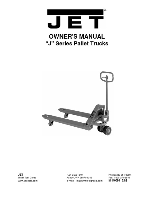
OWNER'S MANUAL“J” Series Pallet TrucksJET P.O. BOX 1349 Phone:253-351-6000 WMH Tool Group Auburn, WA 98071-1349 Fax: 1-800-274-6840 **************************M-140080 7/02This manual has been prepared for the owner and operators of a JET “J” Series Pallet Truck. Its purpose, aside from tool operation, is to promote safety through the use of accepted correct operating and maintenance procedures. Completely read the safety and maintenance instructions before operating or servicing the tool. To obtain maximum life and efficiency from your pallet truck, and to aid in using the tool safely, read this manual thoroughly and follow instructions carefully.Warranty & ServiceThe WMH Tool Group warrants every product it sells. If one of our tools needs service or repair, one of our Authorized Repair Stations located throughout the United States can give you quick service.In most cases, any one of these WMH Tool Group Repair Stations can authorize warranty repair, assist you in obtaining parts, or perform routine maintenance and major repair on your JET, Performax, Powermatic or Wilton tools.For the name of an Authorized Repair Station in your area, please call 1-800-274-6848.More InformationRemember, the WMH Tool Group is consistently adding new products to the line. For complete, up-to-date product information, check with your local WMH Tool Group distributor.WMH Tool Group WarrantyThe WMH Tool Group (including JET, Performax, Powermatic and Wilton brands) makes every effort to assure that its products meet high quality and durability standards and warrants to the original retail consumer/purchaser of our products that each product be free from defects in materials and workmanship as follow: 1 YEAR LIMITED WARRANTY ON ALL PRODUCTS UNLESS SPECIFIED OTHERWISE. This Warranty does not apply to defects due directly or indirectly to misuse, abuse, negligence or accidents, normal wear-and-tear, repair or alterations outside our facilities, or to a lack of maintenance.THE WMH TOOL GROUP LIMITS ALL IMPLIED WARRANTIES TO THE PERIOD SPECIFIED ABOVE, FROM THE DATE THE PRODUCT WAS PURCHASED AT RETAIL. EXCEPT AS STATED HEREIN, ANY IMPLIED WARRANTIES OR MERCHANTIBILITY AND FITNESS ARE EXCLUDED. SOME STATES DO NOTALLOW LIMITATIONS ON HOW LONG THE IMPLIED WARRANTY LASTS, SO THE ABOVE LIMITATION MAY NOT APPLY TO YOU. THE WMH TOOL GROUP SHALL IN NO EVENT BE LIABLE FOR DEATH, INJURIES TO PERSONS OR PROPERTY, OR FOR INCIDENTAL, CONTINGENT, SPECIAL, OR CONSEQUENTIAL DAMAGES ARISING FROM THE USE OF OUR PRODUCTS. SOME STATES DO NOT ALLOW THE EXCLUSION OR LIMITATION OF INCIDENTAL OR CONSEQUENTIAL DAMAGES, SO THE ABOVE LIMITATION OR EXCLUSION MAY NOT APPLY TO YOU.To take advantage of this warranty, the product or part must be returned for examination, postage prepaid, to an Authorized Repair Station designated by our office. Proof of purchase date and an explanation of the complaint must accompany the merchandise. If our inspection discloses a defect, we will either repair or replace the product, or refund the purchase price if we cannot readily and quickly provide a repair or replacement, if you are willing to accept a refund. We will return repaired product or replacement at WMH's expense, but if it is determined there is no defect, or that the defect resulted from causes not within the scope of WMH's warranty, then the user must bear the cost of storing and returning the product. This warranty gives you specific legal rights; you may also have other rights which vary from state to state.The WMH Tool Group sells through distributors only. Members of the WMH Tool Group reserve the right to effect at any time, without prior notice, those alterations to parts, fittings, and accessory equipment which they may deem necessary for any reason whatsoever.WARNING• Read and understand the entire owner’s manual before using the pallet truck.• Do not place hands or feet under the pallet truck at any time.• Do not operate a loaded pallet truck on ramps, or inclines.• Do not tip load pallet truck forks. This may cause damage to the forks and personal injury if the rear of the pallet truck suddenly "pops up".• Never leave a loaded pallet truck unattended in the raised position. Always lower load to the floor. • Do not load pallet truck beyond its rated capacity 5,000 lbs.• Secure load before transporting.• To prevent accidental tipping, make sure load is centered on the forks.• Do not move a loaded pallet truck by other than manual force.• Failure to comply with these warnings may result in personal injury and/or property damage. IntroductionCongratulations on your purchase of a JET Pallet Truck.To better understand the proper use and safe operation of this pallet truck, please take a few minutes to carefully read and follow the instructions contained in this manual. When finished reading and understanding the manual, please file in a safe and convenient location for the life of the pallet truck.This pallet truck is designed to push and pull palletized material loads up to 5,000 pounds only.You will notice several important features about your JET Pallet Truck. One, its 2-1/2” lowered height and tapered fork tips allow easy entry into pallets. The PT-3348J four-way pallet truck features a 2” lowered height.The heavy-gauge steel frame is reinforced with cross-welded steel plates to prevent forks from bending and solid steel push rods are used for added strength. The pump features top-of-the-stroke and overload by-pass valve systems. A durable powder coat finish provides long lasting steel protection.Extra wide polyurethane covered steel steer wheels and nylon load wheels feature lifetime lubricated, double sealed bearings to provide smooth, quiet rolling and added stability.Your JET Pallet Truck is truly one of the finest pallet trucks in the world.Record Your Purchase Information HerePurchased from: Date:Model Number: Stock Number:Serial Number: Date in Service:Table of ContentsWarranty .................................................................................................................................................2 Warnings.................................................................................................................................................3 Introduction..............................................................................................................................................3 Purchase Information...............................................................................................................................3 Table of Contents....................................................................................................................................4 Specifications..........................................................................................................................................4 Assembly..............................................................................................................................................5-6 Pallet Truck Operation..........................................................................................................................6-7 Up-Down Cam Adjustment.......................................................................................................................7 Bleed the Pump.......................................................................................................................................7 Lubrication...............................................................................................................................................7 Seal and O-Ring Replacement ................................................................................................................8 Troubleshooting.......................................................................................................................................9 Parts Breakdown & Parts List............................................................................................................10-13 Test Certificate.. (14)SpecificationsThe specifications in this manual are given as general information and are not binding. JET Equipment & Tools reserves the right to effect, at any time and without prior notice, changes or alterations to parts, fittings, and accessory equipment deemed necessary for any reason whatsoever. Model #Stock #W1W2L1L2H1H2 A (dxw) B (dxw) CNet Wt. lbs.PT-1636J14001616”6”36”51”6-1/4”2-1/2” 6-1/4”x2-3/4” 2-1/2”x3-3/4” 45-1/8”135PT-2036J 140085 20 1/2” 6” 36” 51” 6-1/4” 2-1/2” 6-1/4”x2-3/4” 2-1/2”x3-3/4” 45-1/8” 150 PT-2042J14008420 1/2”6”42”57”6-1/4”2-1/2” 6-1/4”x2-3/4” 2-1/2”x3-3/4” 45-1/8”161PT-2048J 140083 20 1/2” 6” 48” 63” 6-1/4” 2-1/2” 6-1/4”x2-3/4” 2-1/2”x3-3/4” 45-1/8” 172 PT-2736J14008227” 6”36”51”6-1/4”2-1/2” 6-1/4”x2-3/4” 2-1/2”x3-3/4” 45-1/8”174 PT-2742J 140081 27” 6” 42” 57” 6-1/4” 2-1/2” 6-1/4”x2-3/4” 2-1/2”x3-3/4” 45-1/8” 185 PT-2748J14008027”6”48”63”6-1/4”2-1/2” 6-1/4”x2-3/4” 2-1/2”x3-3/4” 45-1/8”196PT-3348J 140033 33” 6” 48” 63” 6” 2” 6-1/4”x2-3/4” 2”x3-3/4” 45-1/8” 216AssemblyNote: Individual trucks are assembled and ready to use. Pallet trucks purchased in crate quantities (6 units to a crate) require some assembly. Match the “number” label on the handle to the “number” label on the frame, prior to assembly.Tools Needed for Assembly• Hammer• Flat Head Screwdriver• Pliers or 17mm Wrench1. Insert the base of the handle (A, Fig. 1) intothe pump bracket (B, Fig. 1).2. Align the holes (C, Fig. 1) at the base of thehandle with the holes in the pump bracket.3. Using a screwdriver, pry the cam (D, Fig. 1)up and slip the bolt head, under the notch inthe cam. Do not adjust the nut.4. Insert handle pins (E, Fig. 2) into the holesof the pump bracket and handle. Align the spring pin holes (F, Fig. 2) in the handle pinand the pump bracket.5. Tap the handle pins into place with ahammer.6. Using a hammer, tap the spring pins (A, Fig.3) into the pump bracket and handle pins.Note: If the holes aren’t lined up use a 17mm wrench or pliers to turn the handle pin until the spring pin holes line up.7. Repeat for the opposite side handle pin.8. Pull the handle down and remove theretaining bracket (B, Fig. 3) by pulling straight out. Discard retaining bracket. Note: If the pallet truck does not raise, or lower properly you may have air bubbles in the pump from shipping. Refer to “Bleed the Pump” on page 7.Pallet Truck OperationTo raise the forks, place handle in the UP position (bottom part of the handle slot), see Fig. 4.To lower forks, pull lever handle to DOWN position (upper part of the slot).To freely move the handle, set the lever in Neutral (center notch of slot).To Lift a Load1. Lower forks to lowest position, Figure 4.2. Insert forks under load, or into pallet.3. Place lever in UP position (bottom part ofslot), Figure 4.4. Move handle up, and down until forks reachdesired height.To Move a Load1. Place lever in NEUTRAL position (centernotch of slot), Figure 4.2. Pull or push pallet truck to desired location.To Lower a Load1. Pull lever to the DOWN position (upper partof slot), Figure 5.2. Pull forks away from load.Up-Down Cam Adjustment1. Set the lever in the NEUTRAL position,Figure 5.2. Turn the cam nut while pumping the handle,Figure 6.3. When lifting stops, give the nut one moreturn.4. The cam nut is properly adjusted whenpumping the handle in the NEUTRAL position causes no movement of the hydraulic ram.Cleaning the Release Valve (Bleed the Pump)Over time, the hydraulic pump assembly may become clogged with debris, air bubbles, and not function properly.To clean the release valve and bleed the pump: 1. Pump handle quickly, raising pallet truck tofull extent. While continuing pumping action, pull lever to down position.2. When forks reach total down position, valveis flushed. Repeat if necessary. LubricationCheck the oil level annually by removing the oil plug found on the top of the pump housing. When changing or adding oil, fill the tank through the oil plug screw hole to 80% capacity with hydraulic jack oil, about 2” deep in pump housing, see Figure 7. Do not use any other type of oil.There is one grease fitting (#55B in the breakdown) located on the table. Lubricate this point on a semi-annual basis.Wheel bearings are sealed and require no lubrication. Crank Shaft features oil light bushings that also require no lubrication.Lightly oil all moving parts.Seal and O-Ring Replacement for Piston Array and Plunger Piston1. Raise the pallet truck by pumping handle.2. Remove the bolts #70. This will free thepump and handle assembly from the pallet truck.3. Empty the oil into a suitable container.Pump handle until all oil has drained.Dispose of used hydraulic oil, or fluid according to local disposal regulations.4. Pull out piston plunger #33, and/or rampiston #25.5. Remove all o-rings and seals, see Figure 8.6. Insert new o-ring or seal one at a timemaking sure to replace with the same size that was removed.7. Reassemble and fill the oil tank through theoil plug screw hole to 80% capacity with newhydraulic jack oil, about 2” deep in pumphousing, see Figure 7.TroubleshootingCondition ProbableCauses CorrectiveActionHydraulic unit does not lift. 1. Oil low in tank.2. Air in pump.3. Worn O-ring in ram cylinder.1. Make sure there is no oilleakage from Release Plug#36 or Pressure AdjustmentScrew #27, and add oil.2. Place the lever in the downposition and pump thehandle repeatedly.3. Consult authorized repairstation.Once lifted, truck lowers by itself. 1. Steel ball not seated inhydraulic unit.2. Worn O-ring in ram cylinder.3. Release valve not seatedproperly.4. Release valve not adjustedproperly.5. Oil leakage from ReleasePlug #36 or PressureAdjustment Screw #27.1. See “Cleaning the ReleaseValve” page 7.2. Consult authorized repairstation.3. See “Cleaning the ReleaseValve” page 7.4. Reload truck within loadcapacity, and adjust valveby Pressure AdjustmentScrew #27.5. Tighten Release Plug #36.Replace O-rings on ReleasePlug #36 and/or PressureAdjustment Screw #27.Consult authorized repairstation.Fork does not lower. 1. Cam #53 broken.2. Up-down cam nut #15 out ofadjustment.3. Broken fork rods andlinkage.1. Replace cam #53.2. Refer to “Adjusting Up-DownCam” page 7.3. Consult authorized repairstation, or replace brokenparts.Lever does not set at NEUTRAL position. 1. Up-down cam nut out ofadjustment.1. Refer to “Adjusting Up-Down Cam” page 7.Parts Breakdown for the “J” Series Pallet TrucksParts List for the “J” Series Pallet TrucksIndex PartNo. No. Description Size Qty.1..........PT2748A-001...............Handle (1)2..........PT2748A-002...............Handle Cap. (1)3..........PT2748A-003...............Lever.. (1)4..........PT2748A-004...............Spring Pin..........................................................5x16mm. (1)5..........PT2748A-005...............Bolt....................................................................M8x20. (1)6..........PT2748A-006...............Oil Lite Bushing. (2)7..........PT2748A-007...............Spring Pin..........................................................3x28mm. (1)8..........PT2748A-008...............Oil Lite Bushing. (1)9..........PT2748A-009...............Roller.. (1)10........PT2748A-010...............Roller Pin.. (1)11........PT2748A-011...............Release Rod (1)12........PT2748A-012...............Chain Joint.. (2)13........PT2748A-013...............Chain.. (1)14........PT2748A-014...............Anchor Bolt.. (1)15........PT2748A-015...............V-Nut.................................................................M8. (1)16........PT2748J-101A.............Dust Seal *.. (1)17........PT2748J-101A.............O-Ring *............................................................29.8x3.5mm. (1)18........PT2748J-101A.............U-Packing *.......................................................30x38x6mm.. (1)19........PT2748J-101A.............O-Ring *............................................................4.8x1.9mm (2)20........PT2748J-101A.............Dust Seal *.. (1)21........PT2748J-101A.............U-Packing *.......................................................18x24x8.. (1)23........PT2748J-101A.............O-Ring *............................................................5.7x1.9mm (1)24........SB-14MM.....................Steel Ball...........................................................14mm.. (1)25........PT2748J-025...............Ram Piston (all models except PT-3348J) (1)............PT3348J-025...............Ram Piston (PT-3348J Only).. (1)26........PT2748A-026...............Oil Plug. (1)27........PT2748A-027...............Pressure Adjust Screw (1)28........PT2748J-101A.............O-Ring *............................................................11.6x2.4mm. (1)29........PT2748A-029...............Release Screw (1)30........PT2748A-030...............Spring................................................................10x2.3x27mm.. (1)30A......PT2748A-30A..............Valve.. (1)31........SB-6MM.......................Steel Ball...........................................................6mm. (1)32........PT2748A-032...............E-Ring...............................................................15mm.. (1)33........PT2748L-033...............Plunger Piston (1)34........PT2748A-034...............Spring Cap.. (1)35........PT2748A-035...............Spring................................................................38x5x112.5mm (1)36........PT2748A-036...............Release Plug.. (1)37........PT2748A-037...............Washer..............................................................20mm.. (1)38........PT2748A-038...............Spring................................................................8x1.5x12.8mm. (1)38A......PT2748A-038A.............Spring................................................................4.8x0.7x15mm. (1)39........PT2748A-039...............Valve Housing (1)40........SB-6MM.......................Steel Ball...........................................................6mm. (2)40A......SB-9MM.......................Steel Ball...........................................................9mm. (1)41........PT2748A-041...............Spring Pin..........................................................3x28mm. (2)42........PT2748A-042...............Spring Pin..........................................................8x25mm. (1)43........PT2748A-043...............Snap Ring..........................................................44mm.. (1)44........PT2748A-044...............Spring Pin..........................................................8x45mm. (1)46........PT2748A-046...............Wheel Shaft (all models except PT-1636J).. (1)............PT1636J-046...............Wheel Shaft (PT-1636J Only). (1)47........PT2748J-109...............Pump Housing Assembly (all models except PT-1636J & PT-3348J) (1)............PT1636J-109...............Pump Housing Assembly (PT-1636J Only).. (1)............PT3348J-109...............Pump Housing Assembly (PT-3348J Only).. (1)48........PT2748A-048...................Handle Pin.. (2)49........PT2748A-049...................Bearing Base. (1)50........BB-51109.........................Ball Bearing...................................................51109.. (1)51........PT2748A-051...................Spring............................................................6.3x1.2x25mm. (1)52........PT2748A-052...................Release Nozzle (1)53........PT2748A-053...................Cam.. (1)54........TS-0367061.....................Spring Pin.....................................................6x35mm. (2)55........PT2748A-055...................Table (all models except PT-1636J & PT-3348J).. (1)............PT1636J-055...................Table (PT-1636J Only). (1)............PT3348J-055...................Table (PT-3348J Only). (1)55B......PT2748A-055B.................Grease Fitting (1)60........PT2748L-103...................Steer Wheel Assembly W/Bearings (1)60A......BB-6205VV......................Steer Wheel Ball Bearing..............................6205VV.. (2)60B......BB-6304VV......................Steer Wheel Ball Bearing..............................6304VV.. (2)61........PT2748A-061...................Cap (2)62........TS-1550071.....................Washer..........................................................10mm.. (2)63........TS-0720091.....................Lock Washer.................................................10mm.. (2)64........TS-1491021.....................Bolt................................................................M10x20.. (2)65........TS-1551031.....................Lock Washer.................................................5mm. (6)66........TS-1481041.....................Bolt................................................................M5x16. (6)67................................................Fork Frame (N/A) (1)68........TS-1550061.....................Washer..........................................................8mm. (2)69........TS-1551061.....................Lock Washer.................................................8mm. (2)70........TS-1504031.....................Socket Head Cap Screw................................M8x14. (2)71........PT2748A-071...................Crank Shaft (PT-2736J / PT-2742J / PT-2748J). (1)............PT2048A-071...................Crank Shaft (PT-2036J / PT-2042J / PT-2048J). (1)............PT1636J-071...................Crank Shaft (PT-1636J Only). (1)............PT3348J-071...................Crank Shaft (PT-3348J Only). (1)73........PT2748J-073...................Oil Lite Bushing (2)74........PT2748A-074...................Table Pin. (2)75........PT2748A-075...................Oil Lite Bushing (2)76........PT2748J-076...................Lifting Yoke (PT-2736J / PT-2742J / PT-2748J). (1)............PT2048J-076...................Lifting Yoke (PT-2036J / PT-2042J / PT-2048J). (1)............PT1636J-076...................Lifting Yoke (PT-1636J Only). (1)............PT3348J-076...................Lifting Yoke (PT-3348J Only). (1)77........PT2748J-077...................Spring Pin (all models except PT-3348J).......6x35mm. (1)............PT3348J-077...................Spring Pin (PT-3348J Only)...........................6x30mm. (1)78........PT2748J-078...................Arm Pin (all models except PT-3348J).. (2)............PT3348J-078...................Arm Pin (PT-3348J Only) (2)79........PT2748J-079...................Spring Pin.....................................................5x25mm. (2)80........PT2748J-080BN...............Black Nylon Load Wheel W/Bearings (all models except PT-3348J)2 ............PT3348J-080ZS...............Steel Load Wheel W/Bearings (PT-3348J Only) (2)80A......BB-6004VV......................Load Wheel Bearing (all models except PT-3348J)..6004. (4)............BB-6203LS.......................Load Wheel Bearing (PT-3348J Only)...........6203. (4)81........PT2748J-081...................Spring Pin.....................................................5x30mm. (2)81A......PT2748J-081A.................Snap-Ring (all models except PT-3348J).......20mm.. (4)............PT3348J-081A.................Snap Ring (PT-3348J Only)...........................17mm.. (4)82........PT2748J-082...................Load Wheel Axle (all models except PT-3348J). (2)............PT3348J-082...................Load Wheel Axle (PT-3348J Only). (2)83........PT2748J-083...................Arm (all models except PT-3348J).. (2)............PT3348J-083...................Arm (PT-3348J Only). (2)85........PT2748J-085...................Oil Lite Bushing (all models except PT-3348J) (4)............PT3348J-085...................Oil Lite Bushing (PT-3348J Only) (4)86........PT2748J-086...................Rod Pin (all models except PT-3348J).. (2)............PT3348J-086...................Rod Pin (PT-3348J Only). (2)87........PT2748J-087...................Oil Lite Bushing (all models except PT-3348J) (4)............PT3348J-087...................Oil Lite Bushing (PT-3348J Only) (4)88........PT2736J-088...................Rod (PT-1636J / PT-2036J / 2736J).. (2)............PT2742J-088...................Rod (PT-2042J / PT-2742J) (2)............PT2748J-088...................Rod (PT-2048J / PT-2748J) (2)............PT3348J-088...................Rod (PT-3348J Only). (2)89........PT2748A-089...................E-Ring...........................................................37.. (2)90........PT2748A-090...................Bushing (2)99........PT2748A-099...................Release Rod Assembly. (1)............PT2748J-101A.................Repair Kit (includes index # 16-23, 28). (1)............PT2748J-109...................Pump Assembly (all models except PT-1636J & PT-3348J). (1)............PT1636J-109...................Pump Assembly (PT-1636J Only) (1)............PT3348J-109...................Pump Assembly (PT-3348J Only) (1)............PT2748J-110...................Pump, Handle, Wheel Assy (all models except PT-1636J& PT-3348J) ............PT1636J-110...................Pump, Handle, Wheel Assembly (PT-1636J Only) (1)............PT3348J-110...................Pump, Handle, Wheel Assembly (PT-3348J Only) (1)............MP-012............................Touch-Up Paint (not shown).. (1)............PT1636J-ID......................I.D. Label (not shown) (1)............PT2036J-ID......................I.D. Label (not shown) (1)............PT2042J-ID......................I.D. Label (not shown) (1)............PT2048J-ID......................I.D. Label (not shown) (1)............PT2736J-ID......................I.D. Label (not shown) (1)............PT2742J-ID......................I.D. Label (not shown) (1)............PT2748J-ID......................I.D. Label (not shown) (1)............PT3348J-ID......................I.D. Label (not shown) (1)............PT2748J-JET...................JET Logo Label (not shown).. (2)............PT2748J-WL....................Warning Label (not shown). (1)............PT2748J-PL.....................Pump Label (not shown).. (1)* Available only in the repair kit – PT2748J-101AJET2415 West Valley Highway N Fax: 800-274-6840WMH Tool Group P.O. Box 1349 Phone:253-351-6000 Auburn, WA 98071-1349 e-mail:********************。

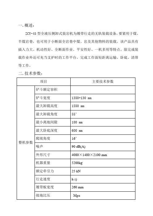
一.概述:ZCY-45型全液压侧卸式装岩机为履带行走的无轨装载设备,要紧用于煤、半煤岩巷,也可用于小断面全岩巷中煤、岩及其他物料的装载。
该产品具有插入力大、机动性好、全断面作业、平安性好、一机多用等特点。
除完成装载作业外还可充当支护时的工作平台,完成工作面短距离运输、卧底、清帮等工作。
二.技术参数:续表2. 型号含义Z C Y - 45铲斗容积(立方米)100倍电液驱动型式铲斗向侧面卸载装岩机三.要紧组成部份:该设备以电机为动力,液压马达驱动履带行走、液压油缸操作铲斗的全液压侧卸式装载设备。
它由:1工作机构、2液压系统、3机架、4履带行走部份、5冷却系统、6电气系统等部份组成。
见图1。
当转斗油缸活塞杆收缩、铲斗翻转后与铲斗臂、支架间形成平行机构,现在举升,铲斗可不能前倾或后仰。
操作侧卸油缸可使铲斗向一侧倾斜,达到卸载的目的。
铲斗通过销轴与铲斗座铰接,铲斗座与铲斗臂靠销轴连接。
铲斗臂上部与机架铰接。
铲斗前部铲板为耐磨钢板,可用于装载磨蚀性很高的物料,如硬砂岩等。
通过调换铲斗与侧卸油缸销轴的位置及铲斗挡板和料口的彼此位置,即可实现左右方向侧卸的调换。
2.液压系统:液压系统由三联泵、左右行走马达、液压油缸、操纵阀、主副油箱及其附件等组成开式系统。
工作原理见图3。
图3左右行走马达各自由三联泵的两联定量齿轮泵单独供油。
系统的最高压力为16MPa。
液压油缸由三联泵中余下的一联定量齿轮泵单独供油,最高压力16MPa。
行走马达回路中,高压油经泵、换向阀、别离抵达左、右行走马达,驱动设备前进或后退。
回油经换向阀、滤油器回到油箱,左右马达泄油口直接通主油箱。
工作机构液压回路中,高压油经换向阀别离抵达转斗油缸、举升油缸和侧卸油缸,回油经换向阀、滤油器回副油箱。
主副油箱之间由软管相连,系统的压力由换向阀上的进油口一侧的平安溢流阀调剂螺钉调定,出厂时已经调定,用户一样无需再调。
工作机构多路换向阀的中位能够临时封油,即操纵手柄在中位时,油缸可临时相对固定不动。
JOYO-J集控防误系统使用说明书共 114 页文件审批:文件修改记录:阅读指南文档目标:本手册主要是针对珠海优特电力科技股份有限公司所的JOYO-J综合防误系统提供的操作说明,以使该产品的使用者能够了解产品的功能、性能和特点,快速掌握产品的使用方法及维护方法。
阅读对象:本说明书是为JOYO-J综合防误系统的使用者所编写的,主要内容有日常的开票操作和常用的参数配置方法,主要作用是给操作人员的日常使用提供帮助和操作指引。
文档构成:本使用说明书主要由概述、系统配置及安装、开操作票、现场操作、系统查询、数据管理、基本配置、独立运行、数据备份与还原、图形控制等几部分组成。
文档约定:本手册针对本系统的常用功能作操作说明、对于钥匙相关的操作部分,请参考相关的钥匙使用操作手册,对于系统的不常用功能或者某个项目特殊增加的功能,请参阅相关的特殊使用说明文档,或者咨询我公司的调试人员。
前言本说明书的目标读者为JOYO-J集控防误系统的直接用户,是系统安装、调试完成以后的使用说明书,主要用来帮助用户了解JOYO-J集控防误系统的构成、特点,说明本系统的具体操作过程,并指导用户进行简单的系统维护。
本说明书内容分三个大部分,第一、第二章为系统介绍及安装,第三章~第六章为用户日常操作使用说明,第七章~第十二章为系统维护部分。
本说明书以指导用户操作使用为重点,以“用户登录→开操作票→传票→现场操作→任务结束→数据查询”为流程对整个操作过程作详细的指导说明。
为了指导用户对本系统进行简单的维护,本书将JOYO-J集控系统PC客户端常用菜单功能都作了详细说明,但由于本系统对使用者有严格的权限控制,只有相应权限的用户才能使用对应的菜单功能。
所以本说明书中所涉及的部分菜单和功能可能你无法看到或使用,请用户注意。
本说明书中所涉及得电脑钥匙的相关操作,请查阅相关型号电脑钥匙的使用说明书。
目录第1章概述 .................................................. 错误!未定义书签。
用户手册USER’S MANUALXJ9100系列电力网络仪表XJ9100 Series Network Power metersVER2.0许继测控仪表有限公司Xu Ji Measure& Control Meters Co., LtdCopyRight? 2008 XJ9100 Ver2.0Xu Ji Measure & Control Meters Co., Ltd版权所有,未经本公司书面许可,此手册中的任何段落和章节均不得被摘抄、复制与传播。
本公司保留对手册所描述之产品规格修改的权利,恕不另行通知,订货之前,欢迎垂询以确定最新订货信息。
本手册不适用于未受训者,维护、安装工作只由有资质的人完成。
目录一、产品简介....................................................................二、技术参数.................................................... 错误!未定义书签。
三、安装........................................................................3.1产品外形尺寸和安装方法.....................................................3.2接线.......................................................................3.2.1 后接线端子图..........................................................3.2.2 端子说明..............................................................3.3接线图 .....................................................................3.4辅助电源 ...................................................................3.5输入信号 ...................................................................四、操作与使用..................................................................4.1屏幕显示说明...............................................................4.1.1屏幕全部显示图..........................................................4.1.2显示字符说明............................................................4.1.3 按键定义..............................................................4.1.4 仪表具体页面...........................................................4.2参数设置 ...................................................................五、通信和输出..................................................................5.1通信协议 (11)5.2通讯应用格式说明 ...........................................................5.3读继电器输出状态(功能码01)...............................................5.4读数字输入状态(功能码02).................................................5.5读数据(功能码03).........................................................5.6控制继电器输出(功能码05)................................................5.7预置多寄存器(功能码16)...................................................5.8XJ9100系列通讯地址表......................................................六、产品选型....................................................................6.1产品命名方法...............................................................6.2快速选型指南...............................................................七、订货说明....................................................................7.1订货举例....................................................................7.2联系我们 (20)一、产品简介XJ9100系列多功能电力仪表采用最现代的微处理器和数字信号处理技术设计而成。
集合全面的三相电量测量/显示、故障报警、数字输入/输出与网络通讯于一身。
大屏幕、高清晰液晶显示。
可作为仪表单独使用,取代大量传统的模拟仪表,亦可作为电力监控系统(SCADA)之前端元件,用以实现远程数据采集与控制。
工业标准的RS-485通讯接口和Modbus通讯协议,是SCADA系统集成的理想选择。
XJ9100虽然是以测量为主的仪表,但它还附带了丰富、灵活的I/O功能,这使得它完全可以胜任作为分布式RTU的要求,实现遥信、遥测、遥控、计量于一体。
主要应用于变配电自动化、智能型开关盘柜、业自动化、智能建筑能源管理系统等。
二、技术参数电源电压范围AC/DC 126V~256V 功耗<5VA绝缘电阻≥100MΩ工频耐压电源、输入、输出之间 2kV/1min(AC正弦波有效值)平均无故障工作时间≥50000h工作条件温度:-10℃~45℃;湿度:≤93%;无腐蚀性气体海拔高度≤2500m三、安装3.1 产品外形尺寸和安装方法⏹在需要安装仪表的盘上,开一91mm ×91mm的方孔;⏹将仪表取出后去掉四角的安装夹子,带脉冲量或模拟量输出功能的仪表,把上边端子拔掉,然后从前插入到仪表孔中;⏹把四支安装卡子分别从后部顺着仪表四边的沟槽装上,并向前推紧卡子;再把去掉端子按原方向插紧即可。
3.2 接线3.2.1 后接线端子图3.2.2 端子说明下排:电流输入端子号 4 5 6 7 8 9信号IA* IA IB* IB IC* IC 左排:开关量输出端子21 22 23 24 25 26 27 28 备注号常开型继电信号DO1 DO2 DO3 DO4器右排:开关量输入端子号30 31 32 33 34 35 36 37信号COM DI6 DI5 DI4 DI3 DI2 DI1 NC 上排:电压输入/工作电源/通信输出功能RS-485通信电压信号输入辅助电源端子58 59 60 11 12 13 14 1 2 3号信号 A B 地UA UB UC UN L N G 顶排:电能脉冲输出/模拟量输出功能有功电能脉冲输出无功电能脉冲输出模拟量输出端子号46 47 48 49 15 16 信号P0+ P0- P1+ P1- IO- IO+ 3.3 接线图3.4 辅助电源XJ9100系列仪表的供电电源为126~256Vac(50/60Hz),辅助电源回路中必须加装保险丝或小型空气断路器,保险丝可选用1A/250Vac。
电源供电可以由独立电源回路供给,也可以从被测线路取得。
建议在电源电压波动较大的条件下,应使用电压稳定装置。
典型的辅助电源接线如下:126~256V AC为了提高抗干扰能力,建议在辅助电源回路中加装浪涌抑制器或脉冲群抑制器。
接线如下:126~256V AC3.5 输入信号⏹电压输入:输入电压不应高于额定输入电压的120%,否则,应考虑加装PT。
电压输入信号回路中必须安装1A保险丝或小型空气断路器。
⏹电流输入:额定电流值一般为5安培,CT的选择建议CT精度优于0.5%,容量不小于3VA。
CT接线电缆应尽量短,过长的线路会带来额外的误差。
在工程应用中,可能会出现实际负荷远远小于系统负荷容量的情况,这会影响电流测量的精度,如果出现这种情况,建议提高CT精度等级,或在允许情况下依据实际负荷重新选择CT。
注意:在任何情况下,CT 回路都不允许开路,CT 回路中不允许加装保险丝和任何形式的开关。
实际应用中CT 的一端应连接大地。
输入电流、电压相序一致,编程设置的输入网络与测量负载接线方式应一致。
开关量输入:开关量输入示意图当开关K打开时,光电耦合器的二极管侧无电流通过,三极管处于截止状,OUT端为低电平;当开关K 闭合时,光电耦合器的二极管侧有电流通过,三极管处于导通状态,OUT端为高电平。
这样OUT的高、低电平分别对应K的“合”与“分”状态。
推荐与开关K 串联的电源电压范围为12~24Vdc,如果连接的线路比较长,为了防止干扰也可以适当提高电源电压,回路电流应在1 0 mA~15mA,最大电流不能超过30mA。
为了方便用户在现场的使用,仪表提供了一组15Vdc,容量1W的辅助电源。
这样用户可以避免外配电源的麻烦。
此电源使用时的容量也须在允许范围之内,否则可能会引起损坏。
3.6 输出信号模拟量输出XJ9100提供一路模拟量输出,输出信号为:DC 4~20mA或DC 0~5V,具体变送的电量可通过设置选择,如果三相四线方式,可选参数有:相电压UA、UB、UC、电流IA、IB、IC、线电压UAB、UBC、UCA、有功功率PA、PB、PC、P、无功功率QA、QB、QC、Q、视在功率SA、SB、SC、S、功率因数PFA、PFB、PFC、PF、频率F;如为三相三线方式,则可选参数为:线电压UAB、UBC、UCA、电流IA、IB、IC、总有功功率P、总无功功率Q、总视在功率S、总功率因数PF、频率F。