SMAJ11CA-13-F中文资料
- 格式:pdf
- 大小:80.59 KB
- 文档页数:4
道岔启动电路及表示电路说明1、道岔表示电路的技术条件1.只能用继电器的吸起状态与道岔的正确位置相对应,分别设置道岔定位表示继电器DBJ和道岔反位继电器FBJ。
2.当室外联系线路发生混线或混入其他电源时,必须保证不致使DBJ或FBJ错误吸起。
3.当道岔在转换或发生挤岔事故、停电或断线等故障时,必须保证DBJ或FBJ失磁落下,因此必须使用安全型继电器。
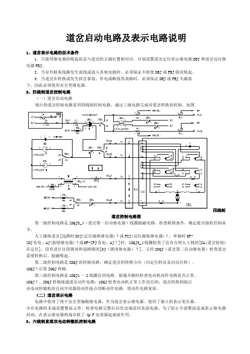
2、四线制道岔控制电路(一)道岔启动电路现行的道岔控制电路采用四线制控制电路,通过三级电路完成对道岔转换的控制,如图四线制道岔控制电路图第一级控制电路是lDQJ3_4(道岔第一启动继电器)线圈励磁电路,检查联锁条件,确定能否接收控制命令。
人工操纵道岔[选路时DCJ(定位操纵继电器)↑或FCJ(反位操纵继电器)↑,单操时KF-ZDJ有电、AJ(按钮继电器)↑或KF-ZFJ有电、AJ↑]时,lDQJ3_4线圈检查了没有办理人工锁闭[CA(道岔按钮)在定位],没有进行区段锁闭和进路锁闭[SJ(锁闭继电器)↑],又经2DQJ(道岔第二启动继电器)检查道岔需要转换后,励磁吸起。
第二级控制电路是2DQJ的转极电路,确定道岔的转换方向(向定位转还是向反位转)。
1DQJ↑后使2DQJ转极。
第三级控制电路是1DQJ1一2线圈自闭电路。
接通并随时检查电动机动作电路是否正常。
1DQJ↑、2DQJ转极接通道岔动作电路:1DQJ检查电动机正常工作而自闭,道岔转换到底后由电动转辙机的自动开闭器的动作接点切断动作电路,使动作电路复原。
(二)道岔表示电路电路中使用了两个安全型偏极继电器,作为道岔表示继电器,使用了独立的表示变压器,并在电路的末端设置整流元件,检查电路完整后向发送端送回直流电源,为了防止半波整流造成表示继电器抖动,在表示继电器两端并联了4μF电容器起滤波作用。
3、六线制直流双电动转辙机控制电路当轨道线路采用12号60 kg/m AT道岔时,一台转辙机已经适应不了转换力和牵引力的要求。

SOCAY双向TVS二极管SMAJ13CA型号说明
硕凯电子(Sylvia)
一、产品图
1、为表面安装应用优化电路板空间
2、低泄漏
3、单向单元
4、玻璃钝化结
5、低电感
6、优良的钳位能力
7、400W的峰值功率能力在10×1000μ波形重复率(占空比):0.01%
8、快速响应时间:从0伏特到最小击穿电压通常小于1.0ps
9、典型的,在电压高于12V时,反向漏电流小于5μA
10、高温焊接:终端260°C/40秒
11、典型的最大温度系数△Vbr=0.1%x Vbr@25°C x△T
12、塑料包装有保险商实验室可燃性94V-0
13、无铅镀雾锡
14、无卤化,符合RoHS
15、典型失效模式是在指定的电压或电流下出现
16、晶须测试是基于JEDEC JESD201A每个表4a及4c进行的
17、IEC-61000-4-2ESD15kV(空气),8kV(接触)
18、数据线的ESD保护符合IEC61000-4-2(IEC801-2)
19、数据线的EFT保护符合IEC61000-4-4(IEC801-4)
三、应用范围
TVS器件非常适合保护I/O接口,Vcc总线和其他应用于电信、计算机、工业和消费电子应用的易损电路。
五、UL认证编号
六、特性曲线
七、产品尺寸。
AF140-30-11-13Extended Product Type:Product ID:EAN:Minimum Order Quantity:Customs Tariff Number:EAN:Product Net Depth:Product Net Height:Package Level 1 Width:Package Level 1 Length:Package Level 1 Height:Package Level 1 Gross Weight:Number of Main Contacts NC:Number of Auxiliary Contacts NO:Number of Auxiliary Contacts NC:Rated Operational Voltage:Rated Frequency (f):Conventional Free-air Thermal Current (I th ):Rated Operational Current AC-1 (I e ):Rated Operational Current AC-3 (I e ):Rated Operational Power AC-3 (P e ):Rated Breaking Capacity AC-3 acc.to IEC 60947-4-1:Rated Making Capacity AC-3 acc. to IEC 60947-4-1:Short-Circuit Protective Devices:Rated Short-time Withstand Current (I cw ):Maximum Breaking Capacity:General Inform ationAF140-30-11-13 100-250V 50/60Hz / DC 1SFL447001R13117320500476949Ordering1 piece 853649007320500476949Dim ensions126.0 mm 150.0 mm Container Inform ation194 mm 115 mm 169 mm 1.57 kg Technical011Main Circuit 690 V Main Circuit 50/60 Hz acc. to IEC 60947-4-1, Open Contactors q = 40 °C 200 A (690 V) 55 °C 175 A (690 V) 40 °C 200 A (690 V) 70 °C 160 A (690 V) 55 °C 80 A (415 V) 55 °C 140 A (220 / 230 / 240 V) 55 °C 140 A (440 V) 55 °C 140 A (380 / 400 V) 55 °C 140 A (500 V) 55 °C 130 A(500 V) 90 kW (690 V) 75 kW (220 / 230 / 240 V) 37 kW (380 / 400 V) 75 kW (440 V) 90 kW (415 V) 75 kW8 x Ie AC-310 x Ie AC-3gG Type Fuses 315 Aat 40 °C Ambient Temp, in Free Air, from a Cold State 15 min 200 A at 40 °C Ambient Temp, in Free Air, from a Cold State 30 s 674 A at 40 °C Ambient Temp, in Free Air, from a Cold State 10 s 1168 A at 40 °C Ambient Temp, in Free Air, from a Cold State 1 s 1460 A at 40 °C Ambient Temp, in Free Air, from a Cold State 1 min 477 Acos phi=0.45 (cos phi=0.35 for Ie > 100 A) at 440 V 3000 A cos phi=0.45 (cos phi=0.35 for Ie > 100 A) at 690 V 1500 A AF140-30-11-13 100-250V 50/60Hz / DCMaximum Electrical Switching Frequency:Rated Operational Current DC-1 (I e):Rated Operational Current DC-3 (I e):Rated Operational Current DC-5 (I e):Rated Insulation Voltage (U i):Rated Impulse Withstand Voltage (U imp):Mechanical Durability:Maximum Mechanical Switching Frequency:Coil Operating Limits:Rated Control Circuit Voltage (U c): Coil Consumption:Operate Time:Connecting Capacity Main Circuit:Connecting Capacity Auxiliary Circuit:Degree of Protection:Terminal Type:Number of Main Contacts NO:Maximum Operating Altitude Permissible:RoHS Status:Ambient Air Temperature:General Use Rating UL/CSA: Horsepower Rating UL/CSA:Maximum Operating VoltageUL/CSA:Instructions and Manuals:CB Certificate:CCC Certificate:Data Sheet, Technical Information: Declaration of Conformity - CE: RINA Certificate:RoHS Information:ETIM 4:ETIM 5:UNSPSC:AC-3 300 cycles per hourAC-1 300 cycles per hourAC-2 / AC-4 150 cycles per hour(110 V) 2 Poles in Series, 40 °C 160 A(220 V) 3 Poles in Series, 40 °C 160 A(110 V) 2 Poles in Series, 40 °C 160 A(220 V) 3 Poles in Series, 40 °C 160 A(110 V) 2 Poles in Series, 40 °C 160 A(220 V) 3 Poles in Series, 40 °C 160 Aacc. to UL/CSA 600 Vacc. to IEC 60947-4-1 and VDE 0110 (Gr. C) 690 VMain Circuit 8 kV5 million300 cycles per hour(acc. to IEC 60947-4-1) 0.85 x Uc Min. ... 1.1 x Uc Max. (at θ ≤ 70 °C) °C 60 Hz 100…250 V50 Hz 100…250 VDC Operation 100…250 VPull-in at Max. Rated Control Circuit Voltage 60 Hz 130 V·AHolding at Max. Rated Control Circuit Voltage DC 3 WHolding at Max. Rated Control Circuit Voltage 50 Hz 6 V·APull-in at Max. Rated Control Circuit Voltage DC 135 WPull-in at Max. Rated Control Circuit Voltage 50 Hz 130 V·AHolding at Max. Rated Control Circuit Voltage 60 Hz 6 V·ABetween Coil Energization and NO Contact Closing 25…55 ms Between Coil De-energization and NO Contact Opening 37…47 ms Rigid Cu-Cable 2x10…95 mm²Flexible 2x10…70 mm²Solid 2x1…4 mm²Flexible with Insulated Ferrule 2x0.75…2.5 mm²Stranded 2x1…4 mm²Flexible 2x0.75…2.5 mm²Flexible with Ferrule 2x0.75…2.5 mm²acc. to IEC 60529, IEC 60947-1, EN 60529 Coil Terminals IP20acc. to IEC 60529, IEC 60947-1, EN 60529 Main Terminals IP00 Double Clamp3Environm ental3000 mFollowing EU Directiv e 2002/95/EC August 18, 2005 and amendmentClose to Contactor Fitted with Thermal O/L Relay (0.85 ... 1.1 Uc) -25…+50 °CClose to Contactor without Thermal O/L Relay (0.85 ... 1.1 Uc) -40…+70 °CClose to Contactor for Storage -40…+70 °CTechnical UL/CSA(600 V AC) 200 A(208 V AC) Three Phase 40 Hp(440 ... 480 V AC) Three Phase 100 Hp(550 ... 600 V AC) Three Phase 125 Hp(220 ... 240 V AC) Three Phase 50 Hp(200 V AC) Three Phase 40 HpMain Circuit 600 VCertificates and Declarations (Docum ent Num ber)1SFC100003M0201SE-70480CQC_20130103046040551SFC101070D02012CMT004242ELE060313X G/0021SFC101055D0202ClassificationsEC000066 - Magnet contactor, AC-switchingEC000066 - Magnet contactor, AC-switching39121529AF140-30-11-13。
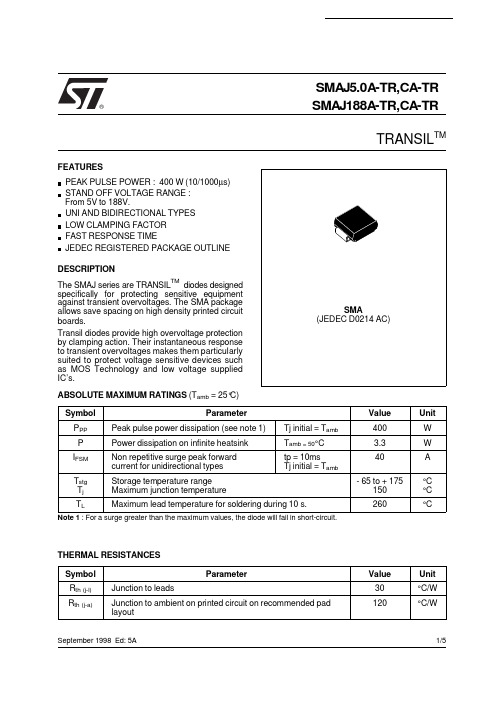
SMAJ5.0A-TR,CA-TR SMAJ188A-TR,CA-TRTRANSIL TM®PEAK PULSE POWER : 400 W (10/1000µs)STAND OFF VOLTAGE RANGE :From 5V to 188V.UNI AND BIDIRECTIONAL TYPES LOW CLAMPING FACTOR FAST RESPONSE TIMEJEDEC REGISTERED PACKAGE OUTLINE FEATURESSMA(JEDEC D0214 AC)Symbol ParameterValue Unit P PP Peak pulse power dissipation (see note 1)Tj initial = T amb 400W P Power dissipation on infinite heatsink T amb = 50°C 3.3W I FSM Non repetitive surge peak forward current for unidirectional types tp = 10msTj initial = T amb40A T stg T j Storage temperature range Maximum junction temperature- 65 to + 175150°C °C T LMaximum lead temperature for soldering during 10 s.260°CNote 1 : For a surge greater than the maximum values, the diode will fail in short-circuit.ABSOLUTE MAXIMUM RATINGS (T amb = 25°C)DESCRIPTIONThe SMAJ series are TRANSIL TM diodes designed specifically for protecting sensitive equipment against transient overvoltages. The SMA package allows save spacing on high density printed circuit boards.Transil diodes provide high overvoltage protection by clamping action. Their instantaneous response to transient overvoltages makes them particularly suited to protect voltage sensitive devices such as MOS Technology and low voltage supplied IC’s.September 1998 Ed: 5A Symbol ParameterValue Unit R th (j-l)Junction to leads30°C/W R th (j-a)Junction to ambient on printed circuit on recommended pad layout120°C/WTHERMAL RESISTANCES 1/5捷多邦,您值得信赖的PCB打样专家!II F V F V CLV BRV RMI PPI RMVSymbol ParameterV RM Stand-off voltage V BR Breakdown voltage V CL Clamping voltage I RM Leakage current @ V RM I PPPeak pulse currentαTVoltage temperature coefficient V FForward voltage dropELECTRICAL CHARACTERISTICS (T amb = 25°C)TypesI RM @ V RM V BR @ I R V CL @ I PP V CL @ I PP αT C maxmin maxmaxmaxtyp note210/1000µs 8/20µs note3note4Unidirectional Mark.Bidirectional Mark. µA V V mA V A V A 10-4/°C pF SMAJ5.0A-TR AE SMAJ5.0CA-TR AA 800 5.0 6.4109.243.513.4174 5.73500SMAJ6.0A-TR DUB SMAJ6.0CA-TR DBB 800 6.0 6.71010.338.813.7170 5.93300SMAJ6.5A-TR DUC SMAJ6.5CA-TR DBC 500 6.57.21011.235.714.5160 6.13100SMAJ8.5A-TR DUH SMAJ8.5CA-TR DBH 108.59.44114.427.718.61247.32000SMAJ10A-TR AX SMAJ10CA-TR AC 51011.111723.521.71067.81550SMAJ12A-TR DUK SMAJ12CA-TR DBK 51213.3119.920.125.3918.31325SMAJ13A-TR BG SMAJ13CA-TR BH 11314.4121.518.627.2858.41200SMAJ15A-TR BM SMAJ15CA-TR AJ 11516.7124.416.432.5718.8975SMAJ18A-TR DUQ SMAJ18CA-TR DBQ 11820129.213.739.3599.2800SMAJ20A-TR DUR SMAJ20CA-TR DBR 12022.2132.412.342.8549.4725SMAJ22A-TR DUS SMAJ22CA-TR DBS 12224.4135.511.248.3489.6625SMAJ24A-TR DUT SMAJ24CA-TR DBT 12426.7138.910.350469.6600SMAJ26A-TR DUU SMAJ26CA-TR DBU 12628.9142.19.553.5439.7575SMAJ28A-TR CG SMAJ28CA-TR CH 12831.1145.48.859399.8510SMAJ30A-TR CK SMAJ30CA-TR CL 13033.3148.48.364.3369.9480SMAJ33A-TR CM SMAJ33CA-TR CN 13336.7153.37.569.73310.0450SMAJ40A-TR DUZ SMAJ40CA-TR DBZ 14044.4164.5 6.2842710.1370SMAJ43A-TR EUA SMAJ43CA-TR EBA 14347.8169.4 5.7912510.2350SMAJ48A-TR CX SMAJ48CA-TR CY 14853.3177.4 5.21002310.3320SMAJ58A-TR EUF SMAJ58CA-TR EBF 15864.4193.6 4.31211910.4270SMAJ70A-TR EUI SMAJ70CA-TR EBI 17077.81113 3.51461610.5230SMAJ85A-TR EUL SMAJ85CA-TR EBL 18594.41137 2.91781310.6200SMAJ100A-TR EUN SMAJ100CA-TR EBN 11001111162 2.52121110.7170SMAJ130A-TR EUQ SMAJ130CA-TR EBQ 11301441209 1.9265910.8145SMAJ154A-TR EUT SMAJ154CA-TR EBT 11541711246 1.6317710.8125SMAJ170A-TR SR SMAJ170CA-TR SS 11701891275 1.4353 6.510.8120SMAJ188A-TREUV SMAJ188CA-TR EBV 11882091328 1.4388610.8110Note 2 :Pulse test : t p < 50 ms.Note 3 :∆V BR = αT * (T amb - 25) * V BR (25°C).Note 4 :V R = 0 V, F = 1 MHz. For bidirectional types,capacitance value is divided by 2.10s1000s%I PP 50tPULSE WAVEFORM 10/1000s100SMAJxxxA-TR, CA-TR2/52550751001251501750.00.10.20.30.40.50.60.70.80.91.01.1Ppp[Tj initial]/Ppp[Tj initial=25°C]Tj initial(°C)Fig 1: Peak power dissipation versus initial junction temperature.0.010.101.0010.0010010005000Ppp(W)tp(ms)Fig 2: Peak pulse power versus exponential pulse duration (Tj initial=25°C).1101005000.11.010.0100.0200.0Ipp(A)tp=20µstp=1ms SMAJ5.0A,CASMAJ188A,CASMAJ58A,CASMAJ26A,CASMAJ13A,CAV (V)CL Fig 3: Clamping voltage versus peak pulse current (Tj initial=25°C)Exponential waveform tp=20µs & tp=1ms.1101002001010010005000C(pF)F=1MHzSMAJ5.0ASMAJ188ASMAJ58ASMAJ26A SMAJ13A V (V)R Fig 4-1: Capacitance versus reverse applied voltage (typical values) (SMAJxxA).11010020011010010002000F=1MHzSMAJ5.0CA SMAJ188CASMAJ58CA SMAJ26CA SMAJ13CAC(pF)V (V)R Fig 4-2: Capacitance versus reverse applied voltage (typical values) (SMAJxxCA).SMAJxxxA-TR, CA-TR3/50.40.50.60.70.80.9 1.0 1.1 1.2 1.3 1.40.010.101.0010.00I (A)FM Tj=25°CTj=125°CV (V)FM Fig 5: Peak forward voltage drop versus peak forward current (typical values).1E-21E-11E+01E+11E+25E+20.010.101.00Zth(j-a)/Rth(j-a)tp(s)Fig 6: Relative variation of thermal impedance junction to ambient versus pulse duration.12345405060708090100110120130140Rth(j-a) (°C/W)S(Cu)(cm²)Fig 7: Thermal resistance junction to ambient versus copper surface under each lead (printed circuit board FR4 e(Cu)=35µm).2550751001251501E-11E+01E+11E+21E+32E+3I [Tj] / I [Tj=25°C]R R V < 8.5VBR Tj(°C)V 8.5VBR ≥Fig 8: Relative variation of leakage current versus junction temperature.SMAJxxxA-TR, CA-TR4/5REF.DIMENSIONSMillimeters Inches Min.Max.Min.Max.A11.902.700.0750.106A20.050.200.0020.008b1.25 1.650.0490.065c 0.150.410.0060.016E4.805.600.1890.220E13.954.600.1560.181D 2.25 2.950.0890.116L0.751.600.0300.063Information furnished is believed to be accurate and reliable. However, STMicroelectronics assumes no responsibility for the consequences of use of such information nor for any infringement of patents or other rights of third parties which may result from its use. No license is granted by implication or otherwise under any patent or patent rights of STMicroelectronics.Specifications mentioned in this publication are subject to change without notice. This publication supersedes and replaces all information previously supplied.STMicroelectronics products are not authorized for use as critical components in life support devices or systems without express written approval of STMicroelectronics.The ST logo is a registered trademark of STMicroelectronics © 1998 STMicroelectronics - Printed in Italy - All rights reserved.STMicroelectronics GROUP OF COMPANIESAustralia - Brazil - Canada - China - France - Germany - Italy - Japan - Korea - Malaysia - Malta - Mexico - Morocco -The Netherlands - Singapore - Spain - Sweden - Switzerland - Taiwan - Thailand - United Kingdom - U.S.A.Packaging : standard packaging is in tape and reel.PACKAGE MECHANICAL DATA SMA (Plastic)ECLE1DA1A2bMARKING : Logo, Date Code, Type Code, Cathode Band (for unidirectional types only).FOOTPRINT DIMENSIONS (Millimeter)SMA Plastic.2.40 1.651.45 1.45Weight = 0.068 gORDER CODESM A J 85 C A - TRBIDIRECTIONALNo suffix : UnidirectionalSURFACE MOUNTSTAND OFF VOLTAGE400 WATTSTAPE & REEL SMAJxxxA-TR, CA-TR5/5。
Document Number 17249Surface Mount ESD Protection DiodesFeatures•For surface mounted applications •Low-profile package•Optimized for LAN protection applications •Ideal for ESD protection of data lines in accordance with IEC 61000-4-2 (IEC801-2) •Ideal for EFT protection of data lines in accordance with IEC 61000-4-4 (IEC801-4) •IEC 61000-4-2 (ESD) 15 kV (air) 8 kV (contact) •Low incremental surge resistance, excellent clamping capability •200 W peak pulse power capability with a 10/1000 µs waveform, repetition rate (duty cycle): 0.01 % •Very fast response time•High temperature soldering guaranteed:260°C/ 10 seconds at terminals •Lead (Pb)-free component•Component in accordance to RoHS 2002/95/EC and WEEE 2002/96/ECMechanical DataCase: JEDEC DO-219AB (SMF ®) Plastic case Terminals: Solder plated, solderable per MIL-STD-750, Method 2026Polarity:The band denotes the cathode, which is positive with respect to the anode under normal TVS operationMounting Position: Any Weight: approx. 15 mgPackaging Codes/Options:GS18 / 10 k per 13 " reel (8 mm tape), 50 k/box GS08 / 3 k per 7 " reel (8 mm tape), 30 k/boxAbsolute Maximum RatingsRatings at 25°C, ambient temperature unless otherwise specified1)Non-repetitive current pulse and derated above T A = 25°CThermal CharacteristicsRatings at 25°C, ambient temperature unless otherwise specified2) Mounted on epoxy glass PCB with 3 x 3 mm, Cu pads ( ≥ 40 µm thick)ParameterT est conditionSymbol Value Unit Peak pulse power dissipation 10/1000 µs waveform 1)P PPM 200W 8/20 µs waveform 1)P PPM 1000W Peak pulse current 10/1000 µs waveform 1)I PPM next Table A Peak forward surge current8.3 ms single half sine-waveI FSM20AParameterT est conditionSymbol Value Unit Thermal resistance 2)R thJA 180K/W Operation junction and storage temperature rangeT stg , T J- 55 to + 150°C Document Number 85811Electrical CharacteristicsRatings at 25°C ambient temperature unless otherwise specified. V F = 3.5 V at I F = 12 A (uni-directional only)1) Pulse test t p≤ 5.0 ms2)Surge current waveform 10/1000 µs3) All terms and symbols are consistent with ANSI/IEEE C62.35PartnumberMarking Code UNIBreakdown Voltage 1)Test CurrentStand-off VoltageMaximum Reverse Leakage Maximum Peak Pulse Surge Current 2,3)Maximum Clamping VoltageJunction CapacitanceV (BR)@ I TV WM@ V WMI D I PPM@ I PPM V CC j @ V R = 0 V, f = 1 MHzV mA V µA AV pF mintypSMF5V0A AE 6.4010 5.040021.79.21030SMF6V0A AG 6.6710 6.040019.410.31010SMF6V5A AK 7.2210 6.525017.911.2850SMF7V0A AM 7.78107.010016.712.0750SMF7V5A AP 8.33 1.07.55015.512.9730SMF8V0A AR 8.89 1.08.02514.713.6670SMF8V5A AT 9.44 1.08.51013.914.4660SMF9V0A AV 10.0 1.09.0 5.013.515.4620SMF10A AX 11.1 1.010 2.511.817.0570SMF11A AZ 12.2 1.011 2.511.018.2460SMF12A BE 13.3 1.012 2.510.119.9440SMF13A BG 14.4 1.013 1.09.321.5420SMF14A BK 15.6 1.014 1.08.623.2370SMF15A BM 16.7 1.015 1.08.224.4350SMF16A BP 17.8 1.016 1.07.726.0340SMF17A BR 18.9 1.017 1.07.227.6310SMF18A BT 20.0 1.018 1.0 5.829.2305SMF20A BV 22.2 1.020 1.0 6.232.4207SMF22A BX 24.4 1.022 1.0 5.635.5265SMF24A BZ 26.7 1.024 1.0 5.138.9240SMF26A CE 28.9 1.026 1.0 4.842.1225SMF28A CG 31.1 1.028 1.0 4.445.4210SMF30A CK 33.3 1.030 1.0 4.148.4205SMF33A CM 36.7 1.033 1.0 3.853.3190SMF36A CP 40.0 1.036 1.0 3.458.1180SMF40A CR 44.4 1.040 1.0 3.164.5165SMF43A CT 47.8 1.043 1.0 2.969.4160SMF45A CV 50.0 1.045 1.0 2.872.7155SMF48A CX 53.3 1.048 1.0 2.677.4150SMF51ACZ56.71.0511.02.482.4145Document Number Typical Characteristics (Tamb = 25 °C unless otherwise specified)Figure 1. Peak Pulse Power RatingFigure 2. Pulse Derating CurveFigure 3. Pulse WaveformP P P M -P e a k P u l s e P o w e r (k W )0.11100.1µ s 1.0µ s 10µ s t d -Pulse Width (sec.)100µ s 1.0ms 10ms172502550751000752550100125150175200P e a k P u l s e P o w e r (P P P )o r C u r r e n t (I P P M )D e r a t i n g i n P e r c e n t a g e ,%T A -Ambient Temperature (°C)17251I P P M -P e a k P u l s e C u r r e n t ,%I R S M2.0t -Time (ms)17252Package Dimensions in mm (Inches) Document Number 85811Blistertape for SMFDocument Number Ozone Depleting Substances Policy StatementIt is the policy of Vishay Semiconductor GmbH to1.Meet all present and future national and international statutory requirements.2.Regularly and continuously improve the performance of our products, processes, distribution and operatingsystems with respect to their impact on the health and safety of our employees and the public, as well as their impact on the environment.It is particular concern to control or eliminate releases of those substances into the atmosphere which are known as ozone depleting substances (ODSs).The Montreal Protocol (1987) and its London Amendments (1990) intend to severely restrict the use of ODSs and forbid their use within the next ten years. Various national and international initiatives are pressing for an earlier ban on these substances.Vishay Semiconductor GmbH has been able to use its policy of continuous improvements to eliminate the use of ODSs listed in the following documents.1.Annex A, B and list of transitional substances of the Montreal Protocol and the London Amendmentsrespectively2.Class I and II ozone depleting substances in the Clean Air Act Amendments of 1990 by the EnvironmentalProtection Agency (EPA) in the USA3.Council Decision 88/540/EEC and 91/690/EEC Annex A, B and C (transitional substances) respectively. Vishay Semiconductor GmbH can certify that our semiconductors are not manufactured with ozone depleting substances and do not contain such substances.We reserve the right to make changes to improve technical designand may do so without further notice.Parameters can vary in different applications. All operating parameters must be validated for each customer application by the customer. Should the buyer use Vishay Semiconductors products for any unintended or unauthorized application, the buyer shall indemnify Vishay Semiconductors against all claims, costs, damages, and expenses, arising out of, directly or indirectly, any claim of personal damage, injury or death associated with such unintended or unauthorized use.Vishay Semiconductor GmbH, P.O.B. 3535, D-74025 Heilbronn, Germany Document Number 85811。


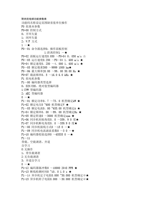
默纳克电梯功能参数表功能码名称设定范围缺省值单位操作F0 组基本参数F0-00 控制方式0:开环矢量1:闭环矢量2:V/F 方式1 -★F0—01 命令源选择0:操作面板控制1:距离控制1 -★F0-02 面板运行速度0.050 ~F0-04 0。
050 m/s ☆F0—03 运行速度0.250 ~F0—04 1。
600 m/s ★F0-04 额定速度0。
250 ~4。
000 1。
600 m/s ★F0—05 额定载重300 ~9999 1000 kg★F0—06 最大频率20.00 ~99。
00 50.00 Hz ★F0-07 载波频率0。
5 ~16.0 6.0 kHz ★F1 组电机参数F1—00 编码器类型选择0:SIN/COS、绝对值型编码器1:UVW 型编码器2:ABZ 型编码器0 -★F1—01 额定功率0。
7 ~75。
0 机型确定kW ★F1-02 额定电压0 ~600 机型确定V ★F1—03 额定电流0。
00 ~655.00 机型确定A ★F1-04 额定频率0。
00 ~99。
00 机型确定Hz ★F1-05 额定转速0 ~3000 机型确定rpm ★F1-06 同步机初始角度0.0 ~359。
9 0 度★F1-07 同步机断电角度0.0 ~359.9 0 度★F1—08 同步机接线方式0 ~15 0 -★F1—09 同步机电流滤波系数0 ~3 0 -★F1-10 编码器校验选择0 ~65535 0 -★F1—11带载、空载调谐、井道自学习0:无操作1:带负载调谐2:无负载调谐3:井道自学习0 -★F1-12 编码器脉冲数0 ~10000 2048 PPR ★F1-13 断线检测时间0 ~10。
0 1.0 s ★F1—14 异步机定子电阻0.000 ~30.000 机型确定Ω★F1-15 异步机转子电阻0.000 ~30.000 机型确定Ω★F1—16 异步机漏感抗0.00 ~300。

SMAJ5.0(C)A - SMAJ170(C)A 400W SURFACE MOUNT TRANSIENT VOLTAGESUPPRESSORFeaturesMaximum Ratings@ T A= 25°C unless otherwise specified·400W Peak Pulse Power Dissipation· 5.0V - 170V Standoff Voltages·Glass Passivated Die Construction·Uni- and Bi-Directional Versions Available·Excellent Clamping Capability·Fast Response Time·Plastic Material: UL FlammabilityClassification Rating 94V-0Mechanical Data·Case:SMA, Transfer Molded Epoxy·Terminals: Solderable per MIL-STD-202,Method 208·Also Available in Lead Free Plating (Matte TinFinish). Please see Ordering Information,Note 5, on Page 4·Polarity Indicator: Cathode Band(Note: Bi-directional devices have no polarityindicator.)·Marking: Date Code and Marking CodeSee Page 3·Weight:0.064 grams (approx.)·Ordering Info: See Page 3Notes: 1. Valid provided that terminals are kept at ambient temperature.2. Measured with 8.3ms single half sine-wave. Duty cycle = 4 pulses per minute maximum.3. Unidirectional units only.Notes: 4. Suffix C denotes Bi-directional device.5.V BR measured with I T current pulse = 300m s6. For Bi-Directional devices having V RWM of 10V and under, the I R is doubled.101001000100001101001000C ,J U N C T I O N C A P A C I T A N C E (p F )T V ,STANDOFF VOLTAGE (V)WM Fig.2Typical Total Capacitance255075100125150175200100755025T ,AMBIENT TEMPERATURE (°C)A Fig.1Pulse Derating CurveP E A K P U L S E D E R A T I N G I N %O F P E A K P O W E R O R C U R R E N T0123I ,P E A K P U L S E C U R R E N T (%I )P p pt,TIME (ms)Fig.4Pulse Waveform0.11.00.1101001.010100010000P ,P E A K P U L S E P O W E R (k W )d 1000.00.20.40.6255075100125150175200P M S T E A D Y S T A T E P O W E R D I S S I P A T I O N (W )(A V ),T , LEAD TEMPERATURE (°C)L Fig.6Steady State Power Derating Curve0.81.06050403020102510P E A K F O R W A R D S U R G E C U R R E N T ,(A )NUMBER OF CYCLES AT 60HzFig. 5 Maximum Non-Repetitive Surge Current20501001XX =Product type marking code (See Page 2)=Manufacturers’code marking YWW =Date code markingY =Last digit of year ex:2for 2002WW =Week code 01to52Marking InformationOrdering InformationNotes: 4.For Packaging Details, go to our website at /datasheets/ap02007.pdf.5. For Lead Free version (with Lead Free terminal finish) part number, please add "-F" suffix to part number above. Example: SMAJ170A-13-F.(Note 4)。

SMAJ5.0A THRU SMAJ188ASurface Mount T RANS Z ORB ® Transient Voltage Suppressors5V-188V 400W深圳市赛特微电子有限公司MECHANICAL DATACase: DO-214AC (SMA)Molding compound meets UL 94 V-0 flammability rating Base P/N-E3 - RoHS compliant, commercial grade Base P/NHE3 - RoHS compliant, AEC-Q101 qualifiedTerminals: Matte tin plated leads, solderable per J-STD-002 and JESD 22-B102M3 suffix meets JESD 201 class 1A whisker testPolarity: For uni-directional types the band denotes cathode end, no marking on bi-directional typesNotes(1) Non-repetitive current pulse, per fig. 3 and derated above T A= 25 °C per fig. 2. Rating is 300 W above 78 V (2) Mounted on 0.2" x 0.2" (5.0 mm x 5.0 mm) copper pads to each terminalFEATURES• Low profile package• Ideal for automated placement • Glass passivated chip junction• Available in uni-directional and bi-directional • 400 W peak pulse power capability with a 10/1000 μs waveform, repetitive rate (duty cycle): 0.01 % (300 W above 78 V) • Excellent clamping capability • Very fast response time• Low incremental surge resistance• Meets MSL level 1, per J-STD-020, LF maximum peak of 260 °C • AEC-Q101 qualifiedNotes(1) Pulse test: t p 50 ms(2) Surge current waveform per fig. 3 and derate per fig. 2(3) For bi-directional types having V WM of 10 V and less, the I D limit is doubled(4) All terms and symbols are consistent with ANSI/IEEE C62.35(5) For the bi-directional SMAJ5.0CA, the maximum V BR is 7.25 V(6) V F = 3.5 V at I F = 25 A (uni-directional only)C J - J u n c t i o n C a p a c i t a n c e (p F )I P P M - P e a k P u l s e C u r r e n t , % I R S MRATINGS AND CHARACTERISTICS CURVES(T A = 25 °C unless otherwise noted)100100.10.1110100100010 000t d - Pulse Width (μs)1.02.03.04.0t - Time (ms)Fig. 1 - Peak Pulse Power Rating CurveFig. 3 - Pulse Waveform10075 502510 000100010000255075100125 150 175 20010110100200T J - Initial Temperature (°C)V WM - Reverse Stand-Off Voltage (V)Fig. 2 - Pulse Power or Current vs. Initial Junction Temperature Fig. 4 - Typical Junction Capacitance2001005010110Number of Cycles at 60 Hz100Fig. 5 - Typical Transient Thermal ImpedanceFig. 6 - Maximum Non-Repetitive Forward Surge CurrentUni-Directional OnlyP e a k P u l s e P o w e r (P P P ) o r C u r r e n t (I P P ) D e r a t i n g i n P e r c e n t a g e , %P P P M - P e a k P u l s e P o w e r (k W )P e a k F o r w a r d S u r g e C u r r e n t (A )。
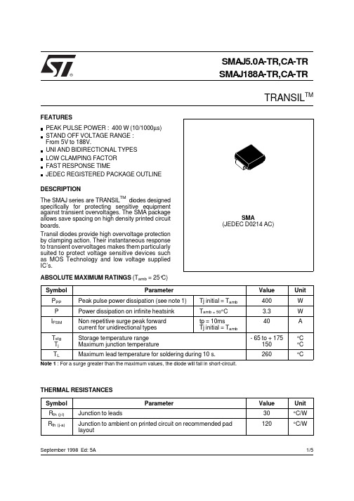
SMAJ5.0A-TR,CA-TR SMAJ188A-TR,CA-TRTRANSIL TM®PEAK PULSE POWER : 400 W (10/1000µs)STAND OFF VOLTAGE RANGE :From 5V to 188V.UNI AND BIDIRECTIONAL TYPES LOW CLAMPING FACTOR FAST RESPONSE TIMEJEDEC REGISTERED PACKAGE OUTLINE FEATURESSMA(JEDEC D0214 AC)Symbol ParameterValue Unit P PP Peak pulse power dissipation (see note 1)Tj initial = T amb 400W P Power dissipation on infinite heatsink T amb = 50°C 3.3W I FSM Non repetitive surge peak forward current for unidirectional types tp = 10msTj initial = T amb40A T stg T j Storage temperature range Maximum junction temperature- 65 to + 175150°C °C T LMaximum lead temperature for soldering during 10 s.260°CNote 1 : For a surge greater than the maximum values, the diode will fail in short-circuit.ABSOLUTE MAXIMUM RATINGS (T amb = 25°C)DESCRIPTIONThe SMAJ series are TRANSIL TM diodes designed specifically for protecting sensitive equipment against transient overvoltages. The SMA package allows save spacing on high density printed circuit boards.Transil diodes provide high overvoltage protection by clamping action. Their instantaneous response to transient overvoltages makes them particularly suited to protect voltage sensitive devices such as MOS Technology and low voltage supplied IC’s.September 1998 Ed: 5A Symbol ParameterValue Unit R th (j-l)Junction to leads30°C/W R th (j-a)Junction to ambient on printed circuit on recommended pad layout120°C/WTHERMAL RESISTANCES 1/5II F V F V CLV BRV RMI PPI RMVSymbol ParameterV RM Stand-off voltage V BR Breakdown voltage V CL Clamping voltage I RM Leakage current @ V RM I PPPeak pulse currentαTVoltage temperature coefficient V FForward voltage dropELECTRICAL CHARACTERISTICS (T amb = 25°C)TypesI RM @ V RM V BR @ I R V CL @ I PP V CL @ I PP αT C maxmin maxmaxmaxtyp note210/1000µs 8/20µs note3note4Unidirectional Mark.Bidirectional Mark. µA V V mA V A V A 10-4/°C pF SMAJ5.0A-TR AE SMAJ5.0CA-TR AA 800 5.0 6.4109.243.513.4174 5.73500SMAJ6.0A-TR DUB SMAJ6.0CA-TR DBB 800 6.0 6.71010.338.813.7170 5.93300SMAJ6.5A-TR DUC SMAJ6.5CA-TR DBC 500 6.57.21011.235.714.5160 6.13100SMAJ8.5A-TR DUH SMAJ8.5CA-TR DBH 108.59.44114.427.718.61247.32000SMAJ10A-TR AX SMAJ10CA-TR AC 51011.111723.521.71067.81550SMAJ12A-TR DUK SMAJ12CA-TR DBK 51213.3119.920.125.3918.31325SMAJ13A-TR BG SMAJ13CA-TR BH 11314.4121.518.627.2858.41200SMAJ15A-TR BM SMAJ15CA-TR AJ 11516.7124.416.432.5718.8975SMAJ18A-TR DUQ SMAJ18CA-TR DBQ 11820129.213.739.3599.2800SMAJ20A-TR DUR SMAJ20CA-TR DBR 12022.2132.412.342.8549.4725SMAJ22A-TR DUS SMAJ22CA-TR DBS 12224.4135.511.248.3489.6625SMAJ24A-TR DUT SMAJ24CA-TR DBT 12426.7138.910.350469.6600SMAJ26A-TR DUU SMAJ26CA-TR DBU 12628.9142.19.553.5439.7575SMAJ28A-TR CG SMAJ28CA-TR CH 12831.1145.48.859399.8510SMAJ30A-TR CK SMAJ30CA-TR CL 13033.3148.48.364.3369.9480SMAJ33A-TR CM SMAJ33CA-TR CN 13336.7153.37.569.73310.0450SMAJ40A-TR DUZ SMAJ40CA-TR DBZ 14044.4164.5 6.2842710.1370SMAJ43A-TR EUA SMAJ43CA-TR EBA 14347.8169.4 5.7912510.2350SMAJ48A-TR CX SMAJ48CA-TR CY 14853.3177.4 5.21002310.3320SMAJ58A-TR EUF SMAJ58CA-TR EBF 15864.4193.6 4.31211910.4270SMAJ70A-TR EUI SMAJ70CA-TR EBI 17077.81113 3.51461610.5230SMAJ85A-TR EUL SMAJ85CA-TR EBL 18594.41137 2.91781310.6200SMAJ100A-TR EUN SMAJ100CA-TR EBN 11001111162 2.52121110.7170SMAJ130A-TR EUQ SMAJ130CA-TR EBQ 11301441209 1.9265910.8145SMAJ154A-TR EUT SMAJ154CA-TR EBT 11541711246 1.6317710.8125SMAJ170A-TR SR SMAJ170CA-TR SS 11701891275 1.4353 6.510.8120SMAJ188A-TREUV SMAJ188CA-TR EBV 11882091328 1.4388610.8110Note 2 :Pulse test : t p < 50 ms.Note 3 :∆V BR = αT * (T amb - 25) * V BR (25°C).Note 4 :V R = 0 V, F = 1 MHz. For bidirectional types,capacitance value is divided by 2.10s1000s%I PP 50tPULSE WAVEFORM 10/1000s100SMAJxxxA-TR, CA-TR2/52550751001251501750.00.10.20.30.40.50.60.70.80.91.01.1Ppp[Tj initial]/Ppp[Tj initial=25°C]Tj initial(°C)Fig 1: Peak power dissipation versus initial junction temperature.0.010.101.0010.0010010005000Ppp(W)tp(ms)Fig 2: Peak pulse power versus exponential pulse duration (Tj initial=25°C).1101005000.11.010.0100.0200.0Ipp(A)tp=20µstp=1ms SMAJ5.0A,CASMAJ188A,CASMAJ58A,CASMAJ26A,CASMAJ13A,CAV (V)CL Fig 3: Clamping voltage versus peak pulse current (Tj initial=25°C)Exponential waveform tp=20µs & tp=1ms.1101002001010010005000C(pF)F=1MHzSMAJ5.0ASMAJ188ASMAJ58ASMAJ26A SMAJ13A V (V)R Fig 4-1: Capacitance versus reverse applied voltage (typical values) (SMAJxxA).11010020011010010002000F=1MHzSMAJ5.0CA SMAJ188CASMAJ58CA SMAJ26CA SMAJ13CAC(pF)V (V)R Fig 4-2: Capacitance versus reverse applied voltage (typical values) (SMAJxxCA).SMAJxxxA-TR, CA-TR3/50.40.50.60.70.80.9 1.0 1.1 1.2 1.3 1.40.010.101.0010.00I (A)FM Tj=25°CTj=125°CV (V)FM Fig 5: Peak forward voltage drop versus peak forward current (typical values).1E-21E-11E+01E+11E+25E+20.010.101.00Zth(j-a)/Rth(j-a)tp(s)Fig 6: Relative variation of thermal impedance junction to ambient versus pulse duration.12345405060708090100110120130140Rth(j-a) (°C/W)S(Cu)(cm²)Fig 7: Thermal resistance junction to ambient versus copper surface under each lead (printed circuit board FR4 e(Cu)=35µm).2550751001251501E-11E+01E+11E+21E+32E+3I [Tj] / I [Tj=25°C]R R V < 8.5VBR Tj(°C)V 8.5VBR ≥Fig 8: Relative variation of leakage current versus junction temperature.SMAJxxxA-TR, CA-TR4/5REF.DIMENSIONSMillimeters Inches Min.Max.Min.Max.A11.902.700.0750.106A20.050.200.0020.008b1.25 1.650.0490.065c 0.150.410.0060.016E4.805.600.1890.220E13.954.600.1560.181D 2.25 2.950.0890.116L0.751.600.0300.063Information furnished is believed to be accurate and reliable. However, STMicroelectronics assumes no responsibility for the consequences of use of such information nor for any infringement of patents or other rights of third parties which may result from its use. No license is granted by implication or otherwise under any patent or patent rights of STMicroelectronics.Specifications mentioned in this publication are subject to change without notice. This publication supersedes and replaces all information previously supplied.STMicroelectronics products are not authorized for use as critical components in life support devices or systems without express written approval of STMicroelectronics.The ST logo is a registered trademark of STMicroelectronics © 1998 STMicroelectronics - Printed in Italy - All rights reserved.STMicroelectronics GROUP OF COMPANIESAustralia - Brazil - Canada - China - France - Germany - Italy - Japan - Korea - Malaysia - Malta - Mexico - Morocco -The Netherlands - Singapore - Spain - Sweden - Switzerland - Taiwan - Thailand - United Kingdom - U.S.A.Packaging : standard packaging is in tape and reel.PACKAGE MECHANICAL DATA SMA (Plastic)ECLE1DA1A2bMARKING : Logo, Date Code, Type Code, Cathode Band (for unidirectional types only).FOOTPRINT DIMENSIONS (Millimeter)SMA Plastic.2.40 1.651.45 1.45Weight = 0.068 gORDER CODESM A J 85 C A - TRBIDIRECTIONALNo suffix : UnidirectionalSURFACE MOUNTSTAND OFF VOLTAGE400 WATTSTAPE & REEL SMAJxxxA-TR, CA-TR5/5。

What ’s In The BoxPlease inspect the contents of your shipped package to ensure you have received everything that is listed below.A s s e m b ly M a n u a lAll rights reserved. No part of this document may be reproduced, stored in a retrieval system, or transmitted by any form or by any means,electronic, mechanical, photo -copying, recording, or otherwise, except as may be expressly permitted by the applicable copyrightstatutes or in writing by the Publisher.Fly -master 13ft Telescopic Carbon FiberJib Crane (JB -FLMS -01)Fly -Master Jib for Zhiyun Crane -2Top Cable WireCable Guide RodWeight Rod∙Loosenthe bottomclamp ofthe fluid head (Not Included) and mount it on the stand.Fly Master Jib Setup∙ Then properly tighten the bottom clamp onthe 100mm bowlstand(Not Included), asshown in the image.NOTE: It comes with a tripod mount with 1/4"-20 and 3/8"-16 threads on the bottom to mountit on the fluid head.∙ Now remove the fluid head plate by pressing the lock lever.∙ Attach the plate to the Fly -master Jib andsecurely tighten it, matching the threads, withthe help of a screwdriver.NOTE: It extended when not in use atcongested shoot sites. Just slide in or out whenrequired.∙ Now mount the Fly -master Jib on top of thefluid head and properly tighten it with thelocking lever.∙ Loosentheknob andincrease theheight of the jib as shown in the image.∙ Attach the Gimbal mounting adapter to theGimbal (Not Included) and properly tightenusing a screwdriver.NOTE: Any other gimbal with a handle,featuring a 1/4"-20 or 3/8" -16 threaded hole atits bottom, can be attached.NOTE: You can increase the lengths of jib asper requirement.∙ Loosen the ratchet knob and open the clamp.∙ Then remove the Gimbal mounting adapter,as shown in the image.∙ Attach the Gimbal (Not Included) to the clampand properly tighten it via the knob.Gimbal Setup∙ Then properly tighten the knob.NOTE: High -grade Aluminum constructedclamps at each section ’s end promise a strongclamping force.∙ Loosen the knob and insert the weight rod.∙ Properly tighten the knob.NOTE: Provided highly robust weight rodsupports universal weight plates with a 25mmhole diameter.∙ Loosen the clamp ’s knob and rotate theclamp.∙ Insert weight (Not Included) according toyour requirement.Inserting weight rod in Fly master jibNOTE: It ’s compatible with Zhiyun Crane -2 &other hand -held gimbals with 1/4” or 3/8”Mounting threads.∙ Now loosen the clamp's knob and rotatethe clamp.∙ Now, properly tighten the knob and insert thecable guide rod. ∙ Then insert the top cable wire into the rod, asshown in the image.NOTE: Set the Cable Guide rods ’s positionaccording to your requirement.∙ Similarly, insert the second end of the wireinto the clamp, as shown in the imageNOTE: It facilitates convenient underslung &over -slung operations for various shotrequirements.∙ Properly attach the first end of the top cablewire to the clamp.Attaching Top cable wireNOTE:Compatible gimbals- Zhiyun -TechCrane -2 Gimbal (Direct) Single Handle Gimbalswith 1/4"-20 & 3/8"-16 Mounting Threads.∙Then properly tighten with the help of theknob.NOTE: Tripod mount also has a total of three1/4"-20 threaded holes on the sides to attachmonitors & other accessories. LCD Monitor SetupMaximum Extandable Length of Fly Master JibNOTE: Fully extended length=13ft. & Length of 1st 3 each section =3ft. & length of last section=4ft.∙Properly match the threads of the LCD (NotIncluded) and mount the LCD, as shown in theimage.YOUR PROAIM FLY-MASTER TELESCOPIC CARBON FIBER JIB CRANEALL DRESSED UP AND READY TO GO!(SHOWN WITH OPTIONAL ACCESSORIES)Warranty: We offer one year warranty for our products from date of purchase. Within this period of time, we will repair it without charge for labor or parts. Warranty doesn’t cover transportation costs nor does it cover a product subjected to misuse or accidental damage. Warranty repairs are subjected to inspection and evaluation by us.Liability: We are not liable for damage caused by products that we do not supply or from mishandling in transit, accident, misuse, neglect, lack of care of the product, or service by anyone other than our company. Contact Us: In case of any kind of dissatisfaction, please Contact us immediately and we promise our ut-most support and care until you use our product.。
SMAJ5.0(C)A - SMAJ170(C)A 400W SURFACE MOUNT TRANSIENT VOLTAGE
SUPPRESSOR
Features
Maximum Ratings@ T A= 25°C unless otherwise specified
·400W Peak Pulse Power Dissipation
·Glass Passivated Die Construction
·Uni- and Bi-Directional Versions Available
·Excellent Clamping Capability
·Fast Response Time
·Lead Free Finish/RoHS Compliant (Note 4)
Mechanical Data
·Case: SMA
·Case Material: Molded Plastic. UL Flammability
Classification Rating 94V-0
·Moisture Sensitivity: Level 1 per J-STD-020C
·Terminals:Lead Free Plating (Matte Tin Finish).
Solderable per MIL-STD-202, Method 208
·Polarity Indicator: Cathode Band (Note: Bi-directional
devices have no polarity indicator.)
·Marking: Date Code and Marking Code See Page 4
·Weight: 0.064 grams (approximate)
Notes: 1. Valid provided that terminals are kept at ambient temperature.
2. Measured with 8.3ms single half sine-wave. Duty cycle = 4 pulses per minute maximum.
3. Unidirectional units only.
4.RoHS revision 13.2.2003. Glass and High Temperature Solder Exemptions Applied, see EU Directive Annex Notes 5 and 7.
Notes: 5. Suffix C denotes Bi-directional device.
6.V BR measured with I T current pulse = 300m s
7. For Bi-Directional devices having V RWM of 10V and under, the I R is doubled.
10
100
1000
10000
1
10
100
1000
C ,J U N C T I O N C A P A C I T A N C E (p F )
T V ,STANDOFF VOLTAGE (V)Fig.2Typical Total Capacitance
WM
25
50
75
100125150175200
100
75
50
25
T ,AMBIENT TEMPERATURE (C)
Fig.1Pulse Derating Curve
A °P E A K P U L S E D E R A T I N G I N %O F P E A K P O W E R O R C U R R E N T
0123
I ,P E A K P U L S E C U R R E N T (%I )
P p p
t,TIME (ms)
Fig.4Pulse Waveform
0.1
1.0
0.1
10
100
1.0
10
1000
10000
P ,P E A K P U L S E P O W E R (k W )
d 100
0.0
0.2
0.4
0.6
25
50
75100125150175200
P M S T E A D Y S T A T E P O W E R D I S S I P A T I O N (W )
(A V ),T ,LEAD TEMPERATURE (C)
Fig.6Steady State Power Derating Curve
L °0.8
1.0
60
50
40
30
20
10
2510P E A K F O R W A R D S U R G E C U R R E N T ,(A )
NUMBER OF CYCLES AT 60Hz
Fig.5Maximum Non-Repetitive Surge Current
2050100
1
XX =Product type marking code (See Page 2)
=Manufacturers’code marking YWW =Date code marking
Y =Last digit of year ex:2for 2002WW =Week code 01to
52
Marking Information
Ordering Information
Notes: 8. For Packaging Details, go to our website at /datasheets/ap02007.pdf.*x = Device Voltage, e.g., SMCJ170A-13-F.Example: SMAJ170A-13-F.
(Note 8)。