STE38NB50F中文资料
- 格式:pdf
- 大小:91.86 KB
- 文档页数:8
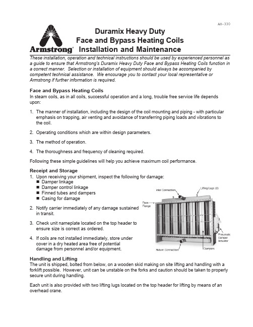
AH-330These installation, operation and technical instructions should be used by experienced personnel as a guide to ensure that Armstrong's Duramix Heavy Duty Face and Bypass Heating Coils function in a correct manner. Selection or installation of equipment should always be accompanied by competent technical assistance. We encourage you to contact your local representative or Armstrong if further information is required.Face and Bypass Heating CoilsIn steam coils, as in all coils, successful operation and a long, trouble free service life depends upon:1.The manner of installation, including the design of the coil mounting and piping - with particular emphasis on trapping, air venting and avoidance of transferring piping loads and vibrations to the coil.2.Operating conditions which are within design parameters.3.The method of operation.4.The thoroughness and frequency of cleaning required.Following these simple guidelines will help you achieve maximum coil performance.Receipt and Storage1.Upon receiving your shipment, inspect the following for damage:Damper linkageDamper control linkageFinned tubes and dampersCasing for damage2.Notify carrier immediately of any damage sustainedin transit.3.Check unit nameplate located on the top header toensure size is correct as ordered.4.If coils are not installed immediately, store undercover in a dry heated area free of potentialdamage from personnel and/or equipment.Handling and LiftingThe unit is shipped, bolted from below, on a wooden skid making on site lifting and handling with a forklift possible. However, unit can be unstable on the forks and caution should be taken to properly secure unit during handling.Each unit is also provided with two lifting lugs located on the top header for lifting by means of an overhead crane.Duramix Heavy Duty Face and Bypass Heating CoilsInstallation and MaintenanceInstallation and Mounting1.Remove shipping bolts from the wooden skid and the damper protective wooden sheets.2.Install the unit with the tubes vertical only. Do not arrange with tubes horizontal.3.The unit must be set "level" for proper drainage.4.Provide a minimum 36" space down stream of the unit for mixing of by-passed and heated air.5.Support the unit by resting the casing directly on the floor or other support structure.6.Support unit and piping individually to prevent undue strains on the steam and condensateconnections.7.Ductwork can be attached to the unit by bolting the casing perimeter face flanges. The casingflanges must not be used to support the ductwork.Piping1.Steam and condensate pipes should be the same size as coil connections. Maintain connectionsize from the coil back to the steam main and from the coil to the steam trap takeoff.2.The return header must be free to float and must not be restricted by condensate return piping.Use flexible connections for freedom of movement.3.Install strainers with blowdown valves before all control valves and traps.4.Install a drip trap prior to the heating unit to prevent the introduction of condensate.5.Install a vacuum breaker in the steam line piping prior to the unit. Also, install a vacuum breakeron the downstream side of the unit for better drainage during shutdown.6.Wherever possible, steam should enter the coil vertically rather than from the side.7.Vent non-condensable gases to ensure maximum heat transfer and minimum internal corrosion.Venting can be with a fixed orifice bleed, independent thermostatic vent or by using a float and thermostatic steam trap.e only traps such as the inverted bucket or float and thermostatic which drain continuously.See Table on page 3 for steam trap selection. Consult you Armstrong Representative if you need assistance.9.Install a dirt pocket prior to the steam trap. You may also install a gate valve at the bottom of thedirt pocket to facilitate drainage during shutdown periods.10.Size traps to handle the maximum calculated load using a service factor of 3. Consult yourArmstrong Representative if you need assistance.11.If the condensate return system is overhead contact your local Armstrong Representative.12.Install a 90° elbow (full size of header) on the return header connection directed downward forconnection to condensate piping. Install a flexible connector in the first horizontal run closest to coil return header.2Piping practices for Duramix steam heating coils are shown below.Notes:1.24" minimum if safety drain is used.2.Safety drain is used if pressurized or overhead. Armstrong's pumping traps orPosi-Pressure Control system provides additional protection.3.The air vent may be either an orifice bleed or thermostatically operated element.4.The main trap may be either an Inverted Bucket or a Float & Thermostatic type dependingupon the service conditions. See Table below for steam trap recommendations. Note:Inverted bucket steam trap required with Posi-Pressure Control system.5.Overhead condensate return option.Control Arrangement and AdjustmentThe required leaving air temperature from the unit is controlled by automatic positioning of the face and by-pass dampers via a pneumatic actuator in response to the signal produced by a thermostat located in the downstream ductwork. The temperature sensing element shall be placed not closer than 36" from the face of the unit. This sensing element must be positioned in the center of the face area, horizontally across both face and bypass sections of the unit.Duramix units are supplied from the factory complete with a standard pneumatic damper actuator, and a damping mechanism adjusted for the correct stroke. No field adjustments are required.3OperationOnce coils are installed properly, their performance and service life depends on a few simple guidelines for maintenance and operation.1.Clean the piping system by blowing down all strainers prior to start-up.2.On each start-up, feed steam to the coils slowly to avoid thermal shock.3.Make sure the steam has been on for a minimum of 15 minutes prior to starting fans and openingdampers or adjusting thermostats and control air pressure to the units.4.Make sure operating pressure is within design limits.5.To provide maximum freeze protection, maintain a minimum steam pressure of 5 psig to coilsexposed to air temperature below 40°F (5°C).Shut-DownDrain condensate during shutdown to prevent internal corrosion.1.Shut off the airflow (especially with subfreezing entering air).2.Shut off steam.3.As soon as possible, open drip leg in return main line and allow condensate to drain. If safetydrain is used, the coil will drain automatically.MaintenanceInspect and clean coils periodically to maintain adequate airflow and to keep fan loading at design. Loose nuts, bolts and screws should be tightened. The damper control linkage and the damper control arms should be inspected for wear and replaced if worn. Uneven heating as well as freezing failure can be expected in the coil if worn damper control arms are not replaced.Armstrong-Hunt, Inc., 648 Moeller, Granby, Quebec, Canada J2G 8N1 - Ph: (450) 378-2655 Fax: (450) 375-3787AH-330 2/02 Printed in U.S.A.。

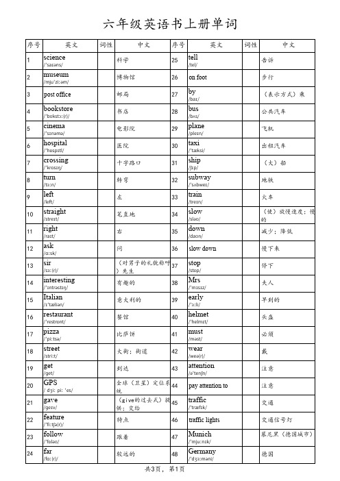
六年级英语书上册单词序号 英文词性 中文序号 英文词性 中文1science/ˈsaɪəns/科学25tell/tel/告诉2museum/mjuˈziːəm/博物馆26on foot步行3post office邮局27by/baɪ/(表示方式)乘4bookstore/ˈbʊkstɔː(r)/书店28bus/bʌs/公共汽车5cinema/ˈsɪnəmə/电影院29plane/pleɪn/飞机6hospital/ˈhɒspɪtl/医院30taxi/ˈtæksi/出租汽车7crossing/ˈkrɒsɪŋ/十字路口31ship/ʃɪp/(大)船8turn/tɜːn/转弯32subway/ˈsʌbweɪ/地铁9left/left/左33train/treɪn/火车10straight/streɪt/笔直地34slow/sləʊ/(使)放慢速度;慢的11right/raɪt/右35down/daʊn/减少;降低12ask/ɑːsk/问36slow down慢下来13sir/sɜː(r)/(对男子的礼貌称呼)先生37stop/stɒp/停下14interesting/ˈɪntrəstɪŋ/有趣的38Mrs/ˈmɪsɪz/夫人15Italian/ɪˈtæliən/意大利的39early/ˈɜːli/早到的16restaurant/ˈrestrɒnt/餐馆40helmet/ˈhelmɪt/头盔17pizza/ˈpiːtsə/比萨饼41must/məst/必须18street/striːt/大街;街道42wear/weə(r)/戴19get/ɡet/到达43attention/əˈtenʃn/注意20GPS/ˌdʒiː piː ˈes/全球(卫星)定位系统44pay attention to注意21gave/ɡeɪv/(give的过去式)提供;交给45traffic/ˈtræfɪk/交通22feature/ˈfiːtʃə(r)/特点46traffic lights交通信号灯23follow/ˈfɒləʊ/跟着47Munich/ˈmjuːnɪk/慕尼黑(德国城市)24far/fɑː(r)/较远的48Germany/ˈdʒɜːməni/德国49Alaska/əˈlæskə/阿拉斯加州(美国州名)74half/hɑːf/一半50sled/sled/雪橇75price/praɪs/价格51fast/fɑːst/快的76Mid-Autumn Festival中秋节52ferry/ˈferi/轮渡77together/təˈɡeðə(r)/一起53Papa Westray帕帕韦斯特雷岛78get together聚会54Scotland/ˈskɒtlənd/苏格兰79mooncake/ˈmu:nkeɪk/月饼55visit/ˈvɪzɪt/拜访80poem/ˈpəʊɪm/诗56film/fɪlm/电影81moon/muːn/月亮57see a film看电影82studies/ˈstʌdiz/(study的第三人称单数形式)学习58trip/trɪp/旅行83puzzle/ˈpʌzl/谜59take a trip去旅行84hiking/ˈhaɪkɪŋ/远足60supermarket/ˈsuːpəmɑːkɪt/超市85pen pal笔友61evening/ˈiːvnɪŋ/晚上;傍晚86hobby/ˈhɒbi/业余爱好62tonight/təˈnaɪt/在今晚87jasmine/ˈdʒæzmɪn/茉莉63tomorrow/təˈmɒrəʊ/明天88idea/aɪˈdɪə/想法;主意64next week下周89Canberra/ˈkænbərə/堪培拉(澳大利亚首都)65dictionary/ˈdɪkʃənri/词典90amazing/əˈmeɪzɪŋ/令人惊奇的66comic/ˈkɒmɪk/滑稽的91goal/ɡəʊl/射门67comic book(儿童的)连环画册92join/dʒɔɪn/加入68word/wɜːd/单词93club/klʌb/俱乐部69word book单词书94share/ʃeə(r)/分享70postcard/ˈpəʊstkɑːd/明信片95factory/ˈfæktri/工厂71lesson/ˈlesn/课96worker/ˈwɜːkə(r)/工人72space/speɪs/太空97postman/ˈpəʊstmən/邮递员73travel/ˈtrævl/(尤指长途)旅行98businessman/ˈbɪznəsmæn/商人;企业家99police officer警察124deep/diːp/深的100fisherman/ˈfɪʃəmən/渔民125breath/breθ/呼吸101scientist/ˈsaɪəntɪst/科学家126take a deep breath深深吸一口气102pilot/ˈpaɪlət/飞行员127count/kaʊnt/数数103coach/kəʊtʃ/教练128count to ten数到十104country/ˈkʌntri/国家129chase/tʃeɪs/追赶105head teacher校长130mice/maɪs/(mouse的复数)老鼠106sea/siː/大海131bad/bæd/邪恶的;坏的107stay/steɪ/保持132hurt/hɜːt/(使)受伤108university/ˌjuːnɪˈvɜːsəti/大学133ill/ɪl/有病;不舒服109gym/dʒɪm/体育馆134wrong/rɒŋ/有毛病110if/ɪf/如果135should/ʃəd/应该111reporter/rɪˈpɔːtə(r)/记者136feel/fiːl/觉得;感到112use/juːz/使用137well/wel/健康;身体好113type/taɪp/打字138sit/sɪt/坐114quickly/ˈkwɪkli/迅速地139grass/ɡrɑːs/草坪115secretary/ˈsekrətri/秘书140hear/hɪə(r)/听见116angry/ˈæŋɡri/生气的141ant/ænt/蚂蚁117afraid/əˈfreɪd/害怕142worry/ˈwʌri/担心;担忧118sad/sæd/难过的143stuck/stʌk/陷住;无法移动119worried/ˈwʌrid/担心的;发愁的144mud/mʌd/泥120happy/ˈhæpi/高兴的145pull/pʊl/拉;拽121see a doctor看病146everyone/ˈevriwʌn/每人122wear/weə(r)/穿147六年级英语书下册单词序号 英文 中文序号 英文 中文1younger/ˈjʌŋɡə/(young的比较级)更年轻的25watched/wɑːtʃt/(watch的过去式)看2older/ˈəʊldə/(old的比较级)更年长的26had/həd/(have的过去式)患病;得病3taller/ˈtɔ:lə(r)/(tall的比较级)更高的27had a cold感冒4shorter/ʃɔːtə/(short的比较级)更矮的;更短的28slept/slept/(sleep的过去式)睡觉5longer/lɒŋɡə(r)/(long的比较级)更长的29read/riːd/(read的过去式)读6thinner/ˈθɪnə(r)/(thin的比较级)更瘦的30saw/sɔː/(see的过去式)看见7heavier/ˈhevɪə/(heavy比较级)更重的31last/lɑːst/最近的;上一个的8bigger/bɪgə(r)/(big的比较级)更大的32yesterday/ˈjestədeɪ/昨天9smaller/smɔ:lə(r)/(small的比较级)更小的33before/bɪˈfɔː(r)/在……之前10stronger/strɒŋgə(r)/(strong的比较级)更强壮的34drank/dræŋk/(drink的过去式)喝11dinosaur/ˈdaɪnəsɔː(r)/恐龙35show/ʃəʊ/演出12hall/hɔːl/大厅36magazine/ˌmæɡəˈziːn/杂志13metre/ˈmiːtə(r)/米37better/ˈbetə(r)/(well的比较级)更好的14than/ðən/比38faster/fɑ:stə(r)/(fast的比较级)更快的15both/bəʊθ/两个都39hotel/həʊˈtel/旅馆16kilogram/ˈkɪləɡræm/千克;公斤40fixed/fɪkst/(fix的过去式)修理17countryside/ˈkʌntrisaɪd/乡村41broken/ˈbrəʊkən/破损的18lower/ˈləʊə(r)/(low的比较级)更低地42lamp/læmp/台灯19shadow/ˈʃædəʊ/阴影;影子43loud/laʊd/喧闹的;大声的20smarter/ˈsmɑ:tə/(smart的比较级)更聪明的44enjoy/ɪnˈdʒɔɪ/享受……乐趣;喜爱21become/bɪˈkʌm/开始变得;变成45stay/steɪ/暂住;逗留22cleaned/kliːnd/(clean的过去式)打扫46went/went/(go的过去式)去23stayed/steɪd/(stay的过去式)停留;待47camp/kæmp/野营24washed/wɒʃt/(wash的过去式)洗48went camping(尤指在假日)野营序号 英文 中文序号 英文 中文49fish/fɪʃ/钓鱼;捕鱼71grass/ɡrɑːs/草坪50went fishing去钓鱼72gym/dʒɪm/体育馆51rode/rəʊd/(ride的过去式)骑(马;自行车)73ago/əˈɡəʊ/以前52hurt/hɜːt/(hurt的过去式)(使)受伤74cycling/ˈsaɪklɪŋ/骑自行车运动(或活动)53ate/et/(eat的过去式)吃75go cycling去骑自行车54took/tʊk/(take的过去式)拍照76ice-skate/ˈaɪs skeɪt/滑冰55took pictures照相77badminton/ˈbædmɪntən/羽毛球运动56bought/bɔːt/(buy的过去式)买78star/stɑː(r)/星57gift/ɡɪft/礼物79easy/ˈiːzi/容易的58fell/fel/(fall的过去式)摔倒80look up(在词典中或通过电脑)查阅59off/ɒf/从(某处)落下81Internet/ˈɪntənet/互联网60Labour Day劳动节82different/ˈdɪfrənt/不同的61mule/mjuːl/骡子83active/ˈæktɪv/积极的;活跃的62Turpan吐鲁番84race/reɪs/赛跑63could/kəd/(can的过去式)能85nothing/ˈnʌθɪŋ/没有什么64till/tɪl/直到86thought/θɔːt/(think的过去式)想65beach/biːtʃ/海滩;沙滩87felt/felt/(feel的过去式)感觉66basket/ˈbɑːskɪt/篮;筐88cheetah/ˈtʃiːtə/猎豹67part/pɑːt/角色89trip/trɪp/绊倒68licked/lɪk/(lick的过去式)舔90woke/wəʊk/(wake的过去式)醒69laughed/lɑːft/(laugh的过去式)笑91dream/driːm/梦70dining hall饭厅92。
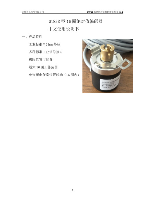
STM38型16圈绝对值编码器中文使用说明书一、产品特性工业标准Φ38mm外径多种标准工业信号接口极限位置可配置最大16圈工作范围允许断电任意位置转动(16圈内)二、产品尺寸a:半中空轴输出b、实心轴输出三、参数规格四、命名规则和线定义1、引出线的颜色定义棕• VDD绿• GND黑• RS485• 输出A• 白• RS485• 输出B•五、通讯协议1)编码器工作模式:从机模式。
当编码器工作于从机模式时,外部设备(如单片机、PC机或PLC设备等,后文统称为外部设备)发送读取命令,编码器回复当前数值。
2)编码器和外部设备采用RS485标准的数据链路层传输数据,数据通讯格式为:19200bit/s;数据位8位、停止位1位、无奇偶校验位。
3)编码器对外部设备发送的错误数据帧,或者检测出通讯数据出现错误,编码器均不进行任何应答标准MODBUS RTU从机,通讯数据帧结构如下:5.1 主机读取编码器数值格式主机发送读命令编码器回复读命令5.2 主机修改编码器站号数据格式主机发送写命令编码器回复写命令编码器位置数据地址为0站号址为1实例:读取读取站号1的编码器数据:主机发送: 01 03 00 00 00 01 84 0A 84 0A为校验码CRC1 CRC2编码器回复:01 03 02 3D 26 CRC1 CRC2说明回复编码器位置为3D26 转换十进制为15654 --编码器的当前位置将站号1的编码器改为站号2:主机发送: 01 06 00 01 00 02 59 CB 59 CB为校验码CRC1 CRC2编码器回复:01 06 00 01 00 02 CRC1 CRC2备注:回复回来的编码器数据是十六进制数据,需要转换成10进制,才是编码六、使用环境·不得在具有点火性、爆发性气体的环境下使用。
·请勿在有化学品飞溅的场所中进行使用或保存,否则可能因内部回路断线或短路引起破损、烧毁。
·请不要让负载短路,否则会发生破裂或烧坏的可能。

Fluid Cooling Industrial AO SeriesPerformance Notes▪Interchange for Young OCH ▪Adjustable louvers (manual) ▪Medium flow rates ▪Moderate heat removal ▪One or two passMaterialsTubes Copper Fins Aluminum Turbulators SteelFan Blade Aluminum with steel hub Fan Guard Zinc plated steel Cabinet Steel with powder coat finish Manifolds Steel Connections Steel RatingsMaximum Operating Pressure 300 PSI Test Pressure 300 PSIMaximum Operating Temperature 400°FNet Weight (LBS)Model WeightAO-5 47AO-10 62AO-15 72AO-20 86AO-25 120AO-30 135AO-35 160AO-40 185OPTIONSInternal pressure bypass Foot bracketsSAE & metric connectionsCorrosive resistant marine coatingOne Pass with BypassTwo Pass with BypassOne Pass (Medium to High Oil Flows)ModelFlow Range GPM (USA)AOR - 5-1 2 - 80AOR - 10-1 3 - 80AOR - 15-1 4 - 80AOR - 20-1 5 - 80AOR - 25-1 6 - 100AOR - 30-1 7 - 100AOR - 35-1 8 - 112AOR - 40-19 - 118Two Pass (Low to Medium Oil Flows)ModelFlow Range GPM (USA)AOR - 5-2 2 - 25AOR - 10-2 2 - 30AOR - 15-2 2 - 30AOR - 20-2 2 - 40AOR - 25-2 2 - 40AOR - 30-2 2 - 40AOR - 35-2 3 - 40AOR - 40-24 - 40ModelSeries AOAOR - Internal pressure bypass includedFoot Mounted Brackets Blank - No Brackets FB - Foot BracketsSpecify Motor Required Single PhaseSingle Phase Expl. ProofThree Phase Three Phase 575 Volt Three Phase Expl. Proof–Connection Type Blank - NPT S - SAE M - MetricNumber of Passes*Blank - No Bypass 1 - One Pass 2 - Two PassBypass Setting*Blank - No Bypass30-30 PSI 60 - 60 PSI––––*ADD FOR AOR MODELS ONLY: Bypass setting & number of passesThis is a partial flow pressure bypass only. It is not designed to be a full flow system bypass.Model Size Selected–How to Order0916t e s y o f C M A /F l o d y n e /H y d r a d y n e ▪ M o t i o n C o n t r o l ▪ H y d r a u l i c ▪ P n e u m a t i c ▪ E l e c t r i c a l ▪ M e c h a n i c a l ▪ (800) 426-5480 ▪ w w w .c m a f h .c o mSpecificationsExplosion Proof Motors (Class I GP.D & Class II GP.F, G)*575 VoltCaution: Do not over oil or over grease. Ball bearings – No grease needed at start up. Grease as follows:5,000 Hours/Year5 Year Grease Interval Continuous — Normal Applications2 Years Seasonal Service — Motor is idle for 6 months or more1 Year C ontinuous —High ambients, dirty or moist locations, high vibration6 MonthsPublished electrical ratings are approximate, and may vary because of motor brand. Actual ratings are on motor nameplate.* C atalog dB(A) sound levels are at seven (7) feet. dB(A) sound levels increase by six (6) dB(A) for halving this distance and decrease by six (6) dB(A) for doubling this distance.Published electrical ratings are approximate, and may vary because of motor brand. Actual ratings are on motor nameplate.* C atalog dB(A) sound levels are at seven (7) feet. dB(A) sound levels increase by six (6) dB(A) for halving this distance and decrease by six (6) dB(A) for doubling this distance.t e s y o f C M A /F l o d y n e /H y d r a d y n e ▪ M o t i o n C o n t r o l ▪ H y d r a u l i c ▪ P n e u m a t i c ▪ E l e c t r i c a l ▪ M e c h a n i c a l ▪ (800) 426-5480 ▪ w w w .c m a f h .c o mFan Rotation Clockwise/Facing Motor ShaftPiping Diagram* S ee dimension chart for NPT or optional internal SAEconnection size.One Pass Without BypassTwo Pass Without Bypass1/2-13 UNC-2BAO 35 & 40(Top & Bottom)4 PlacesAIRFLOWNOTE: MOTOR MOUNTING BRACKET ONAO-5 & AO-10 IS ROTATED 90°THJBAG2.316.19M3 PlacesDFLKCNP1.75 1.62E Approx.10.36C V Viscosity CorrectiontesyofCMA/Flodyne/Hydradyne▪MotionControl▪Hydraulic▪Pneumatic▪Electrical▪Mechanical▪(8)426-548▪w wOne Pass OilTwo Pass OilOil Flow - GPMH o r s e p o w e r R e m o v e d I n C o o l e rOil Flow - GPMH o r s e p o w e r R e m o v e d I n C o o l e r12345678910203040Performance Curves are based on 50SSU oil leaving the cooler 40°F higher than the ambient air temperature used for cooling. This is also referred to as a 40°F approach temperature.STEP 1 D etermine the Heat Load. This will vary with different systems, buttypically coolers are sized to remove 25 to 50% of the input nameplatehorsepower.(Example: 100 HP Power Unit x .33 = 33 HP Heat load.) If BTU/HR is known: HP = BTU/HR 2545STEP 2 D etermine Approach Temperature. Desired oil leaving cooler°F – Ambient air temp. °F = Actual ApproachSTEP 3 D etermine Curve Horsepower Heat Load. Enter the informationfrom above:Horsepower heat load x 40 x Cv = Curve HorsepowerActual ApproachSTEP 4 E nter curves at oil flow through cooler and curve horsepower.Any curve above the intersecting point will work.STEP 5 D etermine Oil Pressure Drop from Curves:l = 5 PSI n = 10 PSI s = 14 PSI ✚ = 20 PSI Multiply pressure drop from curve by correction factor found in oil P correction curve.Desired Reservoir TemperatureReturn Line Cooling: Desired temperature is the oil temperature leaving the cooler. This will be the same temperature that will be found in the reservoir.Off-Line Recirculation Cooling Loop: Desired temperature is the oil temperature entering the cooler. In this case, the oil temperature change must be determined so that the actual oil leaving temperature can be found. Calculate the oil temperature change (oil T) with this formula: Oil T = (BTU’s/HR) / (GPM Oil Flow x 210).To calculate the oil leaving temperature from the cooler, use this formula: Oil Leaving Temp. = Oil Entering Temp – Oil T.This formula may also be used in any application where the only temperature available is the entering oil temperature.Oil Pressure Drop: Most systems can tolerate a pressure drop through the heat exchanger of 20 to 30 PSI. Excessive pressure drop should be avoided. Care should be taken to limit pressure drop to 5 PSI or less for case drain applications where high back pressure may damage the pump shaft seals.Oil TemperatureTypical operating temperature ranges are:Hydraulic Motor Oil 110°- 130°F Hydrostatic Drive Oil 130°- 180°F Bearing Lube Oil 120°- 160°F Lube Oil Circuits 110°- 130°F5010000200350051234O i l P M u l t i p l i e rOil Viscosity - SSUOil P Correction Curve400Oil Pressure Correctiont e s y o f C M A /F l o d y n e /H y d r a d y n e ▪ M o t i o n C o n t r o l ▪ H y d r a u l i c ▪ P n e u m a t i c ▪ E l e c t r i c a l ▪ M e c h a n i c a l ▪ (800) 426-5480 ▪ w w。
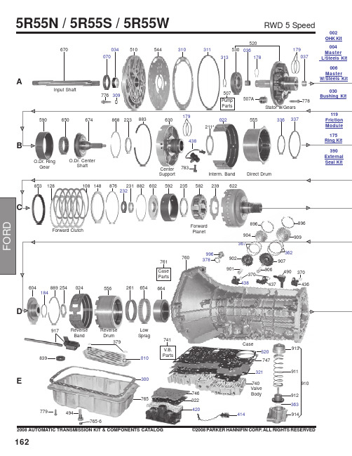
1622008 AUTOMATIC TRANSMISSION KIT & COMPONENTS CATALOG ©2008 PARKER HANNIFIN CORP. ALL RIGHTS RESERVED3790103008397797405R55N / 5R55S / 5R55WRWD 5 SpeedA544510034070670Input ShaftO.Dr. Ring GearO.Dr. CenterShaft783Center SupportInterm. BandDirect DrumForward ClutchForward PlanetReverse BandReverse DrumLow Sprag310037179520036178530311914363912911913910896904896437490996V.B.Parts741E414494765-6370Case313321320Valve Body917747765746322420002OHK Kit004Master L/Steels Kit 006Master 030External Seal Kit1632008 AUTOMATIC TRANSMISSION KIT & COMPONENTS CATALOG ©2008 PARKER HANNIFIN CORP . ALL RIGHTS RESERVEDRWD 5 Speed5R55N / 5R55S / 5R55W862981971961560961971985879565126106146861*229964974877564285872962972104124552894Intermediate Sprag690074266Park Gear264847Park Pawl Assy995-1995-2995-3995916-2916-3919922915916-2916-3919922916263EDA181554770Ext. Hsg.781493305678Output ShaftO.Dr. Band StrutInterm. Band Strut268841Internal Linkage991-2991-3994799991-4761P-4991072410992Yoke1642008 AUTOMATIC TRANSMISSION KIT & COMPONENTS CATALOG©2008 PARKER HANNIFIN CORP. ALL RIGHTS RESERVED*Prefix Letter ‘T’ denotes Toledo-Trans Kit (TTK) Brand Transmission Kits *Prefix Letter ‘B’ denotes Bryco Brand Transmission Kits002.............T16002AP......Overhaul Kit, 5R55N (With Bonded Pistons) 1999-Up ..............................................................1..........002.............T16002GP......Overhaul Kit, 5R55S/5R55W (With Bonded Pistons) 2002-Up..................................................1..........004.............T16004AP......Master L/Steels Kit, 5R55N (With Bonded Pistons) 1999-Up ....................................................1..........004.............T16004GP......Master L/Steels Kit, 5R55S/5R55W (With Bonded Pistons) 2002-Up .......................................1..........006.............T16006AP......Master W/Steels Kit, 5R55N (With Bonded Pistons) 1999-Up...................................................1..........006.............T16006GP......Master W/Steels Kit, 5R55S/5R55W (With Bonded Pistons) 2002-Up ......................................1..........E300...........45019............Gasket, 5R55N Bottom Pan (Plastic With Silicon Bead) OE Style (With Large Holes) 1999-Up 1..........XW4Z-7A191CA D305...........45097668......Gasket, 5R55N/5R55S/5R55W Extension Housing To Case 1999-Up......................................1..........XW4Z-7086-AA A309..........41217............Gasket, 5R55N/5R55S/5R55W Pump Bolt Washer...................................................................AR ........A310..........45097667......Gasket, 5R55N/5R55S/5R55W Pump 1999-Up..........................................................................1..........XW4Z-7A136AB A311...........1988096........O-Ring, 5R55N/5R55S/5R55W Pump Cover 1999-Up ...............................................................1..........XW4Z-7A248AA A313..........1994747........O-Ring, 5R55N Inner Pump Gear 1999-Up.................................................................................1..........F77Z-7L323AA E320...........45097692......Gasket, 5R55N Valve Body Separator Plate To Case 1999-Up ................................................1..........XW4Z-7D100-BF E320...........45097738......Gasket, 5R55S/5R55W Valve Body Separator Plate To Case (Upper) 2002-Up......................1..........1L2Z-7Z490AB-1A070..........70243V..........Seal, 5R55N/5R55S/5R55W Front (No Flange) (Rubber Coated) 1999-Up ..............................1..........F77Z-7A248AA D072...........70083............Seal, 5R55N Linkage 1999-Up ..................................................................................................1..........D5AZ-7B498A D074...........70283............Seal, 5R55N Rear 2WD 2000-Up ...............................................................................................1..........XW4Z-7052AA D074...........70205............Seal, 5R55S/5R55W Rear (W/Long Boot) 2WD 2002-Up .........................................................1..........F6UZ-7052A D074...........70282............Seal, 5R55S/5R55W Extension Housing 4X4 2002-Up .............................................................1..........1L2Z-7052BA175.............6358..............Ring Kit, 5R55N/5R55S/5R55W (2 Metal 4PTFE 2 Torlon Rings) 1999-Up ...............................1..........A178..........45060279......Ring, 5R55N, 5R55W, 5R55S Pump Support (Lock-Up) 1999-Up .............................................1..........B181...........TAW- 2212....Ring, 5R55N, 5R55W, 5R55S Forward Clutch Cylinder 1999-Up .............................................2..........D184...........45060265......Ring, 5R55N, 5R55W, 5R55S Output Shaft 1999-Up.................................................................1..........A179..........30308............Ring, 5R55N, 5R55W, 5R55S Overdrive Brake Drum 1999-Up.................................................2..........B179...........30308P ..........Ring, 5R55N, 5R55W, 5R55S Direct Clutch (Center Support) 1999-Up Torlon .........................2..........119.............45082NR........Friction Module, 5R55N 1999-Up................................................................................................1..........119.............45082LR........Friction Module, 5R55S/5R55W 2002-Up...................................................................................1..........E010...........45040N ..........Filter, 5R55N (3/8” Tall Pick-up Tube) 1999-Up ..........................................................................1..........XW4Z-7A098BB E010...........F-340.............Filter, 5R55S/5R55W (2 1/4” Tall Pick-Up Tube) 2002-Up..........................................................1..........1L2Z-7A098AC5R55N / 5R55S / 5R55WRWD 5 Speed1652008 AUTOMATIC TRANSMISSION KIT & COMPONENTS CATALOG ©2008 PARKER HANNIFIN CORP. ALL RIGHTS RESERVEDB022...........45090............Band, 5R55N Overdrive/Intermediate (Hi-Energy) 1999-Up......................................................2..........XW4Z-7D034BA 030.............45030G..........Bushing Kit, 5R55N/5R55S/5R55W 1999-Up.............................................................................1..........A034..........31530............Bushing, 5R55N/5R55S/5R55W Pump Cover 1999-Up .............................................................1..........A036..........31531............Bushing, 5R55N/5R55S/5R55W Overdrive Sun Gear 1999-Up................................................1..........A036..........45039............Bushing, 5R55N/5R55S/5R55W Stator (Front) 1999-Up ...........................................................1..........A037..........31532............Bushing, 5R55N/5R55S/5R55W Stator (Rear) 1999-Up............................................................1..........A046..........31533............Bushing, 5R55N/5R55S/5R55W Coast Clutch Drum e 56036A................................................................................................................................1..........B211...........45176A..........Washer, 5R55N/5R55S/5R55W Pump To Coast Clutch Drum .063" (Plastic) 1999-Up.............1..........F7TZ-7D014TA B211...........45176B ..........Washer, 5R55N/5R55S/5R55W Pump To Coast Clutch Drum .071" (Plastic) 1999-Up.............1..........F7TZ-7D014MA B211...........45176C ..........Washer, 5R55N/5R55S/5R55W Pump To Coast Clutch Drum .075" (Plastic) 1999-Up.............1..........F7TZ-7D014NA B211...........45176D ..........Washer, 5R55N/5R55S/5R55W Pump To Coast Clutch Drum .079" (Plastic) 1999-Up.............1..........F7TZ-7D014PA B211...........45176E ..........Washer, 5R55N/5R55S/5R55W Pump To Coast Clutch Drum .083" (Plastic) 1999-Up.............1..........F7TZ-7D014RA B211...........45176F ..........Washer, 5R55N/5R55S/5R55W Pump To Coast Clutch Drum .087" (Plastic) 1999-Up.............1..........F7TZ-7D014SA C232...........45145............Washer, 5R55N/5R55S/5R55W Bearing to Forward Hub (Solid Bronze) 1999-Up .................1..........FOTZ-7D090A D263...........45077............Washer, 5R55N/5R55S/5R55W Parking Gear To Case 1999-Up ..............................................1..........D4ZZ-7B368-AD410...........D56955J ........Switch, 5R55N Neutral Safety (12 Prong Connector) 1999-Up ...............................................1..........XW4Z-7F293AA E922...........33991............Nut, 5R55N/S/W Band 1999-Up .................................................................................................2..........380850-SRWD 5 Speed5R55N / 5R55S / 5R55W。
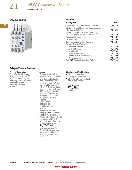
232A Overload—C306DN3BContentsDescription PageContactors—Non-Reversing and Reversing. . . . . .V5-T2-4Starters—Three-Phase Non-Reversing andReversing, Full Voltage . . . . . . . . . . . . . . . . . . . .V5-T2-10Starters—Single-Phase Non-Reversing,Full Voltage, Bi-Metallic Overload . . . . . . . . . . . .V5-T2-15Accessories . . . . . . . . . . . . . . . . . . . . . . . . . . . . . .V5-T2-21Renewal Parts . . . . . . . . . . . . . . . . . . . . . . . . . . . .V5-T2-30Technical Data and Specifications . . . . . . . . . . . . .V5-T2-34Relays—Thermal OverloadProduct Selection . . . . . . . . . . . . . . . . . . . . . . .V5-T2-39Accessories. . . . . . . . . . . . . . . . . . . . . . . . . . . .V5-T2-43Modifications . . . . . . . . . . . . . . . . . . . . . . . . . .V5-T2-43Replacement Parts . . . . . . . . . . . . . . . . . . . . . .V5-T2-44Technical Data and Specifications. . . . . . . . . . .V5-T2-45Dimensions. . . . . . . . . . . . . . . . . . . . . . . . . . . .V5-T2-47C440/XT Electronic Overload Relay. . . . . . . . . . . .V5-T2-48Relays—Thermal OverloadProduct DescriptionC306 Overload Relays aredesigned for use with CEor CN non-reversing andreversing contactors. Foursizes are available foroverload protection upto 144A.Features●Selectable manual orautomatic reset operation●Interchangeable heaterpacks adjustable ±24%to match motor FLA andcalibrated for use with1.0 and 1.15 service factormotors. Heater packs for32A overload relay willmount in 75A overloadrelay—useful in deratingapplications such asjogging●Class 10 or 20heater packs●Load lugs built intorelay base●Bimetallic, ambientcompensated operated.Trip free mechanism●Electrically isolated NO-NCcontacts (pull RESETbutton to test). (Electricalratings see table onPage V5-T2-46)●Overload trip indication●Shrouded or fingerproofterminals to reducepossibility of electricalshockStandards and Certifications●Meets UL 508 single-phasing requirements●UL listed, CSA certified andNEMA complianceV5-T2-38Volume 5—Motor Control and Protection CA08100006E—February Volume 5—Motor Control and Protection CA08100006E—February V5-T2-392Freedom SeriesProduct SelectionC306 Thermal Overload RelaysContactorsStandalone ApplicationsNotes1 NEMA Sizes 5–8 use the 32A overload in conjunction with CTs.2 Series B overload relays have load lugs built into relay base and will only accept Series B heater packs. These relays can be directly attached to contactor or they can be DIN rail or panel mounted using adapter on Page V5-T2-44.3 These relays can be panel mounted only.4 Overload relay assembled with mounting adapter for DIN rail or panel mount.5 Panel mount only.6 NEMA Sizes 5–8 use the 32A overload in conjunction with CTs.NEMA Size Maximum Ampere Rating Number of Poles Open Type NEMA 1 Enclosed Catalog Number Catalog Number 00, 032 23C306DN3B C306DG3B 1, 275 23C306GN3B C306GG3B 3105 33C306KN3—414433C306NN3—5–8 1————NEMA SizeMaximum Ampere Rating Number of Poles Open Type Catalog Number 00, 0, 1 4323C306DT3B 1 4753C306GT3B 3 51053C306KN34 51443C306NN35–8 6———C306DN3BC306GN3BC306DT3BC306GT3B2Heater Pack SelectionHeater packs H2001B toH2017B and H2101B toH2117B are to be used onlywith Series B overload relaysCatalog Numbers C306DN3B(Part No. 10-7016) andC306GN3B (Part No.10-7020). The load lugs arebuilt into the overload relaybase to allow load wiring priorto heater pack installation.The previous heater designhad integral load lugs. TheSeries B heater packs areelectrically equivalent to theprevious heater design.Heaters H2018-3 to H2024-3have not changed.Starters with Series B Overload Relays 1Standard T rip—Class 20 HeaterNotes1 The series of a starter is the last digit of the listed catalog number. Example: AN16DN0AB.2 Heater packs are shipped three to a carton. catalog numbers are for three heater packs.NEMA—AN Type IEC—AE TypeSize Series Size Series00–0C A–F C1–2B G–K B5B G–K B6C G–K B7–8B G–K BOverload Relay SizeMotor Full Load Ampere RatingCatalog Number 2Dial PositionA B CDFor Use with NEMA Sizes 00–0 Series C, NEMA Sizes 1–2 Series B; IEC Sizes A–F Series C, IEC Sizes G–K Series B32A or 75A0.2540.3060.3590.411H2001B-30.3750.4520.5300.607H2002B-30.5600.6760.7910.907H2003B-30.8140.983 1.15 1.32H2004B-31.20 1.45 1.71 1.96H2005B-31.792.16 2.53 2.90H2006B-32.15 2.603.04 3.49H2007B-33.23 3.904.565.23H2008B-34.555.506.457.40H2009B-36.758.179.5811.0H2010B-39.1410.812.414.0H2011B-314.016.919.922.8H2012B-318.722.726.730.7H2013B-323.528.533.538.5H2014B-3For Use with NEMA Size 2, IEC Sizes G–K Only, Series B75A29.034.039.144.1H2015B-339.645.551.557.4H2016B-353.960.967.974.9H2017B-3Heater PackH2001B–H2017BV5-T2-40Volume 5—Motor Control and Protection CA08100006E—February Volume 5—Motor Control and Protection CA08100006E—February V5-T2-412Freedom SeriesStandard T rip—Class 20 Heater, continuedNotes1 Heater packs are shipped three to a carton. catalog numbers are for three heater packs.2 Sizes 5–8 and IEC P–Z use the 32A overload relay with current transformers.Overload Relay SizeMotor Full Load Ampere Rating Catalog Number 1Dial PositionABCDFor Use with NEMA Sizes 3–4, IEC Sizes L–N Only—Series A 105A or 144A8.09.210.311.5H2025-311.412.814.315.7H2026-314.315.717.419.0H2027-318.020.222.324.5H2018-324.627.630.533.4H2019-333.537.541.545.6H2020-345.751.256.762.1H2021-362.269.777.184.6H2022-384.795.0105.0115.0H2023-3106.0118.0131.0144.0H2024-3For Use with Size 5 Starters—Series B and IEC P , R and S with 300/5 CT 32A 249596979H2004B-37287103118H2005B-3107130152174H2006B-3129156182209H2007B-3194234274—H2008B-3For Use with Size 6 Starters Only—Series B and IEC T–V with 600/5 CT 32A 2144174205235H2005B-3215259304348H2006B-3258312365419H2007B-3388468547627H2008B-3For Use with Size 7 Starters Only—Series B and IEC W–X with 1000/5 CT 32A 2163197230264H2004B-3240290342392H2005B-3358432506580H2006B-3430520608698H2007B-3646780912—H2008B-3For Use Size 8 Starters Only—Series B and IEC Z with 1500/5 CT 32A 2244295345396H2004B-3360435513588H2005B-3537648759870H2006B-36457809121047H2007B-396911701368—H2008B-3Heater Pack H2018–H2024V5-T2-42Volume 5—Motor Control and Protection CA08100006E—February 2Fast T rip—Class 10 HeaterNotes1 Heater packs are shipped three to a carton. catalog numbers are for three heater packs.2 Sizes 5–8 and IEC P–Z use the 32A overload relay with current transformers.Overload Relay SizeMotor Full Load Ampere Rating Catalog Number 1Dial PositionABCDFor Use with NEMA Sizes 00–0 Series C, NEMA Sizes 1–2 Series B; IEC Sizes A–F Series C, IEC Sizes G–K Series B 32A or 75A0.2600.3130.3670.420H2101B-30.3840.4640.5430.623H2102B-30.5700.6880.8060.924H2103B-30.846 1.02 1.20 1.37H2104B-31.28 1.55 1.83 2.10H2105B-31.92 2.33 2.74 3.15H2106B-32.30 2.79 3.28 3.77H2107B-33.38 4.10 4.82 5.54H2108B-34.96 6.037.098.16H2109B-37.078.5810.111.6H2110B-39.6011.212.814.4H2111B-314.417.520.723.8H2112B-318.721.825.028.1H2113B-323.527.331.034.8H2114B-3For Use with Size 2, IEC Sizes G–K Only—Series B75A28.332.637.041.3H2115B-336.642.348.153.8H2116B-353.860.867.974.9H2117B-3For Use with Size 5 Starters Only—Series B and IEC P , R and S with 300/5 CT 32A 251617282H2104B-37793110126H2105B-3115140164189H2106B-3138167197226H2107B-3203246289—H2108B-3For Use with Size 6 Starters Only—Series B and IEC T–V with 600/5 CT 32A 2154186220252H2105B-3230280329378H2106B-3276335394452H2107B-3406492578—H2108B-3For Use with Size 7 Starters Only—Series B and IEC W–X with 1000/5 CT 32A 2169204240274H2104B-3256310366420H2105B-3384466543630H2106B-3460558656754H2107B-3676820——H2108B-3For Use with Size 8 Starters Only—Series B and IEC Z with 1500/5 CT 32A 2254306360411H2104B-3384465549630H2105B-3576699822945H2106B-36908379841131H2107B-310141230——H2108B-3Heater Pack H2101B–H2117BVolume 5—Motor Control and Protection CA08100006E—February V5-T2-432Freedom SeriesAccessoriesDIN Rail and Panel Mounting Adapter These adapters are required when component overload relays are to be separately mounted. The terminal base adapter includes line terminals and connects with the overload relays on Page V5-T2-39.DIN Rail and Panel Mounting AdapterLocking Cover for Overload Relay—C306 Only Snap-on transparent or opaque plastic panel for covering access port to the overload relay trip settingdial—helps prevent accidental or unauthorized changes to trip and reset setting.Locking Cover for Overload Relay—C306 OnlyNote1This Series B adapter will accept Series A or B overload relays (C306GN3 or C306GN3B), C306TB2 can only be used with C306GN3.Description Catalog Number For 32A overload relay C306TB1For 75A overload relayC306TB2B 1C306TB1DescriptionMin. Order Qty.(Std. Pkg.)Catalog Number Clear cover, no accessibility50C320PC3Gray cover, no accessibility with auto only nib50C320PC4Gray cover, no accessibility withmanual only nib50C320PC5Gray cover with FLA dial accessibility, A, B, C, D positions and auto only nib50C320PC6Gray cover with FLA dial accessibility, A, B, C, D positions and manual only nib50C320PC7Overload Relay CoverModificationsC306 Thermal Overload Relays with Mounting AdapterConsists of a thermal overload relay mounted to a terminal base adapter—permits fast and easy installation.C306 Thermal Overload Relays with Mounting AdapterDescription Catalog Number C306DN3B + C306TB1C306DT3B C306GN3B + C306TB2BC306GT3B。
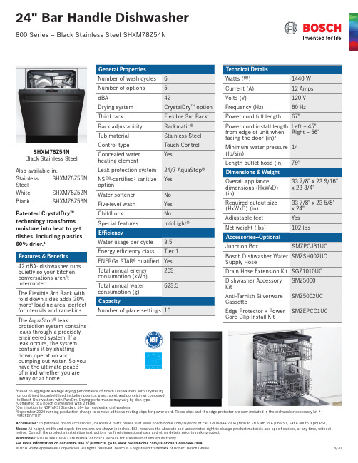
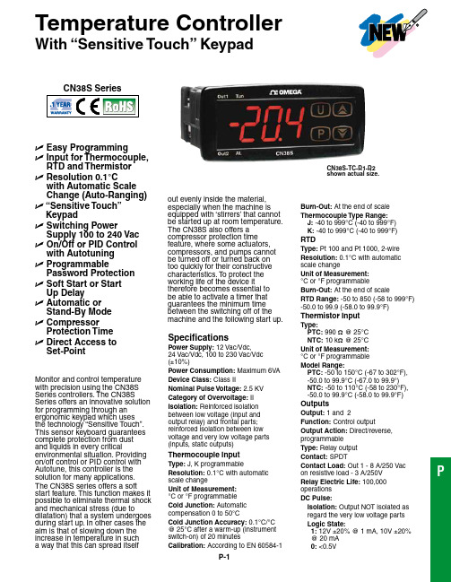
Accessories: To purchase Bosch accessories, cleaners & parts please visit /us/store or call 1-800-944-2904 (Mon to Fri 5 am to 6 pm PST, Sat 6 am to 3 pm PST).SHXM78Z54N Black Stainless Steel Also available in:Stainless Steel SHXM78Z55N White SHXM78Z52N BlackSHXM78Z56NPatented CrystalDry™ technology transforms moisture into heat to get dishes, including plastics, 60% drier.142 dBA: dishwasher runs quietly so your kitchen conversations aren’t interrupted.The Flexible 3rd Rack with fold down sides adds 30% more 2 loading area, perfect for utensils and ramekins.The AquaStop® leakprotection system contains leaks through a precisely engineered system. If a leak occurs, the system contains it by shutting down operation andpumping out water. So you have the ultimate peace of mind whether you are away or at home.1Based on aggregate average drying performance of Bosch Dishwashers with CrystalDry on combined household load including plastics, glass, steel, and porcelain as compared to Bosch Dishwashers with PureDry. Drying performance may vary by dish type.2Compared to a Bosch dishwasher with 2 racks.3Certification to NSF/ANSI Standard 184 for residential dishwashers. 4September 2020 running production change to remove adhesive routing clips for power cord. These clips and the edge protector are now included in the dishwasher accessory kit # SMZEPCC1UC.Accessories: To purchase Bosch accessories, cleaners & parts please visit /us/store or call 1-800-944-2904 (Mon to Fri 5 am to 6 pm PST, Sat 6 am to 3 pm PST).Installation DetailsJunction box accessoryInstallation DetailsAccessories: To purchase Bosch accessories, cleaners & parts please visit /us/store or call 1-800-944-2904 (Mon to Fri 5 am to 6 pm PST, Sat 6 am to 3 pm PST).。
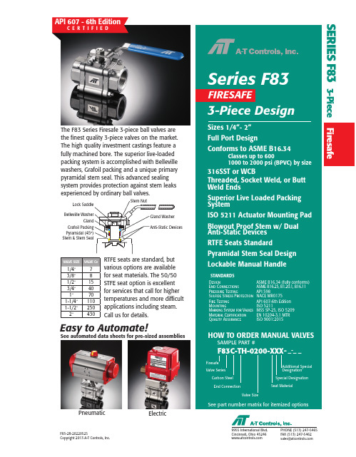
SERIES F83 3-Piece FiresafeThe F83 Series Firesafe 3-piece ball valves are the finest quality 3-piece valves on the market. The high quality investment castings feature a fully machined bore. The superior live-loaded packing system is accomplished with Belleville washers, Grafoil packing and a unique primary pyramidal stem seal. This advanced sealing system provides protection against stem leaks experienced by ordinary ball valves.Easy to Automate!See automated data sheets for pre-sized assembliesPneumaticElectricRTFE seats are standard, but various options are available for seat materials. The 50/50 STFE seat option is excellent for services that call for higher temperatures and more difficult applications including steam. Call us for details.C E R T I F I E DHigh Performance, Full Port 3-Piece Ball ValveISO 5211 Mounting Pad Class 400 to 600960 to 1480 psi (by size)1/4” to 2”* 1/4” THRU 2” QTY = 4 PCS* 2-1/2” QTY = 6 PCSHigh Performance, Full Port 3-Piece Ball ValveISO 5211 Mounting Pad Classes up to 600 1500 - 2000 psi (by size)SIZED FOR60 psi AIR SUPPL YSIZE MODEL1/4"F83-TX-025/TR1D-XX 3/8"F83-TX-038/TR1D-XX 1/2"F83-TX-050/TR1D-XX 3/4"F83-TX-075/2R2D-XX 1"F83-TX-100/2R2D-XX 1-1/4"F83-TX-125/2R2D-XX 1-1/2"F83-TX-150/2R3D-XX 2"F83-TX-200/2R4D-XXStem & Stem SealAPI 607 - 6th EditionC E R T I F I E DFiresafe tested to API-607(valve only)SERIES F8 3 3-Piece FiresafeDIMENSIONS (IN)VALVE SIZE A B C D E1/4" 5.98 2.760.79 2.65 2.583/8" 5.98 2.760.79 2.65 2.581/2" 5.98 2.760.79 2.65 2.583/4"7.95 3.430.79 2.65 3.291"7.95 3.430.79 2.78 3.291-1/4"7.95 3.430.79 2.90 3.291-1/2"9.29 4.490.79 3.13 4.412"9.29 4.490.79 3.42 4.41 DIMENSIONS SHOWN ARE FOR ASSEMBLIES SIZED FOR 80 PSI SUPPLYDESCRIPTION PART NO.SUFFIXDIMENSIONS (IN)VALVE SIZEABCDE1/4"7.95 3.430.79 2.65 3.293/8"7.95 3.430.79 2.65 3.291/2"7.95 3.430.79 2.65 3.293/4"7.95 3.430.79 2.62 3.291"9.29 4.490.79 2.78 4.411-1/4"9.29 4.490.79 2.90 4.411-1/2"9.294.490.79 3.13 4.412"10.87 4.880.79 3.42 4.82DIMENSIONS SHOWN ARE FOR ASSEMBLIES SIZED FOR 80 PSI SUPPLYDESCRIPTIONPART NO.SUFFIXAPI 607 - 6th EditionC E R T I F I E DFiresafe tested to API-607(valve only)SIZED FOR 60 psi AIR SUPPL YSIZEMODEL1/4"F83-TX-025/2R2S-XX 3/8"F83-TX-038/2R2S-XX 1/2"F83-TX-050/2R2S-XX 3/4"F83-TX-075/2R3S-XX 1"F83-TX-100/2R3S-XX 1-1/4"F83-TX-125/2R3S-XX 1-1/2"F83-TX-150/2R4S-XX 2"F83-TX-200/2R4S-XXSERIES F 83 3-Piece FiresafeBelleville Washer Stem & Stem SealSee valve part number matrixfor complete part number andoptions.NOTE: Heater and thermostat standard(2) auxiliary switches standardAPI 607 - 6th EditionC E R T I F I E D(valve only)F83C-TH-0200-XXX-X-_ _SAMPLE PART #(2) Valve Series(1) Prefix(4) End Connection(6) Seat, Lining & TrimMaterial(5) Valve Size(7) Special Designation(8) AdditionalSpecials(9,10,11) Options(3) Body/Ball/StemMaterialF83C-TH-0200-XXX-X-_ _SAMPLE PART #(2) Valve Series(1) Prefix(4) End Connection(6) Seat, Lining & TrimMaterial(5) Valve Size(7) Special Designation(8) AdditionalSpecials(9,10,11) OptionsMANUAL VALVE(3) Body/Ball/StemMaterialHOW TO ORDER:Manual Valves w/ OptionsHOW TO ORDER:Automated ValvesSAMPLE PART #(2) Valve Series(3) Body/Ball/StemMaterial(6) Valve Size(5) Seat, Lining, & TrimMaterial(4) End Connection (7) TRIAC Actuator Series(7) Actuator Size (7) Double Acting(8) Accessory F83C-TX-100/2R3D-XX-_TFM™ is a trademark of Dyneon™, a 3M Company.(1) Prefix。
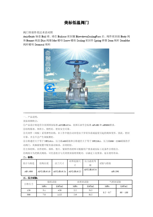
美标低温阀门阀门零部件英汉术语对照AxisGuide轴套Ball球、球芯Ballseat密封圈BlowdownSealingFace启、阀件密封面Body阀体Bonnet阀盖Disc阀瓣Mut螺母Screw螺栓Sealing密封件Spring弹簧Stem阀杆StemMut 阀杆螺母Stemseal填料一、产品说明:美标闸阀特点:①产品设计制造符合美国国家标准ANSIB16.34,美国石油学会标准AP16D和API600要求。
②结构紧凑、体积小、刚性好、密封安全可靠。
③关闭件(闸板)采用弹性结构,在工作中能自动补偿由于异常负荷或温度引起的阀体变形。
因此,密封可靠,并且不会产生闸板楔柱。
④公称通径大于等于NPS1011,压力级400磅级和公称通径大于等于NPSS611、压力级600~2500磅级的手动阀门,其操做装置中配有滚动轴承,启闭轻松。
⑤主体材料、内件材料、填料、垫片、紧固件的材料可根据用户要求或实际工况条件合理组合。
⑥阀座可为更掀式阀座,可任意组合与关闭密封面材质配对,以满足工况要求,延长使用寿命。
二、标准:设计与制造结构长度法兰尺寸对焊连接尺寸压力温度等级试验与检验AP1 600 ANS1B16.10 ANS1B16.5a ANS1B16.25 ANS1B16.34AP1598三、压力试验:公称压力强度试验水密封试验气密封试验MPa Lbf/in2 MPa Lbf/in2 MPa Lbf/in2150 3.1 450 2.2 3150.5~0.7 60~100 300 7.8 1125 5.6 815600 15.3 2225 11.2 1630 900 23.1 3350 16.8 2440 1500 38.4 5575 28.1 4080 2500 64.6936747.46873四、主要零件材料及性能: 壳体 ASTM A216WCB ASTMA351 CF8闸板WCBCF8 CF 8M Monel 阀杆 F6a F304 F316 MonelF304闸板密封面13C r 13C r S T L 304 S T L 316 S TLMonel 304 304 STL阀座密封面13C rS T L S T L 304 S T L 316 S TLMonel304 ST LSTL 壳体 ASTM A351CF3 ADTM A351 CF8M ASTM A351 CF8闸板 阀杆F304LF316F316L闸板密封面 304L304L S T L 316 316 STL316L 316L STL阀座密封面 304L STL S T L 316 S TLSTL 316L S T LSTL五、工洲牌美标闸阀主要外形尺寸:ANS1 Class150NPS 2 21/23 4 6 8112141618224262833236442L RF1781912329267292333563814643245758559616166711762787BW21624128335434194575257261667118138649149149651161671118手动H14495158577595511613751571765198- - - - - - - - -Do222533535445567- - - - - - - - -伞齿轮H2- - - - - - - -16681922115221526298346313632933726464229电动H3- - - - - - - -16681922115221526298346313632933726464229ANS1 Class300NPS 2 21/23 4 6 8112141618224262833236442L RF216241283354641945752762838914991114312451346169715241727- -BW216241283354641945752762838914991114312451346169715241727- -手动H147525535635851251231461645-184- - - - - - - - -Do22333544556-6- - - - - - - - -伞齿轮H2- - - - - - - - - -1935215525722983131353293- - -电动H3- - - - - - - - - -19352155257229831313532933754412453六、工洲牌美标闸阀主要外形尺寸:ANS1 Class600NPS 2 21/2 3 4 6 8 10 12 14 16 18 20 24 26 28 30L RF 292 3303564325596678783888999109211941397144815491651 BW 292 3303564325596678783888999109211941397144815491651手动H1 474 530547703913107712761499- - - - - - - - Do 250 250303545506068- - - - - - - -伞齿轮H2 - - - - - - - 147016252089221126162921296030503112电动H3 - - - - - - - 147016252089221126162921296030503112ANS1 Class900NPS 2 21/23 4 6 81214161820 24L RF3684193814576173796512911312171321 1549BW36841938145761737- - - - - -手动H162756958251651318- - - - - -Do33535456- - - - - -伞齿轮H2- - - -8941691187721432312750 3150电动H3- - - -8941691187721432312750 3150ANS1 Class1500NP S 2 3 4 6 811214161820 24L RF371473549- - - - - - - - -BW- - - - - - - - - - - -手动H16147592711911524185421842216- - - -Do- - - - - - - - - - - -伞齿H2- - -11151821- - - - -轮91 24 54 84 电动 H 3- - -1191 1524 1854 2184 2216 2316 26228403310ANS1 Class2500NPS234681012 LRF451578673914102212701422 BW451578673914102212701422手动 H1 630 890 - - - - - Do - - - - - - - 伞齿轮H2------- 电动H3--1911347144516921914一、产品美标、日标球阀的详细资料: 产品型号:Q41F产品名称:美标、日标球阀二、产品性能规范:公称压力(PN) 1.6 2.5 4.0 6.4壳体试验压力 2.4 3.8 6.0 9.6密封试验(液) 1.8 25.8 4.4 7.0密封试验(气)0.5~0.7适用介质C P R水、油品、蒸汽硝酸类醋酸类适用温度≤200三、主要堆零件材料:名称WCB类CF8类CF3类CF8M类CF3M类阀体左体A216-WCB A315-CFB A35-CF3 A351-CF8M A351-CF3M球体B2-B8 A105-1025 A182-F304L A182-F304L A132-F316 A182-F316L B8以上A216-WCB A351-CF8M A351-CF3 A351-CF8M A351-CF3M 阀杆A182-F6a A182-F304 A182-F304L A182-F336 A182-F316L 阀座PTFE/增强PTFE/NYLIN阀座支承圈A105-1025 A182-F304 A182-F304L A182-F316 A182-F316L 弹簧3yc-7/17-49HO型圈NBR 氟橡胶螺柱A193-B7 A193-B8螺母A194-2H A194-8四、工洲牌美标高平台二片式球阀10K主要连接及重量:尺寸inch 1/2″3/4″1″1-1/2″2″2-1/2″3″4″5″6″8″10″DN 15 20 25 4 50 65 80 100 125 150 200 250 L mm 108 117 127 165 178190 203 229 356 394 457 533 H mm 59 63 75 97 107142 152 178 252 272 342 345W mm 130 130 160 230 230 400 400 700 1101100 1500 1500重量㎏ 2.3 3.0 4.5 7.0 9.5 15.0 19.0 33.0 58.0 93.0 160.0 200. 0五、工洲牌美标高平台二片式球阀20K主要连接尺寸及重量:尺寸inch 1/2 3/4 1 1-1/2 2 2-1/2 3 4 5 6 8 10 DN 15 20 25 4 50 65 80 100 125 150 200 250L mm 140 152 165 190 216 241 283 305 381 403 502 568 H mm 59 63 75 97 107 142 152 178 252 272 342 345 W mm 130 130 160 230 230 400 400 700 1100 1100 1500 1500重量㎏2.5 3.5 5.5 10.5 14.5 23.5 30.0 55.0 81.0 118.0 200.250.六、工洲牌美标高平台二片式球阀150Lb外形尺寸和连尺寸:公称通径单位L D T G C n-Φd W H in mm1/2″15 ㎜108 89 12 35 60.5 4-15 115 72 in 4.25 3.5 0.47 1.38 2.38 4-0.59 4.53 28.33/4″20 ㎜117 98 12 43 70 4-15 115 76 in 4.61 3.86 0.47 2 3.13 4-0.59 5.9 3.621″25 ㎜127 108 12 51 79.5 4-15 150 92 in 5 4.25 0.47 2 3.13 4-0.59 5.9 3.621-1/2″40 ㎜165 127 14.3 73 89.5 4-16 200 123 in 6.5 5 0.56 2.88 3.88 4-0.62 7.87 4.842″50 ㎜178 152 15.9 92 120.5 4-19 200 132 in 7 6.00 0.625 3.62 4.75 4-0.75 7.87 5.202-1/2″65 ㎜190 178 17.5 105 139.5 4-19 320 164 in 7.5 7 0.69 1.12 5.50 4-0.75 12.6 6.453″80 ㎜203 190 19.1 127 152.4 4-19 320 173 in 8 7.50 0.75 5 6 4-0.75 12.6 8.64″100 ㎜229 229 23.9 157 190.5 4-19 450 210 in 9 9 0.94 6.19 7.5 4-0.75 17.72 8.266″150 ㎜394 279 26 216 241.5 8-22 8000 288 in 15.5 10.98 1.02 8.5 9.50 8-0.88 31.5 1.348″200 ㎜457 343 29 270 298.5 8-22 1120 374 in 18.00 13.50 1.12 10.62 11.75 8-0.88 44.10 14.7210″250 ㎜533 406 31 324 362 12-25 1420 366 in 20.98 16 1.2 12.75 14.75 12-1 55.12 14.4012″300 ㎜610 483 32 381 432 12-25 1420 412 in 24 19 1.26 15 17 12-1 55.12 16.22七、工洲牌美标高平台二片式球阀300Lb外形尺寸和连接尺寸:公称通径单位L D T G C n-Φd W H in mm1/2″15 ㎜140 95 15 35 66.5 4-15 115 72 in 5.51 3.74 0.59 1.38 2.62 4-0.59 4.53 28.33/4″20 ㎜152 117 16 43 82.5 4-19 115 76 in 5.98 4.61 0.62 1.69 3.25 4-0.75 4.53 29.91″25 ㎜165 124 18 51 89 4-19 150 92 in 6.5 4.9 0.71 2 3.5 4-0.75 5.9 3.621-1/2″40 ㎜190 156 20.7 73 114.5 4-22 200 123 in 7.5 6.12 0.81 2.88 4.51 4-0.88 7.87 4.842″50 ㎜216 165 22.3 92 127 8-19 200 132 in 8.5 6.5 0.88 3.62 5 8-0.75 7.87 5.202-1/2″65 ㎜241 190 25.4 105 149 8-22 320 164 in 9.5 7.5 1 4.12 5.87 8-0.88 12.6 6.453″80 ㎜283 210 28.5 127 168.5 8-22 320 173 in 11.25 8.25 1012 5 6.62 8-0.88 12.6 6.84″100 ㎜305 254 31.8 157 200 8-22 450 210 in 12 10 1.25 6.19 7.88 8-0.88 17.72 8.266″150 ㎜403 318 36.6 216 270 12-22 1120 336 in 15.875 12.5 1.44 8.5 10.62 12-0.88 44.10 13.238″200 ㎜502 381 42 270 330 12-25 1420 385 in 19.76 15 16.5 10.62 12.99 12-1 55.12 15.1610″250 ㎜568 444 48 324 387.5 16-29 1420 370 in 22.36 17.50 1.89 12.75 15.25 16-1.12 55.12 14.56一、上海工洲阀门有限公司美标固定三段式球阀产品详细介绍:1.美标固定三段式球阀所有部件均为锻件2.采用下装式阀杆,设备倒密封结构3.采用镶嵌式阀座,阀座背后设备O型圈,确保介质不外漏4.密封面采用尼龙1010,它的磨擦系数通常为巴氏合金的1/3,因此它是一种自然滑性材料。

1.4阀门及小型设备代号解释1.4.1闸阀(GATE VALVE)、截止阀(GLOBE VALVE)止回阀(CHECK VALVE)、针型阀(NEEDLE GLOBE VALVE) - / 特殊代码(3位)见表1.4.1-8阀芯材质,见表1.4.1-7阀体材质,见表1.4.1-6连接型式,见表1.4.1-5接管壁厚,见表1.2.1-2*传动机构,见表1.4.1-4结构型式,见表1.4.1-3压力等级,见表1.4.1-2阀门类别,见表1.4.1-1 注*:只有“连接型式”中为BW时才有此项✷对CL900.1500.2500三个等级的阀门,一般采用压力密封阀盖,此时“阀盖垫片”和“阀盖螺栓”项缺省。
✹等级1a、2a、3a、4a、5a适用于JB标准阀门。
注:✶如果阀门的结构型式为“2”、“8”和“9”,即阀盖为压力密封阀盖,则该表中的“阀盖垫片材料”和“阀盖螺栓材料”栏缺省。
✷如果阀门的结构型式为“5”,则该表中的“阀杆填料”栏缺省。
表1.4.1-8,特殊代码1.4.2球阀(BALL VALVE)特殊代码(3位)见表1.4.1-8阀芯材质,见表1.4.2-2阀体材质,见表1.4.1-6连接型式,见表1.4.1-5接管壁厚,见表1.2.1-2*传动机构,见表1.4.1-4结构型式,见表1.4.2-1压力等级,见表1.4.1-2阀门类别:球阀/BALL VALVE,代号-Q1.4.3 旋塞阀(PLUG VALVE)阀芯材质,见表1.4.3-2阀体材质,见表1.4.1-6连接型式,见表1.4.1-5接管壁厚,见表1.2.1-2*传动机构,见表1.4.1-4结构型式,见表1.4.3-1压力等级,见表1.4.1-2阀门类别:旋塞阀/PLUG VALVE,代号-P1.4.4 蝶阀(BUTTERFLY VALVE)阀芯材质,见表1.4.4-2阀体材质,见表1.4.1-6连接型式,见表1.4.1-5接管壁厚,见表1.2.1-2*传动机构,见表1.4.1-4结构型式,见表1.4.4-1压力等级,见表1.4.1-2阀门类别:蝶阀/BUTTERFLY VALVE,代号-D1.4.5 疏水阀(STEAM TRAP VALVE)阀芯材质,见表1.4.5-2阀体材质,见表1.4.1-6连接型式,见表1.4.1-5结构型式,见表1.4.5-1压力等级,见表1.4.1-2阀门类别:疏水阀/STEAM TRAP VALVE,代号-S1.4.6 过滤器(STRAINER)阀体材质,见表1.2.1-3连接型式,见表1.4.1-5接管壁厚,见表1.2.1-2*结构型式,见表1.4.6-1压力等级,见表1.3.1-2阀门类别:过滤器(STRAINER),代号-T1.4.7视镜(SIGHT GLASS)阀体材质,见表1.2.1-3连接型式,见表1.4.1-5接管壁厚,见表1.2.1-2*结构型式,见表1.4.7-1压力等级,见表1.3.1-2阀门类别:视镜(SIGHT GLASS),代号-G1.4.8仪表测压阀(Y)接管材质,见表1.4.8-3阀芯材质,见表1.4.1阀体材质,见表1.2.1-3近主管接管长度,见表1.4.8-2接管壁厚,见表1.2.1-2压力等级,见表1.3.1-2主阀类型,见表1.4.8-1阀门类别:仪表测压阀,代号-Y。
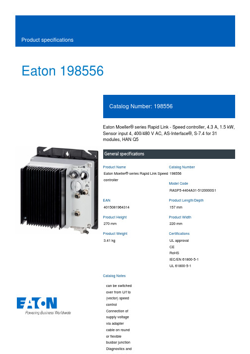
Eaton 198556Eaton Moeller® series Rapid Link - Speed controller, 4.3 A, 1.5 kW, Sensor input 4, 400/480 V AC, AS-Interface®, S-7.4 for 31 modules, HAN Q5General specificationsEaton Moeller® series Rapid Link Speed controller198556RASP5-4404A31-5120000S14015081964314157 mm 270 mm 220 mm 3.41 kgUL approval CE RoHSIEC/EN 61800-5-1 UL 61800-5-1Product NameCatalog NumberModel CodeEANProduct Length/Depth Product Height Product Width Product Weight Certifications Catalog Notes can be switched over from U/f to (vector) speed control Connection of supply voltage via adapter cable on round or flexible busbar junction Diagnostics and480 VIs the panel builder's responsibility. The specifications for the switchgear must be observed.480 V AC, 3-phase400 V AC, 3-phaseMeets the product standard's requirements.1.5 kW500 VMeets the product standard's requirements.-40 °C380 VInternal DC linkPC connectionKey switch position AUTOSelector switch (Positions: REV - OFF - FWD)Two sensor inputs through M12 sockets (max. 150 mA) for quick stop and interlocked manual operationThermo-click with safe isolationKey switch position OFF/RESETKey switch position HANDPTC thermistor monitoringFour fixed speedsIGBT inverterControl unit0 Hz200 %, IH, max. starting current (High Overload), For 2 seconds every 20 seconds, Power section Electromagnetic compatibility (EMC)Configuration to Rockwell PLC for Rapid LinkGeneration Change RA-SP to RASP5Generation change from RA-SP to RASP 4.0Connecting drives to generator suppliesGeneration change RAMO4 to RAMO5Generation change from RA-MO to RAMO 4.0Generation Change RASP4 to RASP5Rapid Link 5 - brochureDA-SW-drivesConnect - InstallationshilfeDA-SW-drivesConnect - installation helpDA-SW-USB Driver PC Cable DX-CBL-PC-1M5DA-SW-Driver DX-CBL-PC-3M0DA-SW-drivesConnect USB Driver DX-COM-PCKITDA-SW-USB Driver DX-COM-STICK3-KITDA-SW-drivesConnectMaterial handling applications - airports, warehouses and intra-logisticsProduct Range Catalog Drives EngineeringProduct Range Catalog Drives Engineering-ENDA-DC-00004184.pdfDA-DC-00004514.pdfDA-DC-00003964.pdfDA-DC-00004508.pdfeaton-bus-adapter-rapidlink-speed-controller-dimensions-003.eps eaton-bus-adapter-rapidlink-speed-controller-dimensions-002.eps eaton-bus-adapter-rapidlink-speed-controller-dimensions-004.eps eaton-bus-adapter-rapidlink-speed-controller-dimensions.epsETN.RASP5-4404A31-5120000S1.edzIL034085ZUMains voltage - max10.11 Short-circuit ratingRated operational voltage10.4 Clearances and creepage distancesOutput at quadratic load at rated output voltage - max Output voltage - max10.2.3.1 Verification of thermal stability of enclosures Ambient storage temperature - minMains voltage - minFitted with:Output frequency - minStarting current - max Application notes BrochuresCatalogs Certification reports DrawingseCAD model Installation instructions10 kA40 °CAS-Interface2 HP500 Hz8 kHz, 4 - 32 kHz adjustable, fPWM, Power section, Main circuitParameterization: drivesConnectDiagnostics and reset on device and via AS-Interface Parameterization: FieldbusParameterization: KeypadParameterization: drivesConnect mobile (App)-10 °C≤ 0.6 A (max. 6 A for 120 ms), Actuator for external motor brakeDoes not apply, since the entire switchgear needs to be evaluated.4.3 ADoes not apply, since the entire switchgear needs to be evaluated.Does not apply, since the entire switchgear needs to be evaluated.Speed controller Rapid Link 5MN034004EN MZ040046_EN MN040003_ENramo5_v19.dwg rasp5_v19.stpRated conditional short-circuit current (Iq)Ambient operating temperature - maxCommunication interfaceAssigned motor power at 115/120 V, 60 Hz, 1-phase Output frequency - maxSwitching frequencyFeaturesAmbient operating temperature - minBraking currentNumber of HW-interfaces (serial TTY)10.6 Incorporation of switching devices and components Nominal output current I2N10.2.6 Mechanical impact10.3 Degree of protection of assembliesProduct categoryRadio interference class Installation videos Manuals and user guidesmCAD modelC1: for conducted emissions onlyC2, C3: depending on the motor cable length, the connected load, and ambient conditions. External radio interference suppression filters (optional) may be necessary.Heat dissipation capacity Pdiss0 WRated control voltage (Uc)24 V DC (-15 %/+20 %, external via AS-Interface® plug) 400/480 V AC (external brake 50/60 Hz)Assigned motor power at 460/480 V, 60 Hz, 3-phase2 HPNumber of HW-interfaces (RS-422)Mains current distortion120 %ProtocolAS-Interface profile cable: S-7.4 for 31 modulesASI10.9.2 Power-frequency electric strengthIs the panel builder's responsibility.Overvoltage categoryIIIDegree of protectionIP65NEMA 12Ambient storage temperature - max70 °CRated impulse withstand voltage (Uimp)2000 VConnectionPlug type: HAN Q5Overload currentFor 60 s every 600 sAt 40 °CFunctionsFor actuation of motors with mechanical brakeOutput at linear load at rated output voltage - max1.5 kWMains voltage tolerance380 - 480 V (-10 %/+10 %, at 50/60 Hz)Leakage current at ground IPE - max3.5 mAConverter typeU converter10.2.2 Corrosion resistanceMeets the product standard's requirements.Supply frequency50/60 Hz10.2.4 Resistance to ultra-violet (UV) radiationMeets the product standard's requirements.10.2.7 InscriptionsMeets the product standard's requirements.Shock resistance15 g, Mechanical, According to IEC/EN 60068-2-27, 11 ms, Half-sinusoidal shock 11 ms, 1000 shocks per shaftApplication in domestic and commercial area permittedYesNumber of inputs (analog)Number of phases (output)310.12 Electromagnetic compatibilityIs the panel builder's responsibility. The specifications for the switchgear must be observed.10.2.5 LiftingDoes not apply, since the entire switchgear needs to be evaluated.Number of HW-interfaces (RS-485)1Number of HW-interfaces (industrial ethernet)Efficiency98 % (η)System configuration typeCenter-point earthed star network (TN-S network)AC voltagePhase-earthed AC supply systems are not permitted.10.8 Connections for external conductorsIs the panel builder's responsibility.ProtectionFinger and back-of-hand proof, Protection against direct contact (BGV A3, VBG4)Braking voltage400/480 V AC -15 % / +10 %, Actuator for external motor brakeApplication in industrial area permittedYesClimatic proofing< 95 %, no condensationIn accordance with IEC/EN 5017810.9.3 Impulse withstand voltageIs the panel builder's responsibility.Overload current IL at 150% overload6.5 AInput current ILN at 150% overload4.1 ANumber of HW-interfaces (RS-232)Number of inputs (digital)4Current limitationAdjustable, motor, main circuit0.4 - 4.3 A, motor, main circuitCable lengthC2 ≤ 5 m, maximum motor cable lengthC1 ≤ 1 m, maximum motor cable lengthC3 ≤ 25 m, maximum motor cable length10.5 Protection against electric shockDoes not apply, since the entire switchgear needs to be evaluated.Mounting positionVerticalMains switch-on frequencyMaximum of one time every 60 seconds10.13 Mechanical functionThe device meets the requirements, provided the information in the instruction leaflet (IL) is observed.10.9.4 Testing of enclosures made of insulating materialIs the panel builder's responsibility.Heat dissipation per pole, current-dependent Pvid0 WElectromagnetic compatibility1st and 2nd environments (according to EN 61800-3)Resolution0.1 Hz (Frequency resolution, setpoint value)Assigned motor power at 460/480 V, 60 Hz2 HPRelative symmetric net voltage tolerance10 %Rated operational current (Ie)4.3 A at 150% overload (at an operating frequency of 8 kHz and an ambient air temperature of +40 °C)Number of outputs (analog)Rated operational power at 380/400 V, 50 Hz, 3-phase1.5 kWNumber of HW-interfaces (USB)Operating modeU/f controlBLDC motorsSensorless vector control (SLV)Synchronous reluctance motorsPM and LSPM motorsRated frequency - min45 HzDelay time< 10 ms, Off-delay< 10 ms, On-delayNumber of outputs (digital)Power consumption46 W10.2.3.2 Verification of resistance of insulating materials to normal heatMeets the product standard's requirements.10.2.3.3 Resist. of insul. mat. to abnormal heat/fire by internal elect. effectsMeets the product standard's requirements.Number of HW-interfaces (other)1Rated frequency - max66 HzVibrationResistance: According to IEC/EN 60068-2-6Resistance: 57 Hz, Amplitude transition frequency on accelerationResistance: 10 - 150 Hz, Oscillation frequencyResistance: 6 Hz, Amplitude 0.15 mmShort-circuit protection (external output circuits)Type 1 coordination via the power bus' feeder unit, Main circuit10.7 Internal electrical circuits and connectionsIs the panel builder's responsibility.Braking torque≤ 30 % (I/Ie)Adjustable to 100 % (I/Ie), DC - Main circuitRelative symmetric net frequency tolerance10 %10.10 Temperature riseThe panel builder is responsible for the temperature rise calculation. Eaton will provide heat dissipation data for the devices.Number of HW-interfaces (parallel)Assigned motor power at 230/240 V, 60 Hz, 1-phase2 HPInterfacesMax. total power consumption from AS-Interface® power supply unit (30 V): 190 mANumber of slave addresses: 31 (AS-Interface®) Specification: S-7.4 (AS-Interface®)Number of phases (input)3Eaton Corporation plc Eaton House30 Pembroke Road Dublin 4, Ireland © 2023 Eaton. All Rights Reserved. Eaton is a registered trademark.All other trademarks areproperty of their respectiveowners./socialmedia32.3 W at 25% current and 0% speed 33.2 W at 25% current and 50% speed 35.2 W at 50% current and 90% speed 36.2 W at 50% current and 0% speed 37.6 W at 50% current and 50% speed 46.3 W at 100% current and 90% speed 48.7 W at 100% current and 0% speed 48.7 W at 100% current and 50% speed 0Max. 2000 mAbove 1000 m with 1 % performance reduction per 100 mHeat dissipation at current/speed Number of interfaces (PROFINET)Altitude。


Elevated performance, at easeSilverStone Strider ST50F-230ATX12V Switching Power SupplyWith Active PFCPS/2 500W230Vac only1. Input Requirements1.1 Input VoltageThe power supply shall be operated at universal input voltage defined in the following table.1.2 FrequencyThe input frequency range is from 50Hz to 60Hz.1.3 Inrush CurrentThe max inrush current is 8A for 230VAC01STRIDER SST-ST50F-2301.3.1 Cold Start1.3.2 Warm Start1.4 AC Input Current1.5 EfficiencyThe maximum efficiency >80% in the typical load and 230 Vac input voltage conditions.2. Output Requirements2.1 Output RegulationsNote:(1)The above voltage range should also include ripple and noise.(2)The output voltage should be measured at the terminals of output connector.022.2 DC Load RequirementsNotes:(1)The maximum continuous total DC output power shall not exceed 500 Watts.(2) The maximum continuous combined load on +5V and +3.3V outputs shall not exceed 150 bined load on +12V1 and +12V2 outputs shall not exceed 384 Watts.The maximum continuous combined load on +5V, +3.3V and +12V1,+12V2 outputs shall not exceed 488 Watts.(3)2.3 Cross RegulationThe DC loads shall remain within the ranges specified in 2-2 DC Load Requirements and the DC output voltages also shall remain within the regulation ranges specified in 2-1 Output Regulation when measured at the load end of the output connectors.2.4 +5V standby voltageThe +5Vsb is on whenever the AC power is present.204060801001201401601802550100150200250300500W Cross Regulation (+5V rail +3.3V vs. 12V)12V power (watts)5V +3.3V p o w e r (w a t t s )350385032.5 DC Output Voltage Ripple and NoiseNote :(1)The measurements should be made by crossing a 10uF/ electrolytic and a 0.1uF ceramic disk capacitors at each output with measuring bandwidth from DC to 20 MHz. If ambient temperature is under 20C or over 30C, the AC input should be normal input.2.6 Total Output Power2.7 Remote ON/OFF controlThe power supply outputs shall be enabled with an active-low TTL signal.When TTL signal is low , the DC outputs are to be enabled.When TTL signal is high or open circuited, the DC outputs are to be disabled.Electronic means or a mechanical switch may activate the TTL signal.After the TTL signal is active high, must wait for 3 seconds before active low again.2.8 Power Sequence+12V+5V +3.3VO/P’s ᑻᑻSTRIDER SST-ST50F-230042.9 Power On Time (T1)2.10 Rise Time (T2)2.11 Power Good Delay Time (T3)The test environment is 25 C condition @ normal input.2.12 Power Good Rise Time (T4)2.13 Hold Up T ime (T5)The test environment is 25ᑻC & full load condition @ nominal input.2.14 Power Fail Signal (T6)Power good signal shall go to a down level 1ms before +5V output voltage falls below the regulation limits during PS-ON signal pull high.3. Protections3.1 Over Voltage ProtectionWhen the DC outputs (+5V, +12V, +3.3V) have over voltage condition, the power supply shall provide latch mode over voltage protection.ᑻ053.2 Short Circuit ProtectionA short circuit placed to ground shall cause no damage or power supply shall be shutdown.(The contact resistance is 0.05 ohm when the outputs short circuit.)3.3 Protection ResetWhen the power supply latches into shutdown condition due to a fault on an+5V,+3.3V,+12V1,+12V2 output( OVP , UVP ,OCP ), the protection shall reset after the fault has been removed, use remote on/off control or recycle the AC power again for a typical of 5 seconds.3.4 Over 3.6 Over Current Powershoot ProtectionAny output overshoot at turn on shall be less than 15% of the normal output value (with resistive load) as described in sec. 2.1.At 230Vac input the power supply will shut down all DC output within 110% to 150% of full load.3.5 Over power Protection4. ENVIRONMENT4.1 Operation/Storage Temperature RangeOperation : 5Cto 50C (normal input)Storage : -40C to 70C 4.2 Humidity (none condensing)Operation : 20% to 85% RH (normal input)Storage : 10% to 95% RHLoad 100%80%50ᑻC25ᑻC ᑻᑻᑻᑻ STRIDER SST-ST50F-230066. EMI Requirements7. Dielectric Voltage Withstand (HI-POT)The power supply shall withstand for 3 seconds without breakdown the application of an1800Vac-supply voltage applied between both input line and chassis (15mA AC Cutoff current). Isolating transformers shall similarly withstand 4242Vdc applied between both primary and secondary windings for a minimum of one minute.8. PFCActive Power Factor Correction, complies with EN 61000-3-2: 2000, Class D.9. Electrostatic Discharge (ESD)Comply with IEC 61000-4-2.10. EFT/ BurstComply with IEC 61000-4-4Comply with IEC 61000-4-5.The power supply shall have a minimum mean time between failure greater than 100,000 hours atcontinuous operation of 100% load and an ambient temperature of 25 C111. Surge Applying 230 Vac + 10% input voltage and maximum load (80%) for this product in 45 + 5 C chamber.12. Burn-In13. M.T.B.F.A6-1.CE5. Safety5-1. TUV EN 60950-15-2. CB07OO14.1 Physical Dimension150 mm (W) × 86 mm (H) × 160 mm (D)14.2 Connectors Define14. MECHANICAL REQUIREMENTSSTRIDER SST-ST50F-230EPS 12V 8PIN connectorATX 12V 4PIN(4+4PIN EPS 12V in split mode)08SATA connector6PIN PCI Express Connector09STRIDER SST-ST50F-230NO.G1*******。
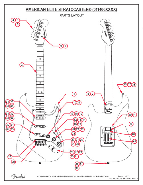
PARTS LISTREF#DESCRIPTION PARTNUMBER 1BODY AM ELITE STRAT 3TSB7708470500 1BODY AM ELITE STRAT BLK7708471510 1BODY AM ELITE STRAT OLP7708471523 1BODY AM ELITE STRAT ACB7708472531 1BODY AM ELITE STRAT SBM7708471536 1BODY AM ELITE STRAT TBS7708472552 1BODY AM ELITE STRAT ABM7708471596 2NECK ASSY AM ELITE STRAT MAPLE7708464000 2NECK ASSY AM ELITE STRAT ROSEWOOD7708465000 3KEY LOCKING 1,2,3 POLISHED CHROME EA0073114000 4BUSHING KEY SET0058820049 5WASHER KEY SET 0053106049 6STRING TREE AM ELITE GUITAR CHROME7708381000 7SCREW SMA 2 X 9/16 FHP NICKEL0051621000 8NECK PLATE GUITAR DELUXE CHROME ALUM RH NO HOLE7708496000 9SCREW SMA 8 X 1-3/4 OHP NICKEL0015636049 10PICKGUARD AM ELITE STRAT SSS MG/BLK/MG 7708282000 10PICKGUARD AM ELITE STRAT SSS BROWN SHELL7708281000 11SCREW SMAB 4 X 1/2 ONP NICKEL0015578049 125-WAY SWITCH LEVER DISCRETE/COM0078776000 13SWITCH KNOB VINTAGE AGED WHITE0994938000 14SCREW M 6-32 X 5/8 RHP NICKEL0015800049 15CAPACITOR CD .01µF 600V 10% 1/2” DIAMETER0054504049 16RESISTOR 1/4W 470KΩ0066911000 17KNOB STRAT VOLUME S-1 SOFT OVERMOLD AGED WHITE7708070000 18SWITCH CAP S-1 STRAT AGED WHITE VOLUME0059266030 19SWITCH/POT S-1 250K .25 BUSHING W/NUT & WASHER0078777000 20WASHER LOCKING INTL 3/8 X .687 X .065 NICKEL0016436049 21NUT HEX 3/8-32 X 3/32 NICKEL0016352049 22CONTROL 250K 10% TAPER 0078779000 23KNOB STRAT TONE SOFT OVERMOLD AGED WHITE7708072000 24CONTROL 250K 10% TAPER NO-LOAD 0078780000 25CAPACITOR MPF RDL .022µF 250V 10%0024832000 26FERRULE JACK CHROME0991940000 27JACK PHONE OPEN CIRCUIT 110021956049*=NOT PICTURED IN DIAGRAMREF#DESCRIPTION PARTNUMBER 28BRIDGE ASSY STRAT AM DLX RH0077092000 28A BRIDGE PLATE ULTRA STRAT0036527000 28B BLOCK TREMOLO AM DLX STRAT RH 0077090000 28C BRIDGE SECTION ULTRA STRAT0990840100 28D SPRING BRIDGE 4 COIL 3/8 BLACK0019394049 28E SPRING-BRIDGE 3 COIL 1/4 BLACK0019395049 28F SCREW M 4-40x5/8 PHP BLK0017031049 28G SCREW HEIGHT ADJ. 1/40026779049 28H SCREW HEIGHT ADJ. 5/160026780049 28I SCREW M 8-32x3/8 FHP NI0019656049 28J SPRING CLIP, ULTRA0036531000 28K BUSHING NYL BLK .31OD .22ID x .87L0036614000 28L SCRW SET 10-32x3/16 HEX SKT FP BLXL0036615049 29PIVOT POST ASSY0093273000 30PICKUP ASSY STRAT DELUXE NOISELESS AGED WHITE BRIDGE7708558000 31COVER PICKUP STRAT DELUXE NOISELESS AGED WHITE7708561030 32SCREW SPECIAL M 4-40 X 13/16 #5 HEAD NICKEL0099474000 33TUBING SILICONE RUBBER CUT RED .5000063398000 34PICKUP ASSY STRAT DELUXE NOISELESS AGED WHITE MIDDLE7708557000 35PICKUP ASSY STRAT DELUXE NOISELESS AGED WHITE NECK7708428000 36STRAP BUTTON CHROME SET W/HDWR0990690000 37SCREW SMAB 5 X 1 OHP NICKEL0015610049 38FELT WASHERS BLACK V0994929000 38FELT WASHERS WHITE0994930000 39BACK COVER STRAT STD W/SLOT BROWN SHELL0991324000 39BACK COVER STRAT STD W/SLOT MG/BLK/MG0054029000 40SPRING CLAW TENSION NICKEL0010272100 41SPRING TREMOLO TENSION BLK 0018671049 *CASE MOLDED AM ELITE GUITAR7708547000 *TREMOLO ARM ULTRA DLX SNAPIN 0036534049 *WRENCH .050 HEX KEY SHORT ARM 0018531049 *WRENCH 3/32 HEX KEY SHORT ARM0018622000*=NOT PICTURED IN DIAGRAMPICKUP WIRING .01µF.022µFBLACK & WHITEWIRES FROM OUTPUTVOLUMES1 SWITCHBLACK WIRETO TREM CLAW NECK PICKUPMIDDLE PICKUPBRIDGE PICKUP5-WAY SWITCHRESISTOR 470KΩTONE 1 CONTROL TONE 2 CONTROLCAPACITOR.01µF CAPACITOR.022µFSWITCH AND CONTROL FUNCTION1910VOLUME8234765TONE124356TONE132154801978769212. BRIDGE PICKUP IN PARALLEL WITH NECK & MIDDLE PICKUPS IN SERIES.1. NECK PICKUP IN PARALLEL WITH MIDDLE & BRIDGE PICKUPS IN SERIES.MASTER VOL.S-1 SWTICHTONE 1TONE 25-WAY SWTICHNECK PICKUP (A)MID PICKUP (B)BRIDGE PICKUP (C)2345PICKUP IS OFFPICKUP IS ON 1DIMINISHED VOLUMETONE CONTROLS-1 SWITCH ON (DOWN POSITION)51432T1 ONLYT2 ONLYT1 & T2T2 ONLYT2 ONLY(UP POSITION)S-1 SWITCH OFF SELECTOR POSITION5 WAY TONE CONTROL51432T1 ONLY T2 ONLY T2 ONLYMIDDLE PU (B)BRIDGE PU (C)NECK PU (A)SELECTOR POSITION5 WAY 101897L U V OE M 101897L U V OE M COMBINED PICKUPS ARE IN PARALLELCOMBINED PICKUPS ARE IN SERIES T1 & T2T2 ONLY AS SHOWN ADDITIONAL COMMENTPARALLELSERIESMIDDLE PU (B)BRIDGE PU (C)NECK PU (A)SERIESPARALLEL。

上海笃特马弗炉说明书
陶瓷纤维炉膛(型号后带“A”系列):能满足各种快速烧结的要求,是传统炉膛的升级产品。
耐火砖炉膛(型号后带“N”系列):是传统的耐火材料,具有应用广泛,性价比高等特点。
大屏幕液晶显示,整机一体式设计,合理的门炉设计,使开门操作更加安全便捷。
箱体采用优质冷轧钢板,外壳柒色由高温烘烤而成,更加耐用。
采用微电脑PID温度控制器,控温精准可靠。
重量轻,与传统的马弗炉相比重量轻1/2左右,移动更加方便。
升温速度快,比普通马弗炉的升温速率提高约1倍。
使用更加高效。
外观设计更加合理,温度均匀,环保节能,使用更加便捷。
设有过流,过压、过热、漏电、短路等多种安全保护措施,确保使用更加安全。
隔热效果佳,箱体壁和炉膛采用双层结构设计,并用陶瓷纤维板做隔热保温材料,升温至1000℃时,炉体表面温度仅约50℃,并可保持1小时后外壳表面仍不烫手,避免烫伤。
技术参数:。
STE38NB50FN -CHANNEL 500V -0.11Ω -38A -ISOTOPPowerMESH ™MOSFETs TYPICAL R DS(on)=0.11Ωs EXTREMELY HIGH dv/dt CAPABILITYs ±30V GATE TO SOURCE VOLTAGE RATING s 100%AVALANCHE TESTED s LOW INTRINSIC CAPACITANCE s GATE CHARGE MINIMIZED sREDUCED VOLTAGE SPREADDESCRIPTIONUsing the latest high voltage MESH OVERLAY ™process,STMicroelectronics has designed an ad-vanced family of power MOSFETs with outstand-ing performances.The new patent pending strip layout coupled with the Company’s proprietary edge termination structure,gives the lowest RDS(on)per area,exceptional avalanche and dv/dt capabilities and unrivalled gate charge and switching characteristics.APPLICATIONSs HIGH CURRENT,HIGH SPEED SWITCHING s SWITCH MODE POWER SUPPLY (SMPS)s DC-AC CONVERTER FOR WELDING EQUIPMENT AND UNINTERRUPTABLE POWER SUPPLY AND MOTOR DRIVE ®INTERNAL SCHEMATIC DIAGRAMDecember 1999ABSOLUTE MAXIMUM RATINGSSymbol ParameterValue Unit V DS Drain-source Voltage (V GS =0)500V V DGR Drain-gate Voltage (R GS =20k Ω)500V V GS Gate-source Voltage±30V I D Drain Current (continuous)at T c =25o C 38A I D Drain Current (continuous)at T c =100oC 24A I DM (•)Drain Current (pulsed)152A P tot Total Dissipation at T c =25o C 400W Derating Factor3.2W/o C dv/dt (1)Peak Diode Recovery voltage slope4.5V/nsT s tg Storage Temperature-65to 150o C T jMax.Operating Junction Temperature150oC (•)Pulse width limited by safe operating area(1)I SD ≤38A,di/dt ≤200A/µs,V DD ≤V (BR)DSS ,T j ≤T JMAXTYPE V DSS R DS(on)I D STE38NB50F500V<0.14Ω38AISOTOP1/8THERMAL DATAR thj-case R thj-amb R thc-sinkT l Thermal Resistance Junction-case MaxThermal Resistance Junction-ambient MaxThermal Resistance Case-sink TypMaximum Lead Temperature For Soldering Purpose0.31300.1300o C/Wo C/Wo C/Wo CAVALANCHE CHARACTERISTICSSymbol Parameter Max Value UnitI AR Avalanche Current,Repetitive or Not-Repetitive(pulse width limited by T j max)38AE AS Single Pulse Avalanche Energy(starting T j=25o C,I D=I AR,V DD=50V)1200mJELECTRICAL CHARACTERISTICS(T case=25o C unless otherwise specified)OFFSymbol Parameter Test Conditions Min.Typ.Max.Unit V(BR)DSS Drain-sourceBreakdown VoltageI D=250µA V GS=0500VI DSS Zero Gate VoltageDrain Current(V GS=0)V DS=Max RatingV DS=Max Rating T c=125o C10100µAµAI GSS Gate-body LeakageCurrent(V DS=0)V GS=±30V±100nA ON(∗)Symbol Parameter Test Conditions Min.Typ.Max.Unit V GS(th)Gate Threshold Voltage V DS=V GS I D=250µA345V R DS(on)Static Drain-source OnResistanceV GS=10V I D=19A0.110.14ΩI D(o n)On State Drain Current V DS>I D(o n)x R DS(on)ma xV GS=10V38A DYNAMICSymbol Parameter Test Conditions Min.Typ.Max.Unitg f s(∗)ForwardTransconductanceV DS>I D(o n)x R DS(on)ma x I D=19A27SC iss C os s C rss Input CapacitanceOutput CapacitanceReverse TransferCapacitanceV DS=25V f=1MHz V GS=0590088080pFpFpFSTE38NB50F 2/8ELECTRICAL CHARACTERISTICS(continued)SWITCHING ONSymbol Parameter Test Conditions Min.Typ.Max.Unitt d(on) t r Turn-on TimeRise TimeV DD=250V I D=19AR G=4.7 ΩV GS=10V(see test circuit,figure3)4535nsnsQ g Q gs Q gd Total Gate ChargeGate-Source ChargeGate-Drain ChargeV DD=400V I D=38A V GS=10V1403861196nCnCnCSWITCHING OFFSymbol Parameter Test Conditions Min.Typ.Max.Unitt r(Voff) t f t c Off-voltage Rise TimeFall TimeCross-over TimeV DD=400V I D=38AR G=4.7 ΩV GS=10V(see test circuit,figure5)283060nsnsnsSOURCE DRAIN DIODESymbol Parameter Test Conditions Min.Typ.Max.UnitI SD I SDM(•)Source-drain CurrentSource-drain Current(pulsed)38152AAV SD(∗)Forward On Voltage I SD=38A V GS=0 1.6Vt rr Q rr I RRM Reverse RecoveryTimeReverse RecoveryChargeReverse RecoveryCurrentI SD=38A di/dt=100A/µsV DD=100V T j=150o C(see test circuit,figure5)71511.833nsµCA(∗)Pulsed:Pulse duration=300µs,duty cycle1.5%(•)Pulse width limited by safe operating areaSafe Operating Area Thermal ImpedanceSTE38NB50F3/8Output Characteristics TransconductanceGate Charge vs Gate-source Voltage Transfer CharacteristicsStatic Drain-source On Resistance Capacitance VariationsSTE38NB50F 4/8Normalized Gate Threshold Voltage vs TemperatureSource-drain Diode Forward Characteristics Normalized On Resistance vs TemperatureSTE38NB50F5/8Fig.1:Unclamped Inductive Load Test Circuit Fig.3:Switching Times Test Circuits For Resistive Load Fig.2:Unclamped Inductive Waveform Fig.4:Gate Charge test CircuitFig.5:Test Circuit For Inductive Load Switching And Diode Recovery TimesSTE38NB50F6/8DIM.mm inch MIN.TYP.MAX.MIN.TYP.MAX.A 11.812.20.4660.480B 8.99.10.3500.358C 1.95 2.050.0760.080D 0.750.850.0290.033E 12.612.80.4960.503F 25.1525.50.990 1.003G 31.531.71.240 1.248H 40.157J 4.1 4.30.1610.169K 14.915.10.5860.594L 30.130.3 1.185 1.193M 37.838.21.488 1.503N 40.157O7.88.20.3070.322BEHONJ K L MFACGDISOTOP MECHANICAL DATASTE38NB50F7/8Information furnished is believed to be accurate and reliable.However,STMicroelect r onics assumes no responsibility for the consequences of use of such information nor for any infringement of patents or other rights of third part i es which may result from its use.No license is granted by implication or otherwise under any patent or patent rights of STMicroelectro nics.Specification mentioned in this publication are subject to change without notice.This publication supersedes and replaces all informat i on previously supplied.STMicroelectronics products are not authorized for use as critical components in life support devices or systems with out express written approval of STMicroelectronics.The ST logo is a trademark of STMicroelectronics©1999STMicroelectronics –Printed in Italy –All Rights ReservedSTMicroelectronics GROUP OF COMPANIESAustralia -Brazil -China -Finland -France -Germany -Hong Kong -India -Italy -Japa n -Malaysia -Malta -Morocco -Singapore -Spain -Sweden -Switzerland -United Kingdom -U.S.A..STE38NB50F8/8。