英国肖氏SHAW露点仪中文说明书
- 格式:pdf
- 大小:4.41 MB
- 文档页数:4
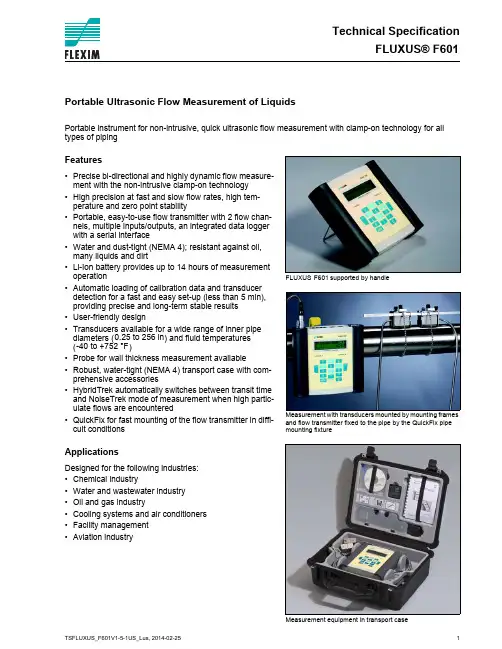
Technical SpecificationFLUXUS® F601FLUXUSsupported by handleMeasurement with transducers mounted by mounting frames and flow transmitter fixed to the pipe by the QuickFix pipe mounting fixtureMeasurement equipment in transport caseF601Portable Ultrasonic Flow Measurement of LiquidsPortable instrument for non-intrusive, quick ultrasonic flow measurement with clamp-on technology for all types of pipingFeatures•Precise bi-directional and highly dynamic flow measure-ment with the non-intrusive clamp-on technology •High precision at fast and slow flow rates, high tem-perature and zero point stability•Portable, easy-to-use flow transmitter with 2 flow chan-nels, multiple inputs/outputs, an integrated data logger with a serial interface•Water and dust-tight (NEMA 4); resistant against oil, many liquids and dirt•Li-Ion battery provides up to 14 hours of measurement operation•Automatic loading of calibration data and transducer detection for a fast and easy set-up (less than 5 min), providing precise and long-term stable results •User-friendly design•Transducers available for a wide range of inner pipe diameters () and fluid temperatures ()•Probe for wall thickness measurement available•Robust, water-tight (NEMA 4) transport case with com-prehensive accessories•HybridTrek automatically switches between transit time and NoiseTrek mode of measurement when high partic-ulate flows are encountered•QuickFix for fast mounting of the flow transmitter in diffi-cult conditionsApplicationsDesigned for the following industries:•Chemical industry•Water and wastewater industry •Oil and gas industry•Cooling systems and air conditioners •Facility management •Aviation industry0.25 to 256 in -40 to +752 °FFLUXUS® F601Technical Specification Table of Contents Function (3)Measurement Principle (3)Calculation of Volumetric Flow Rate (3)Number of Sound Paths (4)Typical Measurement Setup (5)Flow Transmitter (6)Technical Data (6)Dimensions (8)Standard Scope of Supply (9)Connection of Adapters (10)Example for the Equipment of a Transport Case (11)Transducers (12)Transducer Selection (12)Transducer Order Code (13)Technical Data (14)Transducer Mounting Fixture (17)Coupling Materials for Transducers (21)Connection Systems (22)Transducer Cable (22)Clamp-on Temperature Probe (optional) (23)Wall Thickness Measurement (optional) (24)Technical Specification FLUXUS® F601FunctionMeasurement PrincipleTransit Time Difference PrincipleIn order to measure the flow of a medium in a pipe, ultrasonic signals are used, employing the transit time dif-ference principle. Ultrasonic signals are emitted by a transducer installed on the pipe and received by a sec-ond transducer. These signals are emitted alternately in the flow direction and against it.As the medium in which the signals propagate is flowing, the transit time of the ultrasonic signals in the flow direction is shorter than against the flow direction.The transit time difference, ∆t, is measured and allows the flowmeter to determine the average flow velocity along the propagation path of the ultrasonic signals. A flow profile correction is then performed in order to ob-tain the area averaged flow velocity, which is proportional to the volumetric flow rate.Two integrated microprocessors control the entire measuring process. This allows the flowmeter to remove disturbance signals, and to check each received ultrasonic wave for its validity which reduces noise.HybridTrekIf the gaseous or solid content in the medium increases occasionally during measurement, a measurement with the transit time difference principle is no longer possible. NoiseTrek mode will then be selected by the flowmeter. This measurement method allows the flowmeter to achieve a stable measurement even with high gaseous or solid content.The transmitter can switch automatically between transit time and NoiseTrek mode without any changes to the measurement setup.Calculation of Volumetric Flow Rate= k Re . A . k a . ∆t/(2 . t fl )wherePath of the ultrasonic signal Transit time difference ∆t=volumetric flow ratek Re =fluid mechanics calibration factor A =cross-sectional pipe area k a =acoustical calibration factor ∆t =transit time difference t fl=transit time in the mediumV ·V ·FLUXUS® F601Technical SpecificationNumber of Sound PathsThe number of sound paths is the number of transits of the ultrasonic signal through the medium in the pipe. Depending on the number of sound paths, the following methods of installation exist:•reflect arrangementThe number of sound paths is even. Both of the transducers are mounted on the same side of the pipe. Correct positioning of the transducers is easier.•diagonal arrangementThe number of sound paths is odd. Both of the transducers are mounted on opposite sides of the pipe.•direct modeDiagonal mode with 1 sound path. This should be used in the case of a high signal attenuation by the medi-um, pipe or coatings.The preferred method of installation depends on the application. While increasing the number of sound paths increases the accuracy of the measurement, signal attenuation increases as well. The optimum number of sound paths for the parameters of the application will be determined automatically by the transmitter.As the transducers can be mounted with the transducer mounting fixture in reflect arrangement or diagonal ar-rangement, the number of sound paths can be adjusted optimally for the application.a = transducer distancenegative transducer distanceTechnical Specification FLUXUS® F601Typical Measurement Setuppower supply unit/battery charging unitExample of a measurement setup in reflect arrangementFLUXUS® F601Technical SpecificationFlow TransmitterTechnical DataFLUXUSF601designportablemeasurementmeasurement principle transit time difference correlation principle,automatic NoiseTrek selection for measurements with high gaseous or solid content flow velocity 0.03 to 82 ft/srepeatability 0.15 % of reading ±0.03 ft/smediumall acoustically conductive liquids with < 10 % gaseous or solid content in volume (transit time difference principle)temperature compensation corresponding to the recommendations in ANSI/ASME MFC-5.1-2011accuracy 1with standard calibration with advanced calibration (optional)with field calibration 2±0.5 % of reading ±0.03 ft/sflow transmitter power supply 100 to 240 V/50 to 60 Hz (power supply unit),10.5 to 15 V DC (socket at transmitter),integrated battery batteryLi-Ion, 7.2 V/4.5 Ahoperating time (without outputs, inputs and backlight): > 14 h power consumption< 6 W number of flow measuring channels2signal attenuation0 to 100 s, adjustable measuring cycle (1 channel)100 to 1000 Hzresponse time 1 s (1 channel), option: 70 ms housing material PA, TPE, AutoTex, stainless steel degree of protection NEMA 4dimensions see dimensional drawing weight 4.2 lbfixationQuickFix pipe mounting fixture ambient temperature 14 to 140 °Fdisplay2 x 16 characters, dot matrix, backlight menu languageEnglish, German, French, Dutch, Spanishmeasuring functions physical quantities volumetric flow rate, mass flow rate, flow velocity,heat flow (if temperature inputs are installed)totalizervolume, mass, optional: heat quantity calculation functions average, difference, sumdiagnostic functions sound speed, signal amplitude, SNR, SCNR, standard deviation of amplitudes and transit times data logger loggable values all physical quantities, totalized values and diagnostic values capacity> 100000 measured values1for transit time difference principle, reference conditions and v > 0.49 ft/s 2reference uncertainty < 0.2 %±1.6 % of reading ±0.03 ft/s ±1.2 % of reading ±0.03 ft/sTechnical Specification FLUXUS® F601 communicationinterface RS232/USBserial data kitsoftware (all Windows™ ver-sions)-FluxData: download of measurement data, graphical presentation, conversion to other formats (e.g. for Excel™)-FluxKoef: creating medium data sets-FluxSubstanceLoader: upload of medium data setsсable RS232adapter RS232 - USBtransport casedimensions19.7 x 15.7 x 7.5 inoutputsThe outputs are galvanically isolated from the transmitter. number see standard scope of supply on page 9, max. on request accessories output adapter (if number of outputs > 4)current outputrange0/4 to 20 mAaccuracy0.1 % of reading ±15 μAactive output R ext < 200 Ωpassive output U ext = 4 to 16 V, depending on R extR ext < 500 Ωfrequency outputrange0 to 5 kHzopen collector24 V/4 mAbinary outputoptorelay26 V/100 mAbinary output as alarm output-functions limit, change of flow direction or errorbinary output as pulse output-pulse value0.01 to 1000 units-pulse width 1 to 1000 msinputsThe inputs are galvanically isolated from the transmitter. number see standard scope of supply on page 9, max. 4 accessories input adapter (if number of inputs > 2)temperature inputtype Pt100/Pt1000connection4-wirerange-238 to +1040 °Fresolution0.01 Kaccuracy±0.01 % of reading ±0.03 Kcurrent inputaccuracy0.1 % of reading ±10 μApassive input R i = 50 Ω, P i < 0.3 W-range-20 to +20 mAvoltage inputrange0 to 1 Vaccuracy0.1 % of reading ±1 mVinternal resistance R i = 1 MΩFLUXUS F601FLUXUS® F601Technical Specification DimensionsTechnical Specification FLUXUS® F601 Standard Scope of SupplyFLUXUS® F601Technical Specification Connection of AdaptersExample for the Equipment of a Transport Caseserial data kitpower supply unit, mains cabletransducer mounting fixturemeasuring tapetransmittertransducersuser manual,Quick Start Guidecoupling compoundwall thickness probe (optional)QuickFix pipe mounting fixturetemperature probes (optional)TransducersTransducer Selectiontransducer order codeFSK 3.97.9141.7255.9 FSM2 3.978.7133.9FSQ0.390.98 5.915.7FSS0.240.39 2.80.20.4242040200inner pipe diameter [in] recommended possibleTransducer Order Code1, 2345, 67, 89 to 1112, 13no. of character t r a n s d u c e rt r a n s d u c e r f r e q u e n c y-a m b i e n t t e m p e r a t u r ee x p l o s i o n p r o t e c t i o nc o n n e c t i o n s y s t e m-e x t e n s i o n c a b l e/o p t i o ndescriptionFSset of ultrasonic flow transducers for liquids measurement, shear wave K0.5 MHzM 1 MHz Q 4 MHz S 8 MHzN normal temperature rangeEextended temperature range (shear wave transducers with trans-ducer frequency M, Q)NNnot explosion proof NLwith Lemo connectorXXXcable length in m, for max. length of extension cable see page 22 LClong transducer cable (only FSK)example FSM-NNNNL-000shear wave transducer 1 MHz, normal temperature range,connection system NL with Lemo connector--/Technical DataShear Wave TransducersShear Wave TransducersShear Wave Transducers (extended temperature range)Transducer Mounting FixtureOrder Code1, 234567 to 9no. of character t r a n s d u c e r m o u n t i n g f i x t u r et r a n s d u c e r-m e a s u r e m e n t a r r a n g e m e n ts i z e-f i x a t i o no u t e r p i p e d i a m e t e rdescriptionFS mounting framesLM ladder chain mounting accessory VP portable Variofix TB tension beltsWLtransducer box for WaveInjectorA all transducersK transducers with transducer frequency K M transducers with transducer frequency M Q transducers with transducer frequency Q Stransducers with transducer frequency SD reflect arrangement or diagonal arrangement/direct mode Rreflect arrangement S small Mmedium C chains Nwithout fixation L080.5 to 8 in L220.5 to 22 in 0100.39 to 3.9 in 0250.39 to 9.8 in 0550.39 to 21.7 in 150 2 to 59.1 in 2102 to 82.7 inexample VPA-DM-C055portable Variofix and chains --ladder chain mounting accessory LMTechnical Specification FLUXUS® F601Coupling Materials for TransducersTechnical Datanormal temperature range(4th character of transducer ordercode =N)extended temperature range(4th character of transducer ordercode =E)WaveInjector WI-400< 212 °F < 338 °F< 302 °F < 392 °F< 536 °F536 to 752 °Fcoupling compound type N coupling compound type Ecoupling compound type E coupling compound type E or Hcoupling foil type A and coupling foil type VTcoupling foil type B and coupling foil type VTtypeorder code ambient temperature materialremark°Fcoupling compound type N990739-1-22 to +266mineral grease paste coupling compound type E990739-2-22 to +392silicone paste coupling compound type H990739-3-22 to +482fluoropolymer paste coupling foil type A 990739-7max. 536lead coupling foil type B990739-8> 536 to 752silvercoupling foil type VT 990739-014 to +392fluoroelastomerfor transducers with transducerfrequency G, H, K990739-6for shear wave transducers with transducer frequency M, P990739-14for shear wave transducers IP68 and Lambwave transducers with transducer frequency M, P990739-5for transducers with transducer frequency Qcoupling foil not to be used for transducer mounting fixture with magnetsFLUXUS® F601Technical SpecificationConnection SystemsTransducer CableTechnical Datatransducer frequency (3d character of transducerorder code)G, H, K M, P Q S N Lx y l 1xy l 1x y l 1x y l cable length ft69≤ 8266≤ 8263≤ 8233≤ 65cable length (option LC)ft622≤ 82---------1> 82 to 328 ft on requestx, y = transducer cable length l = max. length of extension cabletransducer cableextension cabletype169925511750standard length ft see table above 1632max. lengthft -see table above 32ambient temperature °F-67 to +392-13 to +176< 144sheath materialstainless steel 304--outer diameter in0.31--cable jacket materialPTFE TPE-O PE outer diameter in 0.110.310.24thickness in0.010.02color brown black black shieldxxx-Technical Specification FLUXUS® F601Clamp-on Temperature Probe (optional)Technical DataConnectionTemperature ProbeConnectorCabletechnical type PT13N PT13N PT13F PT13F order code 670413-1670412-1670413-2670412-2design short response timetypePt10002x Pt1000 matched according to EN 1434-1Pt10002x Pt1000 matchedaccording to EN 1434-1connection4-wire 4-wire measuring range °F-22 to +482-58 to +482accuracy T ±(0.27 °F + 2 . 10-3 . (|T [°F]| - 32 °F)), class A±(0.27 °F + 2 . 10-3 . (|T [°F]| - 32 °F)), class Aaccuracy ∆T-≤ 0.1 K(3 K < ∆T < 6 K), more corresponding to EN 1434-1-≤ 0.1 K(3 K < ∆T < 6 K), more corresponding to EN 1434-1response times508housingaluminum PEEK, stainless steel 304, copperdegree of protection NEMA 4NEMA 4weight (without con-nector)lb0.6 1.10.7 1.4fixationclamp-onclamp-onaccessoriesthermal conductivity paste 392 °Fx x thermal conductivity foil 482 °Fx x plastic protection plate, insulation foam -xdimensions length l in0.590.55width b in 0.59 1.18height hin0.79 1.06dimensional drawingA Bpin cable of temperature probeextension cable1white/blue blue 2red/bluegray3, 4, 5not connected6red red 7whitewhite8not connectedcable of temperature probe extension cabletype4 x 0.25 mm² black or white LIYCY 8 x 0.14 mm² gray standard length ft 916/32/82max. length ft-656cable jacketPTFEPVCABred/blueredwhite/bluewhiteWall Thickness Measurement (optional)The pipe wall thickness is an important pipe parameter which has to be determined exactly for a good mea-surement. However, the pipe wall thickness often is unknown.The wall thickness probe can be connected to the transmitter instead of the flow transducers and the wall thickness measurement mode is activated automatically.Acoustic coupling compound is applied to the wall thickness probe which then is placed firmly on the pipe.The wall thickness is displayed and can be stored directly in the transmitter.Technical DataCabletechnical type DWR1NZ7measuring range 1in 0.04 to 9.8resolution in 0.0004accuracy1 % ± 0.004 in medium temperature °F-4 to +392,short-time peak max. 932сable type 2616lengthft41 The measuring range depends on the attenuation of the ultrasonic signal in thepipe. For strongly attenuating plastics (e.g. PFA, PTFE, PP) the measuring range is smaller.type2616ambient temperature °F<392cable jacket materialFEP outer diameter in0.2color black shieldxDWR1NZ7FLEXIM AMERICAS Corporation Edgewood, NY 11717USATel.:(631) 492-2300Fax:(631) 492-2117internet: e-mail:*****************1-888-852-7473 Subject to change without notification. Errors excepted. FLUXUS® is a registered trademark of FLEXIM GmbH.。
便携式露点仪型安全操作及保养规程1. 前言本文档讨论的是便携式露点仪型安全操作及保养规程。
在使用该设备时,用户应遵循以下安全操作规程,以确保使用过程中的安全和设备的可靠性。
2. 设备概述便携式露点仪是一种用于测试露点的设备,主要包括以下几部分:•型号和序列号标签•背包•露点仪主体•传感器指示器•外部气体钳•电池计量器在使用设备之前,需要详细了解设备部件和操作方法,以避免不当操作和设备损坏。
3. 安全操作规程在使用便携式露点仪时,需要遵循以下安全规程。
3.1 使用环境1.请在通风良好的室内或户外使用设备。
在密闭环境下使用设备会使空气中的湿度升高,从而影响测试准确性。
2.在使用设备时,应确保测试环境中不存在易燃、易爆或有害气体。
如果存在,应事先将这些气体排出或使用配套气体净化器。
3.2 操作前准备1.在操作设备之前,请先阅读设备说明书,并确认是否需要进行校准。
2.检查设备各部分是否完好,特别是检查传感器是否干净,以确保测试数据的准确性。
3.确认设备所采用的气体和供气压力是否正确。
如果使用现场气体时,应使用配套的气体管路和外部气体钳。
3.3 操作细节1.在功能设定时,请确认功能设定参数,如试样量等。
如果不确定,请参考相关说明书或咨询专业人士。
2.在使用过程中,请勿将传感器插入水或其他液体中。
在进行露点测试时,应确保传感器处于干燥状态。
3.如果设备出现任何异常情况,如传感器指示异常等,应立即停止测试,检查设备并联系设备供应商或维修人员。
3.4 设备保养1.在使用完设备后,请将设备置于干燥处。
2.在存储设备时,请勿长时间存放在高温、潮湿环境中。
3.定期对设备进行维修和保养,确保设备良好的性能和使用寿命。
4. 总结本文档讨论了便携式露点仪型安全操作及保养规程。
在使用该设备时,应遵循相关安全规程,确保设备正常运行和测试准确性。
同时,也需要注意设备的保养,以延长设备使用寿命和性能。
如果在使用设备时遇到任何问题,请及时联系设备供应商或维修人员。

CERMAX ISIssue 11, March 2003 Manual No.97046 43Pages1.1 (4)1.2 (5)1.3 ATEX (5)2.CERMAX IS (7)2.1 (7)2.2 (7)2.2.1 (7)2.2.2 (7)2.3 (8)2.4 (8)2.4.1 (8)2.4.2 (9)3. CERMAX IS (10)3.1 (10)3.2 (11)3.3 (11)3.3.1 (12)3.4 (12)3.4.1 (12)3.4.2 DEW POINT( ) (13)3.4.3 PPM(W)( ) ( ) (14)3.4.4 PPM(V) 1b/mmscf g/m3 %RH (14)3.5 (14)3.5.1 (15)3.5.2 (15)3.5.3 (15)3.5.4 (16)3.5.5 (16)3.5.6 (17)3.5.7 (18)3.6 (19)3.6.1 (Test No.) (20)3.6.2 (20)3.6.3 (20)3.6.4 (21)3.6.5 (21)3.6.6 (21)3.6.7 (21)3.6.8 (22)3.6.9 (22)3.6.10 (23)3.6.11 (23)3.6.12 (23)3.7 (24)3.7.1 (25)3.7.2 (26)3.8 (27)3.9 (29)4.1 (31)4.2 (31)4.3 (32)4.4 (32)5. (33)5.1 (33)5.2 CERMAX IS (33)5.2.1 (34)5.2.2 (34)5.3 (35)6. (38)1 (39)2 MICHELL (40)3 CERMAX IS (42)1.CERMAX IS MICHELL LCD -100 20 -120o C~+30o CCERMAX IS CERMAX IS CERMAX IS CERMAX IS DISPLAY 3.6CERMAX IS CERMAX IS ON ( 4.3 )1.1(NPL) UKAS -75 ~+20ºC( 0179) (NIST)MICHELL MICHELL MICHELL 5.01.2BS EN ISO 9001:1994 Baseefa (2001)B.S.I.&Baseefa(2001)1.3 ATEXCERMAX IS ATEX (94/9/EC) Baseefa (2001) Ltd (Notified body 1180) BS EN 50 014T bs en 50 020 C.E.N.E.L.E.C. Ex II 1G EEx ia IIC 155o C (T3) Baseefa 03ATEX0090XCERMAX IS ATEX (94/9/EC) ATEX worker protection Directive (1999/92/EC)( )(Flat Battery)CERMAX IS(Logging memory full or incorrect instrument setup.) CERMAX IS CERMAX IS/ (Sensor over/under range or inaccurate sensor measurement)1)2)3)4.2.CERMAX IS2.1CERMAX IS2.2CERMAX IS2.2.1CERMAX IS 4.2CERMAX IS SWAGELOK 1/8” 0.5~5Nl/min 30MPa(300barg) 90o2.2.2on/off (Default) (Previous)3. CERMAX IS2.3CERMAX IS field mode laboratory mode 3.7 3.7.10 015 2 2 -80CERMAX IS 2LCD2.4CERMAX IS2.4.1CERMAX IS 4CERMAX ISCERMAX ISCERMAX IS CERMAX IS2.4.2CERMAX IS RS232 3.6 3.7 3 CERMAX IS 9 D3. CERMAX IS3.110 USER SETUP DEFAULT( ) PREVIOUS( )DEW POINT,OVER ICENONEo C o FpsigDEFAULT/PREVIOUSCERMAX ISSENSOR ID C123 C45 CALIBRATED 14:04:99SOFTWARE VERSION B1.80.00 I.S.COPYRIGHT MICHELL INSTRUMENTS LTD.1aUSER SETUP: DEFAULT PREVIOUSBATTERY CHECK OK1b3.2(MAIN DISPLAY) (AUXILIARY DISPLAY)2Stable DP @ Pressure 10.2ºC10.2 °C DPWARNING - LOW BATTERY33.7DATE 14:04:97 TIME 14:25NO LOGGED DATA AVAILABLE43.33CERMAX ISMain Display Main option3.3.1MENU3.4.DP PPM(V)PPM(W)g/m 3Ib/mmscf %RH 3.4.1MAIN DISPLAY AUX DISPLAY LOGGING DP °C °F K OVER WATER PPM(V) PPM(W)5aMAIN DISPLAY AUX DISPLAY LOGGINGg/m 3lb/mmscf %RHMAIN DISPLAY AUX DISPLAY LOGGING DP °C °F K OVER WATER PPM(V) PPM(W)63.4.2 DEW POINT( )o C o F KMAIN DISPLAY AUX DISPLAY LOGGING DP °C °F K OVER WATER PPM(V) PPM(W)7 o F0o C OVER WATER0o C OVER WATERMAIN DISPLAY AUX DISPLAY LOGGING DP °C °F K OVER WATER PPM(V) PPM(W) 83.4.3 PPM(W)( ) ( )PPM(W)MAIN DISPLAY AUX DISPLAY LOGGING DP PPM(V)PPM(W) N 2 AIR CO 2 H 2 SF 69 PPM(W) 3.4.4 PPM(V) 1b/mmscf g/m 3 %RH PPM(V) 1b/mmscf g/m 3 %rh3.5%rh%rhAuxiliary OptionsMain Option NoneSet Temp Set Press SensorDisplay DPxPPM(V) xPPM(W) xg/m 3x x x lb/mmscf x xx %RHx xxNone. ( ) NONE( ) 21oCSET TEMP CERMAX IS %rhSET PRESS ( ) Set PressSENSOR. DISPLAY.AUX DISPLAY LOGGING MAIN DISPLAY NoneSet Temp Set Press10aAUX DISPLAY LOGGING MAIN DISPLAY Set Press Sensor Display10b ( ) 3.5.1AUX DISPLAY LOGGING MAIN DISPLAY NoneSet Temp °C °F K Set Set Press11 3.5.2%rh (Set temp)(Set Temp) (Set)AUX DISPLAY LOGGING MAIN DISPLAYNoneSet Temp °C °F K Set Set Press12 F 3.5.3(Set)Maximum allowable values Minimum allowable values +200°C -100°C +392°F -148°F 473K +173KAUX DISPLAY LOGGING MAIN DISPLAY NoneSet Temp°C °F K Set -25 Set Press13 -25 3.5.4%rh Set Press PSIG BARG barkPa kPa kPa(Set Press) (Set)AUX DISPLAY LOGGING MAIN DISPLAY NoneSet TempSet Press PSIG BARG kPa Set 100014 BARG 3.5.5Maximumallowable values Minimum allowable values 5880 PSIG 0 PSIG 400 BARG 0 BARG 40,000 kPa 50 kPaAUX DISPLAY LOGGING MAIN DISPLAY NoneSet TempSet Press PSIG BARG kPa Set 3817 381b/mmscf g/m 3 CERMAX IS 1b/mmscf CERMAX IS 1958 kPa bar0 50psig 10 psig 75~300 psig 25 psig 350 500 psig 50 psig 600 1000 psig 100 psig 1200 1500 psig300 psigCEREMAX 13psig bar kPa 10psig CERMAX IS 540psig 500psig 3.5.6( 3.5.4) AUXILIARY DISPLAY( ) (Sensor)%RHg/m 3 lb/mmscf AT PRESSAUX DISPLAY LOGGING MAIN DISPLAY Set Temp Set PressSensor At Press At Atm16 3.5.7(Auxiliary Display)(Sensor)%RHg/m 3 lb/mmscf PRESSAUX DISPLAY LOGGING MAIN DISPLAY Set Press SensorDisplay Press DP17DP @ Pressure 36.5°C10.2°C DPFIELD MODE CAL DUE 04:9818Set Pressure 550 PSIG 10.2°C DPFIELD MODE CAL DUE 04:98233.6CERMAX IS 1000 10000 PC 3.7(LOGGING)Test No. Interval SamplesStart/StopLOGGING MAIN DISPLAY AUX DISPLAY Test No. TextInterval.20aLOGGING MAIN DISPLAY AUX DISPLAYIntervalSamplesStart/Stop20b ( )3.6.1 (Test No.)0 TEST NO 0 Test No.3.6.215 /-TEXT3LOGGING MAIN DISPLAY AUX DISPLAYTest No.Text QUALITY TESTS 3THIS IS MY TESTInterval.213.6.3LOGGING MAIN DISPLAY AUX DISPLAYTest No.TextInterval 1 2 3 5 10 15 30 45 60 mins223.6.4999 10000LOGGING MAIN DISPLAY AUX DISPLAY Test No. TextInterval Samples 2523 3.6.53.6.6START( )LOGGING MAIN DISPLAY AUX DISPLAY Interval SamplesStart/Stop Stop Start Delay Start 00:0024 3.6.7(Delay Start) (24 ) 8:00am 2 30 10:30 (Delay Start) 9 17:00(5:00pm) (Delay Start)Start/Stop(Delay Start)15LOGGING MAIN DISPLAY AUX DISPLAY Interval SamplesStart/Stop Stop Start Delay Start 14:3025 14:30(2:30pm) 3.6.8CERMAX ISStart/Stop STOPLOGGING MAIN DISPLAY AUX DISPLAY SamplesStart/Stop Stop Start Delay Start 14:3026 3.6.9/ ( )Date 14:04:97 Time 14:48NO LOGGED DATA AVAILABLE273.6.10( 3.7 PC )’None’ / (Stable/Responding) 0= (Stable) 1= (Responding) 3.6.114Enter Sample No:5 14:04:97 17% No Time Frostpoint°C PSIG 75 16:23 -15.38 0.0 76 16.24 -15.40 0.029 5 3.6.12Memory gaugeLOGGING MAIN DISPLAY AUX DISPLAYTest No. 5 TextInterval30Test Pt:5 QUALITY TEST 1 14:04:97 9% No Time Frostpoint°C PSIG 0 16:23 -23.39 0.0 1 16.24 -24.400.0313.7CERMAX IS RS232 9600baud 8data bits 1 start bits 1 stop bit no parity IDCERMAX IS COPYRIGHT MICHELL INSTRUMENT LTD. CERMAX IS UNIT ID FREDSERIAL NO.C123C45SOFTWARE VERSION R190.00HELPCLCK? READ THE REAL TIME CLOCK DATE=xx:xx:xx SET DATE TIME=xx:xx:xx SET TIME LANG=US US SETUP LANG=UK UK SETUPKDLY=xx SET KEY REPEAT DELAY IN 10mS UNITS (DEFAULT 100mS) KRPT=xx SET KEY REPEAT RATE IN 10mS UNITS (DEFAULT 100mS) ERAS CLEAR THE LOGGING MEMORY FIELD SPOT CHECK MODE LABUSELABORATORY MODEID= ENTER A MACHINE ID (MAXIMUM 20 CHARACTERS) LOAD DOWNLOAD LOGGED DATA TO TERMINAL 3.7.1CLCK? DATE IS 16:04:97 TIME IS 16:43:15 DATE=17:04:97 DATE IS 17:04:97TIME=10:30:00 TIME IS 10:30:00 LANG=UK or LANG=US LANGUAGE = UK or LANGUAGE = US FIELD UNIT CONFIGURED FOR SPOT CHECKLABUSE UNIT CONFIGURED FOR EXTENDEDMEASUREMENT MODECERMAX IS 10KDLY=10INITIAL KEY REPEAT DELAY SET TO 100 mS100CERMAX IS 10 100 KRPT=10 KEY REPEAT INTERVALSET TO100 mSPCLOAD DOWNLOADING LOGGINGFILES - PLEASE WAIT…DOWNLOAD SUCCESSFULCERMAX IS ERAS CLEARING THE LOGGINGMEMORY WILL TAKE AFEW SECONDS - PLEASEWAIT….LOGGING MEMORYCLEAREDID=FRED Unit ID is FREDLOCK OKUNLOCK OK3.7.2PC COM1 CERMAX IS RS232CERMAX ISWICDOWS 95 HYPER TERMINALHYPER TERMINAL CERMAX ISHYPER TRMCERMAX ISOKConnect COM1OKCOM1Baud 9600Data bits 8Parity NONEStop bits 1Flow control HardwareOKUNIT ID FREDTest Pt:0 MY TEST 15:04:97No Date Time LB/MMSCF PSIG0 15:04:97 14:59 2.30 1000.01 15:04:97 15:00 2.31 1000.0||8 15:04:97 15:02 2.28 1000.09 15:04:97 15:03 2.28 1000.03.8Cermax ISUKASTest HygrometerGenerated Dew point°CDew pointTemperature°CSensorTemperature°CCorrectionRequired°CExpandedUncertainty°C-39.89 -40.11 -20 +0.22 ±0.26-20.10 -20.31 0 +0.21 ±0.220.39 0.20 21 +0.19 ±0.18Generated Dew point°C Instrument Display°C-40.1 -40.2-20.1 -20.10.2 0.1Cermax IS(Calibration Correction)(Calibration Correction)Ref DP( ) ( )Cermax IS DP(Cermax IS ) Cermax IS ) +20o C~-100o C dp 13 Ref DP Cermax IS DP-20o C~+10o C Ref DP Cermax IS DP3.9CERMAX IS1.2.CERMAX IS 2.4.112 141.2. CERMAX IS LOW BATTERY WARNING MICHELL3.4.4.4.14.2CERMAX ISMICHELLCERMAX IS 1/8” PTFE0.5~5L/min4.34.2CERMAX IS 15~90 CERMAX ISON RESPONDINGRESPONDING STABLE( )84.4CERMAX IS MICHELLCERMAX IS IS5.5.1CERMAX IS UKASCermax IS Cermax ISCERMAX ISCERMAX IS CERMAX IS 5.25.2 CERMAX ISCERMAX ISMICHELL CERMAX IS5.2.1CERMAX IS1. RS2322. 8 363.CERMAX IS4. CERMAX IS 3 3 365.6. 1/8” CERMAX IS7. CERMAX IS MICHELL5.2.21. 1/8”2.3. 1/8”4.5. CERMAX IS6.85.3EPROM EPROM EPROM EPROM5.3.1 2.15.3.2 IC145.3.3 EPROM IC145.3.4 85.3.5SETUPMARKET=USLANG=US5.3.6 CERMAX ISMICHELL36 Cermax IS6.MICHELL3161/8” SWAGELOK240 64 LCD4 40 LCD-100o C~+20 o C-120o C~+30o C-60~+20o C, 1o C-100~60o C; 2o C0.1 o C 3o C , o F, Kppm(v)ppm(w)gm-3lb/mmscf0~20mA 4~20mA10,000 RS2326V2412 14250mm 300mm 150mm3kgIP65 NEMA4-20~+50o C-40~+70o C30MPa0.5~5L/min1MICHELL CERMAX IS MICHELL2 MICHELL Michell Instruments LtdNuffield Close, Cambridge, CB4 1SS, UK Tel: +44 (0)1223 434800Fax: +44 (0)1223 434895email: i nfo@web: Michell Instruments GmbH Industriestrasse 27, D-61381 Friedrichsdorf GermanyTel: +49 6172 5917-0Fax: +49 6172 591799email: info@michell.deweb: www.michell.deMichell Instruments SARL4 rue du Docteur Heulin, 75017 Paris FranceTel: +33 (0)1 42 26 01 24Fax: +33 (0)1 42 26 01 37email: i nfo@michell.frweb: www.michell.frMichell Instruments BVKastanjelaan 18M, 2982 CM RidderkerkThe NetherlandsTel:+31 (0)180 466460Fax:+31 (0)180 415623email: info@michell-instruments.nlweb: www.michell-instruments.nlMichell Italia SRLVia Capecelatro 10, 20148 MilanItalyPhone: +39 (0) 024 047194Fax: + 39 (0) 024 *******E-mail: info@michell.itWeb: www.michell.itMichell Instruments Shanghai OfficeUnit A9112, Jia Hua Shang Wu Zhong Xin 808 Hong Qiao Lu, Xu Hui, Shanghai 200030 P R ChinaPhone: +86 (0)21 6448 0152Fax: +86 (0)21 6447 9417E-mail: michellasia@Michell Japan KKMusashino Center Building, 1-19-18 Nakacho, Musashino Tokyo 180- 0006JapanPhone: +81 422 502600Fax: +81 422 521700E-mail: NokeiKWN@web: 3 CERMAX IS1) 1 2L/mina) CERMAX IS b) CERMAX IS,2) Field Mode( ) Lab Mode( ) USER SETUP:DEFAULT FIELD MODE LAB MODE3)RESPONDINGDEW POINT AT ATMOSPHERIC CERMAX IS4) 3 0.4 STABLE 5~105)MICHELL +86 0 21 64479417 64480152 michellasia@。
OWNER’S MANUAL PRO-68SE LASER-RADAR DETECTORWHISTLER FEA TURESPRO-68SE Accessories:•Windshield Bracket Kit •Straight Power Cord •Non-Skid Dash Pad •Hardwire Kit12681091171312141.Bracket Release Button –Provides quickand easy release of the mounting bracket.2. Speaker –Provides distinct audio warningsfor X, K, Ka band radar, safety radar and laser.3.Mounting Bracket Location –Slot holdsmounting bracket firmly.4.Radar Antenna –Compact, high-efficiencyantenna receives radar signals.5.Front Laser Antenna –High gain optical lensprovides increased sensitivity and field of view for leading-edge laser detection.6. Rear Laser Antenna –An integrated opticalwave-guide provides superior detection of laser signals transmitted from behind.7.City Button -Reduces the annoyance offalse alerts typically encountered in urban driving areas.8.Quiet Button - Pressing QUIET before asignal is detected engages Auto Quiet Mode which automatically reduces the audio level after the initial warning to a low audio level setting. Pressing QUIET during a radar/laser encounter silences audio alerts,while allowing visual alerts to keep you informed.9. Power/Volume -Turns unit on/off andadjusts audio level.10. Dim/Dark Button -Engages Dim/Darkmode display options.11. Menu Button -Enters option select mode.12. Numeric Icon Display –Provides distinctvisual confirmation of signals detected, signal strength, and engaged modes of operation.13. Low Profile Alert Periscopes -Provides anadditional attention getting visual alert.14.Power Jack –Provides connection for thepower cord.FEA TURE DESCRIPTIONSMounting Guidelines•Mount the unit as low as possible near the center of the windshield.•Do not mount your unit behind wipers,ornaments, mirrored sunscreens, etc. These obstructions have metal surfaces which can affect radar and laser signals and reduce critical warning time. (Regular tinted glass does not affect reception.)•Some windshields have an Instaclear ™orElectriclear ™type coating, which affects radar signals.Consult your dealer or the vehicle’sowner’s manual to determine if your windshield has this coating.•Avoid placing unit in direct contact with wind shield.•To reduce the possibility of theft, conceal your unit when not in use.Windshield Mounting•Install the two suction cups and rubber bumper onto the bracket by fitting them into their holes.•Press the suction cups onto the windshield at the location you have chosen. (Image A)Important: S ome newer cars have a plastic safety coating on the inside of the windshield. The windshield bracket may leave permanent marks on this type of surface.T o find out if your vehicle has this type of windshield,check the vehicle’s owner’s manual or ask your dealer .INST ALLATIONWindshield MountingWe recommend that you do not leave the suction cup bracket on the windshield in direct sunlight. If the detector is removed, this may cause blistering of the dash in some vehicles.•Slide the detector onto the bracket until it locks intoplace. (Image B)•If necessary , the unit may be leveled by bending the windshield bracket. Press the bracket release button and remove the detector before bending.Power Cord Connection•Plug the small end of the power cord into the unit’s power jack.•Plug the large end into the vehicle’s cigarette lighter .N o t e :Cord fits tightly into detector. When installing the cord, expect some resistance.Fuse ReplacementThe lighter socket plug is equipped with areplaceable 2 amp, 3AG fuse located behind the silver tip. To replace the fuse, carefully unscrew the tip of the plug.I m p o r t a n t :Unscrew slowly. The tip contains a spring which may fly out when disassembling.Insert the new fuse with the spring and screw on the tip. With use, screw cap on plug may loosen.Retighten occasionally.Unscrew the tip of the lighter socket plug carefully when replacing the 2 amp fuse.INSTALLATIONRubber Bumper(Image B)Power On and Self-TestEach time your Whistler detector is turned on, an automatic self-test sequence confirms that the speaker and display are functional.•Press Power. Display indicates (in order):1. X-Band2. K-Band3.Ka-Band SER 6. P (POP)Setting SaverSetting Saver saves your personalized settings so that when the detector is turned off and then on again, you do not have to re-enter them.Feature Engaged Confirmation Each time a button is pressed one beep confirms feature “on”, two beeps confirm feature “off”.Audio Level AdjustmentThe audio levels can be adjusted high to low or low to high.•Rotate Power/Volume button back to increase audio level.•Rotate Power/Volume button forward to decrease audio level.As audio level is adjusted, beeps are provided and the display indicates volume level.Self T est MuteSimply press the Quiet button during the self-test sequence to cancel the self-test audio. This will not affect radar/laser alerts. To restore the self-testaudio, simply press the Quiet button during the next self-test.Quiet ModeQuiet cancels audio during an alert and any new alert within 20 seconds. After 20 seconds of no alerts, the audio is restored for any new alerts.• Press Quiet to cancel the audio.• Press Quiet a second time during an alert torestore the standard audio alert pattern; or turn the unit off, then on.OPERATIONOPERATIONAuto Quiet ModeAuto Quiet reduces the selected audio level to level (1) approximately 5 seconds after a radar or safety radar signal is detected. The alert for any new signal within 20 seconds will resume at level (1). Auto Quiet does not affect laser alerts.•Press Quiet button (before a signal is detected) to engage Auto Quiet.•Once the Auto Quiet mode is engaged, youmay cancel the audio alarm by pressing Quiet.•Press Quiet (when the unit is not alarming) tocancel Auto Quiet mode.Stay Alert FeatureThe Stay Alert Feature is designed to test a driver’s alertness. To engage (when unit is not alarming) :•Press and hold City for approximately 2 seconds. Release button during or immediately after the alert is given.The “H” or “C” will flash indicating Stay Alert is activated. Within 30-60 seconds two beeps are sounded; to show alertness, the driver must press either the Menu, City, or Quiet button within 3-5 seconds.If the button is pressed within 3-5 seconds, the cycle is repeated. If a button is not pressed with in 3-5 seconds, the alarm sounds and the entire display will flash.•Press Power to exitWARNING Stay Alert is NOT intended as a substitute for adequate rest. Y ou should NOT operate a vehicle if you are drowsy. During extended periods of vehicle operation,you should take frequent breaks. Improper reliance on the Stay Alert feature may result in vehicle damage, personal injury or death.NEVER OPERATE A VEHICLE IF YOU ARE DROWSY.Low Profile Alert PeriscopesWhistler’s Low Profile Alert Periscopes provide anadded attention getting visual alert. The two extraLED’s flash on and off when the unit alarms toprovide a unique visual alert. This alert can beprogrammed through the Option Select Mode tobe: ON, OFF, or FLASHING during alerts.City/City 1/City 2 ModesWhistler’s Three Stage City Mode is designed toreduce the annoyance of automatic dooropeners, intrusion alarms and other deviceswhich share frequencies with police radar.Generally, X band is used for these devices.• Press City to cancel Highway Mode andengage City Mode.• Press City button again to enter City 1 Mode• Press City button again to enter City 2 Mode• Press City a fourth time to cancel City 2 Modeand return the unit to Highway Mode.In City Mode, weak speed/safety radar signalsgive an initial alarm of two beeps, and thenremains quiet unless the signal becomes verystrong. When the signal strength increases, twoadditional beeps are provided. City 1 and City 2Modes operate the same as Highway Mode, butin City 1 Mode, X band requires a strongersignal to alert. In City 2 Mode, X-band is notdetected.Caution:Some towns/small cities may still beusing X band radar. City Modes do not changethe audio alert for laser.OPERATIONHighway ModeHighway mode provides full audio warnings anytime radar (X, K, Ka, Safety Radar) or lasersignals are detected, and is recommended foropen road driving.Teach/Tutorial ModeProvides simulated alerts for each type of signal.•Press City and Quiet buttons simultaneouslyand release.•Press Power to exit.Dim/Dark ModesDim/Dark Mode reduces the illumination of thedisplay• Press and release the Dark button to reduceillumination to a dim setting.• Press and release the Dark button a secondtime to engage Dark Mode. The displayillumination is further reduced.Dim or Dark can be engaged during an alert. InDark Mode, the display goes dark for as long asa signal is being detected and 20 seconds after,then the display returns to the dimmer setting.• Press and release the Dark button a third timeto restore the display to full illumination.OPERATIONSafety Warning System ™In communities where transmitters are located,the Safety Warning System ™displays over 60text messages. When Safety Radar is detected aunique audio alert is soundedand displays a to indicate an SWS ™ message has been received.Note: Not all areas have Safety Warning System ™transmitters.Filter ModeThere are times when another radar detector can emit the same frequency as police radar and can cause your detector to falsely alarm. The Whistler Filter Mode options provide a method to reduce the occurrences of these situations.Filter:Allows for normal filtering.Filter 1:Provides an extra step to analyze the signal that may come from other detectors.Filter 2:Provides further signal analysis before alerting.Filter is the factory default and should provide adequate filtering for most conditions.Filter Mode does not override Highway or City settings. See Option Select Mode to change Filter settings.Vehicle Battery Saver ModeThe Vehicle Battery Saver Mode automatically shuts off your detector within 6 hours. The timer is reset if the detector is turned off, unplugged or any button is pressed before the 6 hours have expired. The detector will alert you with an audible and visual warning before it shuts off. During this warning you can reset the timer by pressing any button.If the unit has automatically turned itself off,press the Power button to turn the unit back on.You can manually engage the Vehicle Battery Saver Mode by pressing and holding the City button until one beep is heard.OPERATION OPERATIONOption Select ModePress the Menu button to enter Option Select Mode. Each press of the Menu button changes to the next selectable feature.The Dark (DD ) button and the Quiet (Q Q ) button turns the feature ON/OFF or Blinking. The decimal point illumination indicates whether a feature is on or off. A button must be pressed within 20 seconds or Option Select Mode will automatically be exited.OPERATIONFeature: Display: To Change: Option:POP ™ Mode AlertsBecause POP ™Mode radar utilizes the sameK or Ka band frequencies, POP ™Mode Alerts will be displayed as regular radar alerts.LASER/RADAR ALERTSSpeed Radar Audio/Visual AlertsWhen X, K or Ka is detected, the band ID and signal strength are displayed. The audio alert is continuous and has a geiger counter-like pattern. The faster the beep, the closer or stronger the radar source.Laser Audio/Visual AlertsWhen a laser signal is detected the audio alert is continuous for a minimum of 3 seconds. •The unit displays an “L”.Pulse Protection ®Pulse (or instant-on) radar is more difficult to detect than conventional radar because itremains ‘off’ until activated to measure the speed of a targeted vehicle.When a pulse type transmission is detected, your Whistler detector sounds an urgent 3-second audio warning and the unit displays a “P”. After the 3-second pulse alert, the standard alert pattern continues for as long as the signal is present.It is important to respond promptly to a pulse alert, since warning time may be minimal.POP ™ MODE ALERTSAlert PriorityWhen two or more signals are received at the same time, the alert priority is:ser2.Speed Radar3. Safety Radar Example:If X band is alerting, then suddenly a laser signal is detected, the laser warning will override the X band alert.LASER/RADAR ALERTSReset FeaturesAll user features can be reset to factory settings.•Unplug Power Cord from unit.•Press and hold Power and Quiet buttons.•Plug Power Cord into unit.• Wait for 2 beeps.•Release Power and Quiet buttons.Unit is now reset to the following features and settings.Default factory settings are:1.Audio to level (4).2.Displays “H”3.Auto Quiet Mode OFF .4.Safety Radar OFF .5.Dim/Dark Mode to full illumination.6.All Radar Bands ON.7.LED Periscope to Blink.8.POP ON.9.Filter ON.10. Laser ON.TROUBLESHOOTINGYour Whistler detector is expertly engineered and designed to exacting quality standards to provide you with reliable, trouble-free operation.If your unit has been correctly installed following the guidelines in this manual, but is not operating optimally, please refer to the troubleshooting guide below.PROBLEM: No display or audio.•Check fuse in Whistler plug; replace if necessary with a 2 amp, 3AG type.•Check fuse for lighter socket; replace if necessary.•Make sure lighter socket is clean.RESET FEATURESPROBLEM: Unit alarms when vehicle hits bumps.•Check for loose lighter socket; tighten and clean.•Check connections at both ends of power cord. Substitute another cord to determine if cord is defective. Return defective cord to the factory.TROUBLESHOOTINGCare And MaintenanceDuring the summer months, avoid prolonged exposure to direct sunlight by removing your unit from the dash when your vehicle is parked for an extended period of time. Do not spray water,cleaners, or polishes directly onto the unit. The spray may penetrate through the openings and damage the unit. Also, do not use any abrasive cleaners on the unit’s exterior.ARE DETECTORS LEGAL?In Most States YES!Laser-Radar detectors are legal in every state for automobiles and light trucks (under 10,000 lbs.)except Virginia and Washington, D.C., which have local regulations restricting the use of radar receivers in any vehicle.The Federal Highway Administration (FHWA)passed a nationwide regulation, effectiveJanuary 1994, which prohibited radar and laser detector use in vehicles over 10,000 lbs.CARE AND MAINTENANCEFCC ID : HSXWH20This device complies with part 15 of the FCC Rules. Operation is subject to the following two conditions:(1) This device many not cause harmful interference, and(2) this device must accept any interference received, including interference that may cause undesired operation.Important:FCC requirements state thatchanges or modifications not expressly approved by Whistler could void the user’s authority to operate the equipment.SPEED MONITORINGRadar FactsA radar gun operates by transmitting radio waves at certain frequencies which reflect off objects and are picked up by the radar gun’s receiving section. When a radar beam reflects off a moving target, a measurable frequency shift occurs. The radar unit converts this shift into miles per hour to determine your vehicle’s speed.Currently, the FCC (Federal Communications Commission) permits operation of traffic radar guns at X Band (10.500 - 10.550 GHz), K Band (24.050 - 24.250 GHz), and Ka Band (33.400 -36.000 GHz).Note: A radar detector will not alarm if an officer is not transmitting on any one of the above radar bands.POP™ ModePOP ™Mode is a feature on some radar guns operating on K and Ka bands. When the gun is in POP ™Mode and activated, a brief burst of energy, less that 1/15 of a second, is transmitted and the vehicle’s speed is quickly acquired. A detector without POP ™Mode detection capability cannot respond to this brief transmission.FCC INFORMATIONLaser Facts It’s well documented that many radar guns cannot reliably provide the speed of a targeted vehicle that is traveling in a group of vehicles. In contrast, a laser gun can target a specific vehicle out of a line of traffic and determine its speed.The advantage of laser over radar in terms of target identification is the result of the laser gun’s narrow beam. A radar gun’s transmission can cover more than a four-lane highway at adistance of 1,000 feet, compared with a laser gun’s transmission which covers about 3 feet at the same distance. For best protection, keep these points in mind:•Because the vehicle’s license plate orheadlights are the laser gun’s primary targets,mounting the Whistler detector on the dashboard can improve laser detection at short range.•Do not follow closely behind any vehicle. If you can’t see past a vehicle ahead of you, chances are your detector won’t either.•The receiving range of laser signals will not be the same as radar signals. Laser guns are most often used at short range.Whistler Laser-Radar detectors receive all current laser guns which operate at a laser wavelength of 905+/- 10mm.•Pro Laser ™I II III •LT1 20-20•Ultra Lyte •Laser Atlanta™ Stealth Mode •Stalker •Pro LightSPEED MONITORINGLaser Tips If you are the targeted vehicle, a laser gun can often determine your speed within a few seconds after you receive an alert. In this situation, there is generally no time to safely adjust your speed. However, if you are traveling near or behind the targeted vehicle and receive an alert, response time should be sufficient. Any laser alert, regardless of duration, requires immediate action!Other Speed Detection SystemsSeveral techniques other than radar or laser are used to measure vehicle speeds. When these methods are being used, no detector can provide a warning. These techniques include:• P a c i n g - A patrol car drives behind you and matches your driving speed.•V a s c a r /A i r c r a f t - The time it takes a vehicle to travel a known distance is measured.SPEED MONITORINGConsumer WarrantyThis Whistler Laser-Radar detector is warranted to the original purchaser for a period of two years from the date of original purchase against all defects in materials and workmanship. This limited warranty is void if the unit is abused, modified, installed improperly , or if the housingand/or serial numbers have been removed.There are no express warranties covering this product other than those set forth in this warranty . All express or implied warranties for this product are limited to the above time. Whistler is not liable for damages arising from the use, misuse, or operation of this product.WARRANTY INFORMATIONWHISTLER RADAR DETECTORS GPS RADAR DETECTOR。
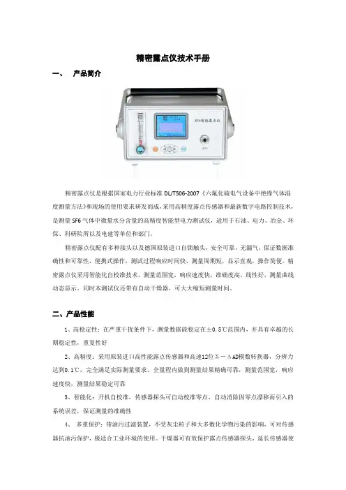
精密露点仪技术手册一、产品简介精密露点仪是根据国家电力行业标准DL/T506-2007《六氟化硫电气设备中绝缘气体湿度测量方法》和现场的使用要求研发而成,采用高精度露点传感器和最新数字电路控制技术,是测量SF6气体中微量水分含量的高精度智能型电力测试仪,适用于石油、电力、冶金、环保、科研院所以及电建等单位和部门。
精密露点仪配有多种接头以及德国原装进口自锁触头,安全可靠,无漏气,保证数据准确性和可靠性,便携式操作,测试过程响应时间快、测量周期短,显示直观,操作简便。
精密露点仪采用智能化自校准技术,测量范围宽,响应速度快,准确度高,线性好,测量曲线动态显示。
同时本测试仪还带有自动干燥器,可大大缩短测量时间。
二、产品性能1、高稳定性:在严重干扰条件下,测量数据能稳定在±0.5℃范围内,并具有卓越的长期稳定性,重复性好2、高精度:采用原装进口高性能露点传感器和高速12位Σ-ΔAD模数转换器,分辨力达到0.1℃,完全满足实际测量要求。
全量程内做到测量结果精确可靠,测量范围宽,响应速度快,测量结果稳定可靠3、智能化:开机自校准,传感器探头可自动校准零点,自动消除因零点漂移而引入的系统误差,保证测量的准确性4、多重保护:带油污过滤装置,不受灰尘粒子和大多数化学物污染的影响,可对传感器抗油污保护,极适合工业环境的使用。
干燥器可有效保护露点传感器探头,延长传感器使用寿命5、快速省气:开机进入测量状态后,露点值测定时间为3~5min。
该SF6微水测量仪|微水仪第一次需干燥管道和传感器,时间略长6、功能强大:4.7寸真彩触摸式液晶显示器,全中文操作界面。
直接显示露点值(℃)、微水值(uL/L)、日期及时间,动态显示露点测量曲线。
实时保存测量数据,最多可存储100组测量数据7、通信功能:具有RS232接口可与PC机串口相连,方便PC机对数据作进一步处理8、使用方便:采用日本原装进口自锁接头,插拔方便,安全可靠,无漏气。
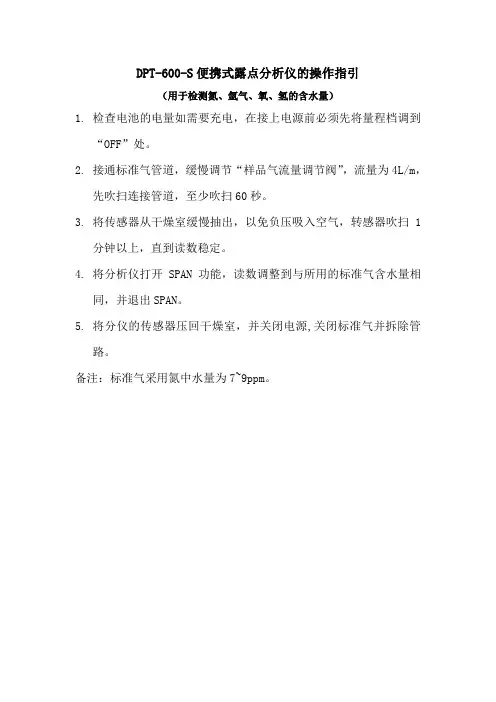
DPT-600-S便携式露点分析仪的操作指引
(用于检测氮、氩气、氧、氢的含水量)
1.检查电池的电量如需要充电,在接上电源前必须先将量程档调到
“OFF”处。
2.接通标准气管道,缓慢调节“样品气流量调节阀”,流量为4L/m,
先吹扫连接管道,至少吹扫60秒。
3.将传感器从干燥室缓慢抽出,以免负压吸入空气,转感器吹扫1
分钟以上,直到读数稳定。
4.将分析仪打开SPAN功能,读数调整到与所用的标准气含水量相
同,并退出SPAN。
5.将分仪的传感器压回干燥室,并关闭电源,关闭标准气并拆除管
路。
备注:标准气采用氮中水量为7~9ppm。
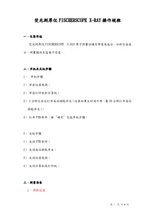
荧光测厚仪FISCHERSCOPE X-RAY操作规程一.仪器用途荧光测厚仪FISCHERSCOPE X-RAY用于测量涂镀层厚度及成分,分析合金成分,测量镀液主盐离子浓度。
二.开机及关机步骤1.开机步骤1)开启仪器电源;2)开启打印机和计算机;3)5分钟左右后打开高压钥匙开关(仪器如果长时间不用,要30分钟打开高压钥匙开关);4)打开FTM软件,按“确定”完成开机步骤。
2.关机步骤1)关闭FTM软件;2)关闭高压钥匙开关;3)关闭仪器电源;4)关闭计算机及打印机。
三.测量准备1.预热仪器为了保证测量的精确性和稳定性,仪器开启后必须进行充分的预热。
预热方法如下:完成正常的开机步骤后,点击图标进入“光谱”子程序。
按动图标开始不间断测量。
30分钟后按动图标停止测量,再按动图标退出“光谱”子程序后,即完成预热过程。
2.基准测量注意:这个步骤非常重要。
注意:在进行基准测量之前,必须先预热仪器。
因为仪器是以元素Ag为基准进行测量的,所以必须精确定位元素Ag的位置,不能偏移。
一般说来,一个星期做一次“基准测量”就可以了。
基准测量步骤如下:1)将元素Ag置于工作台上,调整其位置并聚焦清晰,使其清楚显示在视频窗口十字线中央。
2)选择菜单“一般—→测量基准”,按动“开始基准测量”按钮开始基准测量。
3)Ag测完之后,会提示放入原素Cu,(将元素Cu置于工作台上,使其显示在视频窗口十字线中央。
在按确定。
4)基准测量结束时,显示“基准测量完成,接受?”信息,按“确定”完成基准测量。
(如果显示“不需要做基准测量”信息,则按“确定”,再按“取消”退出即可。
)四.进行测量1.完成开机步骤,并进行预热及基准测量后,就可以开始测量样品了。
2.进行测量的步骤如下:1)根据待测样品的镀层情况,点击菜单“产品程式—→选择...或点击”选相应的产品程式。
2)将样品置于工作台上,调整其位置并聚焦清晰,使其清楚显示在视频窗口十字线中央。
3)按显示屏左下角的按钮“开始(s)”或仪器控制台上的“START”键开始测量,倒计时结束后即完成一次测量。
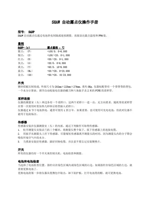
SHAW 自动露点仪操作手册型号: SADPSHAW自动露点仪通过电池供电间隔或连续测量,直接读出露点温度和PPM值。
量程SADP-(r)露点量程:℃紫点:(P)-100/0,0-6,000银点:(S)-100/-20,0-1,000红点:(R)-80/-20,0-1,000灰点:(G)-80/0,0-6,000黄点:(Y)-60/0,10-6,000蓝点:(BL)-80/+20,0-23,000金点:(GO)-50/+20,40/23,000外壳镀锌铝板压制而成,外部尺寸为202mm×225mm×276mm,重约5Kg。
仪器标配带有一个带背带的背包,一个水分计算表,调节自动校验电位器的螺刀和六角扳手及2米的PTFE的采样管。
采样连接仪器的测量室(头)两边各有一个采样口,这两个采样口一进一出,无方向要求。
随机带的采样管在第一次使用时需加热几秒钟后将管插入采样口。
仪器通过6节干电池供电,通常可使用1到2年。
如果需要,也可使用可充电电池,但此时仪器不能用于危险场合。
传感器传感器安装在仪器测量室(头)的内部,通过下列操作可取得传感器:1. 松开测量头安装法兰的三个螺丝,将测量头整个取下。
拔下传感器上的连接电缆。
2. 用扳手从测量头上拧下传感器。
尽量缩短传感器离开测量头的时间,因为测量头内的分子筛会吸收环境空气中的水分。
3.当重新安装好传感器,插好同轴电缆,并注意不要忘记安装铜垫片。
开关所有的仪器均有一个开关来控制关机、电池检查和测量。
电池和电池检查当选择了电池检查位置,指针应在绿色区域内或绿色区域的右边。
如果指针在绿色区域的左边,就需要更换电池了。
更换电池的第一步将仪器从便携包中取出,卸下防护板,打开电池筒的帽,就可更换电池。
危险场合使用—安全性所有Shaw 自动露点仪均取得EEx ia IIC T6的本安证书,将这点作为标准特性。
重点Shaw 传感器能够检测大多数气体,但有一些气体不太适合此传感器的结构,氨气和氯气应当避免接触传感器,HCL气体也能很快损坏传感器。
便携式露点仪安全操作及保养规程简介便携式露点仪也被称为便携式湿度计,是一种用于测量露点温度的设备。
它通常用于工业生产和实验室测试中,已成为一种必备仪器设备。
本文档旨在介绍便携式露点仪的安全操作和保养规程,以确保使用过程中的安全和可靠性。
安全操作规程1. 仪器安装在使用便携式露点仪之前,必须先正确安装仪器,包括连接电源和电缆。
使用便携式露点仪前需要确保以下几点:•仪器正常工作,没有任何损坏•所有电缆/接头的连接紧固牢固•电源线的插头处必须符合标准,保证接地正确2. 操作前检查在操作使用便携式露点仪之前,请做好以下检查工作:•确保正确安装仪器,并按照说明书准确操作仪器•确保所有显示屏幕的数据在合理范围内•确认电子地图正常工作•确认所有位置(如棱镜、接头和硬件) 没有出现损伤或明显改变3. 工作环境和条件使用便携式露点仪时,需要保持工作环境和条件良好。
因此,在使用时需要注意以下事项:•温度、湿度、气压和露点应该在正常范围内•意外事故和灾难风险应该减小到最低程度•工作时应该保证周围环境通风良好4. 用户制定计划在初次使用便携式露点仪之前,用户应该制定一个详细的计划,包括每天使用时间、环境、人员等,确保在使用过程中预防事故的发生。
5. 操作工作使用便携式露点仪时,请遵循以下指南:•验证所需数据,并确保仪器功能正常•如果需要移动设备,请注意不要过度拉动电线、插头等电缆和接头保养规程1. 周期性校准便携式露点仪应在使用前和使用过程中定期校准,以确保测量结果准确。
通常情况下,校准间隔时间应为1年。
在校准设备时,可以通过与其他设备进行比较来确定设备的准确性。
2. 保养计划用户应当控制便携式露点仪的环境,尤其是在高温、高湿度、高湿度和空气污染的环境更应加强关注。
在使用便携式露点仪时,请注意以下几个方面:•物体表面应保持干燥和清洁以减少灰尘和污垢的堆积•如果有污垢、油脂等附着于仪器表面,应使用清洁工具进行清洗•保证设备正常*工作温度3. 避免暴露在极端天气下便携式露点仪应避免暴露在极端天气下,因为露点仪在极端天气环境下容易受到损坏。
水露点分析仪操作指导书1 主要内容与适用范围本指导书规定了水露点分析仪的检查准备、操作程序和注意事项。
本指导书适用于XXX燃气有限公司SERIES100型水露点分析仪的使用作业。
2 检查与准备2.1 检查仪表应保持清洁,外表无损伤。
2.2 使用者要熟悉掌握仪表的使用规程及性能。
3 操作程序SERIES100型水露点分析仪主要由两部分组成。
一部分是现场采样分析系统,该系统是越靠近采样点越好,因此位于现场的分析仪小屋之内;另一部分是分析仪主机,位于控制室内的分析仪机柜里。
在两部分之间是通过信号电缆进行连接的。
3.1 采样系统的启动程序3.1.1检查采样和排放的阀门。
采样入口阀BV1和排放阀BV2关闭,采样出口阀BV3打开。
3.1.2 先打开采样入口阀BV1以使气体进入采样系统。
3.1.3 用调节阀调节样气的流量(是流量计的一部分),使流量值在流量计FM1上指示为3。
3.1.4 在显示单元看到稳定的测量值之前,让样气注入采样系统、管件和过滤器至少一个小时。
3.2 采样系统箱体内温度的调节3.2.1 打开分析仪的机箱,在机箱的左上角有一个方塑料盒。
3.2.2 去除盒上的铅封,打开上述的小盒,能看到一个温度刻度指示表盘及指针。
3.2.3 检查机盒内的当前指示是否为20℃左右,若偏差太大需检查是否温度调节器的功能正常。
3.2.4 用螺丝刀调节温度调节螺丝以达到预期的调节温度。
3.3 分析仪主机,在主机前面板的中央是水露点值的LCD显示区。
对当前的水露点值进行实时的显示,可以选择四种不同的单位进行显示;另外还可以进行标校的传感器型号选择以及报警信号的报警限值进行设定。
3.3.1 改变前面板上的显示单位3.3.1.1 前面板的是可以手动打开的。
用螺丝刀插入表板左下角的缺口,轻轻向上掀起前盖。
3.3.1.2 在显示区的左下角有一排共八个拨动开关,从左到右的六个开关是用来设置相应的显示单位的。
具体各开关的位置详见附表1。
HygroPalm 3手持式温湿度、露点仪表操作指南Copyright© 2004 目录0 概述 (1)1 系统组成 (1)1.1 手持式温湿度测量仪表表体HygroPalm 3 (1)1.2 温湿度传感器HygroClip系列 (2)1.2.1通用型温湿度传感器HygroClip S (2)1.2.2柔细温湿度传感器HygroClip SC05 (2)1.2.3高温管道温湿度传感器HygroClip HK25/40 (3)1.2.4精细插入式温湿度传感器HygroClip SP05 (3)1.2.5管状插入式温湿度传感器HygroClip HP28 (3)1.2.6剑状温湿度传感器HygroClip HS28 (4)1.2.7宽温温湿度传感器HygroClip IC-1 (4)1.3 转接延长线 (4)1.4 HW3软件及通讯线 (5)1.5 可选附件:电源适配器AC1207和支架PD1 (5)2 组装说明 (5)2.1 HygroClip S传感器的连接和拆卸 (6)2.2 HygroClip IC-1传感器的连接和拆卸 (6)2.3 金属连接件B5与表体第二通道的连接 (6)2.4 其余探头和转接线的连接 (6)2.5 通讯线的连接 (7)2.6 电池的安装与更换 (7)3 HygroPalm外形结构和功能说明 (7)3.1 按键功能说明 (7)3.2 开机/测量/锁定/关机 (7)3.3 LCD显示屏介绍 (8)4 菜单设置 (8)4.1 CALCULATE菜单 (8)4.1.1 湿度学参数介绍 (9)4.1.2 CALCULATE菜单操作 (9)4.2 DISPLAY菜单 (9)4.3 ADJUST M.PT菜单/ADJUST 1PT菜单/ADJUST REF菜单 (10)4.4 PROBE菜单 (10)4.5 SETTINGS菜单 (10)4.6 SYS-STATUS菜单 (10)5 校准 (10)5.1 校准方法 (10)5.1.1 ADJUST M.PT 多点校准 (10)5.1.2 ADJUST 1PT (单点迁移校准) (12)5.1.3 ADJUST REF使用参考探头作单点校准 (13)5.2 校准标准溶液 (14)5.3 校准步骤 (14)6 接口定义 (14)7 软件功能 (15)7.1 实时数据显示 (15)7.2 实时曲线/历史曲线描绘 (15)0 概述HygroPalm 3是常用的一款两通道手持温湿度、露点测量仪表,可以配接ROTRONIC 的多种数字化互换性温湿度探头,以适用各种不同场合的应用,广泛用于科研、卫生检疫、粮食仓储、环境实验、比对校准、造纸和纺织等生产过程。
便携式露点仪简易步骤
便携式露点仪简易步骤(MDM300)
1、简易步骤
1.1将待测气体阀门开大吹扫3分钟以上
1.2正确连接气路
1.3通过仪表的样气流量控制在0.2~1.2 标准升/分钟,建议
1.4用位于仪表顶部的电源开关开机。
1.5三分钟的初始化程序将自动运行,屏幕上显示倒计时间。
该过程中,传感器被加热,显著增强水分子的流动性从而加速和样气的平衡时间。
状态显示区域将显示内置传感器初始化中(Initializing internal sensor)。
1.6初始化程序完成后,仪表进入测量模式。
在开始的几分钟内,通常会看到显示的湿度值飞快下降,过冲后再回到最终的稳定数值上。
该响应是传感器初始化后的正常现象。
1.7仪表将显示测量值并给出直观指示,说明传感器开始对变化的湿度产生响应(状态栏为测量进行中(Measurement in progress) )以及一段时间后的最终测量读数(状态栏为测量完毕(Measurement OK))。
1.9当仪表的状态栏指示测量完毕(Measurement OK),其显示的读数就表示了样气中的真实湿气水平。
2、注意事项
2.1正确安装气路,防止漏气,影响结果。
2.2流量严格控制在0.2~1.2 标准升/分钟,防止损坏传感器。
2.3及时对仪器充电,否则电用完仪器会自动锁定。
2.5被测样气中不能含有油污或颗粒污染物。
2.6为了保证测量结果准确性,管路只能使用聚四氟乙烯或者不锈钢管和高质量的接头。
解密露点仪的原理露点仪如何操作露点仪原理露点仪是一种经典的测量方法。
让所测样气流经某一干燥剂,其所含水分**燥剂吸取,精准明确称取干燥剂吸取的水分含量,与样气体积之比即为样气的湿度。
该方法的优点是精度高,**允许误差可达0.1%;缺点是实在操作比较困难,尤其是必需得到充重量的吸取水质量(一般不小于0.6克),这对于低湿度气体尤其困难,必需加大样气流量,结果会导致测量时间和误差增大(测得的湿度不是瞬时值)。
因而该方法只适合于测量露点—32℃以上的气体,可以说市场上纯粹利用该方法测湿度的仪器较少。
在日常生活中我们可以看到,到夜间空气温度降低时,空气中的水分会有一部分析出,形成露水或霜。
这说明在水蒸气含量不变的情况下,由于温度的降低,能够使空气中原来未达饱和的水蒸气可变成饱和蒸气,多余的水分就会析出。
使水蒸气达到饱和时的温度就叫作“露点”。
测得露点温度,就可以从水蒸气的饱和含量表中查得其水蒸气含量。
由于温度降低过程中水蒸气含量并没有更改,因此,测定露点实际上就是测定了空气中的**湿度。
假如露点越低,表示空气中的水分含量越少。
露点可用专用的露点仪测定。
例如,空气经干燥器后的露点为—50℃,与—50℃对应的饱和水分含量为38.89mg/m3,说明空气中尚含有这些水分。
假如露点为—60℃,则饱和水分含量为10.68mg/m3、露点越低,说明干燥程度越高。
露点仪日常维护注意事项露点仪是能直接测出露点温度的仪器。
使一个镜面处在样品湿空气中降温,直到镜面上隐现露滴(或冰晶)的瞬间,测出镜面平均温度,即为露(霜)点温度。
使用时必需使吸入样本空气的管道保持清洁,否则管道内的杂质将吸取或放出水分造成测量误差。
那么,露点仪日常维护注意事项需要注意以下几点:1、测量仪应放置在安全位置,放止摔坏。
避开猛烈震动。
2、勿测有腐蚀性的气体。
3、探头使用确定时间应清洗并校验,校验期间隔为一年。
到需要校验时,与厂商联系。
4、调整气体流量时,掌控针型阀应渐渐打开,使流量指示在0.5—0.6升/分钟。
INSTRUCTION MANUAL FOR MODELS SADP, SADP-TR & SADP-DFor information about:See page:CALIBRATION 5AUTOMATICDEFINITIONS 10BASICBATTERIES 3CHECK 3BATTERYBATTERYREPLACEMENT 3CABINET 2CHECKING 5CALIBRATIONCERTIFICATION 19-22CASE 2CARRYINGCONTINUOUSREADINGS 2CONTROLS 3DESCRIPTION 2DESICCANT 7DRAWINGS 14-18INSTRUMENTS 2DUALRANGEELECTRICAL FUNCTION CHECK 8FLOWRATE 4GUARANTEE 3GASES TO AVOID 3AREAUSE 3HAZARDOUSHEAD SEAL KIT & SIEVE REPLACEMENT 7EQUIVALENTS 11HYGROMETRICOPERATION 4SUPPLY 2POWERPRESSURE 7PURGING 4BATTERIES 2RECHARGEABLETIME 7RESPONSESAFETY 3CONNECTIONS 2SAMPLEPIPE 2SAMPLESENSOR 3DESCRIPTION 6SENSOR:REMOVING 3SENSOR:CHECKS 2SPOTTEMPERATURE 6TESTPROCEDURE 4TROUBLESHOOTING 9-l0DIAGRAMS 14-18WIRINGCustomer OrderNumber Shaw/dealer Reference DateMODELS: SADP, SADP-TR & SADP-DThe SADP & SADP-TR are a battery operated portable unit designed for spot checks or continuous use, and gives direct indication in dewpoint temperature and parts per million on a 12cm analogue scale, SADP-D versions perform the same function but display only Dewpoint on a LCD display.The instrument may be used to give a continuous reading as long as sample gas is flowing through the test chamber [head] of the instrument, a reading will be given of the gas moisture content. Alternatively results are obtained in a few minutes when making spot checks.RANGESSADP-{r}: Purple: {P} Silver: {S}* Red: {R}Range:-100 / 0 deg.C DP, 0-6000 PPM.-100 / -20 deg.C DP, 0-1000 PPM, and 0-10 on TR version. -80 / -20 deg.C DP, 0-1000 PPM, 0-10 on TR version.Grey : {GY} Yellow: {Y}* -80 / 0 deg.C DP, 0 - 6000 PPM, and 0-10 on TR version. -60 / 0 deg.C DP, 10 - 6000 PPM.Blue: {BL}* *-80 / +20 deg.C DP, 0 - 23,000 PPM, (manual-cal). Special order ranges.CABINETAluminium and zinc-plated steel, stove enamelled. 202mm wide x 225mm deep x 276mm high [320mm high with test chamber (head) in the open position]. Typical weight 5kgs. Four feet fitted for bench use.The instrument is provided as standard with a padded carrying case with shoulder strap, a moisture calculator, a screwdriver for the Automatic Calibration control, a special key for the security plate covering the battery carriers, and a 2 metre length of special spiral-cut flexible PTFE (Teflon) sample pipe.SAMPLE CONNECTIONSThere is a push-on sample connection on each side of the test chamber [head] of the instrument. These connections are reversible and flow direction is not important.The fittings are designed for pipe having an internal bore of approximately 6mm [1/4’’]. Only the PTFE (Teflon) pipe provided should be used as other materials are unsuitable. The sample pipe should be heated for a few seconds before being pushed onto the instrument connection for the first time. This will provide a gas-tight connection and ensure accurate results.POWER SUPPLYThe instrument is supplied with 6 C-size R14 cells. In normal use these will last for one to two years.Rechargeable batteries may be used, if required, as long as the instrument is not to be used in a hazardous area [from the point of view of fire or explosion risk]. The use of re-chargeable batteries invalidates the certification of the equipment for use in hazardous areas.SENSORThe sensor is mounted inside the test chamber [head] of the instrument, and is accessible by removing the test chamber from the instrument as follows:1. Undo the three screws in the base flange of the head assembly and lift the complete headoff the instrument. Pull out the plug from the sensor.2. Using a 22mm AF spanner, unscrew the sensor from the head assembly. Do not leave thehead without a sensor fitted for more than a few minutes, as the desiccant will absorb moisture from the room air.3. When refitting the sensor, push the coaxial plug in firmly and don’t forget to fit the brassspacer.CONTROLSSADP instruments have a single rotary switch to the right of the indicator, which controls the power supply, the battery check and the range selection (in dual range models) . The switch positions are marked on the instrument fascia. SADP-D models have a single on/off switch BATTERIES AND BATTERY CHECKOn SADP models when the battery check position is selected the reading should be in the green sector, or to the right of it. If the reading is to the left of the green sector, then the batteries should be replaced. SADP-D models have a battery symbol in the display which comes on when the batteries require replacing.To replace the batteries, first remove the instrument from its carrying case. The battery holders will be found on the instrument back panel, and protected by a metal plate which has details of the safety certification marked on it. Remove the plate by undoing the 2 special screws with the key provided, take off the cap of each battery carrier, and replace the batteries with 6 VARTA Baby R14P cells. Always replace all 6 batteries at the same time, and do not leave completely discharged batteries in the instrument. Do not mix batteries and always replace them in a non hazardous location.HAZARDOUS AREA USE - SAFETYAll SADP Shaw Automatic Dewpoint meters are certified Intrinsically Safe as a standard feature. They must be fully assembled to meet the certification requirements, i.e. they must not be switched on in a hazardous location if any component is missing or removed. E.G. battery cover plate or sensor head assembly etc.The USA certification is to CLASS I, ZONE 0 AEx ia IIB+H2 T6, which effectively means that the instruments may be used in any environment except a coal mine.The ATEX certification is Ex II 1 G EEx ia IIC T6.This meansEx-European certification mark for electrical equipment for use explosive atmospheresII -Areas classified hazardous due to presence of flammable gases or vapour1 -Areas classified as Category 1 Risk according to the ATEX Directive (equates to Zone 0)G -Risk due to presence of flammable gases or vapours according to the ATEX Directive EEx ia - intrinsic safety level of protection ia according to EN 50202:2002IIC - suitable for use with all classes of gasses and vapoursT6 - the product has a maximum surface temperature of 85°C (in an ambient temperaturerange of -20°C to + 40°C) and can be used with any gases or vapours which have anignition temperature above this.July 2004OPERATIONBrief operating instructions will be found on the label fastened to the top of the instrument cabinet. The standard test procedure is as follows:1. Switch the instrument on, and check the battery condition.2. At the sample point to be tested open the sample valve or regulator slightly and checkthat no dirt or condensate is expelled. [If any dirt or condensate is present, wait until it is cleared, or abandon the test].The pressure of the sample source is not important: however the instrument needs a small sample of the air or gas which has been reduced to atmospheric pressure at the sample point (It must not exceed 2Bar for safe operation) - easily achieved by opening the valve just enough to allow a small flow to escape through the dewpoint meter.3. Connect the PTFE sample pipe supplied with the instrument between the sample tappingpoint and the instrument, using either of the connections of the head/sensor assembly.4. Adjust the sample valve or regulator to give a gentle flow through the instrument, [5/10L/min. is ideal — but the flow rate is not particularly critical. Do not exceed a flow of about 20 L/min].5. Allow the sample to flow for 2 or 3 minutes in order to purge the sample pipe (a longertime might be needed if testing very dry gas - drier than about -65 c. dewpoint). Then place a finger over the outlet connection of the instrument head, and the sample pressure will cause the head to open. Remove finger from the instrument when the head is fully open. [If there is insufficient sample pressure, fit a length of 1 or 2 metres of flexible pipe to the outlet connection of the instrument head, and slowly raise the head by hand].6. The instrument reading will move up the scale (wetter), and stabilise. When there is nofurther change in reading, note the result. If the reading moves up the scale (wetter) and then moves down the scale (drier) then either the sample pipe was not purged enough before the head was raised, or the sample is becoming drier during the test. (Perhaps by taking the sample from a pipe in which the gas has been stagnant for some time).If in doubt about the suitability of the sample flow rate, or the materials of the sample pipe being used, increase the sample flow rate after the final reading has been obtained.If the instrument moves to a drier reading this indicates that the original flow rate was too low, or that there is a leak in the system allowing ambient moisture into the sample, or that the sample pipe itself is still wet.7. After the test is complete, and if continuous reading is not needed, close the instrumenthead ready for the next test.8. Note these instruments are designed for rapid moisture determination when operatedfrom Dry to Wet, in this case they should give a 95% step change within 30 seconds.When operated Wet to Dry we cannot quote any response time as this is dependant upon many variables but will be considerably longer than the Dry to Wet response time.CALIBRATION CHECKINGWhen Shaw invented the capacitance sensor many years ago it was a real breakthrough. The second major breakthrough came when we introduced the unique Automatic Calibration System for our sensors.This is a major advantage of the Shaw measurement system. No other instrument can he checked so easily and quickly.The system relies on the fact that each sensor is designed to give no further increase in reading when it reaches its maximum moisture level. This means, for example, that the Yellow Spot sensor used in the Model SADP-Y for the range -60 to 0 C dewpoint will read 0 deg C when exposed to gas at 0 deg C dewpoint, but will continue to read 0 deg C dewpoint when it is exposed to wetter gas. The system can therefore be calibrated very simply by exposing the sensor to anything wetter than 0 deg C dewpoint, and adjusting the reading to that point on the dial. In practice there is not an immediate cut-off, and the 0 deg C dewpoint mark on the dial will be found at about 3 deg below the Automatic Calibration line. This enables the instrument to retain the maximum possible accuracy throughout its range.In practice, the instrument’s calibration is checked as follows:AUTOMATIC CALIBRATION All Models excluding SADP-Bl1. Ensure that no gas sample is connected to the instrument head connections. Switchmeter to Read, or Standard range if a TR Model. Switch to On for SADP-D models.2. Raise the head of the instrument by hand and pump it up and down a few times, endingin the raised position.3. After about 1 minute (not critical, but not more than a few minutes) check theinstrument reading. On SADP models it should be at the Automatic Calibration line. It is not critical within 1 or 2 degrees. N.B. Extremes of humid or dry room air conditions may affect the reading slightly - see below. SADP-D models must be set to the Wet limit of the sensor, see table of P2 for details.4. If the reading requires adjustment locate the Automatic Calibration control, which is tobe found on the front panel of the instrument, and using the small screwdriver provided, turn the control clockwise to increase the reading (wetter) or anti-clockwise to decrease it.5.Close the instrument head.NOTE: When the outside temperature is below 0 deg C or in an Air-Conditioned environment the room dewpoint may also be below 0. Under these conditions we suggest that an independent check of the room dewpoint be made against which the calibration can be set or, more easily, assume that the room dewpoint temperature is the same as the outdoor air temperature. This will be quite sufficient except in very unusual weather conditions. MANUAL CALIBRATION For Models SADP-Bl and SADP-D-BlThe wide range of the Model SADP-Bl and SADP-D-Bl means that very rarely will the room air dewpoint be above the maximum of the range. This means that true Automatic Calibration will not work. To overcome this, simply use a wet & dry bulb hygrometer, or similar, to determine the room air dewpoint temperature, and at stage (4) above set the reading to the actual air dewpoint. There is, of course, no Automatic Calibration line on these meters.We suggest you check the automatic calibration a minimum of two to three times each year, and that annually the instrument is returned for a full range calibration checkTHE SENSORThe Shaw High Capacitance Sensor has been undergoing continuous development since it was invented by Mr. J. L. Shaw in the late 1940’s. Protected by world patents the sensor is manufactured by a unique automated process, which results in a long life device with fast response, high accuracy and good stability.Construction of the sensor starts with an ultra-high purity aluminium wire, which is coated with a hygroscopic layer and finally covered by a film of porous gold. The gold film and the aluminium core form the plates of the capacitor. The capacitance value, and the change in capacitance over the measuring range of each sensor is many times greater than any other device, resulting in a system which can operate at low frequency [50 or 60Hz] without any risk of interference or pick-up from external cables or other sources.Some of the water vapour molecules in the atmosphere surrounding the sensor will enter the dielectric layer where, due to the extremely small size of the pores, their Brownian motion will be limited, their energy will consequently be reduced and they will condense into liquid water. Due to the very high dielectric constant of water [about 80] compared with the other vapours which may be present, this produces a marked change in the dielectric value of the sensor which is then measured by the analyser. A dynamic equilibrium will exist between the water vapour outside the sensor and the condensed water within the pores. This equilibrium is maintained, and the response time of the sensor can generally be considered to be at least as quick as the system into which it is installed.Molecules larger than water vapour [one of the smallest gas molecules] cannot enter the pores, making the sensor resistant to many contaminants and specific to water vapour pressure regardless of the carrier gas. Even molecules such as Hydrogen which may enter the pores, have such a low dielctric constant, and will not condense, and so cannot interfere with the reading.This is a feature unique to the Shaw sensor. All other sensors of the capacitance type are affected by molecules such methanol which cause great inaccuracy.TEMPERATUREShaw sensors are designed to work at room temperature. Typical ambient variations experienced throughout the world are quite acceptable, but avoid placing the instrument in direct sunlight or near a source of radiant or convected heat. In countries, which experience extremes of temperature, always carry out the Automatic Calibration with the instrument at its operating temperature.For special applications where high or low temperature operation seems unavoidable please refer to your local Shaw dealer or us.PRESSUREThe Shaw sensor is a water vapour pressure detector. The Automatic Dewpoint Meter operates with the sensor at atmospheric pressure, and the readings given in dewpoint temperature and parts per million are therefore correct at 1 bar [A]. However, dewpoint temperature is directly proportional to pressure, and the results obtained from the instrument can be referred to any other pressure by use of the Shaw pressure calculator, which is supplied with the instrument. Instructions for the use of the calculator are printed on it.RESPONSE TIMEThe response time of any water vapour pressure detector will naturally be very much quicker from dry to wet, than from wet to dry. This is the reason that the Shaw Automatic Dewpoint Meter is so successful: the sensor is kept in a dry condition when it is not in use, and therefore results are obtained in the quickest possible time.To check whether a particular instrument is within specification, carry out the Calibration procedure, close the instrument head and note the reading 10 minutes later. It should be drier than mid range. If the reading is wetter than this after the 10 minute period then either the sieve in the head/sensor assembly is wet, or there is some other problem and the complete instrument, should be returned to our works for examination.DESICCANT & HEAD SEAL KIT REPLACEMENTThe sensor is kept dry when not in use by the desiccant contained in the head assembly. In the Model SADP this is designed to maintain the sensor at about -75 C dewpoint, many years’ experience has shown that this maintains the optimum responsiveness of the sensor.The above readings should be obtained when the instrument has been left with the head in the closed position for a few hours - e.g. overnight. As the desiccant only has to dry a very small volume of air or gas after each test, and is completely isolated from the test gas and the room air, it has a life of approximately 5 years in normal use. After very long service, or in case of accident the desiccant can easily be replaced as follows:1. Grasp the black plastic ring (Head Seal), which separates the inner and outer sectionsof the head assembly, and unscrew it until it can be removed. Pull the inner section out of the outer section. In the case the Head Seal requires Replacement slide the old seal off noting the orientation and place the replacement on a firm bench upside down (threads uppermost. Now insert the head into the seal, and when it meets the seal push firmly till it passes the seal.2. Unscrew the plain brass base of the inner section, discard the old desiccant and replacewith new.3. Check that the white seal is intact and in place in the base of the inner section and thenre-assemble the head assembly. Otherwise replace the white grommet seal if necessary, applying a trace or silicon grease and ensuring the seal is in place correctly and the sensor will travel up and down it without displacement or contamination with silicon grease of the sensor filtersELECTRICAL FUNCTION CHECKIf there is any doubt about the functioning of the Analyser, the following tests may be carried out.1. Switch the instrument off.2. Check that meter reading is accurately at the zero [left-hand] end of the scale. If not,adjust the reading by means of the plastic screw on the meter face.3. Remove the instrument head by taking out the 3-screws in the base flange, anddisconnect the sensor by pulling out the coaxial plug.4. Switch instrument to the Battery Check position to confirm that the batteries are in goodcondition (replace them if they are not), and then select the read position (STD range on dual range models).5. Apply a short circuit to the sensor cable plug on the instrument - the voltage is extremelylow and so there is no hazard.6. Adjust the Automatic Calibration control to give a reading of full scale. (i.e. on theAutomatic Calibration line.)7. Remove the short circuit and the reading should return to the left-hand end of the scale.If adjustment is necessary, remove the cabinet cover, after removing the screws oneither side and pulling it upwards, and locate the control marked VP3 on the printedcircuit board.This establishes that there is no major fault in the instrument. If the tests so far do not produce the expected results, the instrument should be returned to our Bradford works, or your local dealer.8. Apply a load of 8.6k Ohms to the sensor cable plug. Re-adjust the reading to full scale,using the Automatic Calibration Control.9. Increase the load to 18.6K Ohms. The reading should decrease to 62% of scale + 1%.10. Increase the load to 62K Ohms. The reading should decrease to 21.5% of scale with thesame tolerance as above.11.Re-fit the head assembly, and carry out the Automatic Calibration procedure.Note removal of the lid or adjustment of any internal control may invalidate guarantee THIS COMPLETES THE ELECTRICAL FUNCTION CHECK.N.B. Please note that VP1 on the printed circuit board is factory set. If the adjustment of this control is altered, it will be necessary to return the instrument to our works.GUARANTEEAll Shaw products are guaranteed conditionally for a period of two years from purchase, exceptions being accidental damage, or damage caused by misuse or abuse. This period may be reduced to one year if the instrument is purchased from the stock of one of our overseas dealers. A Guarantee certificate is available by request.July 2004IMPORTANTShaw sensors are suitable for many different industrial research applications Most gases can be checked for their moisture content, and there is no need for the calibration to be altered when changing between different gases - even such different gases as Carbon Dioxide and Hydrogen: the sensor operates only with reference to the water vapour content. However there are some gases which must be avoided as they are not compatible with the materials of construction of the sensor. Ammonia and Chlorine must be avoided at all times, even in small quantities. HCL also attacks the sensors very quickly. Gases such as Sulphur Dioxide (S02) can be monitored as long as the moisture content is low - generally less than 100VPM. If in doubt, please check with us first.TROUBLE SHOOTINGSYMPTOM: WET READING REMEDYCAUSE: Static on Indicator Moisten indicator faces with a 50/50 mixture ofdetergent and water, or use proprietary anti-static cleaner.INDICATORPOLISHFACE.DONOTSYMPTOM:FULL SCALE READING REMEDYCAUSE: Wet sample gas. Stop gas supply, switch meter off and close HeadCAUSE: Short circuit of coaxial cable Remove instruments Head by undoing 3 screwsin base flange and disconnect plug from sensor.If meter still reads over Full Scale, cure the shortcircuit in the cable or plugs. (Or replace cable)CAUSE: Short circuit in Sensor. With Head in closed position apply 20 to 50VD.C. VERY briefly (less than 0.1 second) to the T his must not be performed on any sensor connections (coaxial socket). Polarity not Sensor within its guarantee period important. When short circuit cured, check Without our written authorisation.Automatic Calibration. If unsuccessful, returnHead/Sensor assembly to us or your local dealer. SYMPTOM: ZERO READING REMEDYCAUSE: Co-ax lead disconnected Remove instrument head and reconnect co-axcable to sensor.CAUSE: Open circuit on sensor. Disconnect plug from sensor and connect centrepin of plug to outer connection (i.e. short-circuitthe cable). Reading of more than maximum willbe obtained. Check sensor connection or replacesensorJuly 2004SYMPTOM: WET READING REMEDYCAUSE: Leak in system or use of Cure the leak. Replace unsuitable pipe with unsuitable sample pipe. copper or stainless steel. Flexible connectionsshould be made with PTFE pipe supplied.NEVER use rubber or plastic pipe. SYMPTOM: WET READING REMEDYCAUSE: Comparison of readings with This type of indicator reads about 10 manual cooled-mirror deg. too dry at about -50 deg dewpointdevice. due to temperature gradients within thedevice. The error increases at drierlevels.SYMPTOM: SLOW RESPONSE REMEDYCAUSES: Water vapour in system. Sample flow rate of 5/10 L/min. isFlow rate too low. optimum. Do not exceed 20L/min.Sample pipe too large. Check if there is any possibility ofUnsuitable sample pipe. sensor being contaminated with oil ordeposits.dirtSYMPTOM: DRY READING REMEDYCAUSE: Damaged or faulty sensor Check Automatic Calibration, or returnsensor for full calibration check by us.BASIC DEFINITIONSWATER VAPOUR PRESSURE: is the pressure exerted by the water vapour contained in any mixture of gases. The total pressure exerted by the gas mixture is the sum of the pressures exerted by its components — including the water vapour. Water Vapour Pressure varies in direct proportion to the total gas pressure.DEWPOINT TEMPERATURE: is defined as the temperature to which the gas must be cooled in order that it should be saturated with water vapour (i.e.: 100% relative humidity.) For practical reasons it is referred to water above 0 deg C and ice below 0 deq C.PARTS PER MILLION BY VOLUME: PPM(v) or VPM is the ratio of the water vapourPARTS PER MILLION BY WEIGHT: PPM(w) is the same as VPM, except that the figure is modified according to the ratio of the molecular weight of water vapour to the molecular weight of the carrier gas mixture.RELATIVE HUMIDITY: is the ratio of the actual water vapour pressure in the gas to the saturation water vapour pressure at the same temperature.July 2004SADP & SADP-D SpecificationAccuracy: +/-1PPM , (+/-3 deg.C DP Red Spot, +/-4 deg.C DP, all others).Type: Portable hygrometer in stove enamelled zinc plated steel and alloy case,complete with padded carrying case. For table top or portable use withdessicant chamber for rapid readings. Certified intrinsically safe foroperation in hazardous areas to Class I, Zone 0 Aex.ia IIB +H2 T6. Dimensions / Weight: Overall dimensions: 202mm x 225mm x 276mm High (320mm with headextended) Weight: 4 Kg approx.Display: SADP 12cm Taut Band indicating meter showing Dewpoint and ppm, withamplified range of 0-10ppm on TR versions.SADP-D 2cm 3 1/2 Digit LCD wit battery check symbol.Sensor Connection: Internal.Power Supply: 9V DC ( 6 x VARTA Baby R14P cells ) InternalSampling: Pressure: atmospheric with flow rate of 5 - 10 litres/minuteOutputs: None.Calibration: Autocal on all but Blue range.Accessories / Options: SU4 Lo, Med or Hi Sample system for sample conditioning pressurisedgases to atmospheric conditions and controlled flow.Sensor Type {r}: Purple: {P} Red: {R}Sensor Range:-100 / 0 deg.C DP, 0-6000ppm, (auto-cal)-80 / -20 deg.C DP, 0-1000ppm, and 0-10 on TR version, (auto-cal)Grey : {G}-80 / 0 deg.C DP, 0 - 6000 ppm, and 0-10 on TR version, (auto-cal) Blue : {Bl}-80 / +20 deg.C DP, 0 - 23,000 ppm (manual-cal)To Order:Analogue versions SADP {r}: suffix TR if required for G and R rangesonly.Digital Versions SADP-D-{r}。
操作手册XDT系列在线露点仪约克仪器公司目录1.0 综述 (1)2.传感器和采样技术 (3)2.1 传感器使用注意事项 (3)2.2 传感器技术指标 (4)2.3 传感器安装和采样技术 (4)2.3.1 直接安装 (5)2.3.2 采样安装 (6)2.4 机械安装 (7)2.5 故障查找 (8)3.仪器 (9)3.1 变送器使用注意事项 (9)3.1.1 电磁兼容性 (9)3.2 仪器技术指标 (10)3.3 安装 (11)3.3.1 仪器机械安装 (11)3.3.1.1 DT-PM (DIN43700) 安装 (11)3.3.1.2 DT-NEMA (IP65) 安装 .............................................................................................1 1 3.3.2 电气连接 .. (12)3.3.2.1 连接电源 (12)3.3.2.1.1 交流电源连接 (13)3.3.2.1.2 低压直流电源选项- 电气连接 (13)3.3.2.2 传感器连接 (13)3.3.2.3 报警继电器接线 (13)3.3.2.4 模拟输出 (14)3.3.2.5 RS-232 输出选项 (15)3.4 操作 (15)3.4.1 启动 (15)3.4.2 显示 (16)3.4.3 按键 (16)3.4.4 操作说明 (17)3.4.4.1 查看露点模式 (17)3.4.4.2 报警 (19)3.4.4.3 启动校验 (20)3.4.4.3.1 SpanCheck™模式 (21)3.4.4.3.2 单点自校验, 手动或定期 (22)3.4.4.4 查看系列号模式 (25)3.4.5 设定说明 (25)3.5 可设定声光报警选项 (28)3.6 仪器故障查找 (29)3.7 维护 (31)词典 (33)附录 A: 操作状态的流程图 (37)附录B: 设定状态的流程图 (39)附录C: 传感器机械尺寸 (40)附录D: 可选传感器接头 (41)附录E: DT 电路板尺寸 (42)附录F: 传感器/SpanCheck™操作原理 (45)附录G: 露点响应时间分析 (46)附录H: 样气过滤器需要考虑的事项 (48)附录I: DT 接地需要考虑的事项 (49)附录J: 模拟输出与露点的对应 (50)附录K: RS-232C 协议 (52)附录L: 更换传感器的步骤 (55)附录M: LBS & ppmV 计算中的不确定度 (56)索引 (57)部分 1: 导言1.0 XDT综述XDT 在线露点仪基于微处理器技术,能在-100°C~+20°C露点温度范围内测量气体中水分含量。