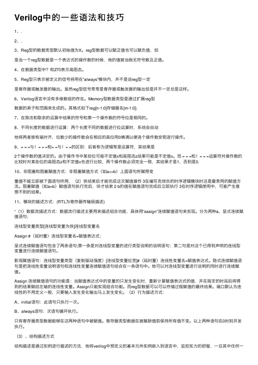
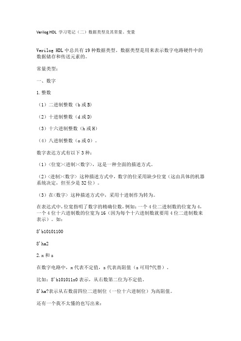
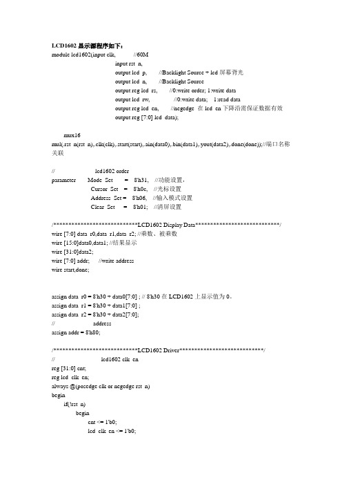
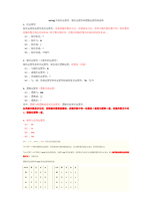
parameter size = 8,longsize = 16;
reg [size:1] opa,opb;
reg [longsize:1] result;
begin: mult
reg [longsize:1] shift_opa,shift_opb;
begin
repeat(2) //重复两次产生下面的data变化
begin
data=4'b0000;
`stim0001;
/***************************************************************
宏定义stim引用,等同于#100 data=4'b0001;。注意引用时要用 `符号。
clk=0;
#3 reset = 0;
#5 reset = 1;
end
always #5 clk = ~clk;
endmodule
2.Verilog HDL建模在TOP-DOWN设计中的作用和行为建模的可综合性问题
(1)累加器用寄存器(ACCUMULATOR RREGISTER)
2) UDP可以有多个输入端,最多允许有10个输入端。
3) UDP所有端口变量必须是标量,也就是必须是1位的。
4) 在UDP的真值表项中,只允许出现0、1、X三种逻辑值,高阻值状态Z是不允许出现的。
5) 只有输出端才可以被定义为寄存器类型变量。
6) initial语句用于为时序电路内部寄存器赋初值,只允许赋0、1、X三种逻辑值,缺省值为X。
primitive 元件名(输出端口名,输入端口名1,输入端口名2,…)
output 输出端口名;
input 输入端口名1, 输入端口名2,…;
reg 输出端口名;
initial begin
输出端口寄存器或时序逻辑内部寄存器赋初值(0,1,或 X);
end
table
4.2.1仅用于产生仿真测试信号的Verilog HDL行为描述建模
module gen_clk ( clk, reset);
output clk;
output reset;
reg clk, reset;
initial
begin
reset = 1; //initial state
shift_opa = opa;
shift_opb = opb;
reslut = 0;
repeat(size)
begin
if(shift_opb[1])
result = result + shift_opa;
shift_opa = shift_opa << 1;
wire [3:0] qout;
`define stim #100 data=4'b //宏定义stim,可使源程序简洁
event end_first_pass; //定义事件end_first_pass
hardreg reg_4bit (.d(data), .clk(clock), .clrb(clearb), .q(qout));
/*****************************************************
类似于C语言的 printf 语句,可打印不同时刻的信号值
******************************************************/
initial
/**********************************************************************************
把本模块中产生的测试信号data、clock、clearb输入实例reg_4bit以观察输出信号qout.实例
reg_4bit引用了hardreg
f2(d[1],clk,clrb,q[1],),
f3(d[2],clk,clrb,q[2],),
f4(d[3],clk,clrb,q[3],);
endmodule
//在这使用了以上模块
module hardreg_top;
reg clock, clearb;
reg [3:0] data;
always @(negedge clock)
begin
case(opcode)
3'b000: #`ALUdly alu_out=accum; //Pass Accumulator
3'b001: #`ALUdly alu_out=accum; //Pass Accumulator
DFF d2(r[2],,load,data[2],rst);
DFF d1(r[1],,load,data[1],rst);
DFF d0(r[0],,load,data[0],rst);
Endmodule
其中 DFF和and都是Verilog语言中保留的关键字分别表示带复位端的D触发器和与门。
#200 -> end_first_pass;
/***********************************************
延迟200个单位时间,触发事件end_first_pass
************************************************/
end
//一个计数器
always @(a or b or c)
//D触发器
module flop(data,clock,clear,q,qb);
input data,clock,clear;
output q,qb;
nand #10 nd1(a,data,clock,clear),
//输入1 输入2 输入3 …: 输出
逻辑值 逻辑值 逻辑值 …: 逻辑值 ;
逻辑值 逻辑值 逻辑值 …: 逻辑值 ;
逻辑值 逻辑值 逻辑值 …: 逻辑值 ;
… … … …: …;
endtable
endprimitive
注意
1) UDP只能有一个输出端,而且必定是端口说明列表的第一项。
3'b110: #`ALUdly alu_out=accum; //Pass Accumulator
3'b111: #`ALUdly alu_out=accum; //Pass Accumulator
default: begin
$display("Unknown OPcode");
always @(end_first_pass)
clearb = ~rb;
always @(posedge clock)
$display("at time %0d clearb= %b data= %d qout= %d", $time, clearb, data, qout);
(2)RISC算术运算单元(RISC_ALU)
`timescale1ns/100ps
module riscalu ( alu_out, zero, opcode, data, accum, clock );
output [7:0] alu_out;
reg[7:0] alu_out;
DFF d7(r[7],,load,data[7],rst);
DFF d6(r[6],,load,data[6],rst);
DFF d5(r[5],,load,data[5],rst);
DFF d4(r[4],,load,data[4],rst);
DFF d3(r[3],,load,data[3],rst);
iv2(nclock,clock);
endmodule
//在此处使用了以上定义的D触发器
module hardreg(d,clk,clrb,q);
input clk,clrb;
input[3:0] d;
output[3:0] q;
flop f1(d[0],clk,clrb,q[0],),
**********************************************************************************/
initial
begin
clock = 0;
clearb = 1;
end
always #50 clock = ~clock;
$finish; //结束仿真
end
endmodule
//加法器
module adder(sum, cin, count, a, b);
input [2:0] a,b;
output [3:0] sum;
output [3:0] count;
assign {count,sum} = a + b + cin;
endmodule
//三态门
module san_state_gate(out, in, en);
input en,in_a;
output out;
bufif1 mybuf(out, in, en);
endmodule
//user defined primitives
UDP语言格式
shift_opb = shift_opb >> 1;
