翻译振动台说明书
- 格式:doc
- 大小:45.00 KB
- 文档页数:5
longdate振动台ld-75tp说明书一、产品简介LD-75TP振动台是一款高性能的振动测试设备,由Longdate公司研发和生产。
该振动台主要用于模拟各种振动环境,为产品测试、试验和研究提供可靠的振动环境。
振动台可根据用户需求进行定制,满足不同场合的使用需求。
二、产品特点1.高精度:LD-75TP振动台采用先进的控制系统,实现高精度的振动控制。
2.稳定可靠:振动台主体采用高强度金属材料,具有良好的抗振性能和稳定性。
3.多种振动模式:支持正弦波、随机波、冲击波等多种振动模式,满足不同测试需求。
4.易于操作:控制系统采用人性化设计,操作简便,便于上手。
三、应用领域LD-75TP振动台广泛应用于汽车、航空航天、电子、家电等行业,为产品测试、试验和研究提供可靠的振动环境。
四、操作指南1.开机:打开电源开关,启动振动台。
2.设置振动参数:根据需求设置振动模式、频率、幅度等参数。
3.启动振动:在控制系统上启动振动,观察振动台运行情况。
4.停止振动:完成测试后,关闭振动台电源。
五、维护与保养1.定期检查振动台的运行状态,发现异常及时处理。
2.保持振动台清洁,避免灰尘和污物影响设备性能。
3.定期给振动台传动部位润滑,保证运行顺畅。
4.不要在振动台上放置重物,以免影响振动性能。
六、安全注意事项1.操作前,请仔细阅读说明书,了解振动台的使用方法。
2.操作过程中,切勿将身体部位伸入振动台工作区域,以免发生危险。
3.勿让儿童和未经许可的人员操作振动台。
4.振动台运行时,请勿触摸振动台表面,以免受伤。
请遵循以上注意事项,确保振动台安全、可靠地运行。
爱固仪器 爱固仪器模拟运输振动试验台☆ 使 用 说 明 书 ☆东莞市爱固检测仪器有限公司--------------------------------------------------------------------------------------------------------------------------------------------------------------------------------------------------------------------------------------------------------------------------------------前言感謝貴司選擇了本公司的產品,本公司不僅給貴司提供質量優良的產品,而且將提供可 靠的售後服務。
為確保使用人員之人身安全及儀器的完好性,在使用本儀器前請充分閱覽此操作手冊, 確實留意其使用上的注意事項。
本操作手冊詳細介紹此儀器之設計原理、依據標準、構造、 操作規範、注意事项、品质保证等內容。
在本操作手冊中如有提及之各種 “試驗規定”、 “標準”時均只作參考用,如貴司覺得有異議請自行檢閱相關標準或資料。
特別聲明: 特別聲明:本操作手冊不能作為向本公司提出任何要求的依據。
本操作手冊的解釋權在本公司。
--------------------------------------------------------------------------------------------------------------------------------------------------------------------------------------------------------------------------------------------------------------------------------------目錄目 錄 - - - - - - - - - -- - - - - - - - - - - - - -- - - - - - - - - - - - - -- - - - - - - - - - 1 安 全 上 的 注 意 - -- - - - - - - - - - - - - -- - - - - - - - - - - - - -- - - - - - - - - - 2 壹 ﹑ 概 論 - - - - - -- - - - - - - - - - - - - -- - - - - - - - - - - - - -- - - - - - - - - - 3 貳 ﹑ 依 據 標 準 - -- - - - - - - - - - - - - -- - - - - - - - - - - - - -- - - - - - - - - - 3 參 ﹑ 儀 器 說 明 - -- - - - - - - - - - - - - -- - - - - - - - - - - - - -- - - - - - - - 3 - 4 一 ﹑ 儀 器 結 構 - -- - - - - - - - - - - - - -- - - - - - - - - - - - - -- - - - - - - - - - 4 二 ﹑ 儀 器 規 格 - -- - - - - - - - - - - - - - - - - - - - - - - - - - - -- - - - - - - - - - 4 肆 ﹑ 儀 器 安 裝 - -- - - - - - - - - - - - - -- - - - - - - - - - - - - -- - - - - - - - - - 5 伍 ﹑ 試 驗 步 驟 - -- - - - - - - - - - - - - -- - - - - - - - - - - - - -- - - - - - - - - - 5 陆 ﹑ 注 意 事 項 - -- - - - - - - - - - - - - -- - - - - - - - - - - - - -- - - - - - - - - - 5 柒 、 品 質 保 證 - -- - - - - - - - - - - - - -- - - - - - - - - - - - - -- - - - - - - - - - 6 捌 ﹑ 備 註 - - - - - -- - - - - - - - - - - - - -- - - - - - - - - - - - - -- - - - - - - - - - 7--------------------------------------------------------------------------------------------------------------------------------------------------------------------------------------------------------------------------------------------------------------------------------------安全上的注意1. 安全上的記號: 在本手冊中,關於安全上的注意事項以及使用儀器時有下列重要的各顯示事項,爲了防止 意外事故及危險,請務必遵守下列危險﹑警告﹑注意的記言:危險: 危險:此顯示的項目,表示爲如不遵照,操作者有可能受到傷害。
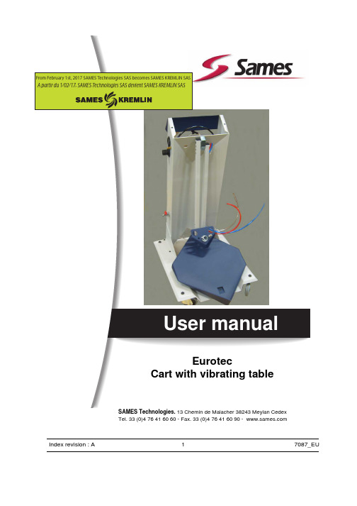
From February 1st, 2017 SAMES Technologies SAS becomes SAMES KREMLIN SASUser manualEurotecCart with vibrating tableSAMES Technologies. 13 Chemin de Malacher 38243 Meylan CedexTel. 33 (0)4 76 41 60 60 - Fax. 33 (0)4 76 41 60 90 - Index revision : A17087_EUAll communication or reproduction of this document, in any form whatsoever and all use or communication of its contents are forbidden without express written authorisation from SAMES Technologies.The descriptions and characteristics mentioned in this document are subject to change without prior notice.© SAMES Technologies 2010WARNING : SAS Sames Technologies is registered with the Ministry of Labour as a training institution.Throughout the year, our company offers training courses in the operation andmaintenance of your equipment.A catalogue is available on request. Choose from a wide range of courses toacquire the skills or knowledge that is required to match your productionrequirements and objectives.Our training courses can be delivered at your site or in the training centre at ourMeylan head office.Training department:Tel. 33 (0)4 76 41 60 04E-mail:**************************SAS Sames Technologies operating manuals are written in French and translated into English, German, Spanish, Italian and Portuguese.The French version is deemed the official text and Sames will not be liable for the translations into other languages.Index revision : A27087_EUEurotecCart with vibrating table1. Health and safety instructions- - - - - - - - - - - - - - - - - - - - - - - - - - - - - 42. Description- - - - - - - - - - - - - - - - - - - - - - - - - - - - - - - - - - - - - - - - - - 52.1. General presentation . . . . . . . . . . . . . . . . . . . . . . . . . . . . . . . . . 52.1.1. Vibrating table . . . . . . . . . . . . . . . . . . . . . . . . . . . . . . . . . . . . . . . 52.1.2. Support arm for powder pump. . . . . . . . . . . . . . . . . . . . . . . . . . . 52.1.3. Control panel . . . . . . . . . . . . . . . . . . . . . . . . . . . . . . . . . . . . . . . . 53. Characteristics - - - - - - - - - - - - - - - - - - - - - - - - - - - - - - - - - - - - - - - 63.1. General characteristics . . . . . . . . . . . . . . . . . . . . . . . . . . . . . . . 63.2. Pneumatic characteristics . . . . . . . . . . . . . . . . . . . . . . . . . . . . . 64. Operation- - - - - - - - - - - - - - - - - - - - - - - - - - - - - - - - - - - - - - - - - - - 65. Tools - - - - - - - - - - - - - - - - - - - - - - - - - - - - - - - - - - - - - - - - - - - - - - 66. Installation - - - - - - - - - - - - - - - - - - - - - - - - - - - - - - - - - - - - - - - - - - 76.1. Set up procedure . . . . . . . . . . . . . . . . . . . . . . . . . . . . . . . . . . . . 87. Troubleshootings - - - - - - - - - - - - - - - - - - - - - - - - - - - - - - - - - - - - - 88. Spare parts- - - - - - - - - - - - - - - - - - - - - - - - - - - - - - - - - - - - - - - - - - 9 Index revision : 31. Health and safety instructionsWARNING : This manual contains links to the following user manual•see RT Nr 7079_EU for MG 400-AG 400 spray guns and CGU 400 control module.Note: This device complies with the ATEX directive. It may be dangerous if it is not used in com-pliance with the safety regulations specified in this manual.WARNING : This cart is intended for use with powder-paint spraying apparatus only (MG 400 manual spray gun and AG 400 automatic spray gun).•This device must only be used by personnel trained and accredited by SAMES Technologies.Operating staff must first read the user manual and the user manuals for any peripheral electrical equipment present in the spraying area. The workshop manager must ensure this is the case.•The cart must always be installed and used in areas where there is no risk of explosion.•It is essential to connect the bonding strip under the vibrating table and to connect the CGU 400 control module to the ground to guarantee the safety of operators and correct operation of the powder-coating equipment.•When a vibrating table is used, the plastic bag containing the powder must be tightly wrapped around the plunger tube to avoid any escape of powder, which could create an explosive atmos-phere.•The box must be filled in a ventilated area designed for the purpose and under no circumstances anywhere near the cart.•Under no circumstances may the cart be used to carry or transport loads other than the powder tank or a powder box with a maximum weight of 30 kg on the vibrating table.•Ambient temperature must not exceed 40 °C (104°F).•The spraying area must be kept clean and clear of any unnecessary items.•The floor on which the operator works must be anti-static (bare concrete or metal duckboard).Never use an insulating floor covering.•Powder spraying must be carried out in front of a ventilated booth designed for the purpose. Start-up of the CGU 400 control module must be interlocked with operation of the ventilation system.•Skin-contact with or inhalation of products used with this equipment may be dangerous for personnel (cf.: Safety sheets for products used).•The parts to be painted must have a resistance with respect to ground that is less than or equal to 1MΩ.•Powder-spraying equipment must be maintained regularly according to the instructions laid out in this manual.•Only genuine Sames Technologies spare parts can guarantee operating safety for the equipment.•Genuine SAMES hoses must be used to connect the powder pump.Index revision : A47087_EU2. Description2.1. General presentationThe convenient, compact size of the cart makes it easy to manoeuvre and move, with fourfreely-steerable wheels. The MG 400 manual spray gun is fixed to the cart by a hook. The cart also includes the CGU 400 control module.2.1.1. Vibrating tableThis component enables standard powder boxes of up to 30 kg to be easily used.It is fitted on the cart at a slight angle, in order to ensure the powder is fully taken up, even from the bot-tom of the box.A high-performance pneumatic vibrator is used to vibrate the powder and minimise compaction. Vibra-tion frequency can be adjusted according to the type of powder used and level of product remaining. Vibrator operation is activated with the spray gun trigger.2.1.2. Support arm for powder pumpIntegrated into the cart, it supports one or two powder pumps. It ensures a correct positioning in the pow-der box.Gradually, the tube of the powder pump slides at the same time as the level of powder comes down in the box.In order to facilitate the replacement of the powder box, the arm is locked in a high position releasing sufficient space.2.1.3. Control panelItem Function1Vibrator air supply pressure adjustment and reading (for vibrating table)2Fluidisation air flow-rate adjustment (plungertube)Support arm forpowder pumpCart2Index revision : A57087_EUIndex revision : A 67087_EU3. Characteristics3.1. General characteristicsBecause of the structure of the cart:• a box with a weight of approximately 30 kg (66 lb) and with maxi. dimensions of 430 x 430 x 430of powder can be placed on a vibrating table.3.2. Pneumatic characteristicsCharacteristics of the compressed-air supply according to standard NF ISO 8573-1:* : Air flow-rate values are given for a temperature of 20° C (68 °F) at an atmospheric pressure of 1013 mbar.Powder maximum flow-rate: variable until 500g/min “Fluidisation” air: until 4 bar (58,8 psi) max.4. OperationThe powdered paint remains in its original box. The box is placed on the vibrating table.The vibrator vibrates the table and enables the fluidisation head to reach the bottom of the powder box.The fluidisation nozzle, with its compressed air supply, “fluidises” the powdered paint.The powdered paint, fluidised in this way, is then carried by an air jet from the powder pump to the spray gun to which it is connected by a powder-carrying hose.5. ToolsNo specific tools.Cart dimensions (h x w x d)1080 x 450 x 620 mm Approximate weight (without powder)40 kg.Operating temperaturefrom 0°C to 40°C (32°F to 104°F).Maximum dew point at 6 bar (87 psi)class 4, i.e. + 3 °C (37 ° F)Maximum particle size of solid contaminants Class 3, i.e. 5 µm. Maximum oil concentrationClass 1, i.e. 0.01 mg/m 03 *Maximum concentration of solid contaminants5 mg / m 03*Cart air supply pressure7 bar max (101.5 psi)6. InstallationWARNING : This equipment must be imperatively connected to the ground.•Carefully remove units and components from packaging, and check contents against packing list.•Install the cart in a secure manner and placed at least 1,5 m of any opening of the booth (see RT Nr 7079_EU ). Secure the CGU 400 control module on the cart using the two M6 x 10 screws and the two locking washers with a 5mm allen wrench.•Connect the airlines to the outlet ports of the rear panel of the Gun Control Unit as follows : (see RT Nr 7079_EU for the rear panel illustration and key to symbols).1Red airline from Venturi Jet to the 'Powder Delivery Air Supply Output'.2Blue airline from Venturi Dilution Port to the 'Powder Dilution Air Supply Output'.3Black airline from the Guns to the 'Gun Air Supply Output'.Equipment with vibrating table, connect the colorless airlines from the vibration control regula-tor and the Fluidising Pad (which are joined with a “T” connector) to the ‘Vibrating Box Air Supply Output’ at the top right hand corner of the control unit.NOTE: The powder pump is identified by a Red washer & the Dilution Port by a Blue washer.•Connect the black airline (Dia: 8mm) to the centre right hand air fitting on the rear of the gun control module (see RT Nr 7079_EU).•Insert the suction tube on the front bracket of the articulated arm until it latches into position.•Ensure that the three airlines which exit the front of the articulated arm are connected as follows: 1Red airline to ”Powder delivery” air fitting at the top rear of the powder pump (the sealing washer of this fitting is red).2Blue airline to ”Powder dilution” air fitting at the top centre of the powder pump (the sealing washer of this fitting is blue).3Black airline to the ”Fluidising pad” coupling fitting on the top of the powder pump mounting bracket.•Secure the gun hook to the side of the cart using the M 6x 50 socket cap head screw.•Connect the powder hose to the powder pump.•Connect an air supply hose to the ball valve mounted on the side of the cart.Index revision : A77087_EU6.1. Set up procedure•Step 1: Ensure that all switches are in the OFF position and that all pressure regulators are closed, (the knobs should be turned fully anti-clockwise). The knob of the pressure regulators are unlocked by pulling outwards and locked by pressing inwards.•Step 2: Lift the articulated arm to its maximum height and push down on the front of the powder pump support brack to lock the arm into a parked position.•Step 3: Place an open box of powder onto the vibrating table.•Step 4: Lift the front of the powder pump support bracket and lower the articulated arm and suction tube so that the fluidized suction head is lowered onto the powder. The tube enters the powder during the application and digs into the powder towards the front corner of the box.•Step 5: Turn on the ”Mains Electrical” (third on the right) switch of the control module to the positionmarked•Step 6: In the spraying booth, press the trigger of the spray gun. A red LED lights next to the ”T”symbol on the display.•Step 7: With the trigger still pressed, open the flow regulator to approximately 2 bars (29.4 psi) on the side of the cart. Then open the flow adjuster by turning the knob anti-clockwise until a slight disturbance of powder is noticed around the fluidizing pad at the bottom of the suction tube. This air supply should be kept to a minimum consistent with smooth powder flow to prevent powder from being ejected from the box into the surrounding air.The flow adjuster, equipped with a lock nut, may be used to lock the fluidisation setting.To set up the spraying: see RT Nr 7079_EU.7. Troubleshootingssee RT Nr 7079_EUIndex revision : A87087_EU8. Spare parts17Index revision : A97087_EUIndex revision : A 107087_EU(*)Level 1: Standard preventive maintenance Level 2: Corrective maintenance Level 3: Exceptional maintenanceItem Part Number Description QtySale Unit Spare Part Level (*)EU75009004Eurotec Cart with vibrating table 113 1EU5009010Pivot axle4132EU9001031Pneumatic vibrator1123EU9000105Male straight union 1/4 D61134EU9000065Rubber pivoting roller - Dia:753135EU9000064Conductive rubber pivoting roller Dia:751136EU9000355Damper1137EU9001064Bonding strip - 30A 113E4CSPR085Blue lug - Dia: 61138EU9001892Mini Ball valve 1/41139EU9000170Colorless polyurethane 4x6 hose 2,5m 310U1GLBT152Blue polyurethane 4x6 hose 1,25 m 311U1GRBW198Red polyurethane 4x6 hose 1,25 m 312EU9000171Black polyurethane 5.5x8 hose0,75m 313F6RLCS508Cylindrical male union bracket M5 D6 11314EU9000203Black polyurethane 2.5x4 hose 0,25m 315EU75009007Regulator 4 bar 11316F6RLTS485Equal T ee Dia: 611317EU9000363Flow adjuster11318EU9000052Female straight union 1/8 D411319EU9001879Pressure gauge (4 bar)113。
毅硕.仪器水平垂直电磁式振动台操作说明书上海毅硕实验仪器厂序言感谢您采用本公司高性能水平垂直电磁式振动台本产品采用高品质元器件,材料及融合最新的微计算机技术制造而成。
此产品说明书提供给使用者安装、参数设定、异常诊断排除、日常维护,及相关参数等。
为了确保正确地安装及使用本产品,请在装机之前,详细阅读说明书,并请妥善保存随机说明书。
水平垂直电磁式振动台控制器乃精密电子仪器。
为了操作者及机械设备的安全。
请务必由专业的工程人员安装操作。
并请正确调整参数。
本说明书中有[危险][注意]等符号的地方请务必仔细研读,若有任何疑虑的地方请联络本公司或各地代理商咨询。
我们的专业人员会乐于为您服务。
以下各项请使用者在操作本产品时特别留意注意➢台体连接配线时,必须关闭总电源。
➢切断交流电源后,控制器POWER指示灯(位于数字显示器下面),未熄灭前,表示控制器内部仍有高压十分危险,请勿插拔台体连接线。
指示灯完全熄灭后,方可进行操作。
➢绝不可自行拆卸改装控制器及配线。
➢控制器与台体务必正确接地。
230V系列采用第三种接地,460V系列采用特种接地。
➢本产品不能安装使用危及人身安全的场合。
➢请防止无关人员接近机器。
危险➢即使台体是静止的,控制器与台体连线仍然可能带有危险的电压。
➢只有受专业培训的人员方可安装操作,及维修保养。
➢当控制器某些功能被设定后,可能在输入电源后会让台体立即工作。
此时容易造成危险。
➢请选择安全的区域来安装本产品,防止高温及阳光直接照射,避免湿气或水滴的泼溅。
➢本产品安装时请符合注意事项,未经许可的使用环境可能导致火灾、气爆、感电等事故。
➢本产品安装之电源系统额定电压230V系列机种不可高于240V(460V 系列机种不可高于480V)。
电压系列接地工事的种类接地抵抗230V 第三种接地工事100欧姆以下460V 第三种特种接地工事10欧姆以下使用前注意事项交货检查★每台设备在出厂前均经过严格之品管,并做强化之防碰包装处理。
Revision History1.0 SCOPE 范围本规程仅适用于公司现有GL-DZ-XYZ型电磁振动台2.0 ASSOCIATED DOCUMENTS 有关文件无3.0 DEFINITIONS 定义无4.0 OPERATION CONTENT作业内容4.1样品的固定将测试盘或测试框经螺丝固定在测试台面,可从不同的角度固定,将测试物放在测试盘或测试框内。
用橡皮带捆绑测试物,将橡皮带钩钩在椭圆形孔里。
也可直接用治具或铁夹夹住测试物,通过固定孔来固定。
4.2振幅旋钮调至0位。
依次打开电源开关、功能开关。
根据实验条件选择垂直水平转换开关,缓慢将振幅调节旋钮调至所需的位置。
4.3根据实验条件,通过数字控制面板调节每组功能的参数代号4.3.1参数代号的调节方法例如,将参数05-00的值调整至10:在完成步骤4.2后,数字面板显示“000”,按PROG/DATA,此时出现两位数字,按▲/▼将其调至05。
按PROG/DATA,此时画面闪动两位数,按▲/▼将其调至00。
按PROG/DATA画面闪动,按▲/▼/◀将此时的数值调至10。
按PROG/DATA,出现“END”,本组参数设置完成。
4.3.2不同试验条件对应的参数设置a.定频振动参数01-09=0.5;01-10=0.5;05-00=频率设定(1~400HZ);05-17=时间设定(1~65500秒);03-08=次数设定1;05-18到05-31都设为“0”后按启动,机器运行。
可按面板MODE键到“H”指示灯亮观察运行情况。
b. 线性扫频参数05-00=终止频率设定(1~400HZ);05-01=起始频率设定(1~400HZ);05-17=起始频率到终止频率所用的时间设定(1~65500秒);05-18=终止频率到起始频率所用的时间设定(1~65500秒);01-09=[400÷(05-00-05-01)]×(05-17)算出起始频率到终止频率相对数率(1~3600);01-10=[400÷(05-00-05-01)]×(05-18)算出终止频率到起始频率相对数率(1~3600);03-08=次数设定(1~65500次)注:次数×(05-17)=机器运行时间;05-19到05-31都设为“0”后按启动,机器运行。
longdate振动台ld-75tp说明书
摘要:
1.介绍longdate 振动台ld-75tp
2.详细说明longdate 振动台ld-75tp 的主要功能和特点
3.提供longdate 振动台ld-75tp 的使用步骤和注意事项
4.结论
正文:
longdate 振动台ld-75tp 是一款高性能的振动台,适用于各种电子产品的振动测试。
它可以模拟不同的振动环境,以检测电子产品的稳定性和可靠性。
longdate 振动台ld-75tp 的主要功能和特点包括:
1.强大的振动能力:该振动台可以产生高达75TP 的振动力,可以模拟各种严酷的振动环境。
2.多种振动模式:该振动台可以进行垂直、水平和倾斜振动,以满足不同电子产品的振动测试需求。
3.精确的控制:该振动台采用先进的控制系统,可以精确控制振动的频率、振幅和时间,以确保测试的准确性。
4.安全的设计:该振动台采用安全的设计,可以保护测试样品免受过度振动的损害。
使用longdate 振动台ld-75tp 的步骤如下:
1.将测试样品安装到振动台上。
2.设置振动模式、频率、振幅和时间。
3.开启振动台,开始测试。
4.测试结束后,关闭振动台。
使用longdate 振动台ld-75tp 时,需要注意以下几点:
1.确保测试样品安装牢固,以免在测试过程中脱落。
2.根据测试样品的特性,选择合适的振动模式、频率、振幅和时间。
3.在测试过程中,要随时观察测试样品的状态,如发现异常情况,应立即停止测试。
4.测试结束后,要关闭振动台,以确保设备安全。
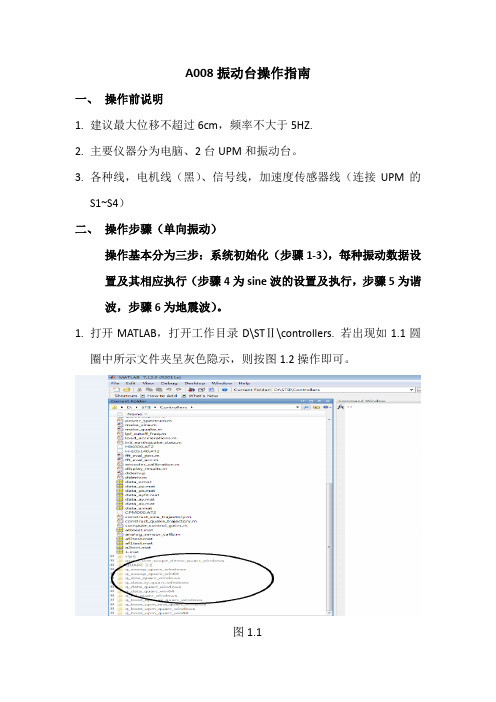
A008振动台操作指南一、操作前说明1.建议最大位移不超过6cm,频率不大于5HZ.2.主要仪器分为电脑、2台UPM和振动台。
3.各种线,电机线(黑)、信号线,加速度传感器线(连接UPM的S1~S4)二、操作步骤(单向振动)操作基本分为三步:系统初始化(步骤1-3),每种振动数据设置及其相应执行(步骤4为sine波的设置及执行,步骤5为谐波,步骤6为地震波)。
1.打开MATLAB,打开工作目录D\STⅡ\controllers. 若出现如1.1圆圈中所示文件夹呈灰色隐示,则按图1.2操作即可。
图1.1图1.22.打开setup.m,查看里面相关参数,之后点击图2.1中圆圈中按键。
图2.1然后,跳出图2.2,输入任意台面质量,之后输入y,如图2.2.3.初始化UPM. 首先打开UPM机后面的电源开关,Left和Right灯处于闪动状态,然后点击q_boot_upm.mdl。
如图3.1所示,点击QUARC里面的build选项。
图3.1完成后,点击图3.2圆圈里所示的连接键,之后点击连接键左边的竖三角按键,会显示UPM initialized. (此时UPM的Left和Right灯熄灭,home灯变绿色,说明振动台面居中,若home等未变绿,则可手动调整振动台面,使之居中)。
至此,UPM初始化完成。
(第一次初始化之后,后面的试验就不需要再进行这项操作了).图3.24.sine波的振动。
首先,打开q_sine.mdl,可以调节sine波的幅值和频率(一般开始取值均小于1为好)如图4.1. 然后进行编译,编译过程同图3.1和图3.2.图4.1sine波的数据采集。
图4.2右边黄色方块,X表示位移,a表示加速度。
图4.2双击X或a黄色方块,如图4.3(以加速度a为例)。
a0表示振动台加速度,分为a_table(g)(以g为单位)和a_table(m/s2)(正常单位),数据保存在右边的文件中,找到对应的文件名(如atbtest.mat)中。
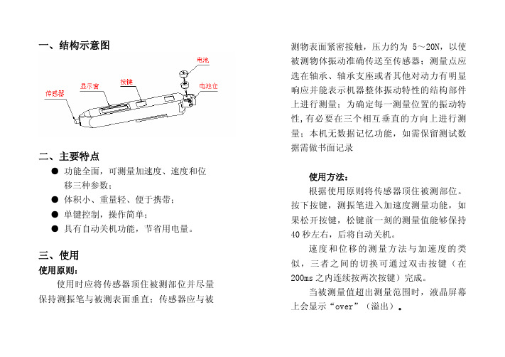
一、结构示意图二、主要特点●功能全面,可测量加速度、速度和位移三种参数;●体积小、重量轻、便于携带;●单键控制,操作简单;●具有自动关机功能,节省用电量。
三、使用使用原则:使用时应将传感器顶住被测部位并尽量保持测振笔与被测表面垂直;传感器应与被测物表面紧密接触,压力约为5~20N,以使被测物体振动准确传送至传感器;测量点应选在轴承、轴承支座或者其他对动力有明显响应并能表示机器整体振动特性的结构部件上进行测量;为确定每一测量位置的振动特性,有必要在三个相互垂直的方向上进行测量;本机无数据记忆功能,如需保留测试数据需做书面记录使用方法:根据使用原则将传感器顶住被测部位。
按下按键,测振笔进入加速度测量功能,如果松开按键,松键前一刻的测量值能够保持40秒左右,后将自动关机。
速度和位移的测量方法与加速度的类似,三者之间的切换可通过双击按键(在200ms 之内连续按两次按键)完成。
当被测量值超出测量范围时,液晶屏幕上会显示“over”(溢出)。
四、性能指标测量参数: ● 加速度●速 度●位 移测量范围: ● 加速度:0.01 m/s2~199.9m/s2(峰值)●速 度:0.01 mm/s~199.9mm/s(有效值)●位 移:0.001 mm~1.999mm(峰~峰值)频率范围: ● 加速度:10Hz~1kHz●速 度:10Hz~1kHz●位 移:10Hz~500Hz相对误差: ● 参考灵敏度不确定度≤3%;●幅值线性相对误差±5%±2个数;●频率响应相对误差:频率在10Hz≤f<20Hz为+10-20%,频率在20Hz≤f ≤1000Hz为±5%显示方式: 3位半液晶显示,显示周期约1s供电电源: 2节扣式电池(LR44或SR44) 电池寿命:连续工作时间约4.5h,待机时间约1年使用环境:温度0ºC~40ºC;相对湿度<85%外型尺寸:150mm × 22mm × 18mm整机重量:约55g(含两节电池)五、保养维护●TV260测振仪属精密仪器,应严格避免碰撞、潮湿、强电磁场、油污及灰尘;●更换电池应注意电池正极朝向“ ”;●如果较长时间不使用,应将电池取出;●请勿随意拆卸测振笔,以免损坏内部电路。
振动台抽风机
振
动
台
.功能
SVKD-3功率放大器机柜:通过接收和处理RVC-2A振动控制仪传递的信号数据,控制直振动台的运行。
4.3.将RVC-2A振动台抽风机的排气管通向窗外,并(借助窗户轻压于上)将其固定,以防试验中排气
管剧烈晃动。
5. 试验步骤
5.1.利用治具将试验样品固定于振动台台面,确保其固定牢靠。
5.2.将振动控制仪背部电源开关打开,振动控制仪
该设备已处于通电状态,则表示设备已经进入待机状态。
”键,抽风机运行,在按
上的信号调节器逆时针调到关闭状态,再按“”键关闭电源(此按键不能用来直接停止振动,待功率放大器机柜彻底冷却后(此过程大约8。
毅硕.仪器水平垂直电磁式振动台操作说明书上海毅硕实验仪器厂序言感谢您采用本公司高性能水平垂直电磁式振动台本产品采用高品质元器件,材料及融合最新的微计算机技术制造而成。
此产品说明书提供给使用者安装、参数设定、异常诊断排除、日常维护,及相关参数等。
为了确保正确地安装及使用本产品,请在装机之前,详细阅读说明书,并请妥善保存随机说明书。
水平垂直电磁式振动台控制器乃精密电子仪器。
为了操作者及机械设备的安全。
请务必由专业的工程人员安装操作。
并请正确调整参数。
本说明书中有[危险][注意]等符号的地方请务必仔细研读,若有任何疑虑的地方请联络本公司或各地代理商咨询。
我们的专业人员会乐于为您服务。
以下各项请使用者在操作本产品时特别留意注意➢台体连接配线时,必须关闭总电源。
➢切断交流电源后,控制器POWER指示灯(位于数字显示器下面),未熄灭前,表示控制器内部仍有高压十分危险,请勿插拔台体连接线。
指示灯完全熄灭后,方可进行操作。
➢绝不可自行拆卸改装控制器及配线。
➢控制器与台体务必正确接地。
230V系列采用第三种接地,460V系列采用特种接地。
➢本产品不能安装使用危及人身安全的场合。
➢请防止无关人员接近机器。
危险➢即使台体是静止的,控制器与台体连线仍然可能带有危险的电压。
➢只有受专业培训的人员方可安装操作,及维修保养。
➢当控制器某些功能被设定后,可能在输入电源后会让台体立即工作。
此时容易造成危险。
➢请选择安全的区域来安装本产品,防止高温及阳光直接照射,避免湿气或水滴的泼溅。
➢本产品安装时请符合注意事项,未经许可的使用环境可能导致火灾、气爆、感电等事故。
➢本产品安装之电源系统额定电压230V系列机种不可高于240V(460V 系列机种不可高于480V)。
电压系列接地工事的种类接地抵抗230V 第三种接地工事100欧姆以下460V 第三种特种接地工事10欧姆以下使用前注意事项交货检查★每台设备在出厂前均经过严格之品管,并做强化之防碰包装处理。
GKVT300-1500振动台使用说明书感谢贵公司使用本公司的产品,请在使用前务必阅读本说明书。
安全提示关于本产品的安全性已充分考虑。
请认真阅读本说明书后,正确使用本产品。
注意1请遵守铭牌上标示的电压作业。
如超过铭牌上标示的电压作业,可能会引起电器元件和马达的烧损,而使绝缘物被损坏导致触电的危险。
2 本产品为振动产品,为了避免振动马达产生共振、请确认加固加强后,正确的使用。
一旦产生共振其安装部,则可能会有损坏螺栓的松动或因折断而掉落的危险。
3 检查修修时,严禁在无侧盖的情况下开动马达,因为可能会有伤害事故的发生。
4在振动台顶升和夹紧部位作好防护,防止夹伤事故。
5变频器输出频率出厂时已调节好,请勿改变变频器的频率,如超过75Hz长时间使用的话,将会引起马达发热及轴承损坏等。
6 过电流保护装置的电流设定为额定电流的100~120%,请勿改变。
一.产品用途及使用范围1 本产品用于地铁盾构管片自动化生产线浇注用。
2 环境温度不超过40C,相对湿度不超过90%(温度不超过25C时),否则应降低功率使用;主机激振工率和运行电流不超过铭牌数值,否则应降低激振力使用。
二.主体结构及工作原理振动台台面尺寸:电源电压:AC380V总功率:12kW振动频率:50~70Hz台面振幅均匀度≤15%空载振动噪声≤100dB(A)振动时间按要求随意设置,最大振动时间为30分。
外形尺寸: 3505X2550X1300净重: 8 吨振动台主要分:底座、振动部分、夹紧装置,顶升气囔和振动电机,以及升降副轨。
振动台的工作原理主要是通过主控制柜检测到振动台的感应信息,模具到位时,副轨下降,使模具的轮子与模具分离,防止振坏轮子,顶升气囔充气顶升,然后夹紧模具,振动台振动部分与底座分离。
最后振动电机振动。
振动电机由特制电机外加激振重块组成。
当电机通电旋转时,激振块产生激振力,通过电机底脚或法兰盘传递纵横振动机械。
特制电机由特制定子线包和转子轴组成,能承受高频振动;卧式振动电机采用四块扇形偏心块作激振块,调节同轴端两块偏心块的夹角,可以从零至最大调节振动电机的激振力;立式振动电机,采用两块偏心块作为激振块,两轴端各一块,上轴端为固定偏心块,下轴端为可调偏心块。

振动试验台掌控器说明振动试验台如何操作振动试验台掌控器说明:本掌控器全铁盒封闭,具有掌控安全,操作简单,易懂.1. 电源开关:电源开关为红色船形按钮,掌控面板印有"ON"开,"OFF"关字样,按向"ON"方向为开,这时开关内指示灯会亮,(5000HZ除外)表示电源接通,按向"OFF"为关.2. 功能开关:波型选择为一绿色般形按钮,掌控面板上印有“全波”“半波”字样,按向“全波”方向为打开,可进行有关功能调整输出的运行,按向“半波”方向,只能做半波功能调整器的功能输出(L型除外)3. 三轴开关:三轴开关也为一绿色船形按钮,上方印有"水平"(X.Z轴)"垂直"(Y轴)字样,按向"垂直"方向为垂直输出,按向"水平"方向为水平输出.(依据机型来决议).4. 微调调幅调整:为一黑色圆形调整旋钮,上方有指示旋钮位置的刻度线,顺时针旋转可调大振幅,反之减小.(F型以上掌控器微调调幅调整0—10刻度为微调).5. 功能调整掌控器:它是振动机工作中枢所在,不同型号其构造,操作皆不相同,详见相应操作设定,通过其操作可作多种功能的运行.6. 电源插座:在掌控箱后部,接受带保险的三芯扁插座,以前为电流保险丝座.7.冲击功能:接受具有四芯孔的航空接头座,在冲击功能时把波型选择按向全波时输出,垂直,水平台面都可对接.再通过幅度调整来调整振幅.8. 垂直输出:接受具有四芯孔的航空接头座,在波型选择按向“全波”及三轴开关打到垂直方向时有输出,对应接到掌控箱后部接垂直台机的垂直输出口.9.水平输出:在掌控箱后部,接受具有四芯孔的航空接头座,在波型选择按向“全波”,三轴开关选择为水平方向时有输出,对应接水平台机的水平输出口.10.485通讯口:接受485通讯接口,在配置有电脑操作的机种中才有输出.欢迎新老顾客来电订购:电磁式振动试验台各项部件工作操作的说明电磁式振动试验台的功能与特点:1.反作用式机械振动,DC驱动可完成垂直和水平方向的正弦振动。
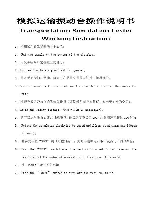
模拟运输振动台操作说明书Transportation Simulation TesterWorking Instruction1.将测试产品放置振动台中心位;1. Put the sample on the center of the platform;2.用扳手扭松开定位栏上的螺母;2. Unscrew the locating nut with a spanner;3.用双手平行拍打移动,将测试产品用夹具固定好后,扭紧螺母;3. Beat the sample with your hands and fix it with the fixture, then screw thenut;4.检查设备是否与别的物体有碰撞(该仪器四周必须要有0.5米至1米的空间);4. Check the safety distance (0.5 -1.0m is necessary).5.调节器从左往右加速,(注意事项:最低速度不低于100转,最高速不超过300转);5. Rotate the regulator clockwise to speed up(100rpm at minimum and 300rpmat most);6. 测试完毕按“STOP”键(红色灯亮),此时马达断电,取下试品记下测试数据;6. Push the “STOP” switch when the test is finished. Do not take out thesample until the motor stop completely, then take the record;7. 按“POWER”开关关闭电源.7. Push the “POWER” switch to turn off the tes t equipment.。
VIBCO’s vibratory flat top tables offer a fast, efficient and economical method for compacting a wide variety of mate-rials – powdery, granular or flaky – in boxes, drums or cartons.They are versatile and widely used for industrial appli-cations to package, shock and fatigue test and for densifying refractory blocks, concrete products.used as shakeouts for some foundry flasks.Let VIBCO quote you on your next table.A DESIGN TO MEET EVERY NEED:Low profile vegetable packerFertilizer bag packerPacking table with dualvibratorsPacking table withelectric vibratorTable with pneumaticvibrators & solenoidcontrolsT able for 5 ton concrete form8”dual table formarble sink topsSmall parts sorting table Electric, pneumatic or hydraulic vibratorLOW PROFILEDRUM PACKERLow profile drumoff floor -Adjustable brackets fordrums or boxesShock absorber to eliminatevibration transfer3-drum filling tableDrum packer, 24”x 32”x 3”, powered by two quiet Model BVS-570 Air Turbine Vibrators, for use in an explosive dust atmosphere.Load capacity up to 1200 lbs.Low weight Gaylord packerwith one vibratorGaylordpackingtable withrails forwood skid 8000 lbs.packing tableVIBCO’s Vibrating Drum Packer is a popular unit for densify-ing a wide range of material from spices to nails in drums or The V-shaped guide holds the drum in place and prevents it from vibrating off the platform.The SCR-DP tablelong and stands 3”off the floor.It can easi-ly be slipped under a filling station.The table is equipped with a 115 volt 1/2 HP 6.5 amp adjustable force and speed vibra-The low profile tables with two vibrators can be made to handle up to 10,000 lbs.of material.They stand 6”floor.See below for different styles.electric motorT ube constructionframe for strengthIncludes U.S.built VIBCO Heavy Duty Electric Motor Vibrators for vertical linear vibration.Standard vibrators offer adjustable force within a preset frequency.Variable force/speed control is an VIBCO has many years of experience in designing and building vibratory compaction tables for materials from oatmeal to concrete to sand, and even nuclear reactor waste.Each VIBCO vibratory compaction table is prop-erly designed for its purpose and expertly built.VIBCO Compaction Table Features:Vibco’s Grid T op tables incorporate the latest design features.They are functional and sturdy.Installed at the filling station on an in-line conveyor system, the mold or container is rolled into position over the grid while in low position.As the grid is being raised, filling begins and the vibrator is started.After mold or container is filled and densified, airmounts are deflated, placing the load on the conveyor where it is rolled forward and th next one is moved into filling position. Although these tables are of a standard shape and size, they can easily be adapted to fit your particular purpose with vibrators of different t frequencies and force output to match any job.Heavy duty electric,pneumatic or hydraulicvibratorsVIBCO’s GRID TOP TABLESare LIGHTER and STRONGERUsed in conjunction with roller conveyors for:Compaction of NO-BAKE sand in foundry flasks,casting concrete products, settling granular, flaky orpowdery materials in shipping containers etc.SizesVIBCO’s design utilizes high-strength tubular steel, which is 4x stronger and much lighter than the angle irons other The result is a more effective table.Less energy is absorbed by the dead weight of the grid top.No-bake sand compaction in foundry Grid table straddling scale Extended table base for scale Grid table straddling high floor scale High grid for high lift Drum packer in roller conveyor lineDetect Marginal ConnectionsVIBCO’s test tables result in savings on manufacturing costs, increased product reliability and greater customer con-fidence by detecting future failures right in your own plant, prior to shipment.Defective electrical components and connections fail under the induced vibration, helping you to quickly identify the problems.ing and costly repair and difficult tracing of circuits in the field.The simulation of transportation and handling shocks,on the Vibco test table give the added advantage of showing up the defective solder joints, marginal connections and Forces generated will not, however, effect components of sound integrity../ the vibration also removes potentially harmful residue such as pigtail clippings, solder splashes and other debris lodged in the chassis.are also extensively used in fatigue testing of many, varied electronic and space industry products, including:TVs, military hardware, lights, computers, etc.•Inexpensive Full Range ControlTABLE MODEL US-RD24”x 24”Standard US-TT T est T ables above are available with 6”x 12”, 12”x 12”, or 18”aluminum work -TT ables are ideal for testing printed circuits, plug boards and other small items.The US-TT table is supplied with SPC FREQUENCY (speed) control and a 115 volt 10,000 VPM (vibrations per minute) motor vibrator producing up to 100 designs, see below.6 x 1212 x 1218 x 18Table with hold-down clamps Pneumatic test table T able with outside railsUS-SA table with straps to hold test module to table top.Table with special controlcircuits.Vibrating table used to test density and material weight for each load.T able also test-ed for weldment cracks and fatigues during a normal 24 hour test -RD table testing electronicprosthesis.T able for reliability testing instru-ment packages.VIBRATING TEST TABLES BUILT TO MEET YOUR NEEDSSEE US AT 7902D VIBCO,West Coast:Phoenix, Arizona 85254Phone:(480) 596-1809(800) 633-0032FAX:(480) 596-1614Canada:2215 Dunwin DriveMississauga, Ont.L5L 1X1Phone:(905) 828-4191(800) 465-9709FAX:(905) 828-5015VIBCO, INC.75 Stilson Road, P .O.Box 8Wyoming, RI 02898E-Mail:*******************Phone:(401) 539-2392 / (800) 633-0032FAX:(401) 539-2584Vibrating roller conveyor in production lineAdjustable height table with railingFT 18”x 18”x 44”table with a variable high frequency vibrator for the making of molds for precision castings used in orthopedic surgery,such as hip joints, etc.Height was determined by a stationary microscope under which the work was done.Packing table for cartonsPneumatic vibrator on sorting tableTable to fit between large roller conveyor for packing gaylords on wood palletsShake out table with castersSmall carton packerDepeaking materials in carton before closing。
Seismic User ManualAIC调节Adaptive Inverse Control(AIC)是一种通过调整闭环系统的增益与相位规则,提高控制系统的保真度的一种控制补偿技术。
该方法可以有效地消弱多通道控制系统之间的交叉、耦合干扰。
使系统的输入与输出频响函数趋近于1。
适用于线性系统的非正弦波输入。
若输入信号为单纯正弦波,推荐使用Amplitude/Phase Control (APC),将更有效、更简单。
若系统为明显的非线性体系,建议AIC与OLI配合使用。
AIC调节时需要用到以下控制面板:·Main Panel 主面板·Function Generator panel 波形发生器·Spectrum Analyzer Panel 谱函数分析·Frequency Response Function(FRF)Plotter 频响函数曲线·Impulse Response Function(IRF)Plotter 脉冲响应函数曲线·Digital Oscilloscope 数字示波器AIC调节有它的频带宽度,最小频率与最大频率,建筑结构使用的地震波一般在0~25Hz之间,因此0~25 Hz的频响函数保证在1附近即可,其它将被视为噪声。
Impulse Response 脉冲响应长度,建议取2。
Anticipation 取Impulse Response/3 = 0.66 sec。
I/A=3合适Convergence Rate:0表示不调整;取值越高调整过程越快,但是传递函数的准确性降低;数值太高调整过程会发散。
取值小于1较为安全,一般可取0.02。
AIC Training Wizard(向导调节)是一种比较简单的自动调节方法。
1.点击主界面右边的AIC按钮,将其状态设置为Tracking。
2.主界面中Program Source项选择Function Generator的随机波进行AIC调节。
3.显示AIC窗口界面,点击下端Training Wizard按钮,显示AIC Training Wizard窗口。
设置Long、Lat、Vert三个自由度方向的加速度峰值(< 0.05g),输入每个自由度Training 的时间(越长越好,5min左右)、Final Convergence Rate(< 0.03),三个通道依次计算,Long、Lat、Vert自由度前的绿灯会依次亮。
点击Start,Forward Convergence Rate实时改变。
观察FRF Plotter窗口中的Long-Long、Lat- Lat、Vert-Vert传递函数曲线,趋近于1为最好。
4.若效果不理想,可再次修正Training Time与Final Convergence Rate参数,继续调整AIC。
5.在AIC调节的过程中,振动台面在随机波的驱动下,分别在Long、Lat、Vert三个自由度方向做单自由度运动,依次调节AIC。
6.调完后点击Multichannel AIC界面最下方的Calculate Inverse按钮,输入Number=2,Maximum=10,OK,进行计算。
观察Display中的Combine曲线,传递函数趋近于1。
7.用Date Player加地震波,进行试验预演Preview,观察Reference与Feedback曲线的位移、速度、加速度幅值不超限,用Desired span调整输入信号大小。
8.回到主界面右边的AIC按钮,将其状态改为Frozen,冻结即可,保存Setting文件。
OLI调节Online Iteration (OLI在线迭代)是一种使用反复迭代,使控制系统的反馈信号逐渐逼近其输入命令的一种实时迭代的信号控制技术。
该方法适用于明显非线性体系的非正弦周期波。
要做OLI,必须先做AIC调节,AIC状态必须为Frozen。
OLI的第一次迭代结果与AIC调节结果一致。
若输入波形为单纯正弦波,推荐使用Adaptive Harmonic Cancellation(AHC自适应消谐) 调节,将会更有效、更简单。
若系统不是显著的非线性体系,推荐使用Adaptive Inverse Control (AIC自适应逆控制)OLI中最重要的是两个时程数据文件:the desired file: 通过MTS振动台施加在实验对象上的原始输入波;the drive file: 经过数次迭代后,使反馈信号逐渐逼近输入信号(the desired file)的波形。
1.点击主界面右边的OLI按钮,将其状态设置为Training。
2.显示Online Iteration窗口界面,打开需要OLI调节的地震波文件Desired file,文件后缀一般为”.des”。
新建或打开一个驱动文件Drive file,文件后缀自动生成为” .d01”,Drive update file的后缀在Drive file的基础上自动累加” .d02”。
3.输入迭代系数Iteration gain(0.1左右,越小收敛越好),取值为0~1。
4.按下Start按钮开始第一次迭代,完成后Drive file名变为***.d02,Drive update file名变为***.d03,第一次迭代结束。
再次Start则振动台在***.d02的驱动下运行,记录三个自由度方向的Reference与Feedback信号,同时进行第二次迭代,又生成***.d03的驱动文件;观察比较***.d02驱动时的Reference与Feedback信号,或者观察Long-Long、Lat-Lat、Vert-Vert的传递函数,如果效果不够好可以再次迭代,如果效果很好就将***.d02的文件保存,将OLI的状态设置为Frozen。
5.今后就用***.d02的文件进行振动台试验的输入,OLI调节到此结束。
OLI调节时的Desired file加速度幅值不易太大,尽量避免试件损伤。
经过AIC、OLI调节后,AIC、OLI的状态都需要修改为Frozen,用调节后的***.d02文件作为地震输入波,需要在Online Iteration界面下操作地震输入,不能再用Date Player加地震波了。
关闭单一自由度Date Player File菜单下的Function Generator里,Select按钮选择某一个自由度,再点击下面的Stop/ Run按钮,就可以关闭/开启单一自由度了。
在Date Player界面中,有选择自由度的列表,挑选需要的自由度从左边转移到右边列表,就可以选定台面运行的自由度。
发地震波Date Player page 69Date Player界面1.从左边Available列表中,挑选需要的自由度,移动至右边Selected列表。
自由度的数量、顺序必须与File文件中的数量、顺序一致。
2.点击左上角File按钮,选择需要驱动台面的地震波数据文件。
该文件格式为MTS认可的.bin。
可用文件格式转换器将ASCII的文本文件转换为MTS的二进制文件。
3.参数File Sample Period为文件中的数据采样时间间隔,单位second。
采样频率最大为2048Hz。
参数Play Sample Period为发送地震波时的时间间隔,单位second。
一般与File Sample Period一致。
参数File Length为一次地震波运行的时间,单位h:m:s。
参数Elapsed Time为总的运行时间,单位h:m:s。
参数Pass __ of __ 为地震波循环的次数,可连续重复驱动振动台面。
ASCII的文本文件格式为:1.第一个值为采样时间间隔File Sample Period,单位second。
2.地震波数据按自由度列表显示,一列为一个自由度,单位为其工程单位g。
3.转换后的文件与ASCII的文本文件.txt同名,后缀变为.bin。
数据记录Date Recorder page 71Date Player界面1.从左边Available列表中,挑选需要记录的各通道信号,移动至右边Selected列表。
2.点击左上角Sample Rate按钮,设置此次记录的采样频率,最大为2048Hz。
3.点击File按钮,输入数据保存文件名及其路径。
该文件格式为MTS认可的二进制文件.bin。
可用文件格式转换器将MTS的二进制文件转换为文本文件。
4.参数Starting delay: 当按下Run / Start按钮后数据延时记录的时间,单位second。
参数Recording Period: 记录数据的时间总长,单位second。
参数Comment: 文件备注信息。
5.单选项Enable AA Filters: 系统软件会根据采样频率为每一个信号进行适当的滤波,AA滤波器的频响特性会在FRF窗口显示。
并需要设置滤波延时时间。
单选项Synchronize with Run: 同步触发记录数据。
单选项Loop forever: 循环记录。
记录数据的工程单位:位移/mm,力/ kN,速度/ m/s,加速度/ g数字仪表Digital Meter A or B page 73主控制面板Display菜单下的Digital Meter A与Digital Meter A选项。
该界面可监控Ch A或Ch B信号的当前数值。
Max/Min:最大/最小值Peak/Valley(Banded)峰值,适用于周期波或非周期波。
Peak/Valley(Timed)峰值,只适用于周期波。
数字示波器Digital Oscilloscope page 76该示波器可同时显示Ch A与Ch B两个通道的曲线。
Sweep Period:右边画面可显示的最长时间段,即横坐标最大值。
A-B Delay:两条曲线之间的延时差。
Autoscale单选项:两条曲线按各自比例,放大至同一画面。
Same scale单选项:按同一比例显示。
Display Mode:显示类型Time:时域;Freq:频域;X-Y:ChA-ChB图形显示区域:左边三个文本编辑框中,可以输入ChA的坐标轴显示范围,右边三个文本编辑框中,可以输入ChB的坐标轴显示范围,下方三个文本编辑框中,可以输入X的坐标轴显示范围。
频响函数图表Frequency Response Function Plotter page 81一般用于AIC调节或AHC控制。
可显示所选信号的频响特性,也可用于谱函数分析FRF。
469D主控制面板—Display菜单下—FRF Plotter选项,打开FRF Plotter 面板。