蒙特纳利MCK系列曳引机使用说明书
- 格式:pdf
- 大小:893.79 KB
- 文档页数:18

YTW220-G2D 系列永磁无齿轮曳引机使用、维护手册注意!⏹请详细阅读本手册,以免发生设备损坏和人员伤害的危险。
⏹为了保证电梯能安全、可靠、高品质地运行,从事电梯安装、调试、运行、检查、保养和维修的人员必须是具备专业知识的人员,熟悉电梯产品的安装、调试和使用,并对电梯的构造有充分的了解。
⏹本手册由于产品改进、规格变更,以及为了手册本身使用方便,可能会有适当的改动。
⏹请将本手册交给最终用户(安装、运行、检查、保养、维修)手中,并请妥善保存。
沈阳优力维特电梯制造厂资料编号:TM-05161目录1.前言 (4)2.安全符号说明 (5)3.安全方面的注意事项 (6)4.开箱时的确认事项 (11)4.1开箱时请确认以下项目 (11)5.搬运时的注意事项 (12)5.1产品搬运 (12)5.2吊装示意图 (13)6.存储 (14)6.1存储检查 (14)6.2长期存储后的检查 (15)7.产品结构特点 (16)7.1结构 (16)7.2产品外形尺寸 (17)8.工作原理 (18)9.使用环境 (19)10.技术参数 (20)11.编码器的使用 (21)11.1编码器的使用类型 (21)11.2 编码器的连线 (22)12.使用前的检查 (24)13.曳引机的安装 (25)14.手动松闸和手动盘车装臵的使用 (27)14.1棘轮式手动盘车装臵 (27)14.2涡轮涡杆式手动盘车装臵 (27)14.3其他注意事项 (28)15.运转 (29)15.1连线 (29)15.2 运转 (30)16.维护与保养 (32)16.1日常维护 (32)16.2.部件检查 (33)16.3制动器的调节: (33)17. 曳引机常见故障及处理 (36)18. 易损件明细表 (37)19.质量保证 (38)1.前言⏹首先感谢您使用我们公司的产品,我们将竭诚为您提供优质服务。
⏹YTW220-G2D系列永磁无齿轮曳引机设计、生产符合《EN81-1:1998》、《GB7588-2003》、《GB/T13435-92》中的各项规定。

永磁同步无齿轮曳引机MONA系列使用说明书请将此说明书交至最终用户(安装、使用、维护、保养等)手中并请妥善保存。
V201910前言非常感谢您选用本公司产品,我们将竭诚为您提供优质服务。
本司永磁同步无齿轮曳引机(以下简称曳引机)采用了先进的设计理念和制造工艺,产品具有结构紧凑、体积小、重量轻、能耗低、噪声小、效率高等特点。
本司曳引机设计、生产符合《GB7588-2003-电梯制造与安装安全规范》、《EN81-1:1998-电梯建造和安装的安全规则》、《GB/T24478-2009-电梯曳引机》中的各项有关规定。
本使用说明书叙述了正确使用本曳引机的方法,本说明书中的图示为代表性事例,与实际产品可能会有所不同。
一般注意事项1.本说明书因产品改进、规格变更及为了使说明书本身使用方便,会有适当的改动,本司保留对说明书的修改权利,内容如有变更,恕不另行通知。
2.开箱后请确认产品是否和订单的型号、规格一致。
误使用了不同的产品可能使电梯或曳引机等破损、人员伤亡的危险。
3.请根据产品铭牌上注明的重量和手册中规定的吊装方法仔细核实吊具的额定载重,吊具载重量不足时有产品坠落、翻到和人员伤亡的危险。
4.如遇资料损坏、遗失、产品铭牌字迹模糊破损时,请按封底上联系方式向本司订购。
警告:安全说明①安装、使用、维护及保养前,请认真阅读本说明书及相关附属资料,以免造成设备损坏,引起人员伤亡。
②安装、使用、维护及保养过程中,请严格按照本说明书规程操作,以确保设备正常及人身安全。
③本说明书中所示的图解为了说明细节部分,有将外壳或为了安全的遮盖物去除状态下描述的,本产品在运行前,务必按规定将外壳或遮盖物复原后按使用说明书操作运行。
④非专业人员严禁操作。
通用安全注意事项打上安全符号的段落、语句叙述了重要的内容请一定要遵守,错误使用时可能导致人身伤害和设备损害,错误使用严重时可能会导致人身伤亡!搬运、安装、接线、运行、操作、检查、维护、保养请由具备专业人员来进行。

通力电梯技能培训教材系列T1-EL-04-M02课程描述课程编号: T1- EL- 04- M02课程名称: 曳引机、曳引机底座及导向轮课程内容: 1. 曳引机外观检查(生锈、螺丝松紧、铭牌)2. 曳引机垂直度检查3. 曳引机风扇检查更换(MX18/20/32/40/100)4. 曳引机钢丝绳防跳、防夹手装置检查、调整(MX06/10/14/18/20/32/40/100)5. 曳引机导向轮垂直度检查6. 曳引轮与导向轮平行度、垂直度检查7. 导向轮挂脚(导向轮方向)检查8. 导向轮防跳装置检查、调整9.MONOSPACE电梯马达底座、减震垫检查(MX10, MX20)10. MINISPACE电梯马达底座、减震垫检查(MX18, MX14, MX32)11. MINISPACE电梯马达底座承重(水泥敦)梁检查12. S/X MINISPACE电梯底座、减震垫检查(MX10侧置对重)13.SMINISPACE电梯减震垫检查(MX10后置对重)课程对象: 新入职三个月内的调试员课程目标: 通过培训能够使调试员对曳引机进行检查及调整所需设备: 投影仪、白板、实物推荐课时: 课堂: 2.0 h 现场实践: 2.0 h 更新人:David Chung 审核人:Zhu Yong Xiang 更新日: 20 Jun 2011 审核日期:31 JUN 2011目录第1章曳引机外观检查 ...................................................................................................................... - 2 -1.曳引机外观检查 .......................................................................................................................... - 2 -1.1主體.................................................................................................................................. - 2 -1.2锈蚀和磨損、檢查 .......................................................................................................... - 2 -1.3潤滑物.............................................................................................................................. - 2 -1.4铭牌.................................................................................................................................. - 2 - 第2章曳引机垂直度检查 .................................................................................................................. - 2 -1.曳引机垂直度检查 ...................................................................................................................... - 2 - 第3章曳引机风扇检查更换 .............................................................................................................. - 2 -1.曳引机风扇检查更换 .................................................................................................................. - 2 -1.1描述.................................................................................................................................. - 2 -1.2检查内容 .......................................................................................................................... - 2 -1.3常见风扇的种类 .............................................................................................................. - 2 -1.4风扇更换 .......................................................................................................................... - 2 - 第4章曳引机钢丝绳防跳、防夹手装置检查、调整 ...................................................................... - 2 -1.曳引机钢丝绳防跳装置和防夹手装置 ...................................................................................... - 2 -1.1曳引机钢丝绳防跳功能介绍 .......................................................................................... - 2 -1.2曳引机钢丝绳防跳装置的检查、调整 .......................................................................... - 2 -1.3防夹手装置功能介绍 ...................................................................................................... - 2 -1.4防夹手装置的调整 .......................................................................................................... - 2 - 第5章曳引机导向轮垂直度检查 ...................................................................................................... - 2 -1.曳引机导向轮垂直度检查 .......................................................................................................... - 2 - 第6章曳引轮与导向轮平行度、垂直度检查 .................................................................................. - 2 -1.曳引轮绳槽中心与导向轮绳槽中心检查 .................................................................................. - 2 -1.1水平度.............................................................................................................................. - 2 -1.2牽引輪和导向轮中心界線 .............................................................................................. - 2 -1.3繩索開槽中心線 .............................................................................................................. - 2 - 第7章导向轮挂脚(导向轮方向)检查 .......................................................................................... - 2 -1.导向轮挂脚(导向轮方向)检查 .............................................................................................. - 2 - 第8章导向轮防跳装置检查、调整 .................................................................................................. - 2 - 第9章MONOSPACE电梯马达底座、减震垫检查......................................................................... - 2 - 第10章MINISPACE电梯马达底座、减震垫检查 ............................................................................ - 2 - 第11章MINISPACE电梯马达底座承重(水泥敦)梁检查 ............................................................ - 2 - 第12章S/X MINISPACE电梯底座、减震垫检查............................................................................. - 2 - 第13章SMINISPACE电梯减震垫检查(MX10后置对重)........................................................... - 2 -第1章曳引机外观检查1. 曳引机外观检查在进行下述带电部件的检查和更换工作时,要特别小心参照AM-01.03.002文件。

WSG-09操作和维护说明书 J40003日期01.03.2013版本AWITTUR Holding GmbH威特集团Rohrbachstrase 26-30 . D-85259 Wiedenzhausen, Germany电话/ Tel. +49 (0) 81 34/18-0 •传真/ Fax +49 (0) 81 34/18-49,E-mail:***************未经威特集团事先书面许可,不得以任何形式重印、翻译或复制本说明书的部分或全部内容。
威特集团保留对本操作说明书所包含信息和图片进行更改的权利,恕不事先通知。
WSG-09操作和维护说明书 J40003日期 01.03.2013版本 A威特电梯部件(苏州)有限公司中国江苏省吴江汾湖经济开发区厍星路18号电话 +86-512-82072888传真 +86-512-63220044***************.cn本操作手册适用于电梯曳引机:WSG - 09. X 系列带块式制动器威特集团保留纠正或更改本操作手册内容以及产品详情的权利,恕不事先通知。
我方明确保留进行改进曳引机或其安全标准的技术变更的权利,恕不事先通知。
若未能遵守本操作手册规定而产生的任何损坏、伤害或费用,我方不承担任何责任。
对于详细信息的正确性和完整性,我方不提供任何担保。
WSG-09操作和维护说明书 J40003日期01.03.2013版本A目录1. 一般安全说明 (4)2. 产品描述 (5)3. 铭牌 (6)4. 型号说明 (7)5. 技术数据 (8)6. 尺寸图 (10)7. 供货范围 (11)8. 运输和储存 (11)9. 安装 (12)10. 电气连接 (13)10.1. 概述 (13)10.2. 电机连接/ 绕组保护 (13)10.3. 速度/ 位置测量系统 (15)10.3.1. 编码器ECN1313 ENDT 信号表 (16)10.3.2. 测量系统 (16)10.4. 监控制动器 (17)11. 调试..........................................................................................18 12. 操作与维护 (19)12.1. 概述 (19)12.2. 维护间隔期 (19)12.3. 润滑说明 (20)12.4. 远程松闸装置 (20)12.5. 盘车装置 (21)12.6. 更换曳引轮 (21)12.7. 制动器 (22)12.8. 重新安装编码器系统 (25)12.9. 故障排除 (26)13. 附件 (27)13.1. 编码器线 (27)13.2. 盘车手轮 (27)13.3. 远程松闸 (27)13.4. 松闸扳手 (27)13.5. 盘车齿轮 (27)14. 备品备件清单 (28)WSG-09操作和维护说明书 J40003日期 01.03.2013版本 A1. 一般安全说明对本说明书中所使用符号的解释指不采取适当的预防措施造成人员伤亡或者财产严重损坏。
曳引机使用说明书安全可靠人性创新永磁同步无齿轮曳引机MTA50000AB序言感谢您使用该系列永磁同步无齿轮曳引机产品!永磁同步电机技术作为一种电动机新技术应用于电梯曳引机领域开始于二十世纪九十年代,它带来了一次电梯公司形式上的革命。
该系列永磁同步无齿轮曳引机采用盘式制动器、内转子型式。
本公司研发的永磁同步无齿轮曳引机的各项指标设计均符合国家相关规定,每台曳引机出厂前都经过严格的质量检验,对制动力、绝缘耐压、振动、噪音等各项指标进行了全面的检测,从而保证产品的质量和性能符合标准规定。
此手册为产品的一部分,旨在为用户正确使用无齿轮曳引机并提供曳引机安装、保养方面的指导,请务必妥善保管于安全的地方,以方便服务人员使用。
在对机器进行安装、调试、使用、维修前,请务必阅读并理解此手册的内容。
对不按此手册或不按我公司工程人员指导进行违规操作所产生的所有后果,我公司有权不予承担。
我公司拥有对本手册及其所包含信息的所有权,并有权对手册内容进行版本更新,而不另行通知。
严禁任何单位和个人,不经本公司同意复制部分或全部内容,用于同行业产品的说明和介绍。
目录序言一安全 ........................................................................................................ - 1 -二产品说明 ................................................................................................ - 1 -2.1曳引机介绍 (1)2.2曳引机工作条件 (1)2.3防护等级 (1)2.4产品型号 (2)2.5外形安装尺寸 (2)2.6备件 (3)三运输、仓储及吊装 ................................................................................. - 3 -四安装 ........................................................................................................ - 4 -4.1使用前检查 (4)4.2安装注意事项 (4)4.3远程松闸手动装置的安装及使用说明 (4)4.3.1 安装 ................................................................................................ - 4 -4.3.2 使用说明 ........................................................................................ - 5 -4.5编码器 (7)4.5.1编码器ERN1387 (7)4.5.1.1编码器ERN1387的安装及拆卸 (8)4.5.1.2编码器的连接 (8)4.5.2汇通编码器 (9)4.5.2.1编码器的连接 (10)4.5.3多摩川编码器 (10)4.5.3.1多摩川编码器安装及拆卸 (10)4.5.3.2编码器的连接 (10)4.5.4亨士乐编码器....................................................................................... - 10 - 4.6制动器的安装及调试 .. (7)4.6.1制动器注意事项 ........................................................................... - 11 -4.6.2制动器的拆卸 ............................................................................... - 11 -4.6.3制动器的安装 ............................................................................... - 11 -4.6.4制动器的调试 ............................................................................... - 12 - 4.7盘车开关的安装及使用 . (7)五维护 ...................................................................................................... - 13 -5.1日常维护 .. (13)5.2电机维护 (13)5.4曳引轮维护 (14)六常见故障的处理方法 ........................................................................... - 14 -一安全以下为本操作手册内所使用的图片和表示的意义,请仔细阅读。


二、规格型号、技术参数说明1) 直梯有齿曳引机的型号由以下符号组成YJ □△Y——曳引机J——交流电源□——曳引机减速器中心矩(mm)△——变型更新代号,用A、B、C……表示2)产品铭牌构成(如下图)3)技术参数YJ240系列曳引机型号YJ240A-ⅡYJ240A-ⅡYJ240A-ⅢYJ240B-ⅠYJ240B-ⅡYJ240B-ⅢYJ240B-ⅢYJ160系列三、工作条件1、海拔高度不超过1000米;2、机房内空气温度应保持在+5~+40℃之间,相对湿度不大于90%;3、环境空气中不含有腐蚀性、易燃性气体;4、供电电压保持在380±7% V,频率为50Hz;5、机房内要求有良好的照明和消防设施。
四、主要结构及工作原理本曳引机主要由电机、减速箱、制动器、曳引轮、轴承架、加高台等零部件组成。
工作原理:通电时,电磁制动器动作使制动部件对制动轮松闸,同时主动力由电机经联轴器传至蜗轮减速箱的蜗杆轴,蜗杆带动蜗轮,使与蜗轮同轴的曳引轮同步旋转,并通过钢丝绳与曳引轮绳槽间产生的相对静摩擦力来实现电梯轿厢的升降运行;零速时,电磁线圈失磁,制动器抱闸制动。
五、吊运安装a) 运输、存储的工作环境条件:-25℃~55℃/70℃。
b) 吊运:已装箱的曳引机应按吊装规范同包装箱整体吊装至机房,拆箱后需要起吊时在吊环处吊运。
见附图c) 注意:曳引机出厂前已装配调试检验合格,用户不得随意拆开吊装。
d) 安装:曳引机机架的安装尺寸如附图一所示,曳引机、导向轮、加高台等系统部件与搁机梁之间的安装关系如附图二所示(该系统图仅供参考)。
e) 搁机梁采用普通工字钢或槽钢,其强度必须符合电梯标准的有关规定,安装精度不大于千分之一。
f) 加高台安装底面与四只减震垫在安装螺栓拧紧前用塞尺检查,结合面不允许有间隙。
六、使用与维护a) 曳引机外表面应保持清洁,防止灰尘污垢。
定期用干净的棉纱擦拭制动轮、曳引轮工作面。
b) 制动器:i. 制动时闸瓦应均匀紧贴制动轮表面,松闸后闸瓦与制动轮之间的间隙应小于0.5mm,且无局部接触。
GB 7588-2003eqv EN 81-1:1998 代替 GB7588-1995· 非常感谢电梯用户和电梯业同仁,对凯迪电梯设备有限责任公司出品的高效节能型曳引机产品的青睐和厚爱。
· 请在曳引机安装调试前,细心阅读本手册,以便正确安装、调试、检查使用永磁同步行星曳引机产品。
· 本公司产品于2005年6月已在中国和国际市场投放KD ·Y160、KD ·Y280系列产品。
2006年1月新增KD ·Y395系列产品,上述三大系列产品具有第五代曳引机极其完美的技术性能,其技术条件和检验标准已按下述标准执行:《GB/T7588—2003 中华人民共和国国家标准》《TSG 特种设备安全技术规范TSG T7017-2004电梯曳引机型式试验细则》、《电梯制造与安装安全规范》· 在执行出厂检验标准过程中,产品批量条件下的生产内控指标为: 1. 曳引机扭转振动速度有效值不超过3.5(加载20—40%)。
2。
加载条件下机房噪音(dB )最大值不超过62分贝。
· 上述产品均已通过国家电梯质量监督检测中心进行型式试验的检测。
· 本公司对手册的相关内容有权进行修改,恕不另行通知,如需进一步了解,请登陆www.woducom 。
com/kddt ,查询相关信息。
柳州凯迪电梯设备有限责任公司2006年1月1日目录●产品技术特点 (1)●曳引机配置技术参数适用范围 (1)●永磁电机、变频器、编码器的选型与匹配性能的机理 (2)●凯迪电梯曳引机的三个技术优势 (2)●凯迪曳引电机与八种变频器的配合选型说明 (3)●正确选择:信号反馈元件-编码器 (3)●曳引机铭牌的技术参数与相互之间的关系 (4)●变频器对电机的自学习 (5)●电机过热保护 (5)●节能型制动器简介 (6)●盘车装置与安全回路开关的切断 (7)●手动远距离拉闸与电动平层 (7)●平层制动阻力 (7)●解救方法 (8)●绳轮的防护 (8)●润滑油的更换 (8)●机器的运输和固定 (9)●曳引机安装尺寸图 (9)●产品技术特点永磁行星曳引机是通过变频调速器输出的矢量电流,并依据时序按设定的运行曲线,对曳引机进行起动、运行、制停过程的适时控制。


K1.0 SERIES TECHNICAL GUIDEK1.0L, K1.0L SLNOTES:Specifications are affected by the condition of the vehicle and how it is equipped, as well as the nature and condition of the operating area. Inform your dealer of the nature and condition of the intended operating area when purchasing your Hyster ® truck.(1) N ote for SL model:With Fem like carriage and forks 80 x 30 mm + 20 mm With Fem like carriage and forks 100 x 35 mm + 25 mm(2) Note for models with over head guard: with lift interrupt mounted on OHG h6+ 80 mm (3) Note for SL model: With Fem like carriage and forks 80 x 30 mm and 100 x 35 mm h13= 40 mm (4) Note for SL model: with Fem like carriage b2= 800 mm(5) Note for SL model:Available also Fem like carriage and fork size 80 x 30 mm (600 Kg @ 600 mm,800 Kg @ 500 mm, 1000 Kg @ 400 mm) and 100 x 35 mm with 1000 Kg @ 600 mm (6) Note for SL model: with Fem like carriage b3= 800 mm (7)N ote for SL model: With Fem like carriage and forks 80 x 30 mm b5= 753 mm With Fem like carriage and forks 100 x 35 mm b5= 773 mm (8) With wire guidance l1 and l2 + 40mm (9) These values may vary of +/- 5%(10) Available battery 560Ah. With battery 560Ah service weight -9kg(11) Model without cabin; the value is referred to the overall height, without load backrest (12) Models name referred to h12Specification data is based on VDI 2198.Safety: This truck conforms to the current EU requirements.G E N E R A L 1-1Manufacturer HYSTER HYSTER HYSTER HYSTER 1-2Model designation K1.0L AC 0.7 FC K1.0L AC 1.4 FCK1.0L AC 1.2K1.0L AC 1.2 SL1-3DriveBattery Battery Battery 1-4Operator typeOrder-pickerOrder-pickerOrder-picker1-5Rated capacity / rated load Q 1t 1111-6Load centre distancec mm 6006006001-8Load distance, centre of drive axle to fork (1)x mm 144961661-9Wheelbaseymm 1390139013902-1Service weight (9) (10)kg 1550175016001700Specification data is based on VDI 2198.Safety: This truck conforms to the current EU requirements.G E N E R A L1-1Manufacturer HYSTER HYSTER HYSTER HYSTER1-2Model designation K1.0L AC 1.7 SL (13)K1.0L AC 1.7 WP (14)K1.0L AC 4.8 SL (15)K1.0L AC 4.8 WP 1-3DriveBattery Battery Battery Battery 1-4Operator typeOrder-picker Order-picker Order-picker Order-picker1-5Rated capacity / rated load Q 1t 11111-6Load centre distancec mm 6006006006001-8Load distance, centre of drive axle to fork (1)x mm 1661661571661-9Wheelbaseymm 13901390151015102-1Service weight (9) (10)kg 1800200027362875NOTES:(13) Available models K1.0L AC 1.9 SL / MO10E AC 19 SL(14) Available models K1.0L AC 1.9 WP / MO10E AC 19 WP(15) Available models K1.0L AC 3.2-3.6-4.0-4.4 SL / MO10E AC 32-36-40-44 SL (16) Available models K1.0L AC 3.2-3.6-4.0-4.4 WP / MO10E AC 32-36-40-44 WP (17) T ransfer aisle widths (lines 4.34.1 & 4.34.2) are based on the VDI standardcalculation as shown on illustration. The British Industrial Truck Associationrecommends the addition of 100 mm to the total clearance (dimension a) for extra operating margin at the rear of the truck.NOTICE:Care must be exercised when handling elevated loads. Operators must be trained and must read, understand and follow the instructions contained in the Operating Manual.All values are nominal values and they are subject to tolerances. For further information, please contact the manufacturer.Hyster products are subject to change without notice. Lift trucks illustrated may feature optional equipment. Values may vary with alternative configurations.m h l lh13h y xl c1035h sb Astb eb b Ast WaRa/2a/2a/2b /b a/2Qm h l 1767lh h y 1390xl 1035h sa/2a/2WaRa/2a/2b Astb b b Ast b /b cQValues shown are for standard equipment. When using non-standard equipment these values may change. Please contact your Hyster dealer for information.K1.0L AC 0.7 FCK1.0L AC 1.4 FCMAST INFORMATION – K1.0L, K1.0L SL, K1.0L WPTRUCK DIMENSIONSLift height h3 mmFree Lift h2 mm (1) (2)Height, mast loweredh1 mmHeight, mast extendedh4 mmHeight, overhead guardh12 mmWeight (3)1-S T A G E L I M I T E D F R E E L I F T10101780165426641190-15302300227038001710-16902460227039601870-Lift height h3 mm Free Lift h2 mm Height, mast loweredh1 mm (1) (2)Height, mast extendedh4 mmHeight, overhead guardh6 mmWeight (3)2-S T A G E L I M I T E D F R E E L I F T30283798227552983208-34284198247556983608-38284598267560984008-42284998287564984408-46285398307568984808-MASTS – 1 STAGE LFLMASTS – 2 STAGE LFL SL(1) For models WP -690mm(2) Note for SL model: with Fem like carriage and forks 80 x 30 mm and 100 x 35 mm H -40 mm(3) All weights are: mast structures (weldment, cylinders, chain, pulley) + oil EXCLUDED: forks, accessoriesAll values are nominal values and they are subject to tolerances. For further information, please contact the manufacturer. Hyster products might be subject to change without notice. Lift trucks illustrated may feature optional equipment. Values may vary with alternative configurations.5m /m h h xl h y h h h seb WaRb /b l lb b l AstAst a/2a/2a/2a/2cQK10L AC 12m /m h h y h Wab /b AstAst 3a/2lsh h Rb l b ecb b xl l ha/2a/2a/2QK1.0L AC 1.2K1.0L AC 1.2 SL6K10L AC 17 SLY h m /m h h /h h b /b WaRb Asta/2a/2l a/2Ast a/2b b l h h sll cxe996K1.0L AC 1.9 SLK1.0L AC 1.9 WPTRUCK DIMENSIONS7a/2a/2l 1y xll 2m1/m2h 7h 13h 9h 3h 6h 1h 4h 12Ast 3scWa Rb 6a/2Asta/2b 5b 3b1/b2b 11el 6QK1.0L AC 4.8 SL8a/2a/2y m1/m 2h 7h 6h 1h 4h 12Ast 3WaRAstb1/b2b 5eb 6l 6a/2996a/2b 11xcsh 13h 3ll 2l 1QK10L AC 48 WPK1.0L AC 4.8 WPTRUCK DIMENSIONSNOTES:Specifications are affected by the condition of the vehicle and how it is equipped, as well as the nature and condition of the operating area. Inform your dealer of the nature and condition of the intended operating area when purchasing your Hyster® truck.(1)W ith Fem like carriage and Forks 100x35 add + 25mm(2)With TX mast add 55mm(3)With DX mast reduce 55mm(4)W ith Lift interrup mounted on OHG: h6 e h4 are increased by 105mm(5)W ith flashing light fitted on Over Head Guard: h6 e h4 are increased by 120 mm(6)W ith Fem like carriage and Forks 80x30 and 100x35 h13 = 40 mm(7)A vailable also Fem like carriage and fork size 100x35 with 1000 Kg @ 600 mm(8)With Fem like carriage b3 = 800mm(9)W ith Fem like carriage and Forks 100x35 b5 max = 773mm(10)Sensor height 30mm from the ground(11)Additional batterie available: 48/280 (541kg)(12)Additional batterie available: 48/420 (746kg)(13)Additional batterie available: 48/560 (937kg)(14)Available 700mm and 860mm(15)Available 520mm, 680mm, 830mm(16)Available 1075mm and 1330mm(17)Available 1175mm and 1430mm(18)These values may vary of +/- 5%(19)T ransfer aisle widths (lines 4.34.1 & 4.34.2) are based on the VDI standard calculationas shown on illustration. The British Industrial Truck Association recommends the addition of 100 mm to the total clearance (dimension a) for extra operating margin at the rear of the truck.NOTICE:Care must be exercised when handling elevated loads. Operators must be trained and must read, understand and follow the instructions contained in the Operating Manual. All values are nominal values and they are subject to tolerances. For further information, please contact the manufacturer. Hyster products are subject to change without notice. Lift trucks illustrated may feature optional equipment. Values may vary with alternative configurations.Specification data is based on VDI 2198.Safety: This truck conforms to the current EU requirements.10b1a/2a/2Ast 3WaRl 2l 6lAstb 5eb 3b 2b 11h 4h 1222.5y xm1/m2h 7907.0HEIGHTsh 9h 3h 12Hh 13h 6201BATTERY HEIGHTK1.0M-K1.0HK1.0M-K1.0H2051.0OHG HEIGHT907.0GUARD TRUCK DIMENSIONS(2) Note for SL model: with Fem like carriage and Forks 80x30 and 100x35 H -40 mm(2) Note for SL model: with Fem like carriage and Forks 80x30 and 100x35 H -40 mmAll values are nominal values and they are subject to tolerances. For further information, please contact the manufacturer.Hyster products might be subject to change without notice. Lift trucks illustrated may feature optional equipment. Values may vary with alternative configurations.MASTS – 3 STAGE SLLift height h3 mmFree Lift h2 mm (1) (2)Height, mast loweredh1 mmHeight, mast extendedh4 mmHeight, overhead guardh12 mm3-S T A G E48455695 (1)2370721550954995584524207365524551455995 (1))24707515539552956145252076655545544562952570781556955595644526207965584557456595 (1)26708115599558956745272082656145604568952770841562956195704528208565644563457195 (1)28708715659564957345292088656745664574952970901568956795764530209165704569457795 (1)30709315719570957945312094657345724580953170961574957395824532209765764575458395 (1)32709915779576958545332010065794578458695337010215809579958845342010365824581458995 (1)347010515839582959145352010665854584459295357010815869585959445362010965884587459595 (1)3670111158995889597453720112659145K1.0H WP 1-11-21-3NOTES:Specifications are affected by the condition of the vehicle and how it is equipped, as well as the nature and condition of the operating area. Inform your dealer of the nature and condition of the intended operating area when purchasing your Hyster® truck.(1)W ith Lift interrup mounted on OHG: h6 e h4 are increased by 105mm(2)With flashing light fitted on Over Head Guard: h6 e h4 are increased by 120 mm(3)Additional batterie available: 48/420 (746kg)(4)Additional batterie available: 48/560 (937kg)(5)These values may vary of +/- 5%(6)Available 1175mm and 1430mm(7)T ransfer aisle widths (lines 4.34.1 & 4.34.2) are based on the VDI standard calculationas shown on illustration. The British Industrial Truck Association recommends the addition of 100 mm to the total clearance (dimension a) for extra operating margin at the rear of the truck.NOTICE:Care must be exercised when handling elevated loads. Operators must be trained and must read, understand and follow the instructions contained in the Operating Manual. All values are nominal values and they are subject to tolerances. For further information, please contact the manufacturer. Hyster products are subject to change without notice. Lift trucks illustrated may feature optional equipment. Values may vary with alternative configurations.Specification data is based on VDI 2198.Safety: This truck conforms to the current EU requirements.13L L150.0L Xb b RWae56.0b b h h h 222.5ym m 907.0GUARD 2051.0OHG h Sh h h Hb b a/2a/2AstAst K1.0H WPK1.0H WP2051.0OHG HEIGHT907.0GUARD HEIGHT(1)W ith 2 stage mast only (Raised platform height (h12) =3200-4800 mm)(2)R equired option (Raised platform height (h12) > 1200 mm)(3)W ith 2 stage mast only (4)W ith walk-on pallet cage - 1140 / 1340 mm(5)F rom raised platform height (h12) = 8450 mm, 1200 mm chassis required(6)Not with rail guidanceSTANDARD EQUIPMENT AND OPTIONS OPERATOR COMPARTMENTDrive side facing controlsDual drive and load side facing controlsDEPENDABILITYn S trong, welded compact chassis structure enhances maneuverability and allows reliable load handlingeven in high racking.n R obust mast construction, with high torsional strength promotes increased stability,leading to greater operator confidenceand safer load handling.n A slack chain detection device, mounted on the mast, prevents further lowering if an obstacle isencountered. This promotes safe operation andminimizes truck damage.n P olyurethane tyres minimize pressure applied on the floor surface and promote more stableload handling.LOW COST OF OWNERSHIPn E xtensive range of range of lifting heights optimizes warehouse space.n A C drive motor on K1.0L, K1.0H and K1.0M provides superior performance and productivity.n P rogressive speed control helps optimize efficient energy consumption.n P arts commonality with other Hyster warehouse models reduces the level of parts required to be held in stock. Familiarity with key components reducesservice costs.n S ervice intervals of 12 months or 1 000 hours. PRODUCTIVITYn A choice of three performance settings allows the truck to be configured to suit the requirements ofthe driver and the application.n A utomatic braking on corneringimproves controllability.n V ariable lift speeds allow the truck’s hydraulic performance to be matched to the dimensions andweight of the load.n T he MOSFET high frequency controller provides good traction and hydraulic control for smoothacceleration and lift performance with optimumenergy efficiency.n C ompact chassis designenhances manoeuverability.ERGONOMICSn S pacious compartment allows the operator more freedom of movement, leading to morecomfortable operation.n A low step height allows easy on/off access, reducing operator fatigue during stop andgo operations.n Full platform sensing for operator presence.n Electronic fly-by-wire, effortless power steering.n T he forks can be raised or lowered independently from the cab, according to the required operatorworking heights, thus minimizing the need for theoperator to stretch (not applicable to WP models).n R ising cab with proportional lowering (not applicable to FC models).n S upplementary lift and walk-on pallet cage also available.n F ront, side and overhead guards are available for operator protection (depending on model).n E asy access to pick faces. SERVICEABILITYn F ixed vertically mounted motor provides easy maintenance access.n A C drive motor is virtually maintenance free.n C ANbus wiring system enhancescommunication between truck systemsand simplifies maintenance.n D ashboard display provides full information on the truck performance and operating status.n U niversal support bracketPRODUCT FEATURESHYSTER ®DEALERSContact your nearest Hyster ® Dealershipby visiting HYSTER PACIFIC1/23 Rowood Road, Prospect NSW 2145 Tel: +61 (2) 9795 3800 Fax: +61 (2) 9792 8484HYSTER ASIA16 Tuas Avenue 20, Singapore 638827 Tel: +65 6863 3387 Fax: +65 6863 3349/Hysterasiapacific HysterAPICHyster Asia-Pacific© Hyster Asia Pacific 2022. All rights reserved. HYSTER, , and Strong Partners. Tough Trucks are trademarks of Hyster-Yale Group, Inc. Specifications and details in this brochure are subject to change without prior notification. Please consult with your Hyster dealer for the most up to date information and to confirm exact capacities.2026YBC2SP001_E_EN-SG_V1R0_08302022。

Eaton 102994Eaton Moeller® series MSC-R Reversing starter, 380 V 400 V 415V: 7.5 kW, Ir= 10 - 16 A, 230 V 50 Hz, 240 V 60 Hz, AC voltageMSC-R-16-M17(230V50HZ)/BBAGeneral specificationsEaton Moeller® series MSC-R Reversingstarter1029944315455200 mm157 mm90 mm 1.73 kgCSA-C22.2 No. 14 (on request) CSA File No.: 012528UL File No.: E123500CSA Class No.: 3211-04UL Category Control No.: NKJH ULUL60947-4-1AIEC/EN 60947-4-1CECSACSA-C22.2 No. 14-10UL 508 (on request)MSC-R-16-M17(230V50HZ)/BBAProduct Name Catalog NumberEL Number Product Length/Depth Product Height Product Width Product Weight Certifications Model CodeShort-circuit releaseTemperature compensated overload protection CLASS 10 AScrew terminalsNo2IP00NEMA OtherReversing starterDIN rail10 A16 AIII36000 V ACAlso motors with efficiency class IE3 Starter with Bi-Metal releaseACFitted with: Functions ClassConnectionConnection to SmartWire-DTCoordination typeDegree of protectionModelMounting methodNumber of auxiliary contacts (normally closed contacts) Number of auxiliary contacts (normally open contacts) Overload release current setting - minOverload release current setting - maxOvervoltage categoryPollution degreeRated impulse withstand voltage (Uimp)Suitable forTypeVoltage typeMax. 2000 m -25 °C55 °C 15.2 A16 A4 kW7.5 kW230 - 415 V AC1 A, 250 V DC, (UL/CSA)15 A, 600 V AC, (UL/CSA)P300, DC operated (UL/CSA) A600, AC operated (UL/CSA)50000 A 248 A 2.1 W, Dual-frequency coil in a cold state and 1.0 x Us, at 50 Hz 230 V230 V0 V0 V0 V0 VAltitudeAmbient operating temperature - min Ambient operating temperature - max Rated operational current (Ie)Rated operational current (Ie) at AC-3, 380 V, 400 V, 415 V Rated operational power at AC-3, 220/230 V, 50 HzRated operational power at AC-3, 380/400 V, 50 HzRated operational voltageSwitching capacity (auxiliary contacts, general use) Switching capacity (auxiliary contacts, pilot duty)Rated conditional short-circuit current (Iq), type 2, 380 V, 400 V, 415 VShort-circuit release (Irm) - max Power consumption, sealing, 50 HzRated control supply voltage (Us) at AC, 50 Hz - min Rated control supply voltage (Us) at AC, 50 Hz - max Rated control supply voltage (Us) at AC, 60 Hz - min Rated control supply voltage (Us) at AC, 60 Hz - max Rated control supply voltage (Us) at DC - minRated control supply voltage (Us) at DC - max9.9 W0 W3.3 W16 A0.9 WMeets the product standard's requirements.Meets the product standard's requirements.Meets the product standard's requirements.Meets the product standard's requirements.Meets the product standard's requirements.Does not apply, since the entire switchgear needs to be evaluated.Does not apply, since the entire switchgear needs to be evaluated.Meets the product standard's requirements.Does not apply, since the entire switchgear needs to be evaluated.Meets the product standard's requirements.Does not apply, since the entire switchgear needs to be evaluated.Simple, flexible and safe! Distribution system for motor-starter combinationsDA-DC-00004911.pdfDA-DC-00004879.pdfDA-CE-ETN.MSC-R-16-M17(230V50HZ)_BBAIL03402015ZIL03402011Zeaton-manual-motor-starters-starter-msc-r-reversing-starter-wiring-diagram.epsDA-CD-msc_r_bba_bg2DA-CS-msc_r_bba_bg2eaton-manual-motor-starters-busbar-msc-r-reversing-starter-dimensions.epseaton-manual-motor-starters-busbar-msc-r-reversing-starter-3d-drawing.epsEquipment heat dissipation, current-dependent PvidHeat dissipation capacity PdissHeat dissipation per pole, current-dependent PvidRated operational current for specified heat dissipation (In) Static heat dissipation, non-current-dependent Pvs10.2.2 Corrosion resistance10.2.3.1 Verification of thermal stability of enclosures10.2.3.2 Verification of resistance of insulating materials to normal heat10.2.3.3 Resist. of insul. mat. to abnormal heat/fire by internal elect. effects10.2.4 Resistance to ultra-violet (UV) radiation10.2.5 Lifting10.2.6 Mechanical impact10.2.7 Inscriptions10.3 Degree of protection of assemblies10.4 Clearances and creepage distances10.5 Protection against electric shock10.6 Incorporation of switching devices and components BrosjyrerDeclarations of conformity eCAD model Installeringsinstruksjoner KoblingsskjemamCAD modelTegningerEaton Corporation plc Eaton House30 Pembroke Road Dublin 4, Ireland © 2023 Eaton. Med enerett.Eaton is a registered trademark.All other trademarks are property of their respectiveowners./socialmediaDoes not apply, since the entire switchgear needs to be evaluated.Is the panel builder's responsibility.Is the panel builder's responsibility.Is the panel builder's responsibility.Is the panel builder's responsibility.Is the panel builder's responsibility.The panel builder is responsible for the temperature rise calculation. Eaton will provide heat dissipation data for the devices.Is the panel builder's responsibility. The specifications for the switchgear must be observed.Is the panel builder's responsibility. The specifications for the switchgear must be observed.The device meets the requirements, provided the information in the instruction leaflet (IL) is observed.10.7 Internal electrical circuits and connections 10.8 Connections for external conductors 10.9.2 Power-frequency electric strength 10.9.3 Impulse withstand voltage 10.9.4 Testing of enclosures made of insulating material 10.10 Temperature rise10.11 Short-circuit rating10.12 Electromagnetic compatibility10.13 Mechanical function。


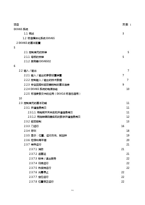
项目页数 1 EKM65系统1.1 概述 31.2 标准模块化系统EKM652 EKM65的基本配置52.1 控制单元的安装 52.1.1 母板的安装 52.1.2 服务器EKM650262.2 输入/输出72.2.1 输入/输出的参数设置装置72.2.2 控制输入/输出的技术数据72.2.3 安全回路和驱动器控制的基本连接92.2.4 EKM65系统的电源供给102.2.5 标准参数文件的应用(EKM16标准也适用)102.3 控制单元的基本功能112.3.1 井道信息拷贝112.3.1.1 用电磁开关来实现井道信息拷贝112.3.1.2 用旋转编码器实现的数字井道信息拷贝122.3.2 驱动控制132.3.3 门运行162.3.4 呼叫182.3.5 显示:位置、运行方向、到站钟192.3.6 检修和再平层202.3.7 特殊运行212.3.7.1 消防212.3.7.2 返基站212.3.7.3 锁梯/退出服务222.3.7.4 归底运行222.3.7.5 热保持运行222.3.7.6 光幕停止222.3.7.7 定位运行222.3.7.8 位置修正运行222.3.8 特殊呼叫控制(也对可测量的负载)2.3.9驱动的热测试3分散的部件243.1 通用输入/输出模块6508243.2 智能终端253.3 井道配线253.4 串联轿厢配线264 群控274.1 厅选的组织274.2 群控逻辑284.3 特殊群控功能295 运行显示及故障诊断305.1 运行显示305.2 故障诊断315.2.1 在服务模块中的故障诊断31 附:EKM65控制系统的功能说明BEIJING LAIYIN KELA Lift Machinery & Equipment Ltd.1 系统EKM651.1 概述EKM65是一个集成模块化的电梯专用控制系统,是由几个在两根总线系统上串行连接起来、功能化的模块组成的。
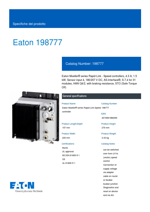
Eaton 198777Eaton Moeller® series Rapid Link - Speed controllers, 4.3 A, 1.5 kW, Sensor input 4, 180/207 V DC, AS-Interface®, S-7.4 for 31 modules, HAN Q4/2, with braking resistance, STO (Safe Torque Off)General specificationsEaton Moeller® series Rapid Link Speed controller1987774015081968350157 mm 270 mm 220 mm 3.43 kg RoHS UL approval IEC/EN 61800-5-1 CE UL 61800-5-1Product NameCatalog NumberEANProduct Length/Depth Product Height Product Width Product Weight Certifications Catalog Notes can be switched over from U/f to (vector) speed control Connection of supply voltage via adapter cable on round or flexible busbar junction Diagnostics and reset on device and via AS-RASP5-4401A31-4120110S1Diagnostics and reset on device and via AS-Interface Parameterization: drivesConnectParameterization: drivesConnect mobile (App) Parameterization: FieldbusParameterization: KeypadPC connectionBreaking resistanceIGBT inverterSelector switch (Positions: REV - OFF - FWD)Thermo-click with safe isolationControl unitKey switch position OFF/RESETPTC thermistor monitoringInternal DC linkKey switch position AUTOKey switch position HANDFour fixed speedsTwo sensor inputs through M12 sockets (max. 150 mA) for quick stop and interlocked manual operationBraking resistanceBrake chopper with braking resistance for dynamic braking4-quadrant operation possibleFor actuation of motors with mechanical brakeSTO (Safe Torque Off)IP65NEMA 121st and 2nd environments (according to EN 61800-3)IIISpeed controllerASIAS-Interface profile cable: S-7.4 for 31 modulesC1: for conducted emissions onlyC2, C3: depending on the motor cable length, the connected load, and ambient conditions. External radio interference suppression filters (optional) may be necessary.2000 VPhase-earthed AC supply systems are not permitted.AC voltageCenter-point earthed star network (TN-S network)Vertical15 g, Mechanical, According to IEC/EN 60068-2-27, 11 ms, Half-sinusoidal shock 11 ms, 1000 shocks per shaftResistance: 57 Hz, Amplitude transition frequency on accelerationResistance: 6 Hz, Amplitude 0.15 mmResistance: 10 - 150 Hz, Oscillation frequencyResistance: According to IEC/EN 60068-2-6Model CodeFeatures Fitted with:FunctionsDegree of protectionElectromagnetic compatibilityOvervoltage categoryProduct categoryProtocolRadio interference classRated impulse withstand voltage (Uimp)System configuration typeMounting positionShock resistanceVibrationInterfaceFour fixedspeedsintegrated PTCthermistormonitoring andThermoclick withsafe isolationoptional: 4sensor inputswith M12-Yadapter forswitchover tocreep speedoptional: Fasterstop if external24 V failsTwo sensorinputs throughM12 sockets(max. 150 mA)for quick stopand interlockedmanualoperationwith AUTO -OFF/RESET -HAND keyswitcheswith selectorswitch REV -OFF - FWDAbove 1000 m with 1 % performance reduction per 100 m Max. 2000 m-10 °C40 °C-40 °C70 °CIn accordance with IEC/EN 50178< 95 %, no condensation Adjustable, motor, main circuit0.4 - 4.3 A, motor, main circuit< 10 ms, On-delay< 10 ms, Off-delay98 % (η)4.1 A3.5 mA120 %Maximum of one time every 60 seconds 380 V480 V380 - 480 V (-10 %/+10 %, at 50/60 Hz)U/f controlPM and LSPM motorsBLDC motorsSensorless vector control (SLV) Synchronous reluctance motors0 Hz500 HzFor 60 s every 600 sAt 40 °C6.5 AAltitudeAmbient operating temperature - min Ambient operating temperature - max Ambient storage temperature - min Ambient storage temperature - max Climatic proofing Current limitationDelay timeEfficiencyInput current ILN at 150% overload Leakage current at ground IPE - max Mains current distortionMains switch-on frequencyMains voltage - minMains voltage - maxMains voltage toleranceOperating modeOutput frequency - minOutput frequency - maxOverload currentOverload current IL at 150% overload45 Hz66 Hz1.5 kW480 V AC, 3-phase 400 V AC, 3-phase 0.1 Hz (Frequency resolution, setpoint value)200 %, IH, max. starting current (High Overload), For 2 seconds every 20 seconds, Power section 50/60 Hz8 kHz, 4 - 32 kHz adjustable, fPWM, Power section, Main circuit Phase-earthed AC supply systems are not permitted. AC voltageCenter-point earthed star network (TN-S network)2 HP≤ 0.6 A (max. 6 A for 120 ms), Actuator for external motor brake Adjustable to 100 % (I/Ie), DC - Main circuit ≤ 30 % (I/Ie)280/207 V DC -15 % / +10 %, Actuator for external motor brake 765 VDC10 kAType 1 coordination via the power bus' feeder unit, Main circuit24 V DC (-15 %/+20 %, external via AS-Interface® plug) 180/207 V DC (external brake 50/60 Hz)AS-Interface Plug type: HAN Q4/2Max. total power consumption from AS-Interface® power supply unit (30 V): 190 mASpecification: S-7.4 (AS-Interface®)Number of slave addresses: 31 (AS-Interface®)Rated frequency - min Rated frequency - max Rated operational power at 380/400 V, 50 Hz, 3-phase Rated operational voltage ResolutionStarting current - maxSupply frequency Switching frequencySystem configuration typeAssigned motor power at 460/480 V, 60 Hz, 3-phase Braking currentBraking torqueBraking voltageSwitch-on threshold for the braking transistor Rated conditional short-circuit current (Iq)Short-circuit protection (external output circuits)Rated control voltage (Uc)Communication interface ConnectionInterfacesC3 ≤ 25 m, maximum motor cable length C1 ≤ 1 m, maximum motor cable length C2 ≤ 5 m, maximum motor cable length Meets the product standard's requirements.Meets the product standard's requirements.Meets the product standard's requirements.Meets the product standard's requirements.Meets the product standard's requirements.Does not apply, since the entire switchgear needs to be evaluated.Does not apply, since the entire switchgear needs to be evaluated.Meets the product standard's requirements.Does not apply, since the entire switchgear needs to be evaluated.Meets the product standard's requirements.Does not apply, since the entire switchgear needs to be evaluated.Does not apply, since the entire switchgear needs to be evaluated.Is the panel builder's responsibility.Is the panel builder's responsibility.Is the panel builder's responsibility.Is the panel builder's responsibility.Cable length10.2.2 Corrosion resistance10.2.3.1 Verification of thermal stability of enclosures10.2.3.2 Verification of resistance of insulating materials tonormal heat10.2.3.3 Resist. of insul. mat. to abnormal heat/fire by internalelect. effects10.2.4 Resistance to ultra-violet (UV) radiation10.2.5 Lifting10.2.6 Mechanical impact10.2.7 Inscriptions10.3 Degree of protection of assemblies10.4 Clearances and creepage distances10.5 Protection against electric shock10.6 Incorporation of switching devices and components10.7 Internal electrical circuits and connections10.8 Connections for external conductors10.9.2 Power-frequency electric strength10.9.3 Impulse withstand voltageIs the panel builder's responsibility.The panel builder is responsible for the temperature rise calculation. Eaton will provide heat dissipation data for the devices.Is the panel builder's responsibility. The specifications for the switchgear must be observed.Is the panel builder's responsibility. The specifications for the switchgear must be observed.The device meets the requirements, provided the information in the instruction leaflet (IL) is observed.Rapid Link 5 - brochureDA-SW-Driver DX-CBL-PC-3M0DA-SW-drivesConnect - installation helpDA-SW-USB Driver PC Cable DX-CBL-PC-1M5DA-SW-drivesConnectDA-SW-USB Driver DX-COM-STICK3-KITDA-SW-drivesConnect - InstallationshilfeMaterial handling applications - airports, warehouses and intra-logisticseaton-bus-adapter-rapidlink-speed-controller-dimensions.epseaton-bus-adapter-rapidlink-speed-controller-dimensions-002.eps eaton-bus-adapter-rapidlink-speed-controller-dimensions-004.eps eaton-bus-adapter-rapidlink-speed-controller-dimensions-003.epsETN.RASP5-4401A31-4120110S1.edzIL034085ZUrasp5_v25.stpramo5_v25.dwgGeneration change from RA-SP to RASP 4.0Generation change RAMO4 to RAMO5Generation change from RA-MO to RAMO 4.0Configuration to Rockwell PLC for Rapid LinkGeneration Change RA-SP to RASP5Generation Change RASP4 to RASP5DA-DC-00004612.pdfDA-DC-00003964.pdfDA-DC-00004184.pdfDA-DC-00004613.pdf10.9.4 Testing of enclosures made of insulating material10.10 Temperature rise10.11 Short-circuit rating10.12 Electromagnetic compatibility 10.13 Mechanical function BrochureDisegnieCAD modelIstruzioni di installazione mCAD modelNote per l'applicazione Report di certificazioneEaton Corporation plc Eaton House30 Pembroke Road Dublin 4, Ireland © 2023 Eaton. Tutti i diritti riservati. Eaton is a registered trademark.All other trademarks areproperty of their respectiveowners./socialmedia。

项目页数 1 EKM65系统1.1 概述 31.2 标准模块化系统EKM652 EKM65的基本配置 52.1 控制单元的安装 52.1.1 母板的安装 52.1.2 服务器EKM6502 62.2 输入/输出 72.2.1 输入/输出的参数设置装置 72.2.2 控制输入/输出的技术数据 72.2.3 安全回路和驱动器控制的基本连接 92.2.4 EKM65系统的电源供给 102.2.5 标准参数文件的应用(EKM16标准也适用) 102.3 控制单元的基本功能 112.3.1 井道信息拷贝 112.3.1.1 用电磁开关来实现井道信息拷贝 112.3.1.2 用旋转编码器实现的数字井道信息拷贝 122.3.2 驱动控制 132.3.3 门运行162.3.4 呼叫 182.3.5 显示:位置、运行方向、到站钟 192.3.6 检修和再平层 202.3.7 特殊运行 212.3.7.1 消防212.3.7.2 返基站 212.3.7.3 锁梯/退出服务 222.3.7.4 归底运行 222.3.7.5 热保持运行 222.3.7.6 光幕停止222.3.7.7 定位运行222.3.7.8 位置修正运行 222.3.8 特殊呼叫控制(也对可测量的负载)2.3.9驱动的热测试3分散的部件 243.1 通用输入/输出模块6508 243.2 智能终端 253.3 井道配线 253.4 串联轿厢配线 264 群控 274.1 厅选的组织 274.2 群控逻辑 284.3 特殊群控功能 295 运行显示及故障诊断 305.1 运行显示 305.2 故障诊断 315.2.1 在服务模块中的故障诊断 31 附: EKM65控制系统的功能说明1 系统EKM651.1 概述EKM65是一个集成模块化的电梯专用控制系统,是由几个在两根总线系统上串行连接起来、功能化的模块组成的。
母板EKM65(控制单元)用于中央数据的储存及处理。
永磁同步无齿轮曳引机MCK系列使用说明书请将此说明书交至最终用户(安装、使用、维护、保养等)手中并请妥善保存。
V201910前言非常感谢您选用本公司产品,我们将竭诚为您提供优质服务。
本司永磁同步无齿轮曳引机(以下简称曳引机)采用了先进的设计理念和制造工艺,产品具有结构紧凑、体积小、重量轻、能耗低、噪声小、效率高等特点。
本司曳引机设计、生产符合《GB7588-2003-电梯制造与安装安全规范》、《EN81-1:1998-电梯建造和安装的安全规则》、《GB/T24478-2009-电梯曳引机》中的各项有关规定。
本使用说明书叙述了正确使用本曳引机的方法,本说明书中的图示为代表性事例,与实际产品可能会有所不同。
一般注意事项1.本说明书因产品改进、规格变更及为了使说明书本身使用方便,会有适当的改动,本司保留对说明书的修改权利,内容如有变更,恕不另行通知。
2.开箱后请确认产品是否和订单的型号、规格一致。
误使用了不同的产品可能使电梯或曳引机等破损、人员伤亡的危险。
3.请根据产品铭牌上注明的重量和手册中规定的吊装方法仔细核实吊具的额定载重,吊具载重量不足时有产品坠落、翻到和人员伤亡的危险。
4.如遇资料损坏、遗失、产品铭牌字迹模糊破损时,请按封底上联系方式向本司订购。
警告:安全说明①安装、使用、维护及保养前,请认真阅读本说明书及相关附属资料,以免造成设备损坏,引起人员伤亡。
②安装、使用、维护及保养过程中,请严格按照本说明书规程操作,以确保设备正常及人身安全。
③本说明书中所示的图解为了说明细节部分,有将外壳或为了安全的遮盖物去除状态下描述的,本产品在运行前,务必按规定将外壳或遮盖物复原后按使用说明书操作运行。
④非专业人员严禁操作。
通用安全注意事项打上安全符号的段落、语句叙述了重要的内容请一定要遵守,错误使用时可能导致人身伤害和设备损害,错误使用严重时可能会导致人身伤亡!搬运、安装、接线、运行、操作、检查、维护、保养请由具备专业人员来进行。
如果客户将本司产品用于非设计要求或用途的场合,本司不承担责任。
如果客户对本司产品进行改造,则不在本司的保修范围内,本司亦不承担责任。
•包装箱适用于铲车、叉车搬运,搬运时必须按其重量尺寸选用合适的装卸设备。
•包装箱搬运时请注意掉落、翻倒、撞击,需要叠放时务必不能超过包装箱所示的叠放高度。
•收到产品后,应先检查产品的外观状况,如有破损,请及时与本司联系。
•收到产品后,请确认是否与订购的产品相同,如有不同,请及时与本司联系。
•除去包装箱后,要采取必要的防尘、防雨、防潮等防护措施。
•曳引机起吊前请确认曳引机重量,起吊时请使用本体吊环或吊孔,务必垂直起吊。
•曳引机搬运时请注意掉落、翻倒、撞击,已安装到机架上时不可全体起吊。
•请不要在含有爆炸性、烟雾、粉尘的空气中使用,曳引机周围不要放置障碍物和可燃物。
•有水滴油污滴落的场合严禁安装使用,特别注意不要让水滴油污附着在制动轮或曳引轮绳槽上。
•请不要取下曳引机上的铭牌、标牌、警示牌,请按规定和要求安装曳引机和附属件。
•请不要徒手碰触曳引机尖锐部位,请不要将手指或物品放入曳引机敞开部位。
•调试使用前,应测量曳引机定子和制动器的绝缘电阻,其值不低于0.5MΩ,测量时严禁触摸端子。
•电气操作,请确保曳引机和整套设备及附加或辅助电路绝缘良好。
•接线时请按电气规范进行,请不要从商用电源直接接线,请不要与专用控制柜以外的控制柜接线。
•有接地标识或要求的,请务必可靠接地。
•机械连接前,请务必确认曳引机旋转方向。
•请不要坐在或靠在曳引机上,运转中绝对不能接近或接触旋转部件。
•运行中曳引机和制动器表面温度很高,请不要用手触摸或身体接触。
•制动器调整、更换、失效时,请务必采取防止轿箱和对重脱落的有效防范措施。
•维修保养前,必须先停止整个电梯系统的运行,确保曳引机未被使用。
•轴承润滑脂注入、排出时按照要求进行,请注意旋转部件。
•长期存放使用前,先按以上规定检测,再低速(<20rpm)正反方向运转电机,使轴承均匀润滑。
目录1. 产品介绍 (1)1.1 结构原理 (1)1.2 规格参数 (1)1.3 工作条件 (1)2. 安装接线 (2)2.1 曳引机安装 (2)2.2 主回路接线 (2)2.3 制动器接线 (2)2.4 编码器接线 (3)2.5 盘车开关接线 (3)2.6 手动松闸安装 (3)3. 调试运转 (4)3.1 调试 (4)3.2 运转 (4)4. 维护保养 (5)4.1 维护保养检查表 (5)4.2 轴承润滑脂补给 (5)5. 故障诊断 (6)6. 紧急救援 (8)7. 附录 (9)7.1 块式制动器调整 (9)7.2 无机房远程松闸 (11)7.3 编码器更换安装 (13)7.4 编码器线接线图 (14)1. 产品介绍1.1 结构原理•曳引机由永磁同步电动机、曳引轮及制动系统等组成。
•曳引机采用高性能永磁材料和特殊的电机结构,具有低转速、大转矩特性。
•MCK系列为外转子结构,制动系统为块式制动器结构,曳引轮与制动轮同轴固定联接,并直接安装在电动机的轴伸端。
•制动器上装有微动开关用于监测制动情况,当制动器打开时,微动开关的常开触点闭合。
•曳引机工作原理:电动机由轴伸端的曳引轮输出扭矩,通过曳引轮和钢丝绳的摩擦来带动电梯轿厢运行。
当电梯停止运行时则由常闭制动器通过制动闸瓦制动,从而在曳引机失电状态下仍保持轿厢静止不动。
•MCK系列用于有机房,也可用于无机房。
•本司的每台曳引机出厂前都通过严格的品质检验,从而保证产品的质量和性能。
1.2 规格参数1.3 工作条件•海拔高度不超过1000m。
•室内使用, 环境空气不含有腐蚀性和易燃气体。
•环境温度应保持在0-40℃之间。
•环境相对湿度月平均值最高不大于90%。
同时该月月平均最低温度不高于25℃。
•曳引钢丝绳直径≤曳引轮直径四十分之一,表面不得涂润滑剂与其它杂物。
•曳引机必须由控制柜供电并且闭环控制,其额定参数以曳引机铭牌为准。
•控制柜电源的供电电压波动与额定值偏差不超过±7%。
2. 安装接线2.1 曳引机安装2.2 主回路接线接线盒内接线包括三相动力线(U 、V 、W ),接地线以及热敏电阻接线。
动力线连接在端子排上,接地线连接在接地端子上,热敏电阻接线采用压线帽连接方式。
2.3 制动器接线制动器线圈的额定电压为DC110V 。
两侧制动器各带有1个微动开关,微动开关有常开/常闭两副触点可供接线。
标准配置为常闭,即当微动开关触点闭合时表明该侧制动器也关闭。
吊装示意图注意•安装曳引机前,必须保证安装用机架、地基的强度。
•曳引机在起吊时请使用曳引机本体上的吊环或吊孔。
•起吊时务必垂直起吊,两吊勾之间的夹角必须小于90°。
•曳引机安装平面要保证水平,而且要有相应的减振措施。
•所挂钢丝绳及相应的载重应垂直通过曳引轮的中心平面。
•确保安装曳引机的机架表面平整,最大允许偏差为0.1mm 。
•有机房用盘车手轮在主机背面左下方,请注意机架干涉。
•固定曳引机的螺栓尺寸配底脚孔,用强度为8.8级螺栓。
•通常曳引机配有防跳杆和防护罩,安装钢丝绳后请复位。
主回路接线图注意•不可从商用电源直接接线。
•按左图所示与变频器接线。
•动力电缆应用带屏蔽电缆。
•连接电缆按电流合理选配。
•电缆屏幕层单端可靠接地。
•动力电缆与控制电缆分开。
•连接完检测有无断路短路。
注意•为保护曳引机异常情况过热烧毁, 请将热敏电阻接入热保护回路中。
热敏电阻常温时阻值不大于1Ω, 达到140℃时,阻值无穷大。
注意•为防止曳引机带闸运行或制动器出现异常情况, 请将制动器微动开关接入检测回路,两侧并联。
微动开关接线图2.4 编码器接线2.5 盘车开关接线2.6 手动松闸安装注意•本司曳引机必须由专用变频器供电,并且必须工作在闭环控制的方式下,因此需安装位置反馈装置(编码器)。
•针对不同变频器控制方式不尽相同,要求编码器反馈信号也不相同,本司备有与之对应型式的编码器以供客户选择。
•编码器的详细参数以及接线定义可详见编码器说明书。
•编码器末端引出线接入出线盒,出线方式为航空插头。
•为便于客户方接线,本司提供7m 编码器延长屏蔽电缆。
•编码器延长线接变频器侧的式样可按客户方要求定制。
注意•编码器屏蔽线必须单端可靠接地。
注意 •机械手动松闸装置仅在电梯发生故障和停电救援的情况下使用。
•请将手动松闸置于常人不易触及的地方,非紧急状况严禁使用。
注意•有机房用曳引机按标准规定,配有一盘车检测开关,有常开/常闭两副触点可供用户接线。
有机房松闸装置无机房远程松闸装置(详见附录7.2)•手动松闸分为有机房用和无机房用两种。
•有机房手动松闸将松闸手柄旋入后作用。
(见左图)•无机房远程松闸请按示图所示安装使用。
(见下图) 松闸方向 松闸方向3. 调试运转3.1 调试注意•曳引机的调试作业必须由专业的、受过培训的技术人员进行操作。
•调试时曳引机可能出现震动的现象,调试前请将曳引机可靠固定。
•为使曳引机能运行平稳,请按铭牌数据设置变频器并进行自学习。
•若用运转自学习功能,务必将钢丝绳脱开,制动器通电正常工作。
•编码器原点自学习至少三次,且自学习角度值偏差应在5度范围内。
3.2 运转•请先以低速(检修速度)正反转运行,确认系统是否正常工作。
•请以变速运行一定时间,同时监测运行电流是否在合理范围内。
•以额定梯速运行时,轿厢舒适感调整可按变频器相应参数设置。
4. 维护保养4.1 维护保养检查表维护保养请下表所示内容定期检查:4.2 轴承润滑脂补给本司轴承寿命设计已满足运行要求,曳引机运行一段时间后(1年或视需要)需添加润滑脂,密封轴承不必添加或更换润滑脂。
如需补给请按如下注入要求执行:生产日期为2018年前的主机请注入美孚润滑脂 XHP222(NLGI 2级),生产日期为2018年后的主机请注入壳牌润滑脂 壳牌佳度S3(V220C 2级) •MCK100/ /MCK300注油方法•MCK200/ /MCK500注油方法注意•轴承润滑脂的补给请注意电机的旋转部件,补给时电梯务必在停止状态。
•补给时请注入同品牌同规格的润滑脂,如果不同的润滑脂混合使用,会缩短润滑脂的使用寿命。
•补给时如有出油封盖,注油时请取下,补给后请复位。
•补给时请用专用润滑脂补给枪并缓慢注入,过急补给会使润滑脂沿轴承面漏出。
•补给后曳引机运行会有短时轴承温度上升现象,经一定时间还原,请不用担心轴承温度的上升。
注油/排油•补给位置在曳引轮中心。
•注油前请取下封口螺钉。
•掏去注油/排油口处残油。
•缓慢注入10-20g 润滑脂。
•注完后请将该螺钉复位。
•补给位置在曳引轮正面。
•注油前请取下排油口螺钉。
注油口5. 故障诊断注意•曳引机故障诊断处理必须由专业的、受过培训的技术人员进行操作。