CSC200系列装置调试软件使用说明
- 格式:pdf
- 大小:419.31 KB
- 文档页数:13


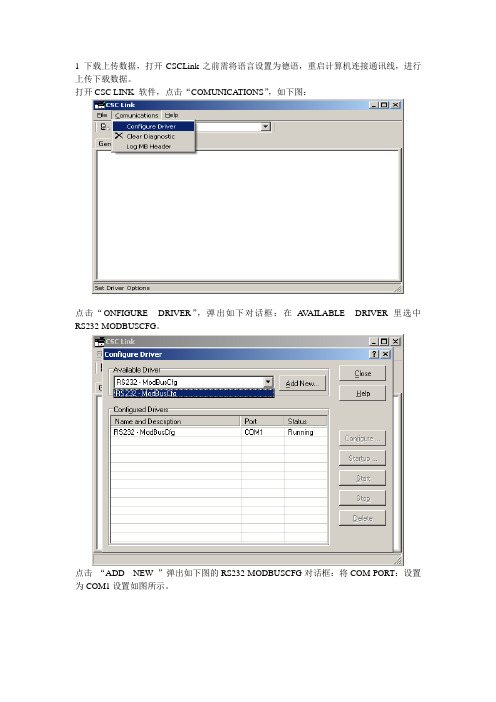
1 下载上传数据,打开CSCLink之前需将语言设置为德语,重启计算机连接通讯线,进行上传下载数据。
打开CSC LINK 软件,点击“COMUNICA TIONS”,如下图:
点击“ONFIGURE DRIVER”,弹出如下对话框:在A V AILABLE DRIVER里选中RS232-MODBUSCFG。
点击“ADD NEW ”弹出如下图的RS232-MODBUSCFG对话框:将COM PORT:设置为COM1设置如图所示。
“OK ”确定。
然后将下图端口选成“RS232-MODBUSCFG COM1”。
打到“GENERAL”看是否有数值传送(数值是否变化)。
将“CSC LINK”最小化,打开CSC TOOL,将DRIVER路径选成“RS232-MODBUSCFG COM1”。
打开程序后“GO ONLINE”,入图。
下载程序,如下图:
完成后关闭“TOOL”软件,到“程序”-“附件”-“通讯”-建立一个“超级终端”。
5. CTRL-A联机,7-4-2进入到CAN总线组态建立网络连接。
如下图:变频器CAN NODE 设置为02,柜内和机旁W AGO分别设置为05和08。
c)网络连接检查7-4-2 回车进入
正常全部连接状态
正常未连接状态
不正常状态。

CSC系统调试说明书PFISTER GmbH1.1.2 键的功能 (VT100)移动光标或选择参数输入数据时设置光标的位置回车键,用于输入或激活选择或接收数据输入数字或直接选择菜单输入十六进制的数 显示主菜单 刷新当前菜单,并切换到VT100 方式 刷新当前菜单,并切换到PHT 方式 错误确认 功能或指令中止 功能或指令执行 调用“服务联机”菜单(仅限于 CSC MASTER )1.1.3 PHT (PFISTER 手操器)的联机1.) 把PHT 联到CSC 的服务接口X17 插头上。
2.) 设备的标识符和版本号在PHT 的 1--3 行显示。
在第四行将显示“Ctrl Y > Connect”,这时PHT 已经准备就绪。
3.) 按“Ctrl Y ”键,PHT 与CSC 的联接就建立了。
4.) 按“Ctrl A” 键,显示主菜单。
下面数据将显示在PHT 上。
第一行 ->菜单字头第二行 ->参数说明第三行 ->技术值或参数设定第四行 ->错误信息(如果存在)如果有问题,检查与CSC 的联接和设置(波特率,数据格式)1.1.4 手操器 PHT 的按键功能描述F1 的题字和功能 传送PHT 的标识符 F2的题字和功能 执行 F3的题字和功能错误确认F4的题字和功能转到主菜单F5的题字和功能放弃 F6的题字和功能 提出用于输入字母和特殊字符的表格或在通电后进行组态滚动选择菜单或在选择参数时选择菜单 回车键,用于输入,接收或激活选择 设置光标的位置(输入的位置) 输入十进制数据或直接选择菜单1.2 操作及其显示的注解用 Ctrl + A 键可以从任何菜单返回主菜单。
回到上一级菜单用“0”键或把光标定位在<<Exit(0) 并按回车键。
任何输入和选择都用回车键来取舍。
每个选项会在左侧用“<….”来标记。
用键来选择。
任何一个输入和选择都可用“Ctrl + C ” 放弃,原设置保持不变。
CSI-200E测控装置管理软件使用说明书CSI-200E测控装置管理软件使用说明书编制:赵云校核:肖彬审核:邓俊波版本记录目录1概述 (1)1.1适用范围 (1)1.2硬件配置、操作系统及软件安装 (1)1.3主要功能特点 (1)2绘制间隔主接线图 (3)2.1新建及保存文件 (3)2.2元件绘制 (4)2.3主接线图下传 (7)2.4保存主接线图为位图文件 (8)3可编程逻辑控制器 (8)3.1PLC的节点分类 (8)3.2操作类型分类 (9)3.3使用规则 (10)3.4可编程逻辑的编写 (10)3.5PLC下传、上传及校验 (21)3.6PLC编程技巧 (21)3.7用PLC实现遥控功能 (22)3.8用PLC实现同期功能 (23)3.9用PLC实现调压功能 (26)3.10用PLC实现间隔间五防闭锁 (27)3.11把PLC梯形图保存为位图 (29)4装置配置 (30)4.1装置设置 (30)4.2通道配置 (34)4.3其他配置 (37)4.4下传装置配置定值 (40)561850建模 (41)5.1建模配置 (41)5.2高级配置 (47)5.3导出模型 (48)6其他部分说明 (49)6.1下载程序 (49)6.2文件.CSI说明 (50)6.3串口配置及报文显示 (50)6.4界面英化 (51)1概述1.1适用范围CSI200EManage V4.13用于CSI-200E系列数字式综合测量控制装置(以下简称装置或间隔)PC端辅助管理软件,也可用于简单的串口通讯监视。
1.2硬件配置、操作系统及软件安装在装有Windows 2000/XP(或Windows的更高版本)系统都可以使用该软件。
软件只有一个文件,即软件本身,无需安装,也不需要其他控件或库的支持,直接运行便可。
由于软件配置的所有信息都是通过串口下传到装置的,所以要求计算机至少有一个RS-232-C串口或配置USB-RS232转接器。

四方公司CSC系列装置打印说明第一、公司目前使用的打印盒种类1、CSN-010A 打印机接口,是LON网打印接口盒,软件通用版本是V3.31;是通过LONWORKS现场总线来传输打印信息的。
一个打印盒,可以接多台装置进行同时打印。
对于新品Master版本为高压定制版本3.0xD(3.04D—3.10D系列版本)必须使用定制版本V3.31D配合打印。
注意事项:1)、CSN-010A打印机接口的软件版本,从V3.30开始,必须和MASTER上的NEURON3120芯片的V1.00N软件版本配合一起使用。
否则会出现录波打印不正确的问题。
V3.30以下的版本,必须和MASTER上的NEURON3120芯片的V1.00软件版本配合一起使用。
2)、如果打印接口的指示灯常亮,表示打印盒已经损坏,需要更换。
3)、如果要结束本次打印,先按下装置“QUIT”键,然后关闭打印机。
2、CSN-4打印机接口,是串口打印盒,通用版本是V1.02。
是通过接CSC系列新平台保护装置(装置的管理板为087、125型号)的打印收、打印发、打印地三根线来进行打印的。
最多可以接四台CSC保护装置同时进行打印。
注意事项:1)、此打印盒电源必须为交流,电压范围220V ±10%。
2)、目前此打印盒只支持串口打印,不支持LON网打印,所以端子的LON-A, LON-B两端口请保持为空,不接线,以免引起干扰。
3)、打印盒上电后,此时面板上的绿灯会闪一下,这是正常情况,如果上电后,绿灯常亮,表示打印盒已经损坏。
4)、打印盒不支持管理板(MASTER)的485口的A、B端子进行打印。
5)、如果要结束本次打印,先按下装置“QUIT”键,然后关闭CSN-4的电源3、CSC系列新平台保护装置(装置的管理板为087、125型号),通过串口打印线,直接连接打印机,进行打印。
注意事项:1)、一定要:“先接好打印串口线,然后再给打印机上电”!2)、如果打印不能进行,打印进度停止不动,滞留在“%”进度上。


低压保护问题处理手册(CSC-200篇)CSC200系列保护装置适用于110kV以下电网输配电系统和发电厂6KV厂用电系统的保护测控一体化产品。
全系列装置采用全封闭后插式结构,装置机箱高度为4U宽度为19/2英寸,32 位微处理器和14位数据采集(A/D); 支持故障录波功能;可提供LONWORKS、RS485、PROFIBUS-DP现场总线及光电以太网通讯接口;支持网络对时和GPS脉冲对时,支持IRIG-B 码对时;支持4~20mA模拟量直流输出;支持开入开出硬件扩展(DIO插件);测量电压电流表计精度为0.2级,功率和电度0.5级;电厂版本CSC200系列装置软硬件略区别于电网版装置,其硬件项目号为BD2008015,软件项目号为BD2009005;支持交流控电场合的应用需求。
目前新建发电厂厂用电6KV微机保护装置标准配置方案使用电厂版本CSC200系列装置。
因产品发展过程和历史因素综合作用影响,个别发电厂厂用电系统也在使用电网标准版CSC200系列装置。
电网标准版CSC200系列装置也有针对交流控电应用场合的定制硬件产品,硬件项目号为CD2007001。
下面针对电厂版本与电网标准版间的软硬件差异、CSC200系列装置在发电厂厂用电应用场合使用调试中出现的一些问题进行介绍。
一、电厂版本与电网标准版CSC200系列装置间的差异1.装置系列包含的子型号差异1.1电网标准版CSC200系列装置型号电厂厂用电系统常用型号装置:CSC-211数字式线路保护测控装置CSC-236数字式电动机差动保护装置(10kV及以下异步电动机)CSC-237A数字式电动机综合保护测控装置(10kV及以下异步电动机)CSC-237C数字式电动机主备一体保护测控装置(10kV及以下异步电动机)CSC-241C数字式厂(所)用变保护测控装CSC-241G数字式变压器主备一体保护测控装置CSC-326GC数字式变压器差动保护装置(66kV及以下电压等级)CSC-298数字式PT保护测控装置CSC-246数字式备用电源自动投入装置CSC-231数字式电抗器保护测控装置(66kV电压等级)CSC-213光纤纵联差动保护测控装置(注:高压保护平台产品)电厂厂用电系统一般不使用的型号装置(常用于电网输配电变电站):CSC-212数字式线路距离保护测控装置CSC-215数字式母联保护测控装置CSC-221A数字式电容器保护测控装置(66kV电压等级不平衡电压保护)CSC-221B数字式电容器保护测控装置(66kV电压等级不平衡电流保护)CSC-237B数字式电动机综合保护测控装置(10kV及以下同步电动机)CSC-241B数字式变压器后备保护测控装置(66kV及以下电压等级)CSC-241E数字式接地变压器保护测控装置(66kV及以下电压等级)CSC-241F非电量保护装置1.2电厂版本CSC200系列装置型号CSC-211数字式线路保护测控装置CSC-236数字式电动机差动保护装置CSC-237A数字式电动机综合保护测控装置CSC-237C数字式电动机主备一体保护测控装置CSC-241C数字式厂(所)用变保护测控装CSC-241G数字式变压器主备一体保护测控装置CSC-326GC数字式变压器差动保护装置CSC-298数字式PT保护测控装置CSC-246数字式备用电源自动投入装置CSC-231数字式电抗器保护测控装置2.装置软件的差异我司研发体系默认将电网版CSC200系列装置程序视为通用标准版本,相对于此电厂版本CSC200系列装置软件程序被定义为定制版本,软件项目号为BD2009005。

微机保护调试软件EPPC使用说明编制:校核:审定:版本号:V1.0文件代号:出版日期:2005.041.软件介绍EPPC 微机保护调试软件是配合CSC200、CSC326G系列微机保护装置的工具软件,不但能够完成人机对话的功能,还能对保护录波数据进行分析。
EPPC微机保护调试软件,兼容Windows9X,Windows2000和WindowsXP操作系统,操作简单方便。
EPPC软件通过计算机的串行口和保护装置面板的串口连接。
该软件在应用时不影响保护的正常运行。
2.安装与卸载2.1 运行环境●操作系统:Windows95/98/2000/XP;●最低配置:CPU:80486DX/66以上;内存:8MB;显示卡:标准VGA,256色显示模式以上;硬盘安装:2M空间。
●建议配置:CPU:奔腾133或更高;内存:16MB;显示卡:标准SVGA,16k色以上显示模式。
2.2安装步骤●将EPPC.zip 释放到你所需要的文件夹下●运行install.bat 导入Microsoft ActiveX 控件●使用RS232 (2-3,3-2,5-5)串口连接计算机和装置图调试端口信号定义3.功能菜单本软件提供如下功能:3.1 监视面板:整定操作:整定值查询,修改,固化。
录波数据:故障录波数据查询,分析。
事故报告:保护动作事件及开关变位事件监视。
开入监视:开入量定时查询。
交流测试:交流测试及调校。
采样数据:实时采样数据监视。
内存单元:内存单元数据查询及修改。
保护配置:保护自描述信息浏览。
下图为监视面板的功能菜单:3.2 控制面板:定值切换:保护运行定值区切换。
压板设置:保护压板设置。
开出传动:开出传动测试。
时间设置:装置时间设置。
信号复归:装置信号复归。
标签设置:设置保护装置地址。
保护方案:保护方案升级/更新。
软件更新:保护程序升级/更新。
以下为控制面板的功能菜单:3.3 系统功能:运行模式:运行/调试模式切换。
调试模式:运行/调试模式切换。


CSC系统调试说明书CSC系统调试说明书PFISTER GMBH1.1.2 键的功能(VT100)移动光标或选择参数输入数据时设置光标的位置回车键,用于输入或激活选择或接收数据输入数字或直接选择菜单输入十六进制的数显示主菜单刷新当前菜单,并切换到VT100 方式刷新当前菜单,并切换到PHT 方式错误确认功能或指令中止功能或指令执行调用“服务联机”菜单(仅限于 CSC MASTER )1.1.3 PHT (PFISTER 手操器)的联机1.) 把PHT联到CSC 的服务接口X17 插头上。
2.) 设备的标识符和版本号在PHT 的 1--3 行显示。
在第四行将显示“Ctrl Y > Connect”,这时PHT已经准备就绪。
3.) 按“Ctrl Y ”键,PHT 与CSC 的联接就建立了。
4.) 按“Ctrl A” 键,显示主菜单。
下面数据将显示在PHT 上。
第一行 ->菜单字头第二行 ->参数说明第三行 ->技术值或参数设定第四行 ->错误信息(如果存在)如果有问题,检查与CSC的联接和设置(波特率,数据格式)1.1.4 手操器 PHT 的按键功能描述F1 的题字和功能传送PHT 的标识符 F2的题字和功能执行 F3的题字和功能错误确认F4的题字和功能转到主菜单F5的题字和功能放弃F6的题字和功能提出用于输入字母和特殊字符的表格或在通电后进行组态滚动选择菜单或在选择参数时选择菜单回车键,用于输入,接收或激活选择设置光标的位置(输入的位置)输入十进制数据或直接选择菜单1.2 操作及其显示的注解用 Ctrl + A 键可以从任何菜单返回主菜单。
回到上一级菜单用“0”键或把光标定位在<<="">按回车键。
任何输入和选择都用回车键来取舍。
每个选项会在左侧用“<….”来标记。
用键来选择。
任何一个输入和选择都可用“Ctrl + C ” 放弃,原设置保持不变。

版本:V7.0CSC-200/CSC-326G说明编号:C51182项目编号: BT2009027项目类别:☐软件☐硬件☑软硬件归档类别:☑通用☐定制是否有配套使用的工程说明书☑否☐是说明书编号版本:是否有配套使用的定值清单☑否☐是是否有关联定制软硬件☑否☐是具体描述:原理图是否有变化☑否☐是具体描述:是否有新增物料☑否☐是新增物料为:___________________是否需设计新的自动测试软件☑否☐是☐不涉及项目综述版本升级说明内容一软件说明1系统软件修改说明:对CSC-200程序进行升级,系统程序功能改动如下:✧解决LON网异常、LON网召录波丢报文、以太网不通等问题。
✧完善4-20mA功能,软件支持新、旧AO插件;扩大20mA可调校范围,以适应新AO板为保证4mA的输出精度对硬件做的调整,防止调校不到要求值;20mA输出适应保护CT1A或5A,自动调整输出范围。
✧完善录波存储方式,只有启动的事件录波和带保护动作的事件录波分区存放,防止多次启动导致动作录波被覆盖。
✧降低测量电流门槛值为15mA,解决测量数据不刷新的问题。
✧增加DIO功能。
✧检修状态投入,61850后台可以允许上传操作,如响应通用分类服务的总查询,能够执行通用总召,回答总召唤,也能响应录波召唤,但是禁止下发命令,以和高压做法统一。
✧检修状态投入,2000规约仍能上送3007报文,仅反映检修状态的实际位置,以防止通讯中断。
按照2000规约实施细则,3007报文改两帧上送。
✧支持自动上送2000规约模版。
✧优化103遥测突变的判断。
✧优化103规约的遥信虚拟对点操作,遥信对点菜单返回,进行过操作的信号点将上送当前实际状态。
✧进行相关菜单的优化,某种功能退出,其相应的菜单不允许操作。
✧增加无值调整刻度的功能,以适应不得已情况下,无标准源,装置能够有正常显示。
✧降低测量PT和CT的变比上限值为2和7,以适应低压产品的实际应用场合。

TRE / Paula / 06.10.2000889.920.20.14 BA GBOPERATOR'S MANUALCSC CAN-System-Controller Operating devices889.920.20.14 BA GBThis documentation is valid for:Software:899.920.20.0ZFrom Version: 3.0Created under:WinWord 97Template:DOK_GRD.dotTRE / Paula / 06.10.2000889.920.20.14 BA GBContents Page 1GENERAL (3)1 .1Symbolic notation (4)1 .2Safety notes (5)1 .3Menu representation (6)1 .3.1Terminal types supported (6)1 .3.2View of the CSC M AIN MENU in VT100 mode with the Windows95 Hyperterminal (6)1 .3.3View of the CSC M AIN MENU in PHT mode with the Pfister Hand Terminal (7)1 .4Service interface (8)1 .4.1Setting the service interface: (9)1 .4.2Connections, connecting cables (9)2HYPERTERMINAL (VT100 MODE) (10)2 .1Hyperterminal settings (10)2 .2Hyperterminal key assignments (11)2 .3Hyperterminal screen format (VT100 mode) (12)2 .4Hyperterminal connection setup (12)2 .5Connection setup from the C-Box or c-VOB module to the Hyperterminal (13)3PFISTER HAND TERMINAL (PHT) (14)3 .1Pfister Hand Terminal key assignments (14)3 .2Screen setup on the Pfister Hand Terminal (PHT Mode) (14)3 .3Pfister Hand Terminals settings (15)3 .4Connection setup with the Pfister Hand Terminal (16)3 .5Connection setup from the C-Box or c-VOB module to the PHT (16)4CONNECTION SETUP (17)5MENU OPERATION (18)5 .1General operating remarks (18)5 .2Parameter entry and change (18)5 .2.1Selection fields and lists (<................t/h). (19)5 .2.2Entry fields ( 000.00 kg/h) (19)6EXAMPLES (20)6 .1Changing a selection field (20)6 .2Changing an entry field (22)7INDEX HISTORY (23)Copying of this document, and giving it to others and the use or communication of the contents thereof, areforbidden without express authority.© PFISTER GmbH, Augsburg 1998TRE / Paula / 06.10.2000889.920.20.14 BA GB 1 GENERALThe purpose of this documentation is to show the reader the operating and connection possibilities for the Pfister CSC (CAN System Controller) Feeding Control.The operation of the CSC CAN System Controller is comprised of the following actions:♦display the actual value during operation♦display the parameters during operation♦change the monitoring parameters such as limits and monitoring times during operation♦change SPS and variable programming during the operation♦change scale parameters when the scale is stopped♦adjust the scaleOperation in the sense of control and monitoring of an automatic operation is not contained in this document. This documentation is intended for the technical support personnel who carry out the monitoring adjustment and troubleshooting for the feeding and weighing system.TRE / Paula / 06.10.2000889.920.20.14 BA GB1 .1SYMBOLIC NOTATIONSafety notes (see Chapter 1.2)Remarks, notes, additional informationS MALL CAPITALS (BOLD )CSC parameterAction to carry out on the LOCALscaleAction on PCKey representation for PC / Laptop+Key combination on PC / LaptopStep 1: Action on Pfister Hand TerminalKey on Pfister Hand TerminalAbbreviations O outputFM Feeding Measurement CSC CAN System Controller CPI CAN Process Interface DBW Belt Weighfeeder DFM flow meterPCM pressure compensation DRW Rotor Weighfeeder DWdata wordI inputFBW Conveyor Belt Weigher CW Checkweigher M markerPHT Pfister Hand Terminal T timer VAR variable CTcounterTRE / Paula / 06.10.2000889.920.20.14 BA GB1 .2 SAFETY NOTESThis document contains notes that you must observe for your personal safety, to protect the safety of third parties and to avoid material damage.The notes are stressed by a symbol and are portrayed according to the degree of danger as follows:Symbol MeaningATTENTIONThis symbol is in the documentation in places where special care is to betaken in order to prevent damage to or destruction of the device,components, or other system parts.ATTENTIONThis symbol distinguishes notes that give information whose disregardcould endanger the health, the ability of the devices/components to functionor the security of the data.WARNINGThis means that death, severe bodily injury or considerable materialdamage could occur if the corresponding precautions are not taken.Warning of a danger areaDIN4844 - W9 UVV / VBG125 Nr. W 09Commissioning and operation of the devices and changes to the set-up and parameters of the device may be carried out only by qualified personnel.In the notes in this document concerning safety regulations, qualified personnel are people who fulfill the following requirements:Authorization to commission, to ground and to identify devices, systems and electrical circuitsaccording to the safety technology standards.Training by an employee of the Pfister Company regarding commissioning, operation, maintenanceand service of the Pfister Load Systems.Authorization from the manager of the system or system part, as well as precise knowledgeconcerning the context and sequences in the processes involved.TRE / Paula / 06.10.2000889.920.20.14 BA GB1 .3 MENU REPRESENTATION 1 .3.1 Terminal types supportedThe CSC CAN System Controller supports two display modes.Pfister Hand Terminal PHTPHT mode4-line display / 16 places Terminal emulation program VT100 mode 25-line display / 80 places(e.g., Windows95 – Hyperterminal ; Norton Commander – Term95)Because it is widely circulated, the Hilgraeve Hyperterminal , which is delivered with Microsoft Windows95/98 , is used as the model for terminal programs.1 .3.2 View of the CSC M AIN MENU in VT100 mode with the Windows95 HyperterminalType size and style may differ according to the systemsettings of the terminal programTRE / Paula / 06.10.2000889.920.20.14 BA GB1 .3.3 View of the CSC M AIN MENUin PHT mode with the Pfister Hand TerminalExtract representation for betterreadabilityTRE / Paula / 06.10.2000889.920.20.14 BA GB1 .4 SERVICE INTERFACEThe CSC CAN System Controller can be connected to a terminal or a PC via the CSC connection X17 (in the switch cabinet) or via a CAN bus (supplied locally) with the CPI connection X10 on the C-box– module (BWF, BS, FM) orthe C-VOB module (RWF). Each connection is a 9-pin SUB-D connector.Abb.: CSCFig.: C-Box – Modul (Local)TRE / Paula / 06.10.2000889.920.20.14 BA GB1 .4.1 Setting the service interface:Baud rate= 9600 baudData format= 1 start bit; 8 data bits; 1 stop bit; no parity1 .4.2 Connections, connecting cablesThe connection to the CSC CAN System Controller (X17) and to the C-Box module or to the C-VOB module (X10) is implemented as a 9-pin SUB-D connector.The connection’s pin layout is compatible with a serial PC interface COMx – a commercially available serial null model cable can be used as the connecting cable.Attention! The Pfister Hand Terminal PHT is supplied with +12V on PIN 9. Before using a pre-manufactured cable, check if PIN 9 is connected and break this connection if necessary. Supplying external power over the serial PC interface can lead to malfunctions in some PCsystems!PCT(x) 2R(x) 3(Gnd) 5CAN SystemController3 (Rx)2 (Tx)5 (Gnd)9 (+12V)TRE / Paula / 06.10.2000889.920.20.14 BA GB 2 HYPERTERMINAL (VT100 MODE)2 .1 HYPERTERMINAL SETTINGSWindows Hyperterminal properties should be set as follows:Connection Direct connection over COM1 (or another free COM interface on PC/Laptop)Emulation VT100Configuration Baud rate= 9600 baudData format= 8 data bits; no parity, 1 stop bit; no protocolTRE / Paula / 06.10.2000889.920.20.14 BA GB 2 .2 HYPERTERMINAL KEY ASSIGNMENTSMove cursor to line of desired menu entryor select the desired setting in the case of parameter selection.Set the cursor position (input position) on entering data.“Return key“ for an input or activate selection or accept data...Input of decimal values or direct selection of a particular menu entry..Input of hex_values.+Display the main menu.+Refresh current menu and switchover to VT100 mode.+Refresh current menu and switchover to PHT mode.+Acknowledge error.+Function or command “Abort“.+Function or command …Execute“.+Invoke the “CONNECTION-SERV.“ menu (for CSC master onlyTRE / Paula / 06.10.2000889.920.20.14 BA GB2 .3 HYPERTERMINAL SCREEN FORMAT (VT100 MODE)2 .4 HYPERTERMINAL CONNECTION SETUPConnect the PC to the CSC CAN System Controller (Connection X17) and start the Hyperterminal. Pressing the key combination + causes the main menu to be initialized on the CSC.The following screen should be displayed.If only a 4 row display appears then the CSC is in PHT Mode and must be switched toVT100 Mode with the key combination +.M enu heading CSC node numberM enu num berOperating modeOperating notesErrormessageC ursor positTRE / Paula / 06.10.2000889.920.20.14 BA GB2 .5 CONNECTION SETUP FROM THE C-BOX OR C-VOB MODULE TO THE HYPERTERMINALConnect the PC to the service interface X10 on the C-Box module or the C-VOB module and initialize by pushing the keys +.Select point 3 CPI1 ->S ERVER with the cursorkeysand accept with thekey.Since the connection between the CSC and CPI runs over the CAN bus,changes to the CAN bus settings are NOT possible !TRE / Paula / 06.10.2000889.920.20.14 BA GB3 PFISTER HAND TERMINAL (PHT)3 .1 PFISTER HAND TERMINAL KEY ASSIGNMENTSSend PHT identifierExecuteAcknowledgeGoto main menuAbortCall up the table for entry of alpha- and special characters or activate the configuration after switching on.Step through menu entries, or selection …Return“ key for an input or table in the case of parameter selection.activate selection or accept.Set the cursor position ...Input of decimal values or direct (input position) for entries.selection of a menu entry.3 .2SCREEN SETUP ON THE PFISTER HAND TERMINAL (PHT MODE)TRE / Paula / 06.10.2000889.920.20.14 BA GB3 .3 PFISTER HAND TERMINALS SETTINGSThe display contrast and the RS232 interface settings can be changed on the PHT Pfister Hand Terminal.Connect the PHT Pfister Hand Terminal to the CSC CAN System Controller (Connection X17) on the C-Box module (X10) or on the C-VOB module (X10).Activate key and the PHT configuration menu K ONTRAST is called upUse the keys to adjust the display contrast from +8 ... – 8.Activate key to call up the PHT’s RS232 I NTERFACE configuration menuThe keys change the interface’s transmission speed.Possible settings are:2400; 4800; 9600; 19200 Baud (default setting: 9600)Activate the key and the menu point EXIT >> is displayed Press the key to return to the PHT initialization screen.All Pfister Hand Terminals are delivered already pre-configured in the factory; an adjustment of or change to the settings listed above isnormally not necessary.TRE / Paula / 06.10.2000889.920.20.14 BA GB3 .4 CONNECTION SETUP WITH THE PFISTER HAND TERMINALConnect the PHT Pfister Hand Terminal to theCSC CAN System Controller.Activate key – the connection to the CSC is made and the PHT mode is initialized.Activate key – the CSC main menu is displayed.3 .5CONNECTION SETUP FROM THE C-BOX OR C-VOB MODULE TO THE PHTConnect the Pfister Hand Terminal to the service interfaceX10 on the C-Box module or the C-VOB module.Activate key – the connection to the CPI is made and the PHT mode is initialized.Press cursor keyPress cursor keyPress the return keyActivate the connection to the CSC andinitialize the CSC M AIN MENUSince the connection between the CSC and CPI runs over the CAN bus, changesto the CAN bus settings are NOT possible!TRE / Paula / 06.10.2000889.920.20.14 BA GB4 CONNECTION SETUPTermination of the communication with the CSC CAN System Controller should be carried out as follows:1. Return to the CSC M AIN MENU by pushing (possibly several times) the key combination+Upon a connection interruption (unintentional or not), the CSC notes the current menu position and returns to this menu again when the connection is re-established.At the same time, the CSC doesn’t register the break in the connection, i.e., on one hand actions already started, e.g.acceptance of the rotation constants or determination of the zero value, are not influenced and are carried out in the normal way; on the other hand, display screens continue to be refreshed although a display device is no longer connected.§If one of the file editors, a monitor function or the CAN2 system bus should abort (only in theHyperterminal – VT100 mode), the key combination + must possibly be pressed several times or security queries for storing must be answered.§If the connection is over the C-Box module or the C-VOB module (locally), the service connection between the CSC and CPI should definitely be ended, since otherwise data which is no longer needed is constantly sent over the CAN BusThis additional data traffic does not lead to any feedrate loss in the data transmission on the bus connection, but is not necessary.Select point 9 S ERVER à EXIT in the CSC M AIN MENU to end the server connection and return to the Main menu CPI1 with thekey.2. Terminate connection between CSC and the Hyperterminal or PHTDisconnect the connecting cables; the PHT turns off without supply voltage, the Hyperterminal must be terminated.TRE / Paula / 06.10.2000889.920.20.14 BA GB5 MENU OPERATION5 .1 GENERAL OPERATING REMARKSThe key combination + causes a return to the main menu from all menus.Exceptions are the file editors (SPS, VAR, PRT), the monitor functions (I/O/FLG/DW/VAR/T/CT) and the CAN-system bus menus; here + causes the respective screen to be left with a return to the previous menu. Pushing the key or selecting the menu point << E XIT (0) always causes a return of one menu level.A menu selection is possible by direct entry of the menu number or by placing the cursor in the corresponding line and pushing the key.5 .2 PARAMETER ENTRY AND CHANGEHeaderSelection Entries SubmenuTRE / Paula / 06.10.2000889.920.20.14 BA GB5 .2.1 Selection fields and lists (<................t/h)Selection field dimension<....................t/h DimensionSelect the desired parameter line with the cursor keysand activate the selection field with the key. <....................t/h DimensionSelect the desired dimension with the cursor keysand accept the selection and leave the field with the key. Selection field X6 Interface Protocol <....................OFF ProtocolSelect the desired parameter line with the cursor keysand activate the selection field with the key. <....................OFF ProtocolSelect the desired protocol with the cursor keysand accept the selection and leave the field with the key.5 .2.2 Entry fields ( 000.00 kg/h)W1 0007,00 kg/h Local feedrateselect the desired parameter line with the cursor keysand activate the entry field with the key0007,00 kg/h Local feedrateenter the desired value with the number keys ..and accept the entry and leave the field with thekey.TRE / Paula / 06.10.2000889.920.20.14 BA GB6 EXAMPLES6 .1 CHANGING A SELECTION FIELDExample: E NTRY FREEparameterThe entry free serves to protect the scale parameters from being changed unintentionally.The selection field possibilities available are YES or NO.select point 7 C ONFIGURATION with the cursorkeysand accept with thekeyselect point 1 S YST -P ARAMETER with thecursor keysand accept with thekeyselect point 7 C ONFIGURATIONwith the cursorkeysaccept with the keyselect point 1 S YST -PARAMETERwith thecursor keysaccept with the keyTRE / Paula / 06.10.2000889.920.20.14 BA GBselect point E NTRY FREE with the cursor keysand accept with the key<..........no Entry freechoose between YES and NO with the cursorkeys and accept with thekeyreturn to the CSC Main menu by pressing the key combination+select point E NTRY FREEwith the cursor keys activate the input with the keychoose between YES and NO with the cursorkeysand accept the selection with thekeyreturn to the CSC Main menu by pressing the keyTRE / Paula / 06.10.2000889.920.20.14 BA GB6 .2 CHANGING AN ENTRY FIELDExample: Setpoint L OCAL F EEDRATE W1 ParameterThe setpoint W1 is used in the operating mode automatic local as the actual setpoint Wx. The entry is given inkg/h, t/h or lb/h depending on the design of the scale.select point 4 S ETPOINTS with the cursor keysand accept with thekeyselect point W1 L OCAL FEEDRATE with thecursor keys and activate the entry fieldwith thekeyThe cursor can be moved within the entry fieldwith the cursor keys ; changes are entered with the number keys .. .The entry is accepted and the entry field left when thekey is pushed.select point 4 S ETPOINTSwith the cursor keysaccept with thekeyselect the point W1 L OCAL FEEDRATE with thecursor keysand activate the entry field with thekeyThe cursor can be moved within the entry field with the cursor keys ; changes are entered with the number keys .. .The entry is accepted and the entry field is left when thekey is pushedOPERATOR'S MANUALCSC CAN-System-Controller Operating devicesTSE / Silberhorn / 06.10.2000889.920.20.14 BA GB 7 INDEX HISTORYIndex Author Edition Modifications-Paula06.10.2000New.This documentation is subject to alterations.The technical data and specifications are valid at the time of publication of this documentation.The information provided in this publication is, however, checked on a regular basis and any necessary corrections made in subsequent editions.Pfister GmbH reserves the right to alter these versions at any time.We are always grateful for suggestions for improvement.。
微机保护调试软件EPPC使用说明编制:侯捷校核:王建东审定:李静正版本号:V1.0文件代号:C67032出版日期:2005.041.软件介绍EPPC 微机保护调试软件是配合CSC200、CSC326G系列微机保护装置的工具软件,不但能够完成人机对话的功能,还能对保护录波数据进行分析。
EPPC微机保护调试软件,兼容Windows9X,Windows2000和WindowsXP操作系统,操作简单方便。
EPPC软件通过计算机的串行口和保护装置面板的串口连接。
该软件在应用时不影响保护的正常运行。
2.安装与卸载2.1 运行环境●操作系统:Windows95/98/2000/XP;●最低配置:CPU: 80486DX/66以上;内存:8MB;显示卡:标准VGA,256色显示模式以上;硬盘安装:2M空间。
●建议配置:CPU:奔腾133或更高;内存:16MB;显示卡:标准SVGA,16k色以上显示模式。
2.2安装步骤●将EPPC.zip 释放到你所需要的文件夹下●运行install.bat 导入Microsoft ActiveX 控件●使用RS232 (2-3,3-2,5-5)串口连接计算机和装置图调试端口信号定义3.功能菜单本软件提供如下功能:3.1 监视面板:整定操作:整定值查询,修改,固化。
录波数据:故障录波数据查询,分析。
事故报告:保护动作事件及开关变位事件监视。
开入监视:开入量定时查询。
交流测试:交流测试及调校。
采样数据:实时采样数据监视。
内存单元:内存单元数据查询及修改。
保护配置:保护自描述信息浏览。
下图为监视面板的功能菜单:3.2 控制面板:定值切换:保护运行定值区切换。
压板设置:保护压板设置。
开出传动:开出传动测试。
时间设置:装置时间设置。
信号复归:装置信号复归。
标签设置:设置保护装置地址。
保护方案:保护方案升级/更新。
软件更新:保护程序升级/更新。
以下为控制面板的功能菜单:3.3 系统功能:运行模式:运行/调试模式切换。
调试模式:运行/调试模式切换。
通讯设置:通讯参数设置和通讯原码查看。
以下为系统功能菜单:3.4 辅助功能菜单:报告的打开,保存,打印等文件功能.4.系统工具栏EPPC软件的系统的工具栏如下,使用工具栏上面的快捷按钮的可以不通过菜单快速进入功能项目,当用鼠标移动到系统工具栏的快捷按钮上面的时候会有浮动的工具栏提示出现。
工具栏各快捷按钮功能已在前面介绍。
5.软件使用5.1 保护CPU的连接如果本调试软件和保护装置连接失败,在确认通讯参数正常及电缆连接正确的情况下,选择[系统]菜单中的[设备连接]命令,重新连接与刷新保护CPU。
如果由于通讯设置问题造成连接失败,请参照下面的方法来设置通讯参数。
5.2 通讯参数设置提供底层的通讯口参数设置及调试,通讯设置中的各项参数应与装置一致,如果通讯失败,选择[系统]菜单中的[通讯设置]命令,或者直接通过系统工具栏上面的“通讯设置”快捷按钮,进入通讯设置功能,重新设置参数。
5.3 运行/调试模式切换选择[系统]菜单中的[运行模式],[调试模式]命令,或者直接通过系统工具栏上面的相应的快捷按钮,将当前状态置为相应的模式。
如果想进入调试模式,第一次运行本软件时,必须提供原始密码(初始密码为8888),然后您可以设置自己的密码。
为安全起见,有些功能只在调试状态下有效。
警告:本软件的“调试模式”和人机对话(MMI)中的“调试模式”概念不同,此时保护没有退出运行模式。
5.4 报告的打开,保存,打印等文件功能对于软件能够处理的文档信息,如故障事件,故障录波,保护运行定值,开入量,测量值等数据,软件软件提供了存盘功能,可以将数据存储成为文件形式来便于以后的分析。
在“文件”菜单中选择“保存”或者“另存”就可以来指定文件名称和存储路径,保存相关类型的数据文件。
打开相应的数据处理窗口,在“文件”菜单中选择“打开”就可以打开相关类型的数据文件。
保护定值的打印:在查询保护定值结束后,在“文件”菜单中可以用“打印预览”功能对要打印的内容做打印前的查看和预览,在“打印设置”中间对于系统打印机的参数和纸张参数进行设置,在“打印”功能中可以进行打印的操作。
录波数据的打印:在读出录波数据后,同保护定值打印功能介绍中间的操作内容。
5.5 整定值查询,修改,固化选择[监视面板]菜单上的[整定操作]选项,或者直接通过系统工具栏上面的“整定操作”快捷按钮,整定操作窗口将会打开(再次选择,将会关闭该窗口,[监视面板]菜单上的其他选项,同理)。
显示当前保护CPU的缺省整定值。
定值查询:选择[整定值]上的[查询]命令,在定值区选择对话框中选择要查询的定值区,确认,窗口将显示相应定值区的整定值。
定值修改:双击窗口的整定值栏,或在整定值栏为活动状态下按空格键,进入编辑状态。
输入需整定的值,(若当前值为控制字栏,可选择[整定值]上的[控制字]选项,系统将弹出控制字整定对话框,在状态栏里面直观的表达控制字的含义,进行方便的控制字整定)。
按ESC键取消当前修改值,回车键确认当前修改值。
整定值固化:选择[整定值]上的[固化]命令,在定值区选择对话框里面选择要固化的定值区,确认。
将整定值固化到相应的定值区。
为安全起见,此命令只在调试状态下有效。
整定值的保存,打开,打印等文件功能,参照报告的打开,保存,打印等文件功能中的叙述。
5.6 压板设置选择[控制面板]菜单中的[压板设置]命令,或者直接通过系统工具栏上面的“压板设置”快捷按钮打开压板设置窗口(如下图),选择需要投退的压板,点击设置确定。
5.7 运行定值区切换选择[控制面板]菜单中的[定值切换]命令, 或者直接通过系统工具栏上面的“定值切换”快捷按钮选择所要切换的定值区,选择[执行]命令,就会将当前保护CPU 的运行定值区切换到相应的区,如果执行成功,会显示当前的运行定值区。
选择[退出]命令退出定值切换操作。
5.8 保护动作事件及开关变位事件监视窗口打开:选择[监视面板]菜单上的[事故报告]选项,或者直接通过系统工具栏上面的“事故报告”快捷按钮,打开事故报告窗口.在有事故报告时, 窗口会自动弹出,并显示相应事故报告。
事件复制:选择[事故记录]菜单上的[记录复制]命令(或右击窗口弹出快捷菜单,选择[记录复制]命令),在保护事故记录表中选择所需复制的记录,选择复制命令,即可将相应的事故报告从保护CPU 的FLASHRAM 里面复制进来,进行分析,按取消命令,退出。
记录的选定和操作:记录的选定方法如同Windows 资源管理器中的文件选定。
(窗口见下图)选定记录以后,可以按DEL 键删除所选定的条目。
也可以选择[事故记录]菜单上的[整体清除]命令(或右击窗口弹出快捷菜单,选择[整体清除]命令),清除所有条目。
选择[事故记录]菜单上的[录波数据]命令(或右击窗口弹出快捷菜单,选择[录波数据]命令),查询分析相应事故报告的录波数据。
(参照录波数据说明)5.9 故障录波数据查询,分析录波数据查询:打开录波数据窗口,选择[录波数据]菜单中的[录波查询]命令,输入指定的报告号,查询相应的录波数据,中间结果,故障时刻整定值及事故记录。
(或从事故报告窗口中使用快捷菜单直接进行录波查询)。
录波数据文件可以另存为COMTRADE 通用格式。
录波数据分析:录波数据分析共有两种查看方式:时域波形,故障报告。
在时域波形方式中,可以查看模拟量实际波形,开关量及中间结果变化情况。
在故障报告方式中,可以查看故障报告及保护动作情况。
(a)时域波形方式在时域波形方式中,可以对波形进行横向(时间轴)及纵向(幅值)的缩放(使用[录波数据]菜单中的[X 轴缩放],[Y 轴缩放]选项,或右击右窗口面板使用快捷菜单中的相应选项,选择所需的缩放比例),也可以垂直拖动某一模拟量波形到任一位置。
(将鼠标移动到所要移动的波形的X 轴位置,这个时候鼠标图标会变成一只手的形状,按下鼠标左键开始拖动, 将波形拖动到所要的位置,释放鼠标左键即可)。
时域波形方式中,还提供了左时间线(白色)及右时间线(红色)和相应的时间显示,为进一步分析提供了方便, 左窗口面板将显示右时间线位置各通道的瞬时值。
可以把时间线水平拖动到任意位置(具体拖动方法请参照上面),也可以使用[录波数据]菜单中的[时间定位]选项进行精确的定位,也可以右击右窗口面板使用快捷菜单中的[左时间线],[右时间数据通道名称 右时间线指向时刻有效值左时间线(白色)一个通道的波形右时间线(红色)波右时间线指向时刻开关量线]命令,(或者双击鼠标左键,此时左右时间线同时出现,重叠,颜色为(天蓝色))将相应时间线放置到鼠标所处的位置。
(b)故障报告方式在故障报告方式中, 提供了故障时刻的运行定值区的定值信息,以及事故报告窗口。
5.10 开入量定时查询选择[监视面板]菜单上的[开入监视]选项,或者直接通过系统工具栏上面的“开入监视”快捷按钮打开开入窗口,开入窗口将定时刷新显示当前保护CPU的所有开关量状态,也可以选择[开入量]菜单中的[即时刷新]命令强制刷新当前保护CPU的所有开关量状态。
5.11 采样通道有效值,相角,直流偏移查询及增益系数查看选择[监视面板]菜单上的[交流测试]选项,或者直接通过系统工具栏上面的“交流测试”快捷按钮打开测量窗口,选择[交流测试]菜单中的[查询]命令, 读取各采样通道有效值,相角,直流偏移及增益系数,可以修改增益系数(具体修改方法请参照整定值修改),之后,选择[交流测试]菜单中的[设置]命令,调整增益系数。
(增益系数调整功能暂时不提供) 为安全起见,此命令只在调试状态下有效。
(参照运行/调试模式切换说明) 增益系数的保存,打开等文件功能,遵循一般的文件功能。
5.12 实时采样数据查询选择[监视面板]菜单上的[采样数据]选项,或者直接通过系统工具栏上面的“采样数据”快捷按钮打开测量窗口,打开采样数据窗口, 选择[采样数据]菜单中的[总召唤]命令,窗口将显示当前保护CPU 的实时采样值,其中可以选择数字量和计算量两种显示方式。
采样数据的保存,打开等文件功能.遵循一般的文件功能。
5.13 开出量跳合测试为安全起见,此命令只在调试状态下有效。
(参照运行/调试模式切换说明)选择[控制面板]菜单中的[开出传动]命令, 或者直接通过系统工具栏上面的“开出传动”快捷按钮,打开测量窗口选择所要测试的开出量及操作方式(动作,返回),选择[执行]命令,即可。
选择[退出]命令退出开出量跳合测试操作。
5.14 保护配置信息浏览本功能一般供本厂开发人员调试软件时使用,选择[控制面板]菜单中的[保护配置]命令, 或者直接通过系统工具栏上面的“保护配置”快捷按钮,就可以打开保护配置窗口。
保护配置由保护CPU 上传,包含了模拟量,开入量,定值,事件代码等保护CPU 纪录信息的数据表格信息,由人机对话模块或者本调试分析软件来解释其中的具体代码的含义,完成对保护功能的监控内容。