DXL360sV2.2013Aug中英文说明书
- 格式:doc
- 大小:1.27 MB
- 文档页数:38


Accelerate your biostructural researchSAXS has a proven track record for reliable determination of shape, related parameters and even dynamics and interactions of macromolecules in solutions.Accelerate your biostructural researchUntil now, SAXS measurements were limited to synchrotron facilities or low throughput laboratory setups requiring large quantities of sample.The BioXolver, with its unique features, overcomes these limitations. It offers high data quality, fast full automation of multi-sample measurements and data analysis, combined with the capability to work reliably with very small volumes of sample. Best of all, this capability is available right in your lab, allowing you to shorten your development cycle and accelerateyour biostructural research.More measurements, more resultsfor synchrotron beamtimeReduce your SAXSCryoEMMXThe BioXolver offers maximum throughput. Each step of the characterization process, from sample handling to measurement and data analysis is optimized to provide the biologist with fast and reliable results.From sample to results on 192 samples in an automated way.High throughput measurements & results4.The in–line pipetting robot does automated handling of samples in synchronization with the X-ray measurement.The sequence includes automated cleaning and drying of the sample cell in between each sample.The in-line pipetting robot with tubeless handling ensures a short transport and fast cycle per sample.The automated software package analyzes and compiles the results for you.The instrument notifies you via e-mail upon completion.Just retrieve your results remotely.3.1.Place the 2 x 96 well trays on the instrument.Experiments start with placing a standard 96 well plate on the thermalized holders of the instrument. The BioXolver can hold and run two such plates simul-taneously.Decide your experiment sequence, press start and walk away.The smart Graphical User Interface allows to quickly program the experiment sequence including the automated cleaning process.2.Reproducibility of your measurements is ensuredRobotic pipetting and handling from the sample plate to the measurement cell minimize user intervention and increase the reliability of comparative measurements.Short sample to sample cycle timeThe sample is handled automatically by the in-line pipetting robot which takes it to the beam for automatic measurement. Once the measurement is made, structure results are available in a few minutes. The sample cell is automatically cleaned & dried, ready for the next sample. Loading & cleaning cycle only takes between 1 and 2 minutes.More measurements, more resultsBiostructural studies can be a very iterative process. With its fully automatic measuring process and short cycle time, the BioXolver supplies a high number of structure results per day. This reduces your development cycle, in particular when you need to investigate solutions in a large range of conditions.Up to 192 samples can be loaded & measured automatically thanks to the in-line pipetting robot & the automated software suite.Automated sample positioning by machine visionOnce placed in the BioCube measurement cell, the sample is automatically positioned in the X-ray beam by means of machine vision. No manual intervention or expert eye is required and the X-ray scattering measurement is started directly by the instrument.In-line pipetting robot with tubeless handlingThe sample changer is based on a pipetting robot positioned next to the X-ray beam to handle transport of the sample from the well plate directly to the measurement cell. It is thus not only fast, but also highly precise and reliable.At the core of the BioXolver, the conjunction of an in-line pipetting robot and machine vision ensures a total consumption as low as 5 µL per protein concentration or sample condition.Low sample volume consumptionDirect injection into the BioCube measurement cellTubeless handling of the protein prevents any sample loss and protein shearing. Low surface tension solutions such as lipid complexes or surfactants can be handled easily without the sample breaking apart.Sample integrity for accurate measurementsThe sample is maintained at the selected temperature both in the well plate during storage and in the BioCube during measurements. The in-line pipetting robot avoids cross-contamination of samples through the use of disposable tips, tubeless handling for no sample loss, and the fully automated sample cell cleaning and drying.High quality data directly in your labFast results and high quality data in your labThe BioXolver provides good data even on weakly scattering samples.With the BioXolver, data of excellent quality is available in the lab.Reduce your development cycleThe BioXolver provides structural information such as shape and interactions of proteins in solutions resembling in vivo conditions on a daily basis. This reduces the research and development cycle for biostructural investigations, protein formulation and crystallizationstudies.Less dependency on synchrotronsDue to the instrument's excellent data quality, many experiments can now just as easily be done with the BioXolver in a time frame of minutes.Without the need to travel for synchrotron beamtime, samples will always be fresh out of the lab, ensuring maximum sample and data quality.Lysozyme solution (14.3 kDa) , c = 1.5 mg/mL, 5 min exposure time.BioXolver ,Thyroglobulin (669 kDa) solution, c = 4 mg/mL, 5 min exposure time.Synchrotron, from SASDA98Thyroglobulin (669 kDa) solution, c = 3.9 mg/mL, Benefiting from 17 years of continuous R&D in SAXS from Xenocs, the BioXolver offers a unique combination of both the capability to study low scattering proteins and a unique level of automation.Optimized for low signal measurements with a photon counting detector in vacuum, a high precision and static flow-cell, no interfering windows in the beam path, careful data normalization and cosmic radiation correction, the BioXolver delivers excellent sensitivity and data quality.Data quality is extremely important for a BioSAXS system due to low contrast and weak scattering from biological samples. It is essential that every part of the instrument is optimized for maximum X-ray intensity and lowest possible noise.Customer supportCustomer support is managed by one of our central facilities - Sassenage in France, Amherst in the US, Copenhagen in Denmark, or Singapore - , in collaboration with our team of local agents for first level of support. All our local service teams are supported by Xenocs corporate service engineers, product specialists or application scientists according to our ISO 9001 support and maintenance programme.The BioXolver is supported by a comprehensive service offer in order to help our customers worldwide take full benefit of the instrument during its complete lifetime.On-site installation and operational trainingOur team of support engineers ensures a smooth installation as well as training on quick start of the system and first level of maintenance.Operational training is provided right after the installation and includes training on good practise for biostructural SAXS measurements. Advanced trainingXenocs offers a choice of comprehensive training programmes, from introduction training on the use of SAXS for biostructural research and good laboratory practises, to advanced scientific training on data analysis. With a team composed of several BioSAXS experienced application scientists, we provide continuous training, both on-site and online, to ensure the transmission of experience and knowledge to our customers worldwide.* Theoretical limit assuming globular proteins© Xenocs 2017 Specifications subject to change without notice- N o n -c o n t r a c t u a l p h o t o g r a p h s . C o n t e n t s u b j e c t t o c h a n g e w i t h o u t n o t i c e . - S e p t e m b e r 201719 rue François Blumet 38360 Sassenage - France T. +33 (0)4 76 26 95 40F. +33 (0)4 76 26 95 49E-mail:****************Xenocs SAS - HeadquartersAMERICAS USA, CANADASAXSLAB U.S., Inc 7 Pomeroy Ln., Unit 3Amherst, MA 01002, USA T. +1 413 587 4000Contact: Scott Barton************************BRAZILInstrutécnicaCaixa Postal 6668, Cep: 13084-970 Campinas SP Av. Santa Izabel, 1.798ADistr. Barão Geraldo, 13084-643 Campinas SP T. +55 19 3289 9649Contact: Hugo Vasconcellos **********************.brMEXICOSpectramex, S.A. de C.V.Cto. Circunvalación Poniente No. 1 Desp. 302Cd. Satélite, Naucalpan, Edo. de México. CP .53100México.T. +52 55 5562 9289Contact: Guillermo Picco ******************EUROPEDENMARK, FINLAND, NORWAY, SWEDEN, SCANDINAVIASAXSLAB ApS.Dr. Neergaards Vej 5D 2970 Hørsholm, Denmark T. +45 31454637Contact: Isja de Feijter ***************************POLANDIRtechul. Wyzynna 8H30-617 Kraków, Poland T. +48 12 267 37 74Contact: Mateusz Krauz ************ROMANIALaborsistem SRLStr. Crinul de Gradina nr.3RO-032578 Bucharest 3T. +40 31 8053 799Contact: Sorin Buligescu *********************RUSSIA & OTHER CIS COUNTRIESTechnoinfo Ltd.121248, Russia, Moscow,Kutuzovsky Prospect 9, building 2a, office 77T. +7 499 243 66 26Contact: Oleg KORNEYCHIK ******************SPAIN, PORTUGALGrupo ÁlavaDesarrollo de Negocio Área de NanotechnologíaAlbasanz 16, 28037 Madrid, Spain T. +34 915679705Contact: Juan G. Rodríguez Madrid ************************MIDDLE EAST EGYPTAdvanced Instruments Technology 82 Al Amal ExtensionMaadi 11431, Cairo, Egypt.T. + 202 25203735Contact : Ahmad Ramadan******************************SAUDI ARABIAAbdulla FouadP .O.Box 257, Dammam 31411Kingdom of Saudi Arabia T. + 966 54 620 7933Contact: Ravindra Rawat****************************OCEANIAAUSTRALIA, NEW ZEALANDDiffraction Technology 194 Mt Eliza WayMt Eliza, Victoria 3930 Australia T. +61 (3) 9787 3801Contact: Rod Clapp***********************ASIASINGAPORE, MALAYSIA, THAILAND, INDONESIA, PHILIPPINES, VIETNAMXenocs Asia Pacific Pte. Ltd.541 Orchard Road, #09-01Liat Towers, Singapore 238881T. +65 9271 0917Contact: Fang Yin Lee **********************JAPANHayashi-R epic Co ., Ltd1-28-3, Kita Otsuka, Toshima-ku Tokyo 170-0004, Japan T. +81 3 3918 5110Contact: Shigeru Morinaga morinaga@h-repic.co.jpCHINAUnite Technology Limited (Beijing) Room C131 Guo Feng BuildingNo. 5 Fengti North Road, Fengtai District 100166, Beijing P .R. ChinaT. +86 10 88177239 / 68291299 Contact: Xiao Zhang ********************SOUTH KOREAKorea Nano MSEAmco Heriz 6F 608, Seongnamdaero 151,Bundang Gu, Seongnam Si , Kyungki Do, 13630 Korea T. +82 70 8822 1203F. +82 31 717 5202Contact: Hak-Jun Lee ha kjun.lee @knmse .co .krINDIAHP Instruments# 435, 1st Floor, 6th Avenue, 4th Main, Teachers Colony, Koramangala Bangalore - 560 034, India T. +91 80 2552 1990Contact: Suresh Pemmaiah hpi@hpinstruments .comXenocs subsidiaries Xenocs agentsLocal RepresentationAll other countries please contact Xenocs headquarters。

T E C H N O L O G YR E F E R E N C EG U I D E2013 Odyssey o w n e r s.h o n d a.c o mEX-L with NavigationBLUETOOTH ®HANDSFREELINK ®p.17VOICE RECOGNITION p.10INSTRUMENT PANEL p.4AUDIO p.21NAVIGATION p.144. Within 20 seconds, turn the ignition switch to LOCK (0).AUTO DOOR UNLOCKWhen you turn the ignition OFF When you shift into ParkWhen you turn the ignition OFF When you shift into ParkOperate manuallyPark.2. T urn the ignition switch to ON (II).Malfunction IndicatorsIf an indicator remains on, there may be a problem; see your dealer Charging system DRL(daytime running lights)Maintenance Minder TM:Make dealer appointmentLow tire pressure:Add airImmobilizer (blinks):Use correct keyWhen you start the engine, the display shows your last active selection from the previous drive rip meter A/B,T o toggle between the different displays, press and release the select/reset knob repeatedly.1Position the remote transmitter youwish to link 1–3 inches from theHomeLink button you want to program.Key Functions by Voice CommandC L I M A T Ep . 13N A V I G A T I O Np . 14B L U E T O O T H ® H A N D S F R E E L I N K ®p. 17A U D I Op . 13Control four different systems with the steering wheel buttons and the ceiling microphone.Voice Command Tips•T o hear a list of available commands at any time, press and release the T alk button, then say “Help.”•When using the T alk button, wait for a beep, then say a command.•When the T alk button is pressed, all available voice commands are highlighted in blue.•Speak in a clear, natural voice.•Reduce all background noise.•Adjust the dashboard and side vents away from the microphone in the ceiling.•Close the windows.Pick-Up button: Answer an incoming call,or go directly to the Phone screen.T alk button:Give HFL, navigation, audio,or climate control commands.Back button:Cancel a command and return to the previous screen.Hang-Up button:End a call or decline a call.nearest ATM.”2. A list of the nearest ATMs in your area is displayed by shortest distance to destination.3. Say the number next to the destination you want to select.4. The system calculates and displays the route.Map Screen LegendSay “Display traffic”to view traffic flow and icons.Heavy trafficModerate trafficT raffic Flow dataIncident iconyour route.2. Say the number of the incident you want to avoid.When the incident appears,say “Traffic detail.”3. HFL searches for your phone.Say the number next to the the list.go to the Phone screen.your phone. ConnectA notification is heard and the following screen appears:go to the Phone screen.Note:See your Owner’s Manual for instructions on storing speed dial entries and voice tags.Press the Hang-Up button to end or decline the call.the Pick-Up button to Say the number next to one of the first four entries. For example, “One.”For the 3. From your phone, open the desired audio player or app and begin playing.Sound is redirected to the audio2. Push the interface dial up to select MUSIC B/AUX until iPod or USB Connect the USB connector to your iPod dock connector or flash drive.iPod is a registered trademark of Apple Computer,Connect your device only when your vehicle is stopped.SONG BY VOICE(SBV)Using the “Play” Command“iPod search”“HDD search.”if exactmatch found if exactmatchnot found Using the “List” CommandA list of tracksthe numberif exactmatch foundif exactmatchnot found• Store up to four 20-ounce bottles or six 12-ounce cans. Keep alreadycold drinks from becoming warm.SAFETY REMINDERour vehicle is equipped with airbags. Airbags do not replace seat belts; they add tothe protection offered by seat belts. Airbags can help protect you in some types ofcollisions, but they do not provide protection in all collisions.Always make sure you and your passengers wear seat belts, and that young childrenare properly secured in a child seat or booster in the rear seat. Never place an。
RPLIDAR S1Low Cost 360 Degree Laser Range Scanner 2019-5-29 rev.1.3Introduction and DatasheetModel: S19.2KCONTENTS (1)INTRODUCTION (3)S YSTEM CONNECTION (4)M ECHANISM (4)S AFETY AND S COPE (6)D ATA O UTPUT (6)H IGH S PEED S AMPLING P ROTOCOL AND C OMPATIBILITY (7)A PPLICATION S CENARIOS (7)SPECIFICATION (8)M EASUREMENT P ERFORMANCE (8)L ASER P OWER S PECIFICATION (8)O PTICAL W INDOW (8)C OORDINATE S YSTEM D EFINITION OF S CANNING D ATA (9)C OMMUNICATION INTERFACE (10)MISC (12)SELF-PROTECTION AND STATUS DETECTION (13)SDK AND SUPPORT (14)MECHANICAL DIMENSIONS (15)REVISION HISTORY (16)APPENDIX (17)I MAGE AND T ABLE I NDEX (17)IntroductionThe RPLIDAR S1 is the next generation low cost 360 degree 2D laser scanner (LIDAR) solution developed by SLAMTEC. It can take up to 9200 samples of laser ranging per second with high rotation speed. And equipped with SLAMTEC patented OPTMAG technology, it breakouts the life limitation of traditional LIDAR system so as to work stably for a long time.The system can perform 2D 360-degree scan within a 40-meter range. The generated 2D point cloud data can be used in mapping, localization and object/environment modeling.Compared with RPLIDARs in other series, RPLIDAR S1 has a more stable performance when detecting objects in long distance, objects in white or black alternatively and objects under direct sunlight, which is ideal for map building in the outdoor environment within a 40-meter ranging radius. Therefore, it can be widely applied in many consumer-oriented business scenarios.The typical scanning frequency of RPLIDAR S1 is 10Hz(600rpm), and the frequency can be freely adjusted within the 8-15Hz range according to the specific requirements. With the 10Hz scanning frequency, the sampling rate is 9.2kHz and the angular resolution is 0.391°.Due to the improvements in SLAMTEC hardware operating performance and related algorithm, RPLIDAR S1 works well in all kinds of indoor environment and outdoor environment with direct sunlight. Meanwhile, before leaving the factory, every RPLIDAR S1 has passed the strict testing to ensure the laser output power meet the eye-safety standard of IEC-60825 Class 1.System connectionThe RPLIDAR S1 consists of a range scanner core and the mechanical powering part which makes the core rotate at a high speed. When it functions normally, the scanner will rotate and scan clockwise. And users can get the range scan data via the communication interface of the RPLIDAR and control the start, stop and rotating speed of the rotate motor via PWM.Figure 1-1 RPLIDAR S1 System CompositionThe RPLIDAR S1 comes with a rotation speed detection and adaptive system. The system will adjust the angular resolution automatically according to the actual rotating speed. And there is no need to provide complicated power system for RPLIDAR S1. In this way, the simple power supply schema saves the BOM cost. If the actual speed of the RPLIDAR is required, the host system can get the related data via communication interface.The detailed specification about power and communication interface can be found in the following sections.MechanismThe RPLIDAR S1 is based on laser flight-of-time (TOF) ranging principle and adopts the high-speed laser acquisition and processing hardware developed by SLAMTEC. The system ranges more than 9200 times per second.During every ranging process, the RPLIDAR emits modulated infrared laser signal and the laser signal is then reflected by the object to be detected. The returning signal is then sampled by laser acquisition system in RPLIDAR and the DSPRange Scanner CoreCommunication and Power Interfaceembedded in RPLIDAR starts processing the sample data and outputs distance value and angle value between object and RPLIDAR S1 via communication interface.dFigure 1-2 The RPLIDAR S1 Working SchematicWhen drove by the motor system, the range scanner core will rotate clockwise and perform the 360-degree scan for the current environment.*Note:The LIDAR scan image is notdirectly relative to the environmentshowed here. Illustrative purpose only.Figure 1-3 The Obtained Environment Map from RPLIDAR S1 ScanningSafety and ScopeThe RPLIDAR S1 system uses a low power infrared laser as its light source, and drives it by using modulated pulse. The laser emits light in a very short time frame which can ensure its safety to human and pet, and it reaches Class I laser safety standard. Complies with 21 CFR 1040.10 and 1040.11 except for deviations pursuant to Laser Notice No. 50, dated June 24, 2007.Caution : Use of controls or adjustments or performance of procedures other than those specified herein may result in hazardous radiation exposure.The modulated laser can effectively avoid the interference from ambient light and sunlight during ranging scanning process, which makes RPLIDAR S1 work excellent in all kinds of indoor environment and outdoor environment without sunlight.Data OutputDuring the working process, the RPLIDAR will output the sampling data via the communication interface. And each sample point data contains the information in the following table. If you need detailed data format and communication protocol, please contact SLAMTEC.Figure 1-4 The RPLIDAR S1 Sample Point Data InformationData TypeUnitDescriptionDistance mm Current measured distance value between the rotatingcore of the RPLIDAR and the sampling pointHeading degree Current heading angle of the measurementStart Flag (Bool) Flag of a new scanChecksumThe Checksum of RPLIDAR return dataClass IFigure 1-5 The RPLIDAR S1 Sample Point Data FramesThe RPLIDAR S1 outputs sampling data continuously and it contains the sample point data frames in the above figure. Host systems can configure output format and stop RPLIDAR by sending stop command. For detailed operations please contact SLAMTEC.High Speed Sampling Protocol and CompatibilityThe RPLIDAR S1 adopts the newly extended high Speed sampling protocol for outputting the 9200 times per second laser range scan data. Users are required to update the matched SDK or modify the original driver and use the new protocol for the 9200 times per second mode of RPLIDAR S1. Please check the related protocol documents for details.Application ScenariosThe RPLIDAR can be used in the following application scenarios: o General robot navigation and localization o Environment scanning and 3D re-modelingo Service robot or industrial robot working for long hours o Home service /cleaning robot navigation and localization o General simultaneous localization and mapping (SLAM) o Smart toy ’s localization and obstacle avoidance…(d ሾn −1ሿ,θሾn −1ሿ)(d ሾn ሿ,θሾn ሿ) (d ሾ0ሿ,θሾ0ሿ) (d ሾ1ሿ,θሾ1ሿ)…Start FlagA new scanMeasurement PerformanceFigure 2-1 RPLIDAR S1 PerformanceNote: * means the accuracy of the full range under white diffuse surface. Laser Power SpecificationFigure 2-2 RPLIDAR S1 Optical SpecificationOptical WindowTo make the RPLIDAR S1 working normally, please ensure proper space to be left for its emitting and receiving laser lights when designing the host system. The obscuring of the host system for the ranging window will impact the performance and resolution of RPLIDAR S1. If you need cover the RPLIDAR S1 with translucentmaterials or have other special needs, please contact SLAMTEC about the feasibility.Figure 2-3 RPLIDAR S1 Optical WindowYou can check the Mechanical Dimensions chapter for detailed window dimensions.Coordinate System Definition of Scanning DataThe RPLIDAR S1 adopts coordinate system of the left hand. The dead ahead of the sensors is the x axis of the coordinate system; the origin is the rotating center of the range scanner core. The rotation angle increases as rotating clockwise. The detailed definition is shown in the following figure:Figure 2-4 RPLIDAR S1 Scanning Data Coordinate System DefinitionOptical WindowReceiving WindowEmissive Window θ ሾ0,360)Communication interfaceThe RPLIDAR S1 uses separate 5V DC power for powering the range scanner core and the motor system. And the standard RPLIDAR S1 uses SH1.0-6P female receptacle and interface lead as communication interface. A Cable will be provided. One end of the cable uses a SH1.0-6P male socket. The other end of the cable uses the XH2.54-5P male socket. Detailed interface definition is shown in the following figure:Figure 2-5 RPLIDAR S1 Female Receptacle DefinitionFigure 2-6 RPLIDAR S1 Interface Lead Schematic DiagramFigure 2-7 RPLIDAR S1 External Interface Signal DefinitionPower Supply InterfaceRPLIDAR S1 takes the only external power to power the range scanner core and the motor system which make the core rotate. To make the RPLIDAR S1 work normally, the host system needs to ensure the output of the power and meet its requirements of the power supply ripple.Figure 2-8 RPLIDAR S1 Power Supply SpecificationData communication interfaceThe RPLIDAR S1 takes the 3.3V-TTL serial port (UART) as the communication interface. The table below shows the transmission speed and the protocol standard.Figure 2-9 RPLIDAR S1 Serial Port Interface SpecificationsNote: the RX input signal of S1 is current control type. In order to ensure the reliable signal identification inside the system, the actual control node voltage of this pin will not be lower than 1.6v.Scanner Motor ControlThe RPLIDAR S1 is embedded with a closed motor control system which realize accurate rotating speed control. Users can control the start, the stop and the rotating rate by sending protocol commands to RPLIDAR. However, the motor can’t start and stop alone, it s working state depends on the laser scan operation.MISCFigure 2-10 RPLIDAR S1 MISC SpecificationTo ensure the laser of RPLIDAR always working in the safety range and avoid any other damage caused by device, the RPLIDAR comes with laser power detection and sensor healthy check feature. It will shut down the laser and stop working automatically when any of the following errors has been detected.o Scan speed of Laser scanner system is unstableo Scan speed of Laser scanner system is too slowo Laser signal sensor works abnormallyThe host systems can check the status of the RPLIDAR S1 via the communication interface and restart the RPLIDAR S1 to try to recover work from error.To facilitate the usage of RPLIDAR S1 in the product development and speed up the development cycle for users, SLAMTEC has provided the Framegrabber plugin in RoboStudio for testing and debugging as well as the SDK available under Windows, x86 Linux and Arm Linux. Please contact SLAMTEC for detail information.Figure 4-1 the Framegrabber Plugin in RoboStudioThe mechanical dimensions of the RPLIDAR S1 are shown as below:Figure 5-1 RPLIDAR S1 Mechanical DimensionsNote: the 4 M2.5 screws in the bottom should be no longer than 6mm, or the internal module would be damaged.Image and Table IndexF IGURE 1-1RPLIDAR S1S YSTEM C OMPOSITION (4)F IGURE 1-2T HE RPLIDAR S1W ORKING S CHEMATIC (5)F IGURE 1-3T HE O BTAINED E NVIRONMENT M AP FROM RPLIDAR S1S CANNING (6)F IGURE 1-4T HE RPLIDAR S1S AMPLE P OINT D ATA I NFORMATION (6)F IGURE 1-5T HE RPLIDAR S1S AMPLE P OINT D ATA F RAMES (7)F IGURE 2-1RPLIDAR S1P ERFORMANCE (8)F IGURE 2-2RPLIDAR S1O PTICAL S PECIFICATION (8)F IGURE 2-3RPLIDAR S1O PTICAL W INDOW (9)F IGURE 2-4RPLIDAR S1S CANNING D ATA C OORDINATE S YSTEM D EFINITION (9)F IGURE 2-5RPLIDAR S1F EMALE R ECEPTACLE D EFINITION (10)F IGURE 2-6RPLIDAR S1I NTERFACE L EAD S CHEMATIC D IAGRAM (10)F IGURE 2-7RPLIDAR S1E XTERNAL I NTERFACE S IGNAL D EFINITION (10)F IGURE 2-8RPLIDAR S1P OWER S UPPLY S PECIFICATION (11)F IGURE 2-9RPLIDAR S1S ERIAL P ORT I NTERFACE S PECIFICATIONS (12)F IGURE 2-10RPLIDAR S1MISC S PECIFICATION (12)F IGURE 4-1 THE F RAMEGRABBER P LUGIN IN R OBO S TUDIO (14)F IGURE 5-1RPLIDAR S1M ECHANICAL D IMENSIONS (15)Manufacturer: SHANGHAI SLAMTEC CO., LTD.Address: D-501 Shengyin Tower, 666 Shengxia Rd., Shanghai, ChinaMade in China。
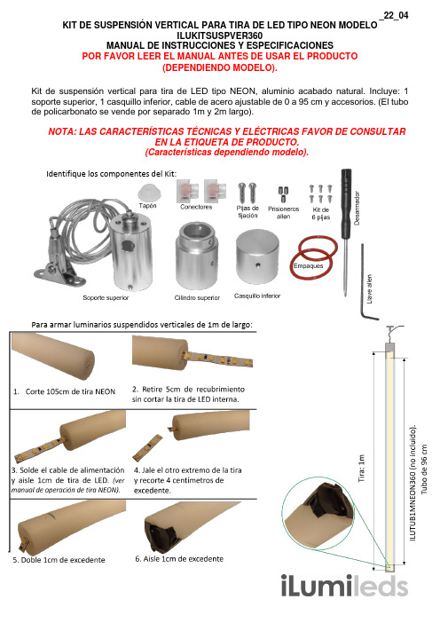
_22_04 KIT DE SUSPENSIÓN VERTICAL PARA TIRA DE LED TIPO NEON MODELOILUKITSUSPVER360MANUAL DE INSTRUCCIONES Y ESPECIFICACIONESPOR FAVOR LEER EL MANUAL ANTES DE USAR EL PRODUCTO(DEPENDIENDO MODELO).Kit de suspensión vertical para tira de LED tipo NEON, aluminio acabado natural. Incluye: 1 soporte superior, 1 casquillo inferior, cable de acero ajustable de 0 a 95 cm y accesorios. (El tubo de policarbonato se vende por separado 1m y 2m largo).NOTA: LAS CARACTERÍSTICAS TÉCNICAS Y ELÉCTRICAS FAVOR DE CONSULTAREN LA ETIQUETA DE PRODUCTO.(Características dependiendo modelo).Identifique los componentes del Kit:Para armar luminarios suspendidos verticales de 1m de largo:Para armar luminarios suspendidos verticales de 2m de largo:Notas:-Antes de fijar la tira de LEDs, se debe limpiar perfectamente la superficie donde instalará, asegurandose que quede libre de polvo, grasa y suciedad.-No use thiner o sustancias que puedan dañar la cubierta de la tira de LEDs.-Este producto debe ser instalado por personal calificado.-No haga dobleces pronunciados ni pise la tira de LEDs.-Consulte el manual de la fuente de poder a utilizar.-En caso de requerir alargar el cable de alimentación de la tira use cable del calibre adecuado dependiendo del consumo total de la tira y aisle correctamente usando cinta masilla y cinta vulcanizada para evitar filtraciones de humedad a través de los empalmes.-Evite perforar o dañar la cubierta de la tira de LEDs.-No conecte más de 5 m continuos. Al conectar un tramo de 5m se recomienta alimentar por ambos extremos para asegurar un brillo uniforme.-El uso de esta tira de LEDs en circuitos con ruido eléctrico generado por aparatos como motores, elevadores o generadores de electricidad entre otros puede disminuir su vida útil. El sello incorrecto en las uniones, cableado o terminaciones de tramos de tira puede provocar filtraciones de humedad y daño prematuro.-No utilice objetos diferentes a las grapas de fijación para instalar la tira.-No doble la tira en ángulos rectos ya que puede dañarse.No observar y cumplir las recomendaciones descritas en este manual puede ocasionar pérdida de garantíaPara calcular la fuente de poder adecuada, considere el que el voltaje de alimentación de la tira debe ser igual al voltaje de salida de la fuente. Para calcular la potencia de la fuente multiplique el consumo por metro por la cantidad de metros a utilizar. Siempre use las fuentes de poder a máximo el 80% de su potencia máxima (vea el manual de operación de la fuente a utilizar).PÓLIZA DE GARANTÍAMarca:Modelo:Importador: Ilumileds S.A. de C.V. Calz. San Isidro No. 97 Int. 2-2, Col. San Francisco Tetecala, Azcapotzalco, Ciudad de México, México, C.P. 02730. Tel.: (55)52072553Ilumileds S.A. de C.V. garantiza este producto por 1 año a partir de la fecha de compra en todas y cada una de sus partes y componentes contra cualquier defecto de los materiales y/o mano de obra empleados en su fabricación, sin costo para el consumidor.Ilumileds, S.A. de C.V. cubrirá los gastos de transportación del producto para lograr el cumplimiento de la garantía dentro de su red de servicio. Para hacer efectiva la garantía presente el producto acompañado de la póliza de garantía correspondiente debidamente sellada por el establecimiento que lo vendió, o la factura, o recibo o comprobante, en el que consten los datos específicos del producto objeto de la compraventa. El establecimiento en donde el consumidor puede hacer efectiva la garantía, así como adquirir las partes, componentes, consumibles y accesorios: es con el distribuidor autorizado donde el producto fue adquirido o directamente en nuestro centro de servicio ILUMILEDS ubicado en Callejón de Atenco No. 5, Col. San Martín Xochinahuac, Azcapotzalco, Ciudad de México, México, C.P. 02120.Tel. (55)26264751El tiempo de reparación de producto no será mayor a 30 días en ningún caso.Excepciones:La presente garantía no será válida en los siguientes casos:a) Cuando el producto hubiese sido utilizado en condiciones distintas a las normales.b) Cuando el producto no hubiese sido operado de acuerdo con el instructivo de uso que se le acompaña.c) Cuando el producto hubiese sido alterado o reparado por personas no autorizadas por el importador Ilumileds, S.A. de C.V.Fecha de compra:___________________________________________。
3X360R, 3X360GThree Plane LasersUsers Manual09/2020© 2020 Fluke Corporation. All rights reserved. Specifications are subject to change without notice.LIMITED WARRANTY AND LIMITATION OF LIABILITYThis Fluke product will be free from defects in material and workmanship for three years from the date of purchase. This warranty does not cover fuses, disposable batteries, or damage from accident, neglect, misuse, alteration, contamination, or abnormal conditions of operation or handling. Resellers are not authorized to extend any other warranty on Fluke’s behalf. To obtain service during the warranty period, contact your nearest Fluke authorized service center to obtain return authorization information, then send the product to that Service Center with a description of the problem.THIS WARRANTY IS YOUR ONLY REMEDY. NO OTHER WARRANTIES, SUCH AS FITNESS FOR A PARTICULAR PURPOSE, ARE EXPRESSED OR IMPLIED. FLUKE IS NOT LIABLE FOR ANY SPECIAL, INDIRECT, INCIDENTAL OR CONSEQUENTIAL DAMAGES OR LOSSES, ARISING FROM ANY CAUSE OR THEORY. Since some states or countries do not allow the exclusion or limitation of an implied warranty or of incidental or consequential damages, this limitation of liability may not apply to you.Fluke Corporation Fluke Europe B.V. ООО «Флюк СИАЙЭС»P.O. Box 9090 P.O. Box 1186 125167, г. Москва,Everett, WA 98206 5602 BD Eindhoven Ленинградский проспект дом 37,U.S.A. The Netherlands корпус 9, подъезд 4, 1 этаж11/99Table of ContentsTitle Page Introduction (1)How to Contact Fluke (1)Safety Information (1)Product Familiarization (3)Features (3)Lasers and Optical Glass (4)Controls (5)Check Product Accuracy (6)Cone Accuracy (6)Horizontal Leveling Accuracy (8)Vertical Accuracy (10)90 Degree Accuracy (12)Accessories (14)3X360 Magnetic L-bracket (14)Maintenance (15)Clean the Product (15)Replacing Battery (15)RBP5 Rechargeable Battery (16)Housing Glass Insert (16)Specifications (17)3X360R, 3X360G Users Manual3X360R, 3X360GIntroduction IntroductionThe 3X360R, 3X360G Three Plane Lasers (the Product) are battery powered, self-leveling, professional grade instruments. The 3X360R emit solid red line lasers. The 3X360G emit solid green line lasers. The 3X360R and 3X360G also emit vertical and horizontal point lasers 90 degrees from the Product. Use the Product to lay out reference points to align targets horizontally, vertically, or diagonally.NoteIf the laser beam is difficult to see, use either the XLD+ or SLDR or SLDG Laser Detector to accurately determine the location of the laser. See the XLD+ or SLDR or SLDG Users Manual.How to Contact FlukeTo contact Fluke, call one of the following telephone numbers:• Technical Support USA: 1-800-44-FLUKE (1-800-443-5853)• Calibration/Repair USA: 1-888-99-FLUKE (1-888-993-5853)• Canada: 1-800-36-FLUKE (1-800-363-5853)• Europe: +31 402-675-200• Japan: +81-3-6714-3114• Singapore: +65-6799-5566• China: +86-400-921-0835• Brazil: +55-11-3530-8901• Anywhere in the world: +1-425-446-5500Or, visit the PLS website at .To view, print, or download the latest manual supplement, visit .Safety InformationA Warning identifies conditions and procedures that are dangerous to the user. A Caution identifies conditions and procedures that can cause damage to the Product or the equipment under test.To prevent eye damage and personal injury:• Read all safety information before you use the Product.• Carefully read all instructions.• Do not alter the Product and use only as specified, or the protection supplied by the Product can be compromised.• Do not use the Product if it operates incorrectly.• Do not use the Product if it is altered or damaged.• Use the Product only as specified or hazardous laser radiation exposure can occur.• Do not look into the laser. Do not point laser directly at persons or animals or indirectly off reflective surfaces.• Do not look directly into the laser with optical tools (for example, binoculars, telescopes, microscopes). Optical tools can focus the laser and be dangerous to the eye.• Do not open the Product. The laser beam is dangerous to eyes.• Battery contains hazardous chemicals that can cause burns or explode. If exposure to chemicals occurs, clean with water and get medical aid.• Do not disassemble the battery.• Repair the Product before use if the battery leaks.• The battery door must be closed and locked before you operate the Product.• Remove the battery if the Product is not used for an extended period of time, or if stored in temperatures above 50 °C.If the battery is not removed, battery leakage can damage the Product.• Replace the battery when the low battery indicator shows to prevent incorrect measurements.• Use only Fluke approved power adapters to charge the battery. Refer to RBP5 manual for additional safety information and instructions.• Do not short the battery terminals together.• Do not disassemble or crush battery cells and battery packs.• Do not keep cells or battery in a container where the terminals can be shorted.3X360R, 3X360GUsers ManualTable 1 is a list of the symbols that can be used on the Product or in this manual.Table 1. SymbolsNoteIn colder climates, the Product needs sufficient time to warm up to achieve the stated accuracy measurements. Turn on both the horizontal and vertical lasers and wait 3 minutes before you take a measurement. When you move the Product between environments with large differences in ambient temperature, allow for an additional adjustment time.3X360R, 3X360GProduct Familiarization Product FamiliarizationThe manual explains features for multiple models. Because models have different features and accessories, not all of the information in the manual may apply to your Product.FeaturesUse Table 2 to identify the features and standard accessories of your Product.Table 2. FeaturesIn3X360R, 3X360GControls ControlsTable 4 lists the Controls of the Product.3X360R, 3X360GUsers ManualCheck Product AccuracyCone Accuracy1. Place the laser on a flat surface going in one direction.2. Turn on the horizontal beam and project on the parallel wall. You will need to have a set distance between (a,b)which will be referred to as "D" with the horizontal beam.illustration 1illustration 23. Rotate the laser 180 degrees horizontally and place at point b, as seen above .4. Turn on the horizontal beam and adjust the laser height so the center of the beam is aligned with mark b.3X360R, 3X360GCone Accuracyillustration 35. Mark c directly above or below a.6. Measure the distance between these two marks (a,c). If the measurement value is greater then the corresponding E value, take to your service provider.73X360R, 3X360GUsers ManualHorizontal Leveling AccuracyIt is important to conduct an accuracy check at the expected working distance for the specific use case and is illustrated in Table 6.1. Place the laser on a flat surface going in one direction. You will need to have a set distance between (a,b) which will bereferred to as "D".2. Turn on the horizontal beam and mark (a,b)a is 3.2ft (1m) away from laserillustration 13. Once “D” is identified based on illustration 1, rotate the laser 90 degrees horizontally as seen below.4. Mark c and calculate the distance between c,b and this is F.illustration 2893X360R, 3X360GHorizontal Leveling Accuracy5. Rotate the laser 180 degrees horizontally as seen below.6. Mark d and calculate the distance between d,b and this is E.illustration 37. Rotate the laser 270 degrees horizontally as seen below.8. Mark e and calculate the distance between e,b and this is G.9. If any of the values are greater than the respective E,F,G column values, take to your service provider.illustration 4103X360R, 3X360G Users ManualVertical AccuracyIt is important to conduct an accuracy check at the expected working distance for the specific use case and is illustrated in Table 7.1. Place the laser on a flat surface that is even in both directions across.a.The height of the room used should reflect with the corresponding values under column "J"illustration 13X360R, 3X360GVertical Accuracy2. Turn on both vertical beams +a. Mark two short lines where both vertical beams intersect on points (a,b) and (c,d).illustration 23. Pick up and rotate the laser 180 degrees then position the vertical beams with existing (a,b) marks. These marks on the ground become (e,f).4. On the ceiling, mark two short lines (g,h)illustration 35. Measure the distance between (h,d) and this value is K.6. Measure the distance between (c,g) and this value is L7. Review your applicable row for vertical distance is less than or equal to K & L. If greater than the values, take to your service provider.1190 Degree AccuracyChecking 90 degree accuracy requires a large open floor space. Distances A,B,C can be chosen based on your application and distance to use.1. Place the laser on a smooth, flat and stable surface that is level in both directions.2. Turn on the side vertical beam.3. Mark the center of the beam at three locations on the ground, as seen below at (a,b,c) and (b) should be the midpointof the entire line length.illustration 14. Move the laser to mark b and turn on both vertical beams +5. Position the beam crossing precisely at mark b.6. Mark location d along the front vertical beam at set distance C.illustration 2127. Rotate the laser 90 degrees horizontally8. Position the front and side vertical beams with (b).9. Mark e and measure the distance (D) beweetn (c,e).10. If the value is greater than D values, take to your service provider.illustration 3133X360R, 3X360GUsers ManualAccessoriesTable 9 is a list of the accessories available for the Product.Table 9. AccessoriesModel Description PN PLS HGI3X360R PLS Housing glass insert for PLS 3x360R5204916 PLS HGI3X360G PLS Housing glass insert for PLS 3x360G5214800 PLS 3X360 MLB Magnetic L-bracket w/ micro and elevation adj5214817 PLS 3X360 CB Ceiling bracket used w/ PLS 3X360 MLB5214821 PLS XLD+PLS Universal rotary/line laser detector w/ clamp5221059 PLS 3X360 HC PLS 3X360 blow mold hard case5221067 PLS RBP5Li-ion battery for handheld lasers w/ charging cord5023322 PLS RRT4Red magnetic reflective target5022629 PLS GRT4Green magnetic reflective target5022634 Note: PLS 3X360 is not compatible with PLS BP5 alkaline battery pack (PN 5031952)3X360 Magnetic L-bracket and Ceiling BracketPLS 3X360 CBFigure 13X360 MLB Magnetic L-bracketHorizontal rotation360◦Horizontal rotation precision adjustment YesElevation adjustment Max. 2.79 in (71 mm)Elevation adjustment lock*YesLaser level mounting screw1/4-20 UNC male threadedTripod mounting hole1/4-20 UNC female threaded, 5/8-11 UNC female threaded Wall hanging hole Max. 0.53 in (13.5 mm)Dimensions (H x W x D)Approx. 5.9 x 3.3 x 5.4 in (150 x 87.3 x 137 mm) Weight Approx. 0.86 lb (0.39 kg)Note: * the elevation adjustment lock provides 2X friction.143X360R, 3X360GMaintenance 3X360 CB Ceiling BracketCompatibility3X360 MLBClamp opening Max. 0.118 in (3 mm)Dimensions (H x W x D)Approx. 9.84 x 2.52 x 2.4 in (250 x 64 x 61 mm)Weight Approx. 0.84 lb(0.38 kg)MaintenanceTo maintain the Product, clean the case and optical glass and replace the batteries.The laser beam is dangerous to the eyes.Clean the ProductClean the case with a damp cloth and a weak soap solution.To clean the optical glass, use a pressurized can of air or a dry nitrogen-ion gun, if available, to blow off particulates from the optical surfaces.Replacing BatteryReplace the battery when the battery indicator LED is red.To install or replace RBP5 (Li-ion) using AA battery tray is not commended due to extremely short battery life (see Figure 2):1. Press down on the latch 1.2. While pressing down, pull back on battery pack and remove.3. Reinstall recharged battery pack.153X360R, 3X360GUsers ManualRBP5 Rechargeable BatteryFigure 3Housing Glass InsertIf the optical glass is damaged, replace the housing glass insert. See Table 6 for the part number to order for your Product. To replace the housing glass insert (see Figure 4):1. Remove the four housing glass insert screws2. Pull out the the tower insert and glass insert.3. Replace the insert and re-fasten screws.123Figure 4. Housing Glass Insert Replacement163X360R, 3X360GSpecifications SpecificationsSpecifications PLS 3X360R PLS 3X360GBattery (RBP5)Lithium-ion, 3.6 V, 5200 mAhBattery Life, Continuous Use (typical)3 beams: ≥ 9 hours1 beam: ≤ 30 hours3 beams: ≥ 5 hours1 beam: ≤ 17 hoursLine Fan AngleHorizontal360°Front Vertical360°Side Vertical360°Working RangeWithout line detector65 ft (20 m)115 ft (35 m) With line detector165 ft (50 m)210 ft (65 m) Accuracy± 5/64 in @ 33 ft (± 2 mm @ 10 m) Laser LevelingSystem Automatic PendulumRangeSelf-leveling: ≤ 4°Out of self-levelling: > 6°Leveling time≤ 3 sec TemperatureOperating14 °F to 122 °F (-10 °C to 50 °C)StorageWith Battery: -4 °F to 122 °F (-20 °C to 50 °C) Without Battery: -13 °F to 158 °F (-25 °C to 70 °C)Relative Humidity 0 % RH to 90 % RH (0 °C to 35 °C) 0 % RH to 75 % RH (35 °C to 40 °C) 0 % RH to 45 % RH (40 °C to 50 °C)IP rating IP 54Drop test 3.28 ft (1 m)Battery status indication 100%, 75%, 50%, 25% and low batterySize (H x W x L) w/ RBP5 5.12 in x 3.58 in x 5.25 in (13 cm x 9.09 cm x 13.33 cm) Weight (with battery) 1.76 lbs (0.8 kg)Li-ion battery safety IEC 62133Laser Safety Class 2 (IEC 60825-1) Light Source Semiconduction laser diodeMax Output Power< 1 mWWavelengthRed635 nm ± 10 nmGreen520 nm ± 10 nm Electromagnetic Compatibility (EMC)International IEC 61326-1Korea (KCC) Class A Equipment (Industrial Broadcasting & Communication Equipment) [1][1] This product meets requirements for industrial (Class A) electromagnetic wave equipment and the seller or user should take notice of it. This equipment is intended for use in business environments and is not to be used in homes.USA (FCC) 47 47 CFR 15 subpart B. This product is considered an exempt device per clause 15.103.17。
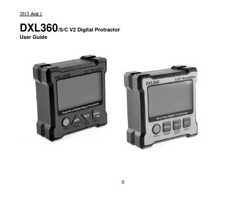
DXL360/S/C V2 Digital Protractor User GuideFeatures:1) DXL360S/C: High accuracy ±0.05°, high resolution 0.01°DXL360: ±0.1°, resolution 0.02°, detail check specification2) Dual and Single axis with user friendly LCD display angle3) Rechargeable4) V Shape metal case for easy to fit at the corner or pipe.5) 5 Side Magnetic base6) Audible alarming at settable angle range7) Any angle measurement *DXL360s/c only8) USB / Bluetooth to pc connection need adapter for DXL360 and DXL360s/c. SpecificationsAccuracy:DXL360S/C:0 to 20°: ± (0.05°)20 to 70°: ± (0.1°)70 to 90°: ± (0.05°)DXL360:0 to 20°: ± (0.1°)20 to 70°: ± (0.2°)70 to 90°: ± (0.1°)*After CalibratedMeasuring range:Single axis: 360°, Dual axis: ±40°Resolution:DXL360S/C: 0.01°DXL360: 0.02°Any Angle Measurement 0.5°Accuracy *DXL360s/c:Gyro Rotation Speed *DXL360s/c: <50°/sResponse time: <0.4 secondAudio sound:60dB @ 30cmZero offset drift angle per °C: 0.0058° (typical)Operating temperature: 0 to 50°CStorage temperature: -10 to 60°CUser Interface: Mono-color LCD with backlight Supply Power: Rechargeable Li-Polymer 3.7V Charger port:5V 500mA Mini type-B USB port Power Consumption: Standby: 10uA, Operation: 20mA. Standby Battery Life:4000 hoursOperating Battery Life: 40 hoursDimensions(in mm):70(L) x 70(W) x 23(H)Magnetic Base: affix at 4 cornerMagnetic Force: N48Weight: 120gramButton FunctionsButtonFunction DescriptionsNormal Mode MENU ModePOWER In normal operation, this button turns the deviceON/OFF.Serves as theescape key atmenu modeZERO When pressed, the current reading is set tozero; subsequent measurements are relative tothis reading. The LCD will show the icon toindicate the device is in zero mode.Press and hold for 3 seconds to enable ordisable sound. The icon on LCD will bedisplaced accordingly. The buzzer alarmingcould be set at different accuracy level. Refer tosection “Angle Alarming”.Serves as theupward key foroption selection.HOLD When pressed, the current value will freeze; theunit icon flashes to indicate the readingis on hold.Serves as thedownward key atmenu modeSET Press and hold for 3 seconds to enter MENUmode, for set mode options.Serves as the Setkey.ANGLE *DXL360S/Conly Any angle measurement start button. Refer tosection “Any Angle”Press and hold for 3 seconds to enter MENUmode, for set mode options.Serves as the Setkey.LCD Icons RepresentationsBattery status indication iconsThese icons indicate the battery level. There are 3 levelsrepresenting empty, half and full.In dual-axis mode, the LCD displays the direction of tiltgraphically. It will show as E bubble to display the direction of tiltDegree mode. Flash when unit is in HOLD modemm/M, the height of one end for 1m long plate.Gradient % mode. Flash when unit is in HOLD mode*DXL360S/C OnlySound notification on.Blank as offShow this logo as relative value is showing. When the Zerobutton is pressed, the unit reset current angle to zero.Direction of tilt icons, show the tilt angle directionDual-Axis Mode. Both the X and Y axis angle will be showed.Dual axis mode measures inclination up to +-40 degree for eachaxis before it automatically switch to single axis mode.Single Axis Mode. Measure slope up to +-90 degree.The triangle icon indicates the direction of tilt with respect to thebottom right corner of the unit.Battery ChargingIt has a built in Lithium Ion rechargeable battery. A standard charger is supplied that the input voltage is 110V to 240V AC, 50/60Hz, and the output is 5V DC, 500mA. The charger operating procedure is list below:1) Plug the Charger into AC socket, the RED indicator on the charger should turnedON,2) Plug the USB charging cable to the Charger,3) Insert the other end of the USB cable to the unit,4) The battery icon on the LCD blinks to indicate charging in process. Upon chargingcomplete, the icon stops blinking.5) The charging time is approx. 3 hours.The unit could also be charged by connecting the USB cable to the unit and a computer’s USB port. This has the same effect when charging the unit with the provided adaptor. Note: When the unit is turned OFF, and plug in the USB charge cable, the LCD will no show anything, it is NORMAL. Once the unit is turned ON, the battery icon should flash indicating the unit is in charging mode.Relative/ Absolute MeasurementRelative MeasurementLCD Icon:Absolute MeasurementLCD Icon: BlankRelative and Absolute Mode Switching:1 Pre ss and release the “ZERO” key to set the relative measurement zeropoint2 Press and release the “ZERO” key to cancel the relative zero point andback to absolute measurement mode.Hold FunctionHolding Mode:LCD Icon blinking:Holding function:1. Press and release the “HOLD” key to activate holding function, digit willfreeze.2. Press and release the “HOLD” key to cancel the holding function.Auto Power OffFor no movement in 30 minutes, the unit will power off.Or we can set to never sleep mode at below instruction.Power auto off setting:1. Press and hold “SET” / “ANGLE” key and enter MENU mode2. Select “POWER” by “ZERO” and “HOLD” key, press “SET” key to enter Powermode3. Scroll “NEVER” or “30MIN” by “ON/OFF” and “HOLD” key4. Press “SET” key to confi rm NEVER or 30MIN (30 minutes) sleepRestore Factory SettingWhen you find that the unit is abnormal, you can restore the unit to factory setting.All calibration setting will be restored to factory setting.*Not suggest restore to factory setting in normal status, for accuracy drift, please follow Calibration. After factory set, please redo calibration to ensure the accuracy. Restore to factory setting:1. Press and hold “SET ” / “ANGLE ” key and enter MENU mode2. Select “FACTORY SET” by “ZERO ” and “HOLD” key, press “SET ” key to enter FACTORY SET mode3. Scroll “YES” or “NO” by “ZERO ” and “HOLD” key4. Press “SET ” key to confirmAngle Alarming Alarming Mode: LCD Icon:Alarming Angle setting:1. Press and hold “SET ” / “ANGLE ” key and enter MENU mode2. Select “BUZZER” by “ZERO ” and “HOLD” key,press “SET ” or “ANGLE ” key to enter BUZZER settingPress and hold “ZERO ” and “HOLD” key for fast scrolling the digit. 3. Press “SET ” or “ANGLE ” to enter setting valueBUZZER>SINGLE : 0 0 . 0 0 DUAL. X: 0 0 . 0 0 DUAL. Y: 0 0 . 0 0 RANGE : 0 0 . 5 0 ACTIVE : IN OUTSINGLE Vertical / Single axis mode alarming angle (Degree)DUAL.X Horizontal/ Dual axis mode X axis alarming angle (Degree)DUAL.Y Horizontal/ Dual axis mode Y axis alarming angle (Degree)RANGE The range (Degree)that will trigger the audible alarmingFor example: SINGLE. set to 20.00RANGE set to 01.00While the unit is in +19° to +21°or -19° to -21°, the unit will alarm ACTIVE IN or OUT to set the alarm will alarm in of range or out of rangeCalibrationCalibrate the unit, once you found that there is accuracy drift on the unit. You can verify the accuracy at below step:At Step1, you measured X and Y value, X1 and Y1At Step2, you measured X2 and Y2, in theory X1=-X2, Y1=-Y2.If the error is too large, you can enter calibration mode to eliminate the errorAccuracy drift is causing by large ambient temperature change (5 to 10 Degree Celsius)or the unit has been dropped.Calibration Procedure:Step 1: Press and hold the “SET” or “ANGLE” key enter Menu mode. Select “Calibration” mode, press “SET”. Place the unit on a flat table (no need perfect level table) LCD display “CALIBRATE DUAL AXIS PRESS SET”, press “SET” and buzzer will beep; wait until the beep sound stop. While the buzzer is beeping keep the unit stable.Step 2: Then rotate the unit 180 degree with the other side against the same place.Press the Set button again, and wait for the beep finished.Step 3:LCD display “CALIBRATE HORIZONTAL PRESS SET”. Place the unit horizontal like the picture “STEP 3” and then press “SET”, wait until the beep sound stop.Step 4: Then rotat e the unit 180 degree at the same place. Press the “ZERO” button again, and wait for the beep finished.Step 5:LCD display “CALIBRATE VERTICAL PRESS SET”, mention that the ON/OFF Key at upper side, hold on a flat wall. And then press “SET” Key. Wait for the “Beep” sound stop.Step 6: Then rotate the unit 180 degree with the other side against the same place of wall (ON/OFF Key at upper side). Press the Set button again, and wait for the beep finished. Now, the LCD should go back to the selection menu. The calibration is done, by selecting “Back” to go back for normal operationANY ANGLE measurement: *DXL360S/C onlyAny angle measurement is using gyro technique.You can measure the angle between two faces, not only in earth gravity direction.1) Press Angle key at the first face, and then rotate slowly and must keep the rotationaxis to another testing face2) It will then show the angle once you not move the unit.The rotation axis:Any Angle Measurement Method:Example: Measure angle between two wooden walls is 88.9°Calibrate Gyro *DXL360S1) Place Unit At Flat Table And then Press Set2) Flip 360 degree in clockwise and then press setPlease rotate slowly to increase the accuracy3) Place unit at flat table and then press set4) Flip 360 degree counter clockwise and then press setPlease rotate slowly to increase the accuracyPC CommunicationIt has a PC data logging function.For DXL360SC you can directly plug the USB cable between PC and protractor by miniUSB cableFor DXL360/S You can not directly plug the USB cable between PC to protractor by a general USB cable.You need to optional purchase the PC adapter SVRS232You can continue to data logging X and Y inclination data to PC.Sampling time is around 2 Hz.Specification:1) RS232 Com Port 9600 baud rate2) USB connection ( include a RS232 to USB adapter)3) Format will output ASCII: example for x is 0, Y is -88.88 X+0000Y-8888 Detail can visit our website or contact our sales person.DXL360/S/C V2 数字角度尺使用说明书产品特点:1) DXL360S/C: 高精度±0.05°, 高分辨率0.01°DXL360: 精度±0.1°, 分辨率0.02°, 详情参阅说明书。
GARANTÍA LIMITADAAL USAR SU XBOX 360 S O ACCESORIO USTED ESTÁ ACEPTANDO ESTA GARANTÍA.ANTES DE INSTALARLO, LEA CUIDADOSAMENTE ESTA GARANTÍA.SI NO ACEPTA ESTA GARANTÍA, NO USE SU XBOX 360 S O ACCESORIO. DEVUÉLVALO SIN USAR A SU DISTRIBUIDOR O A MICROSOFT PARA UN REEMBOLSO. Comuníquese a Microsoft en, / al (800) 4MY‐XBOX o al (800) 469‐9269. Esta garantía le otorga derechos legales específicos. Es posible que usted tenga otros derechos dependiendo del Estado o la Provincia donde reside.1. Definiciones(a) “Xbox 360 S” significa una consola Xbox 360 S nueva adquirida con undistribuidor autorizado.(b) “Accesorio” significa equipo físico (hardware) nuevo para Xbox 360 o Xbox 360S de marca Microsoft adquirido con un distribuidor autorizado. Una unidad dedisco duro (HDD) es un accesorio si preinstalado o adquirir por separado.(c) "Periodo de Garantía" para Xbox 360 S, significa 1 año a partir de la fecha decompra del artículo; y para los Accesorios, significa 90 días a partir de la fechade compra.(d) “Usted” significa el usuario original final.(e) “Condiciones de Uso Normal” significa el uso normal por el consumidor bajocondiciones caseras normales de acuerdo al manual de instrucciones para elXbox 360 S o el Accesorio.(f) “Estado” significa un Estado, el Distrito de Columbia, y cualquier otro territorioo posesión de los Estados Unidos. “Los Estados Unidos de América” incluyetodos los anteriores.2. Garantía(a) Durante el Periodo de Garantía Microsoft le garantiza que el Xbox 360 S o elAccesorio no fallarán bajo Condiciones de Uso Normal.(b) Esta es la única garantía que le da Microsoft para su Xbox 360 S o el Accesorioy Microsoft no otorga ninguna otra promesa, garantía o condición. Nadie máspuede otorgar ninguna promesa, garantía o condición en nombre deMicrosoft.(c) EN CASO DE QUE LA LEY DEL ESTADO O LA PROVINCIA DONDE VIVE OTORGUEUNA GARANTÍA IMPLÍCITA, INCLUYENDO UNA GARANTÍA IMPLÍCITA DE COMERCIABILIDAD O IDONEIDAD PARA UN FIN PARTICULAR, SU DURACIÓN SELIMITARÁ AL PERIODO DE GARANTÍA. Algunos estados o provincias noconceden limitaciones en la duración de una garantía implícita, por lo que esposible que esta limitación no aplique en su caso.3. Para obtener el Servicio de Garantía(a) Antes de iniciar el proceso de garantía consulte los consejos en la secciónsolución de problemas en /en‐US (en Estados Unidos) o/en‐CA (en Canadá).(b) Si los consejos de la sección solución de problemas no resuelven su problema,siga el proceso en línea en /en‐US (en Estados Unidos) o/en‐CA (en Canadá). Si no tiene acceso a Internet, llameal (800) 4MY‐XBOX o (800) 469‐9269.(c) Antes de enviar su Xbox 360 S o el Accesorio para servicio a Microsoft,asegúrese de sacar una copia de cualquier dato que quiera conservar y eliminecualquier elemento que considere confidencial. Microsoft no se haceresponsable de su información y puede borrarla.4. Responsabilidad de Microsoft(a) Después de que devuelve su Xbox 360 S o Accesorio, Microsoft loinspeccionará(b) Si Microsoft determina que el Xbox 360 S o Accesorio se averiaron durante elPeriodo de Garantía bajo condiciones de uso normal, Microsoft (a sudiscreción) los reparará o sustituirá, o le reembolsará el precio de compra. Lareparación puede requerir partes nuevas o reconstruidas. La reposición podráhacerse con una unidad nueva o reconstruida.(c) Después de la reparación o reposición su Xbox 360 S o el Accesorio estaránbajo la protección de esta garantía por el resto de su Periodo de Garantíaoriginal o durante 95 días después de que Microsoft se lo haya enviado.(d) LA RESPONSABILIDAD DE MICROSOFT DE REPARAR O REEMPLAZAR SU XBOX360 S O EL ACCESORIO, O DE REEMBOLSAR EL PRECIO DE COMPRA, ES SURECURSO EXCLUSIVO.(e) Si su Xbox 360 S o Accesorio fallan una vez que se termina el Periodo deGarantía, no habrá garantía de ninguna clase. Después del vencimiento delPeriodo de Garantía Microsoft le cobrará un cargo por sus esfuerzos endiagnosticar y proporcionar servicio a cualquier problema que tenga su Xbox360 S o Accesorio.5. Exclusiones de la GarantíaMicrosoft no se hace responsable y esta garantía no aplica si su Xbox 360 S o Accesorio:(a) se dañan al ser usados con productos no vendidos o que no tienen licencia deMicrosoft (incluyendo, por ejemplo, juegos y accesorios no fabricados o sinlicencia de Microsoft y juegos “pirata”, etc.);(b) se usan con fines comerciales (incluyendo, por ejemplo, renta, pago por juego,etc.);(c) se abren, modifican o son indebidamente manipulados (incluyendo porejemplo, cualquier intento de vencer cualquier limitación técnica, protección omecanismo contra piratería del Xbox 360 S o Accesorio, etc.), o se altera oremueve su número de serie;(d) se dañan por cualquier causa externa (incluyendo, por ejemplo, si se dejancaer, se usan con ventilación inadecuada, etc., o no se siguen las instruccionesdel manual de instrucciones del Xbox 360 S o el Accesorio); o(e) son reparados por cualquier servicio que no sea Microsoft.6. EXCLUSIÓN DE CIERTOS DAÑOSMICROSOFT NO SE HACE RESPONSABLE POR NINGÚN DAÑO INDIRECTO, INCIDENTAL, ESPECIAL O CONSECUENCIAL; CUALQUIER PÉRDIDA DE DATOS, PRIVACIDAD, CONFIDENCIALIDAD O GANANCIAS; O CUALQUIER INCAPACIDAD DE USAR SU XBOX 360 S O ACCESORIO. ESTAS EXCLUSIONES APLICAN INCLUSO, SI SE INFORMÓ A MICROSOFT SOBRE LA POSIBILIDAD DE ESTOS DAÑOS E INCLUSO SI ALGÚN RECURSO NO LOGRA SU OBJETIVO ESENCIAL. Algunos estados o provincias no conceden la exclusión o limitación de daños incidentales o consecuenciales, por lo que es posible que esta limitación o exclusión no aplique en su caso.7. Términos adicionalesSi intenta vencer o evadir alguna limitación técnica, protección o sistema contra piratería en su Xbox 360 S o Accesorio, pudiera ocasionar que dejen de funcionar de manera permanente. También anulará su garantía y su Xbox 360 S o Accesorio no podrán recibir reparación autorizada, ni siquiera mediante pago.8. Elección de ley(a) Si adquirió su Xbox 360 S o Accesorio en los Estados Unidos, la ley del Estadode Washington regula la interpretación de esta garantía y cualquierreclamación de que Microsoft dejó de cumplir con ella, independientementede los principios para conflictos de leyes.(b) Si adquirió su Xbox 360 S o Accesorio en Canadá, la ley de la Provincia deOntario regula la interpretación de esta garantía y cualquier reclamación deque Microsoft dejó de cumplir con ella, independientemente de los principiospara conflictos de leyes.(c) Las leyes del Estado o Provincia donde usted vive regularán todas las otrasreclamaciones (incluyendo las demandas para protección de consumidores,competencia desleal, garantía implícita y por actos ilícitos).Todas las partes de esta Garantía Limitada aplican en la máxima medida permitida por la ley o salvo que lo prohíba la ley.9. Esta garantía es válida solamente en los Estados Unidos de América y en Canadá.Domicilio de Microsoft en los Estados Unidos: Microsoft Corporation, One Microsoft Way, Redmond, WA 98052Domicilio de Microsoft en Canadá: Microsoft Canada Inc., 1950 Meadowvale Blvd., Mississauga, Ontario, L5N 8L9_____________________________________________________________________________LICENCIA DE SOFTWAREAL USAR SU XBOX 360 S O EL ACCESORIO AUTORIZADO USTED ESTÁ ACEPTANDO ESTA LICENCIA DE SOFTWARE. ANTES DE INSTALARLO LEA CUIDADOSAMENTE ESTA LICENCIA DE SOFTWARE. SI NO ACEPTA ESTA LICENCIA DE SOFTWARE, NO USE SU XBOX 360 S O ACCESORIO AUTORIZADO. DEVUÉLVALO SIN USAR A SU DISTRIBUIDOR O A MICROSOFT PARA UN REEMBOLSO. Comuníquese a Microsoft, en / al (800) 4MY‐XBOX o al (800) 469‐9269.1. Definiciones(a) “Xbox 360 S” significa una consola Xbox 360 S.(b) “Accesorio Autorizado” significa un accesorio del equipo físico (hardware)nuevo para Xbox 360 o Xbox 360 S de marca Microsoft y un accesorio deequipo físico (hardware) para Xbox 360 o Xbox 360 S con marca de terceraparte y que tiene licencia de Microsoft, cuyo empaque porta el logotipo oficial“Con licencia para Xbox”.Una unidad de disco duro (HDD) es un accesorio sipreinstalado o adquirir por separado.(c) “Juegos Autorizados” significa los juegos del Xbox 360 o el Xbox 360 S endiscos de juegos publicados por o con licencia de Microsoft y el contenido delos juegos descargado desde el servicio Xbox LIVE de Microsoft o la páginaWeb (por ejemplo, avatares, juegos descargables, expansiones dejuegos, etc.).(d) “Software” significa el programa de cómputo preinstalado en el Xbox 360 S oAccesorio Autorizado, incluyendo cualquier actualización que Microsoftpudiera facilitar de cuando en cuando.(e) “Accesorios No Autorizados” significa todos los accesorios del equipo físico(hardware) diferentes al Accesorio Autorizado, con excepción de tarjetas dememoria USB, cámaras digitales utilizadas para sacar fotografías o películas yreproductores de música usados para reproducir música o reproducir películaso videos que no son Accesorios No Autorizados.Unidades de disco duro(HDDs) son accesorios si preinstalado o adquirir por separado.(f) “Juegos No Autorizados” significa todos los discos de juegos, descargas dejuegos y contenido de juego o medios diferentes a los Juegos Autorizados.(g) “Software No Autorizado” significa cualquier programa de cómputo nodistribuido por Microsoft a través de discos de juegos para Xbox 360 o Xbox360 S publicados por o con licencia de Microsoft, servicio Xbox LIVE deMicrosoft o la página Web .(h) “Usted” significa el usuario del Xbox 360 S o el Accesorio Autorizado.2. Licencia(a) Usted está recibiendo el Software bajo licencia, no en venta. Tiene licenciapara usar el Software únicamente como está preinstalado en su Xbox 360 S oAccesorio Autorizado, y con las actualizaciones periódicas de Microsoft. Nopuede copiar o rediseñar el Software.(b) Como condiciones para esta licencia de Software, usted acepta que:(i) Sólo usará Accesorios y Juegos Autorizados con su Xbox 360 S oAccesorio Autorizado. No usará Accesorios o Juegos No Autorizados.Es posible que no funcionen o dejen de funcionar de manerapermanente después de una actualización del Software.(ii) No usará ni instalará Software No Autorizado. Si lo utiliza es posibleque su Xbox 360 S o Accesorio Autorizado dejen de funcionar demanera permanente en ese momento o después de unaactualización posterior del Software.(iii) No intentará vencer o evadir cualquier limitación técnica, protección osistema contra piratería en el Xbox 360 S o Accesorio Autorizado. Si lointenta, es posible que su Xbox 360 S o Accesorio Autorizado dejen defuncionar de manera permanente en ese momento o después de unaactualización posterior del Software.(iv) Microsoft podrá adoptar medidas técnicas, incluyendo lasactualizaciones del Software, para evitar el uso de Accesorios y JuegosNo Autorizados, y para proteger las limitaciones técnicas, la seguridady el sistema contra piratería del Xbox 360 S o Accesorio Autorizado.(v) Microsoft podrá actualizar el Software de vez en cuando sin avisarlede antemano, por ejemplo, actualizar cualquier limitación técnica,protección o sistema contra piratería.3. Garantía.El Software está protegido por la Garantía Limitada que se otorga a su Xbox 360 S o Accesorio Autorizado y Microsoft no otorga ninguna otra garantía, promesa o condición en favor del Software. Nadie puede otorgar garantías o condiciones en nombre de Microsoft.4. EXCLUSION DE CIERTOS DAÑOSMICROSOFT NO SE HACE RESPONSABLE DE NINGÚN DAÑO INDIRECTO, INCIDENTAL, ESPECIAL O CONSECUENCIAL; CUALQUIER PÉRDIDA DE DATOS, PRIVACIDAD, CONFIDENCIALIDAD O GANANCIAS; O CUALQUIER INCAPACIDAD DE USAR EL SOFTWARE. ESTAS EXCLUSIONES APLICAN INCLUSO SI SE INFORMÓ A MICROSOFT SOBRE LA POSIBILIDAD DE ESTOS DAÑOS E INCLUSO SI ALGÚN RECURSO NO LOGRA SU OBJETIVO ESENCIAL. Algunos estados o provincias no conceden la exclusión o limitación de daños incidentales o consecuenciales, por lo que es posible que esta limitación o exclusión no aplique en su caso.5. Elección de Ley(a) Si adquirió su Xbox 360 S o Accesorio en los Estados Unidos, la ley del Estadode Washington regula la interpretación de esta garantía y cualquierreclamación de que Microsoft dejó de cumplir con ella, independientementede los principios para conflictos de leyes.(b) Si adquirió su Xbox 360 S o Accesorio en Canadá, la ley de la Provincia deOntario regula la interpretación de esta garantía y cualquier reclamación deque Microsoft dejó de cumplir con ella, independientemente de los principiospara conflictos de leyes.(c) Las leyes del Estado o Provincia donde usted vive regularán todas las otrasreclamaciones (incluyendo las demandas para protección de consumidores,competencia desleal, garantía implícita y por actos ilícitos).Este acuerdo no es aplicable en la máxima medida permitida en la ley y salvo que la ley lo prohíba. Este acuerdo no modifica sus derechos conforme a las leyes del estado o del país donde usted vive si las leyes del estado o el país donde vive no lo permiten.。
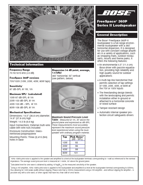
Maximum Sound Pressure Level Table : Measured at 1m, 30˚ above theground plane and expressed as dB-SPL.These measurements most accurately Technical InformationFrequency Range70 Hz to15kHz (±3 dB)Dispersion (-6 dB point, average,1-4 kHz)Engineers’ and Architects’SpecificationsThe loudspeaker shall be a ported loudspeaker system utilizing one 4.5"(11.4 cm) HVC environmental full-range driver mounted in the underside of the top of the loudspeaker enclo-sure. The driver shall have a ratedimpedance of 4Ω and shall be wired in parallel with a line voltage-matching (stepdown) transformer with taps at 10, 20, 40, or 80 watts.The loudspeaker shall have a single-port vented system, with a maximum acoustic output of 101 dB-SPL from 70 Hz to 15 kHz, with measurements referenced with full-bandwidth pink noise at 1 meter at the loudspeaker’s rated power.The input connection shall consist of wires with wire nuts on a cable at-tached to the base of the loudspeaker.The nominal dispersion of the loud-speaker shall be 360˚ horizontal and 50˚ vertical.The loudspeaker shall be theFreeSpace 360P Series II loudspeaker.Warranty InformationThe Bose FreeSpace 360P Series II loudspeaker is covered by a 5-year,transferable limited warranty.Loudspeaker ConfigurationSafety and Regulatory ComplianceThe FreeSpace ® 360P Series II loudspeaker is suitable for general purpose use. It complies with EMC Directive 89/336/EEC and Article 10(1) of the Directive in compliance with EN50081-1, EN50082-1, as signified by the CE mark.©2003 Bose Corporation, The Mountain,Framingham, MA 01701-9168PN263937 AM Rev.01 PC032065 JN31068Subject to change without notice.The FreeSpace ® 360P Series IIloudspeaker is designed for use in a distributed sound system when used with a constant voltage amplifier.The loudspeaker is packaged as one single unit per carton.For linear spacing (for bordering sidewalks, paths or walkways): Use the ratios shown above left, keeping the speaker at least 3 ft (1 m) from the listeners.Direct Field Coverage and Placement• To achieve ±1.5 dB, use 10 ft (3 m) spacing as X, center to center.• To achieve ±3.0 dB, use 20 ft (6 m) spacing as X, center to center.• To achieve ±6.0 dB, use 30 ft (9 m) spacing as X, center to center.To diagram your loudspeaker placement, as shown below, start in the upper left-hand corner and move down and to the right.The FreeSpace 360P-II loudspeakers are complete and ready for in-ground installation. Mounting each loud-speaker securely on a horizontal surface requires three #10 (M4)screws, which the installer must provide.Installation options include in-ground (with up to 40% of the enclosure buried in earth), or attached to a horizontal surface (a wooden deck or concrete patio, for example).Product color is green and blends with most surroundings. Painting is not recommended.It is recommended to use theFreeSpace 360P-II with a 2nd-order or higher high-pass filter at 70 Hz.Note: The FreeSpace 360P Series II loudspeaker is equipped with a protection circuit that reduces the low-frequency output when over-powered. In the event that the protec-tion circuit is activated, turn off the signal source for 30 seconds for full recovery.Installation。

Sx/Sb-Series 12” SystemsRigging ManualSx-SeriesThe Mb KitsElectro-Voice® manufactures three accessories to make the sus-pension of Sx/Sb-Series enclosures safe, easy and cost-effective: the Mb100 Eyebolt Attachment Kit, the Mb200 Installation Kit and the Mb300 Horizontal Array Kit. This instruction sheet gives a brief overview of how each of these suspension kits could be used so the correct kit can be selected. In addition, each of the suspension kits includes a separate instruction sheet with complete dimensions and full details for use.Suspending Sx/Sb-Series EnclosuresThe molded enclosures used in Sx/Sb-Series are lightweight and structurally sound. Each enclosure has four metric M8 x 1.25 metal inserts molded into the enclosure to aid in suspension and aiming. A single insert, correctly used, will safely suspend the weight of one enclosure with a safety factor in excess of 5 to 1. It will not support additional weight with a sufficient safety factor for overhead lifting. If multiple Sx/Sb-Series enclosures are suspended, Mb200 Installation Kits must be used to support and aim each enclosure.Mb100 Eyebolt Attachment KitThe Mb100 Eyebolt Attachment Kit is intended for very simple instal-lations only, to suspend an individual Sx/Sb-Series loudspeaker in a near-vertical orientation (see Figure 1). A second, redundant insert point is provided in the top of the enclosure so a supplementaryindependent means of suspension can be attached when regulations specify. The enclosure can be positioned to angle downward slightly through the use of the pull-up point at the back of the enclosure.Note that two top suspension cables should be used at all times to provide needed stability to the installation (see Figure 1).Do not suspend Sx/Sb-Series enclosures face down from the ceiling using the Mb100 Eyebolt Attachment Kit. The M8 eyebolts are not rated for lifting loads at 90°, and such a configuration makes stabilization of the enclosure difficult. Instead, use the Mb200 Installation Kit for this and most other situations (see the Mb200 Installation Kit section).Mb200 Installation KitThe Mb200 Installation Kit provides a cost-effective and safe means of attaching Sx/Sb-Series loudspeakers to walls or suspending them overhead (see Figure 2). The kit contains a large, reinforced-steel bracket with a selection of thru-holes which allow the bracket to be mounted to different surfaces in a range of orientations. This kit is rec-ommended for most installations, and is essential when arraying Sx/Sb-Series loudspeakers.The Mb200 U-bracket extends from top to bottom of the Sx/Sb-Se-ries loudspeaker and attaches at both ends. This securely “captures” the enclosure, allowing further loudspeaker systems to be added without increasing the stress on the first enclosure. It also allows the loudspeaker to be aimed in the desired direction and locked in place. For even greater flexibility, three-hole-pattern groups compatible with the OmniMount® 60.0 (originally Series 100)1 support system have also been incorporated into the Mb200 Installation Kit's U-bracket (see Figure 2B, reference A).Vertical arrays can be constructed by "daisy chaining" Mb200's to-gether (see Figure 3). To achieve a slight downward angle, attach an additional cable to the lower Mb200 and use this cable to pull up the array, securing the cable at the desired angle and position.No more than two enclosures should be suspended in a vertical array in this manner. If a taller array is required, you should provide a means of independent suspension for the remaining enclosures.Again, note the use of two top suspension cables (see Figure 3) which provide stability and should be used at all times.Horizontal ArrayNumber of Enclosuresin Array:Number of Kits Required Mb200Mb3002213324435546(Complete Circle)66Each Mb300 Horizontal Array Kit consists of two connector brackets (one top, one bottom) plus the hardware required to join these brack-ets to the U-brackets from two Mb200 Installation Kits. This combina-tion of one Mb300 Horizontal Array Kit plus two Mb200 Installation Kits forms a solid frame suitable for suspending two Sx/Sb-Series loudspeakers in a horizontal array (see Figure 4). Holes are provided in the Mb300 brackets for attaching cables for suspension.Two mounting angles, 50° and 60°, are possible using the Mb300 Horizontal Array Kit. Use of the 50° angle results in a tight array with speaker sides touching (see Figure 5); use of the wider orientation results in improved coverage for multiple loudspeakers and allows construction of a complete, 360° array (see Figure 6 for diagram of one half of a 360° array). A vertical array can also be constructed using the Mb300 Horizontal Array Kit, but relatively few aiming angles are available.1. OmniMount® is a registered trademark of OmniMount Systems, Inc.For more information, visit Mb300 Horizontal Array KitThe Mb300 Horizontal Array Kit must be used in conjunction with the Mb200 Installation Kit. Select the required number of kits from the chart below:Figure 1:Overhead Suspension Using the Mb100 Eyebolt Attachment Kit Figure 2a:Wall Mounting Using the Mb200 Installation KitFigure 2b:Vertical Overhead Suspension Using theMb200 Installation KitFigure 2c:Horizontal Overhead Suspension Using the Mb200 Installation KitFigure 3:Vertical Array Using the Mb200 Installation Kit12000 Portland Avenue South, Burnsville, MN 55337Phone: 952/884-4051, Fax: 952/884-0043Electro-Voice ®Figure 4a:Brackets from One Mb300 Horizontal Array Kit and TwoMb200 Installation Kits, Positioned for AssemblyFigure 4b:Assembled Horizontal Array Mounting Frame Consisting ofOne Mb300 Horizontal Array Kit and Two Mb200Installation KitsFigure 4c:Two Enclosure Horizontal Array Using the Mb300Horizontal Array Kit Figure 4d:Orientation for Full Circle (360°) Array Using the Mb300Horizontal Array Kit (Partial Array Shown)U.S.A. and Canada only. For customer orders, contact Customer Service at:800/392-3497 Fax: 800/955-6831Europe, Africa, and Middle East only. For customer orders, contact Customer Service at:+ 49 9421-706 0 Fax: + 49 9421-706 265Other Internatonal locations. For customer orders, Contact Customer Service at:+ 1 952 884-4051 Fax: + 1 952 887-9212。

目录简介 (1)1.1外观 (1)1.2开关机 (4)1.3快速测量 (5)1.4保存、删除和查看红外图像 (10)1.5红外热成像显示屏 (14)1.6控制键和扳机键 (15)1.7充电及导出图片 (15)1.7.1充电 (15)1.7.2导出图片 (16)操作和设置 (17)2.1主界面操作 (17)2.1.1快捷操作 (17)2.1.1.1快速切换色板 (17)2.1.1.2快速切换图像模式 (17)2.1.2一级菜单 (18)2.1.3二级菜单 (19)2.1.3.1测量 (20)2.1.3.2图像模式 (21)2.1.3.3红外效果 (22)2.1.3.4调色板 (23)2.2设置 (23)2.2.1语言 (24)2.2.2发射率 (25)2.2.3温度告警 (26)2.2.3.1高于门限告警 (27)2.2.3.2低于门限告警 (28)2.2.4WiFi (28)2.2.4.1打开关闭WiFi (28)2.2.4.2WiFi设置 (28)2.2.5补光灯 (29)2.2.6更多 (29)2.2.6.1温度单位 (30)2.2.6.2存储卡 (31)2.2.6.3日期设置 (31)2.2.6.4自动关机 (32)2.2.7显示色板条 (33)2.2.8亮度 (33)2.2.9恢复出厂设置 (33)2.2.10关于 (33)维护 (35)3.1电池服务及更换 (35)3.2校准 (35)3.3清洁 (35)规格 (36)附录 (37)5.1发射率 (37)简介1.1外观VICTOR360S热像仪外观如下:VICTOR360S手持红外热成像仪正面共有6个按钮,分别是:∙确认、主页复用键∙方向上键∙方向下键∙方向左键∙方向右键∙返回、电源复用键扳机键1.2开关机常按“返回、电源复用键”>1秒以上以打开电源,热像图将会在点扬商标启动屏幕显示后出现。
∙常按“返回、电源复用键”>3秒以上以正常关闭热像仪。
注意如果您在設定電視代碼後,發現遙控器沒有作用,或是功能不完全或不正確,請輸入您電視製造商的其他電視代碼,或是掃描其他代碼。
如要在執行步驟 3 關閉電視後掃瞄其他代碼,請開啟電視並持續按下 CH/PG 來尋找其他代碼,然後進行步驟 4。
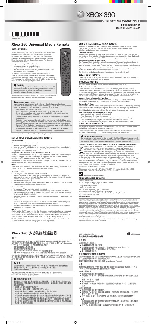
Xbox 360 多功能媒體遙控器只適用於電視和 Xbox 360 主機。
它無法控制 VCR 、DVR 、DVD 播放器或音效設備。
使用多功能媒體遙控器多功能媒體遙控器的運作和任何電視遙控器相同。
它同時可控制 Xbox 360 主機,還提供一個按鍵讓您能立即存取所連接的 Windows Media Center 個人電腦。
控制器的按鍵您的遙控器配有 Xbox 360 按鍵及 A 、B 、X 、Y 按鍵。
您可以使用這些按鍵以及 [OK] 鍵來轉換控制 Xbox 360 主機上的 [Xbox 快顯功能表] 和 [Xbox 設定畫面],就跟其他一般控制器相同。
Windows Media center 開始鍵Windows Media Center 的 [開始] 按鍵可讓您透過 Xbox 360 的主機來存取安裝有 Windows Media Center 的個人電腦。
如果您的設定是在 Xbox 360 主機上使用Windows Media Center ,則按下此按鍵會帶您到 Xbox 設定畫面的 [媒體] 區。
如果尚未設定在您的主機上使用 Windows Media Center ,則按下此按鍵會啟動 [Windows Media Center 安裝精靈]。
如果主機是關閉的,Windows Media Center 開始鍵也能啟動主機。
清理您的遙控器僅可使用乾布或微濕的布清理。
使用清潔劑或試圖清理接頭有可能會損壞您的遙控器。
疑難排解如果您遇到了問題,請嘗試以下所提供的解決方案。
dvd 功能沒有作用有些 DVD 可能不支援所有的 Xbox 360 DVD 播放功能,例如字幕、多國語音、多角度檢視和慢動作播放。
한국어Xbox 360 320GB미디어하드 드라이브Xbox 360® 320GB 미디어 하드 드라이브를 구입해 주셔서 감사합니다. Xbox 320GB 미디어 하드드라이브를 사용하면 게임 또는 음악을 저장하거나 사용자 재생 목록을 만들 수 있고Xbox LIVE®에서 비디오 및 기타 새 콘텐츠를 다운로드하거나 Xbox 1 게임을 즐길 수 있습니다.Xbox 360 320GB 미디어 하드 드라이브는 Xbox 360 비디오 게임 및 엔터테인먼트 시스템에만 사용할 수 있습니다.저장된 게임 및 Xbox LIVE멤버십을 쉽고 편리하게 이동하기 위해 Xbox 360호환 플래시 드라이브또는 휴대용 미디어 플레이어와 같은 기타 USB 대용량 저장 장치를 사용하십시오. 게임이나 기타미디어를 저장할 때, 해당 장치를Xbox 저장 공간으로 설정한 다음 저장할 수 있습니다.참고Xbox 360시스템 소프트웨어가 하드 드라이브의 일부 저장 공간을 사용하므로 사용자가 사용할 수있는 전체 용량은 명시된 것보다 적을 수 있습니다.!경고제품을 사용하기 전에 이 설명서 및Xbox 360 사용 설명서에 명시된 안전을 위한 주의 사항을 읽으십시오. 모든 설명서는 나중에 참고할 수 있도록 보관하십시오. 설명서를 분실한 경우/support를방문하십시오.하드 드라이브 장착 및 분리중요전원이 켜져 있을 때 하드 드라이브를 장착 및 제거하지 마십시오. 또, 하드 드라이브 슬롯 접촉부와 커넥터 접촉부를 손가락이나 금속성 물체로 건드리지 마십시오.하드 드라이브를 장착하려면 다음을 수행하십시오.1 본체를 끕니다.2하드 드라이브 덮개를 밀어 느슨하게 하여 하드 드라이브 덮개를 제거합니다.3하드 드라이브를 바깥쪽 탭과 함께 슬롯 안으로 완전히 밀어 넣습니다.4하드 드라이버 덮개를 덮습니다.하드 드라이브를 분리하려면 다음을 수행하십시오.1본체를 끕니다.2하드 드라이브 덮개를 밀어 느슨하게 하여 하드 드라이브 덮개를 제거합니다.3하드 드라이브 탭을 밀어 본체에서 하드 드라이브를 제거합니다.4하드 드라이버 덮개를 덮습니다.콘텐츠 전송Xbox 360 전송 케이블(별도 구입)을 사용하면 다른Xbox 360 하드 드라이브(모든 용량)에 저장된 모든 콘텐츠를 한 번에 새 하드 드라이브로 옮길 수 있습니다. 하드 드라이브 콘텐츠 전송에 대한 자세한내용은/support를 참고하십시오.하드 드라이브 설정하드 드라이브에 개인의 취향에 따라 이름을 지정할 수 있습니다.하드 드라이브의 이름을 설정하려면 다음을 수행하십시오.1Xbox 360 본체에 하드 드라이브를 장착한 다음 대시보드의 시스템 메모리 영역으로 이동하십시오. 2하드 드라이브를 선택합니다.3장치 옵션에서 하드 드라이브 이름을 설정하십시오.저장된 항목 이동 또는 삭제기존 하드 드라이브의 항목을 플래시 드라이브 또는Xbox와 호환되는속도의1GB이상USB대용량 저장 장치로 이동할 수 있습니다. 장치의호환 여부를 확인하고 Xbox 360 저장 공간과 호환되는 장치를 설정하려면Xbox 360 USB 포트에 장치를 연결한 다음 해당 장치를 대시보드에서 저장공간으로 선택하십시오.또한 항목을 삭제하여 하드 드라이브 저장 공간을 확보할 수 있습니다.하드 드라이브에서 항목을 이동하거나 삭제하려면 다음을 수행하십시오.1Xbox 360본체에 하드 드라이브를 장착한 다음 대시보드의 시스템메모리 영역으로 이동하십시오.2하드 드라이브를 선택합니다.3이동 또는 삭제하려는 항목 종류를 선택합니다.4플래시 드라이브 또는 다른 장치로 이동하려는 항목을 선택하거나, 해당 항목을 하드 드라이브에서 삭제합니다.문제 해결문제가 생긴 경우 아래 제공된 가능한 해결책을 시도해 보십시오.하드 드라이브가 저장 장치로 표시되지 않습니다.하드 드라이브가 저장 장치로 표시되지 않으면 다음을 수행하십시오.1하드 드라이브가 하드 드라이브 슬롯에 완전히 삽입되었는지 확인합니다. 본체를 껐다가 켭니다.2본체를 끄고 하드 드라이브를 제거합니다. 본체를 켰다가 다시 끕니다. 하드 드라이브를 다시 장착합니다.3가능하면 다른 본체에서 하드 드라이브를 테스트하거나 사용 중인 본체에서 다른 하드 드라이브를 테스트하여 문제를 정확히 파악합니다.참고하드 드라이브가 손상되면 Xbox 가이드에 표시되지 않으며 Xbox 360 본체에도 손상을 줄 수있습니다. 하드 드라이브가 충격을 받았거나 액체에 빠졌거나 과도한 열에 노출된 적이 있으면 사용할 수 없을 정도로 손상될 수 있으며 저장 장치 목록에도 표시되지 않습니다.도움이 더 필요한 경우일반적인 질문에 대한 답변, 문제 해결 절차 및 Xbox 고객 지원 센터 연락처 정보를 확인하려면 /support를 방문하십시오.수리 및 서비스를 받기 위해 Xbox 360 본체나 해당 액세서리를 판매점에 직접 가져가지 마십시오.문제 해결 및 서비스 정보를 확인하려면/support를 방문하십시오.!절대 직접 수리하려고 하지 마십시오.Xbox 360본체, 전원 공급 장치 또는 액세서리를 직접 분해, 수리 또는 개조하지 마십시오. 감전이나 화재로 심각한 상해를 입거나 목숨을 잃을 수 있으며 보안상의 이유로 보증도 무효가 됩니다.!질식 위험3세 이하의 유아에게 질식을 일으킬 수 있는 작은 부품이 포함되어 있을 수 있습니다. 작은 부품은 유아의 손이 닿지 않는 곳에 보관하십시오.배터리 및 전기/전자 장비 폐기물(WEEE) 처리제품 또는 제품 패키지에 이 기호가 있으면 해당 제품 또는 포함된 배터리는 가능한 분리수거하거나 재활용될 수 있도록 알맞게 처리하는 것이 바람직합니다. 분리 수거와 재활용은천연자원을 보존하고 인체와 환경에 미칠 수 있는 악영향을 방지하는 데 도움을 줍니다.처리 방식이 올바르지 않으면 전기 및 전자 장비의 유해 물질로 인한 악영향에 피해를입을 수 있습니다.가정 또는 사무실에서만 사용하십시오.기계, 의료, 공업 용도로는 적합하지 않습니다.Microsoft에서 명시적으로 승인하지 않은 변경이나 개조를 할 경우 이 장치의 사용 권한이 취소될 수 있습니다.이 제품은 NRTL 목록(UL, CSA, ETL등)에 등재 및/또는IEC/EN 60950을 준수하는 (CE마크) 정보 기술 장비와함께 사용됩니다.수리 가능한 부품이 포함되어 있지 않습니다.본 장치는 영상 5ºC와 35ºC 사이에서 동작하는 상용 제품입니다.경고이 기기는 가정용(B급)으로 전자파적합등록을 한 기기로서 주로 가정에서 사용하는 것을 목적으로하며, 모든 지역에서 사용할 수 있습니다.저작권URL및 기타인터넷 웹 사이트 참고를 포함한 이 설명서의 내용은 예고 없이 변경될 수 있습니다. 다른 설명이 없는 한, 용례에 사용된 회사, 기관, 제품, 도메인 이름, 전자 메일 주소, 로고, 사람, 장소 및 이벤트 등은 실제데이터가 아닙니다. 어떠한 실제 회사, 기관, 제품, 도메인 이름, 전자 메일 주소, 로고, 사람, 장소 및 이벤트와도 연관시킬 의도가 없으며 그렇게 유추해서도 안 됩니다. 귀하에게 적용되는 모든 저작권법을 준수하는 것은귀하의 책임입니다. 저작권에서의 권리와는 별도로, 이 설명서의 어떠한 부분도Microsoft의 명시적인 서면 승인 없이는 어떠한 형식이나 수단(전자적, 기계적, 복사기에 의한 복사, 디스크 복사 또는 다른 방법) 또는목적으로도 복제되거나, 검색 시스템에 저장 또는 도입되거나, 전송될 수 없습니다.Microsoft는 이 설명서 주요 내용에 관련된 특허권, 특허출원, 상표권, 저작권, 또는 기타 지적 재산권 등을보유할 수 있습니다. 서면으로 체결된 라이선스 계약에 따라 Microsoft로부터 귀하에게 명시적으로 제공된라이선스 이외에, 이 설명서의 제공은 귀하에게 이러한 특허권, 상표권, 저작권, 또는 기타 지적 재산권 등에대한 어떠한 사용권도 허여하지 않습니다.© 2011 Microsoft Corporation. All rights reserved.Microsoft, Xbox, Xbox 360, Xbox LIVE, Xbox로고 및 Xbox LIVE로고는Microsoft그룹 계열사의 상표입니다.移動或刪除已儲存內容您可以將硬碟裡的檔案移動到容量至少有 1GB,且與Xbox 速度相容的快閃磁碟機或 USB 大量儲存裝置中。
DXL360/S/C V2 Digital Protractor User GuideFeatures:1) DXL360S/C: High accuracy ±0.05°, high resolution 0.01°DXL360: ±0.1°, resolution 0.02°, detail check specification2) Dual and Single axis with user friendly LCD display angle3) Rechargeable4) V Shape metal case for easy to fit at the corner or pipe.5) 5 Side Magnetic base6) Audible alarming at settable angle range7) Any angle measurement *DXL360s/c only8) USB / Bluetooth to pc connection need adapter for DXL360 and DXL360s/c. SpecificationsAccuracy:DXL360S/C:0 to 20°: ± (0.05°)20 to 70°: ± (0.1°)70 to 90°: ± (0.05°)DXL360:0 to 20°: ± (0.1°)20 to 70°: ± (0.2°)70 to 90°: ± (0.1°)*After CalibratedMeasuring range:Single axis: 360°, Dual axis: ±40°Resolution:DXL360S/C: 0.01°DXL360: 0.02°Any Angle Measurement 0.5°Accuracy *DXL360s/c:Gyro Rotation Speed *DXL360s/c: <50°/sResponse time: <0.4 secondAudio sound:60dB @ 30cmZero offset drift angle per °C: 0.0058° (typical)Operating temperature: 0 to 50°CStorage temperature: -10 to 60°CUser Interface: Mono-color LCD with backlight Supply Power: Rechargeable Li-Polymer 3.7V Charger port:5V 500mA Mini type-B USB port Power Consumption: Standby: 10uA, Operation: 20mA. Standby Battery Life:4000 hoursOperating Battery Life: 40 hoursDimensions(in mm):70(L) x 70(W) x 23(H)Magnetic Base: affix at 4 cornerMagnetic Force: N48Weight: 120gramButton FunctionsButtonFunction DescriptionsNormal Mode MENU ModePOWER In normal operation, this button turns the deviceON/OFF.Serves as theescape key atmenu modeZERO When pressed, the current reading is set tozero; subsequent measurements are relative tothis reading. The LCD will show the icon toindicate the device is in zero mode.Press and hold for 3 seconds to enable ordisable sound. The icon on LCD will bedisplaced accordingly. The buzzer alarmingcould be set at different accuracy level. Refer tosection “Angle Alarming”.Serves as theupward key foroption selection.HOLD When pressed, the current value will freeze; theunit icon flashes to indicate the readingis on hold.Serves as thedownward key atmenu modeSET Press and hold for 3 seconds to enter MENUmode, for set mode options.Serves as the Setkey.ANGLE *DXL360S/Conly Any angle measurement start button. Refer tosection “Any Angle”Press and hold for 3 seconds to enter MENUmode, for set mode options.Serves as the Setkey.LCD Icons RepresentationsBattery status indication iconsThese icons indicate the battery level. There are 3 levelsrepresenting empty, half and full.In dual-axis mode, the LCD displays the direction of tiltgraphically. It will show as E bubble to display the direction of tiltDegree mode. Flash when unit is in HOLD modemm/M, the height of one end for 1m long plate.Gradient % mode. Flash when unit is in HOLD mode*DXL360S/C OnlySound notification on.Blank as offShow this logo as relative value is showing. When the Zerobutton is pressed, the unit reset current angle to zero.Direction of tilt icons, show the tilt angle directionDual-Axis Mode. Both the X and Y axis angle will be showed.Dual axis mode measures inclination up to +-40 degree for eachaxis before it automatically switch to single axis mode.Single Axis Mode. Measure slope up to +-90 degree.The triangle icon indicates the direction of tilt with respect to thebottom right corner of the unit.Battery ChargingIt has a built in Lithium Ion rechargeable battery. A standard charger is supplied that the input voltage is 110V to 240V AC, 50/60Hz, and the output is 5V DC, 500mA. The charger operating procedure is list below:1) Plug the Charger into AC socket, the RED indicator on the charger should turnedON,2) Plug the USB charging cable to the Charger,3) Insert the other end of the USB cable to the unit,4) The battery icon on the LCD blinks to indicate charging in process. Upon chargingcomplete, the icon stops blinking.5) The charging time is approx. 3 hours.The unit could also be charged by connecting the USB cable to the unit and a computer’s USB port. This has the same effect when charging the unit with the provided adaptor. Note: When the unit is turned OFF, and plug in the USB charge cable, the LCD will no show anything, it is NORMAL. Once the unit is turned ON, the battery icon should flash indicating the unit is in charging mode.Relative/ Absolute MeasurementRelative MeasurementLCD Icon:Absolute MeasurementLCD Icon: BlankRelative and Absolute Mode Switching:1 Pre ss and release the “ZERO” key to set the relative measurement zeropoint2 Press and release the “ZERO” key to cancel the relative zero point andback to absolute measurement mode.Hold FunctionHolding Mode:LCD Icon blinking:Holding function:1. Press and release the “HOLD” key to activate holding function, digit willfreeze.2. Press and release the “HOLD” key to cancel the holding function.Auto Power OffFor no movement in 30 minutes, the unit will power off.Or we can set to never sleep mode at below instruction.Power auto off setting:1. Press and hold “SET” / “ANGLE” key and enter MENU mode2. Select “POWER” by “ZERO” and “HOLD” key, press “SET” key to enter Powermode3. Scroll “NEVER” or “30MIN” by “ON/OFF” and “HOLD” key4. Press “SET” key to confi rm NEVER or 30MIN (30 minutes) sleepRestore Factory SettingWhen you find that the unit is abnormal, you can restore the unit to factory setting.All calibration setting will be restored to factory setting.*Not suggest restore to factory setting in normal status, for accuracy drift, please follow Calibration. After factory set, please redo calibration to ensure the accuracy. Restore to factory setting:1. Press and hold “SET ” / “ANGLE ” key and enter MENU mode2. Select “FACTORY SET” by “ZERO ” and “HOLD” key, press “SET ” key to enter FACTORY SET mode3. Scroll “YES” or “NO” by “ZERO ” and “HOLD” key4. Press “SET ” key to confirmAngle Alarming Alarming Mode: LCD Icon:Alarming Angle setting:1. Press and hold “SET ” / “ANGLE ” key and enter MENU mode2. Select “BUZZER” by “ZERO ” and “HOLD” key,press “SET ” or “ANGLE ” key to enter BUZZER settingPress and hold “ZERO ” and “HOLD” key for fast scrolling the digit. 3. Press “SET ” or “ANGLE ” to enter setting valueBUZZER>SINGLE : 0 0 . 0 0 DUAL. X: 0 0 . 0 0 DUAL. Y: 0 0 . 0 0 RANGE : 0 0 . 5 0 ACTIVE : IN OUTSINGLE Vertical / Single axis mode alarming angle (Degree)DUAL.X Horizontal/ Dual axis mode X axis alarming angle (Degree)DUAL.Y Horizontal/ Dual axis mode Y axis alarming angle (Degree)RANGE The range (Degree)that will trigger the audible alarmingFor example: SINGLE. set to 20.00RANGE set to 01.00While the unit is in +19° to +21°or -19° to -21°, the unit will alarm ACTIVE IN or OUT to set the alarm will alarm in of range or out of rangeCalibrationCalibrate the unit, once you found that there is accuracy drift on the unit. You can verify the accuracy at below step:At Step1, you measured X and Y value, X1 and Y1At Step2, you measured X2 and Y2, in theory X1=-X2, Y1=-Y2.If the error is too large, you can enter calibration mode to eliminate the errorAccuracy drift is causing by large ambient temperature change (5 to 10 Degree Celsius)or the unit has been dropped.Calibration Procedure:Step 1: Press and hold the “SET” or “ANGLE” key enter Menu mode. Select “Calibration” mode, press “SET”. Place the unit on a flat table (no need perfect level table) LCD display “CALIBRATE DUAL AXIS PRESS SET”, press “SET” and buzzer will beep; wait until the beep sound stop. While the buzzer is beeping keep the unit stable.Step 2: Then rotate the unit 180 degree with the other side against the same place.Press the Set button again, and wait for the beep finished.Step 3:LCD display “CALIBRATE HORIZONTAL PRESS SET”. Place the unit horizontal like the picture “STEP 3” and then press “SET”, wait until the beep sound stop.Step 4: Then rotat e the unit 180 degree at the same place. Press the “ZERO” button again, and wait for the beep finished.Step 5:LCD display “CALIBRATE VERTICAL PRESS SET”, mention that the ON/OFF Key at upper side, hold on a flat wall. And then press “SET” Key. Wait for the “Beep” sound stop.Step 6: Then rotate the unit 180 degree with the other side against the same place of wall (ON/OFF Key at upper side). Press the Set button again, and wait for the beep finished. Now, the LCD should go back to the selection menu. The calibration is done, by selecting “Back” to go back for normal operationANY ANGLE measurement: *DXL360S/C onlyAny angle measurement is using gyro technique.You can measure the angle between two faces, not only in earth gravity direction.1) Press Angle key at the first face, and then rotate slowly and must keep the rotationaxis to another testing face2) It will then show the angle once you not move the unit.The rotation axis:Any Angle Measurement Method:Example: Measure angle between two wooden walls is 88.9°Calibrate Gyro *DXL360S1) Place Unit At Flat Table And then Press Set2) Flip 360 degree in clockwise and then press setPlease rotate slowly to increase the accuracy3) Place unit at flat table and then press set4) Flip 360 degree counter clockwise and then press setPlease rotate slowly to increase the accuracyPC CommunicationIt has a PC data logging function.For DXL360SC you can directly plug the USB cable between PC and protractor by miniUSB cableFor DXL360/S You can not directly plug the USB cable between PC to protractor by a general USB cable.You need to optional purchase the PC adapter SVRS232You can continue to data logging X and Y inclination data to PC.Sampling time is around 2 Hz.Specification:1) RS232 Com Port 9600 baud rate2) USB connection ( include a RS232 to USB adapter)3) Format will output ASCII: example for x is 0, Y is -88.88 X+0000Y-8888 Detail can visit our website or contact our sales person.DXL360/S/C V2 数字角度尺使用说明书产品特点:1) DXL360S/C: 高精度±0.05°, 高分辨率0.01°DXL360: 精度±0.1°, 分辨率0.02°, 详情参阅说明书。